EP4481418A1 - Battery management system having hierarchical structure and method for operating same - Google Patents
Battery management system having hierarchical structure and method for operating same Download PDFInfo
- Publication number
- EP4481418A1 EP4481418A1 EP23868322.1A EP23868322A EP4481418A1 EP 4481418 A1 EP4481418 A1 EP 4481418A1 EP 23868322 A EP23868322 A EP 23868322A EP 4481418 A1 EP4481418 A1 EP 4481418A1
- Authority
- EP
- European Patent Office
- Prior art keywords
- battery
- state information
- group
- management system
- batteries
- Prior art date
- Legal status (The legal status is an assumption and is not a legal conclusion. Google has not performed a legal analysis and makes no representation as to the accuracy of the status listed.)
- Pending
Links
Images




Classifications
-
- H—ELECTRICITY
- H01—ELECTRIC ELEMENTS
- H01M—PROCESSES OR MEANS, e.g. BATTERIES, FOR THE DIRECT CONVERSION OF CHEMICAL ENERGY INTO ELECTRICAL ENERGY
- H01M10/00—Secondary cells; Manufacture thereof
- H01M10/42—Methods or arrangements for servicing or maintenance of secondary cells or secondary half-cells
- H01M10/425—Structural combination with electronic components, e.g. electronic circuits integrated to the outside of the casing
-
- H—ELECTRICITY
- H02—GENERATION; CONVERSION OR DISTRIBUTION OF ELECTRIC POWER
- H02J—ELECTRIC POWER NETWORKS; CIRCUIT ARRANGEMENTS OR SYSTEMS FOR SUPPLYING OR DISTRIBUTING ELECTRIC POWER; SYSTEMS FOR STORING ELECTRIC ENERGY
- H02J7/00—Circuit arrangements for charging or discharging batteries or for supplying loads from batteries
- H02J7/80—Circuit arrangements for charging or discharging batteries or for supplying loads from batteries including monitoring or indicating arrangements
-
- G—PHYSICS
- G01—MEASURING; TESTING
- G01R—MEASURING ELECTRIC VARIABLES; MEASURING MAGNETIC VARIABLES
- G01R31/00—Arrangements for testing electric properties; Arrangements for locating electric faults; Arrangements for electrical testing characterised by what is being tested not provided for elsewhere
- G01R31/36—Arrangements for testing, measuring or monitoring the electrical condition of accumulators or electric batteries, e.g. capacity or state of charge [SoC]
- G01R31/382—Arrangements for monitoring battery or accumulator variables, e.g. SoC
-
- H—ELECTRICITY
- H01—ELECTRIC ELEMENTS
- H01M—PROCESSES OR MEANS, e.g. BATTERIES, FOR THE DIRECT CONVERSION OF CHEMICAL ENERGY INTO ELECTRICAL ENERGY
- H01M10/00—Secondary cells; Manufacture thereof
- H01M10/42—Methods or arrangements for servicing or maintenance of secondary cells or secondary half-cells
- H01M10/48—Accumulators combined with arrangements for measuring, testing or indicating the condition of cells, e.g. the level or density of the electrolyte
-
- H—ELECTRICITY
- H02—GENERATION; CONVERSION OR DISTRIBUTION OF ELECTRIC POWER
- H02J—ELECTRIC POWER NETWORKS; CIRCUIT ARRANGEMENTS OR SYSTEMS FOR SUPPLYING OR DISTRIBUTING ELECTRIC POWER; SYSTEMS FOR STORING ELECTRIC ENERGY
- H02J13/00—Circuit arrangements for providing remote monitoring or remote control of equipment in a power distribution network
- H02J13/12—Monitoring network conditions, e.g. electrical magnitudes or operational status
-
- H—ELECTRICITY
- H01—ELECTRIC ELEMENTS
- H01M—PROCESSES OR MEANS, e.g. BATTERIES, FOR THE DIRECT CONVERSION OF CHEMICAL ENERGY INTO ELECTRICAL ENERGY
- H01M10/00—Secondary cells; Manufacture thereof
- H01M10/42—Methods or arrangements for servicing or maintenance of secondary cells or secondary half-cells
- H01M10/425—Structural combination with electronic components, e.g. electronic circuits integrated to the outside of the casing
- H01M2010/4271—Battery management systems including electronic circuits, e.g. control of current or voltage to keep battery in healthy state, cell balancing
-
- H—ELECTRICITY
- H01—ELECTRIC ELEMENTS
- H01M—PROCESSES OR MEANS, e.g. BATTERIES, FOR THE DIRECT CONVERSION OF CHEMICAL ENERGY INTO ELECTRICAL ENERGY
- H01M10/00—Secondary cells; Manufacture thereof
- H01M10/42—Methods or arrangements for servicing or maintenance of secondary cells or secondary half-cells
- H01M10/425—Structural combination with electronic components, e.g. electronic circuits integrated to the outside of the casing
- H01M2010/4278—Systems for data transfer from batteries, e.g. transfer of battery parameters to a controller, data transferred between battery controller and main controller
-
- H—ELECTRICITY
- H02—GENERATION; CONVERSION OR DISTRIBUTION OF ELECTRIC POWER
- H02J—ELECTRIC POWER NETWORKS; CIRCUIT ARRANGEMENTS OR SYSTEMS FOR SUPPLYING OR DISTRIBUTING ELECTRIC POWER; SYSTEMS FOR STORING ELECTRIC ENERGY
- H02J13/00—Circuit arrangements for providing remote monitoring or remote control of equipment in a power distribution network
- H02J13/13—Circuit arrangements for providing remote monitoring or remote control of equipment in a power distribution network characterised by the transmission of data to equipment in the power network
- H02J13/1321—Circuit arrangements for providing remote monitoring or remote control of equipment in a power distribution network characterised by the transmission of data to equipment in the power network using a wired telecommunication network or a data transmission bus
-
- Y—GENERAL TAGGING OF NEW TECHNOLOGICAL DEVELOPMENTS; GENERAL TAGGING OF CROSS-SECTIONAL TECHNOLOGIES SPANNING OVER SEVERAL SECTIONS OF THE IPC; TECHNICAL SUBJECTS COVERED BY FORMER USPC CROSS-REFERENCE ART COLLECTIONS [XRACs] AND DIGESTS
- Y02—TECHNOLOGIES OR APPLICATIONS FOR MITIGATION OR ADAPTATION AGAINST CLIMATE CHANGE
- Y02E—REDUCTION OF GREENHOUSE GAS [GHG] EMISSIONS, RELATED TO ENERGY GENERATION, TRANSMISSION OR DISTRIBUTION
- Y02E60/00—Enabling technologies; Technologies with a potential or indirect contribution to GHG emissions mitigation
- Y02E60/10—Energy storage using batteries
Definitions
- the present invention relates to a battery management system having a hierarchical structure and an operating method thereof, and more particularly, to a battery management system including a master BMS and a slave BMS and an operating method thereof.
- a secondary battery is a battery that can be recharged and reused even after being discharged.
- the secondary battery can be used as an energy source for small devices such as mobile phones, tablet PCs and vacuum cleaners, and also used as an energy source for medium and large devices such as ESS (Energy Storage System) for automobiles and smart grids.
- ESS Electronicgy Storage System
- the secondary battery is applied to a system in a form of an assembly such as a battery module in which a plurality of battery cells are connected in series and parallel or a battery pack in which battery modules are connected in series and parallel according to system requirements.
- a high-capacity battery system in which a plurality of battery packs are connected in parallel may be applied in order to satisfy a required capacity of the device.
- a battery management system that monitors and controls a state and operations of a battery pack may have a hierarchical structure in order to efficiently monitor and control all battery cells included in the battery pack. More specifically, the battery management system may include a plurality of slave BMSs that collect state information of battery cells or battery modules and a master BMS that collects state information of a battery pack, and receives cell/module state information from the slave BMSs for integrated monitoring and control.
- the hierarchical structured battery management system In order for the hierarchical structured battery management system to perform state diagnosis more accurately, it is necessary to diagnose whether or not the battery is abnormal using several pieces of state information measured at the same time, but a device that collect pack state information and a device that collect information about cell or module state are configured separately and communication lines of respective devices are separated, so that a time error among several pieces of state information may occur. Due to this time error among the several pieces of state information, the reliability for diagnosis result of the battery management system may be limited.
- embodiments of the present disclosure provide a battery system having a hierarchical structure.
- embodiments of the present disclosure also provide a method for operating a battery system having a hierarchical structure.
- a battery management system (BMS) having a hierarchical structure may include a plurality of slave BMSs and a master BMS configured to interwork with the plurality of slave BMSs and to monitor a battery group including a plurality of batteries.
- the master BMS may be configured to collect state information on one or more batteries from the plurality of slave BMSs and to collect state information on the battery group from a group state information collecting device provided in the master BMS and the plurality of slave BMSs and the group state information collecting device may be configured to be sequentially connected through a serial communication network.
- the master BMS may include: a controller; and a communication interface device.
- the controller and the communication interface device may be configured to be sequentially connected to the plurality of slave BMSs and the group state information collecting device through the serial communication network.
- the controller may be configured to receive the status information on the one or more batteries and the status information on the battery group through the communication interface device, wherein the status information on the one or more batteries and the status information on the battery group are generated at the same time.
- the controller may be configured to diagnose whether the battery or the battery group is abnormal based on the received state information on the one or more batteries and the state information on the battery group.
- the communication interface device may be directly connected to the slave BMS located at an end of the plurality of slave BMSs through a serial communication line.
- the group state information collecting device may be configured to be switched to an inactive state and the plurality of slave BMSs are configured to wake-up at a predefined time.
- the plurality of slave BMSs may wake-up every predefined unit time to collect state information on the one or more batteries, in an OFF state of the battery management system and diagnose whether a battery to be managed is abnormal based on the collected state information.
- the slave BMS may transmit an abnormality signal to the communication interface device through the serial communication line and the communication interface device may be configured to transmit a wake-up signal to the controller to switch the battery management system to an ON state.
- the state information on the battery group may include one or more information of a voltage value, a current value, and an insulation resistance value in units of battery groups, and the state information on the one or more batteries may include one or more information of voltage values, current values, and temperature values in units of battery cells or battery subgroups.
- the group state information collecting device may be configured as an integrated module including a group voltage information collecting module, a group current information collecting module and an insulation resistance information collecting module.
- an operating method of a battery management system which includes a plurality of slave BMSs and a master BMS sequentially connected with the plurality of slave BMSs through a serial communication network, may include: collecting, by the plurality of slave BMSs, state information on one or more batteries; collecting, by a group state information collecting device provided in the master BMS, state information on the battery group; receiving, by a controller of the master BMS, status information on the one or more batteries and status information on the battery group through a communication interface device of the master BMS; and monitoring abnormality in the one or more batteries or in the battery group based on the collected state information.
- BMS battery management system
- the controller and the communication interface device may be sequentially connected to the plurality of slave BMSs and the group state information collecting device through the serial communication network.
- the receiving status information may include receiving, through the communication interface device, status information on the one or more batteries and status information on the battery group which are generated at the same time.
- the monitoring abnormality may include diagnosing whether the battery or the battery group is abnormal based on the received state information on the one or more batteries and the state information on the battery group.
- the communication interface device may directly be connected to the slave BMS located at an end of the plurality of slave BMSs through a serial communication line.
- the operating method of a battery management system may further include: upon the battery management system being switched to OFF state, collecting, by the plurality of slave BMSs, state information on the at least one battery by activating the plurality of slave BMSs at predetermined unit time intervals; and diagnosing, by the plurality of slave BMSs, whether or not a battery managed is abnormal based on the collected state information.
- the operating method of a battery management system may further include: upon an abnormality occurring in one or more batteries, transmitting, by the slave BMS, an abnormality signal to the communication interface device through the serial communication line; and transmitting, by the communication interface device, a wake-up signal to the controller to switch the battery management system to an ON state.
- the state information on the battery group may include one or more information of a voltage value, a current value, and an insulation resistance value in units of battery groups, and the state information on the one or more batteries may include one or more information of voltage values, current values, and temperature values in units of battery cells or battery subgroups.
- the battery management system can diagnose a battery system based on time-synchronized state information, thereby improving reliability of monitoring and diagnosis results by the battery management system.
- monitoring and diagnosis can be stably performed even in an OFF state of the battery management system according to embodiments of the present invention.
- first, second, A, B, and the like may be used herein to describe various elements, these elements should not be limited by these terms. These terms are only used to distinguish one element from another. For example, a first element could be termed a second element, and, similarly, a second element could be termed a first element, without departing from the scope of the present invention.
- the term "and/or" includes combinations of a plurality of associated listed items or any of the plurality of associated listed items.
- FIG. 1 is a block diagram of a general battery management system.
- the battery management system may include a master BMS 10 and a plurality of slave BMSs 20.
- the master BMS 10 is an upper layer BMS that monitors and controls a battery system including a plurality of battery modules #1 to #N.
- the master BMS 10 may include a plurality of pack state information collecting devices that collect state information of the battery pack. As shown in FIG. 1 , the state information collecting device may include a pack voltage information collecting module, a pack current information collecting module, and an insulation resistance information collecting module.
- the plurality of slave BMSs 20 each of which is a lower layer BMS are provided in correspondence with the plurality of battery modules #1 to #N, collect state information on the corresponding battery modules, and transmit the collected state information to the master BMS 10.
- each of the slave BMSs may include a device for collecting module state information including one or more information of a voltage value, a current value, and a temperature value of each cell included in the battery module, and a voltage value, a current value, and a temperature value of each battery module, or each of the slave BMSs may be connected to the device for collecting module state information.
- the master BMS 10 may include a communication interface device, and may be configured to transmit/receive data with a plurality of slave BMSs 20 through the communication interface device.
- the master BMS 10 may receive module state information (cell state information and module state information) from each of the plurality of slave BMSs 20 through the communication interface device.
- the master BMS 10 may be configured to include a controller that receives pack state information from pack state information collecting devices (pack voltage information collecting module, pack current information collecting module, and insulation resistance information collecting module) provided therein, and receives module state information from each of the plurality of slave BMSs 20 through the communication interface.
- the controller of the master BMS 10 may monitor the collected pack state information and module state information and diagnose whether the battery system is abnormal.
- pack state information collecting devices and module state information collection devices are separately configured, and communication is performed while a communication line for collecting pack state information and a communication line for collecting module state information are separated. Accordingly, several pieces of state information collected by the controller are data with a time error that is not measured at the same time. Due to this time error among several pieces of state information, the reliability for diagnosis result of the battery management system may be limited.
- the present invention is presented to solve these technical problems.
- the structure and operation method of a battery management system according to various embodiments of the present disclosure will be described in detail with reference to FIGS. 2 to 6 .
- FIG. 2 is a block diagram of a battery management system according to embodiments of the present invention.
- a battery management system may include a master BMS 100 and a plurality of slave BMS 200.
- the master BMS 100 is an upper layer BMS that monitors and controls a battery system including a plurality of batteries.
- the master BMS 100 may include a controller 110, a communication interface device 120 and a group state information collecting device 130.
- the controller 110 may monitor states of one or more of the batteries and battery groups included in the battery system and diagnose abnormalities.
- the battery group may mean a battery module, a battery pack, a battery rack, or a battery bank.
- the controller 110 may diagnose whether or not there is an abnormality in one or more of the batteries and battery groups based on the state information on the battery group transmitted from the group state information collecting device and the state information on one or more batteries transmitted from the plurality of slave BMSs 200.
- the communication interface device 120 may include a communication module that receives state information from the group state information collecting device 130 and the plurality of slave BMSs 200 and transmits the state information to the controller 110.
- the group state information collecting device 130 may collect state information in units of battery groups and transmit the collected group state information to the communication interface device 120.
- the group state information collecting device 130 may be configured as an integrated module including a group voltage information collecting module, a group current information collecting module, and an insulation resistance information collecting module.
- the group state information collecting device 130 may be configured as one integrated module including a group voltage information collecting module, a group current information collecting module, and an insulation resistance information collecting module, and configured to simultaneously transmit the collected group state information (e.g., voltage value, current value, and insulation resistance value of each battery pack unit) to the communication interface device 120.
- the plurality of slave BMSs 200 are lower layer BMSs that manage one or more batteries, respectively.
- each of the slave BMSs may collect state information on a corresponding battery to be managed and transmit collected battery state information to the master BMS 100.
- Each of the slave BMSs may be configured to include a state information collecting device for collecting state information of a battery to be managed, or to be connected to the state information collecting device.
- the battery state information collected by a slave BMS may include state information of one or more of a voltage value, a current value, and a temperature value of a battery cell or battery subgroup unit (e.g., module unit).
- the plurality of slave BMSs 200 may be sequentially connected to the group state information collecting device 130 of the master BMS 100 through a serial communication network.
- the controller 110 and the communication interface device 120 of the master BMS 100 may be sequentially connected to the group state information collecting device 130 and the plurality of slave BMSs 200 through a serial communication network.
- a controller 110, a communication interface device 120, a group state information collecting device 130, and a plurality of slave BMSs 200 may be sequentially connected through a serial communication network 300.
- Each of the components 110, 120, and 130 of the master BMS 100 and each of the plurality of slave BMSs 200 may include a communication module for forming the serial connection network 300 shown in FIG. 2 .
- the serial connection network 300 may correspond to a daisy-chain communication network, and each of the components 110, 120, 130, and 200 in the master BMS 100 may include a data transceiving module to form a daisy-chain communication network.
- each collected battery state information may be transmitted to the controller 110 through the serial communication network 300.
- the group state information collecting device 130 may transmit the collected group state information to the controller 110 through the serial communication network 300.
- the group state information collecting device 130 as described above, may be configured as an integrated module including a group voltage information collecting module, a group current information collecting module, and an insulation resistance information collecting module, and thus, group state information including voltage values, current values, and insulation resistance values in group units may be transmitted to the controller 110.
- the battery state information and the group state information may correspond to state information generated at the same time.
- the controller 110 may receive pieces of time-synchronized state information (e.g., battery cell state information, module state information, and pack state information), monitor the battery system using the received state information, and diagnose abnormalities in the battery system. Accordingly, reliability of monitoring and diagnosis results by the battery management system may be improved.
- time-synchronized state information e.g., battery cell state information, module state information, and pack state information
- FIG. 3 is a block diagram illustrating an implementation example of a battery management system according to the present invention.
- FIG. 3 is an implementation example of a battery management system in which a master BMS corresponds to a pack BMS and a slave BMS corresponds to a module BMS.
- the battery management system shown in FIG. 3 is an example for clear description of the present invention, and the scope of the present invention is not limited thereto.
- a battery management system may include a master BMS 100' and a plurality of slave BMSs 200'.
- the master BMS 100' may correspond to a pack BMS that monitors and controls a battery pack including a plurality of battery modules.
- the master BMS 100' may include a controller 110', a communication interface device 120', and a pack state information collecting device 130'.
- the controller 110' may monitor the state of the battery pack and diagnose abnormalities in the battery pack.
- the controller 110' may diagnose whether one or more of the battery cell, the battery module, and the battery pack are abnormal based on one or more of the pack state information transmitted from the pack state information collecting device and the module state information transmitted from the plurality of slave BMSs 200'.
- the communication interface device 120' may be configured to include a communication module that receives state information from the plurality of slave BMSs 200' and a pack state information collecting device 130', and transmits the received state information to the controller 110'.
- the pack state information collecting device 130' may collect pack state information in units of battery packs and transmit the collected pack state information to the communication interface device 120'.
- the pack state information collecting device 130' may be configured as an integrated module including a pack voltage information collecting module, a pack current information collecting module, and an insulation resistance information collecting module.
- the plurality of slave BMSs 200' may correspond to module BMSs provided in correspondence with the plurality of battery modules #1 to #N, respectively.
- the slave BMS may collect state information on the corresponding battery module and transmit the collected module state information to the master BMS 100'.
- Each of the slave BMSs may include a module state information collecting device for collecting module status information, or may be configured to be connected to the module state information collection device.
- the module state information may include one or more state information of a voltage value, a current value, and a temperature value of each cell included in the battery module, and a voltage value, a current value, and a temperature value of each battery module.
- the plurality of slave BMSs 200' may be sequentially connected to the pack state information collecting device 130' of the master BMS 100' through a serial communication network.
- the controller 110' and the communication interface device 120' of the master BMS 100' may be sequentially connected to the pack state information collecting device 130' and the plurality of slave BMSs 200' through a serial communication network.
- Each of the components 110', 120', and 130' of the master BMS 100' and each of the plurality of slave BMSs 200' may include a communication module to form the serial connection network 300' shown in FIG. 3 .
- each collected module state information may be transmitted to the controller 110' through the serial communication network 300'.
- the pack state information collecting device 130' may transmit the collected pack state information to the controller 110' through the serial communication network 300'.
- the module state information and the pack state information may correspond to state information generated at the same time.
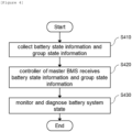
- FIG. 4 is an operation flowchart of a method for operating a battery management system according to embodiments of the present invention.
- the plurality of slave BMSs may collect state information on one or more batteries and the group state information collecting device of the master BMS may collect state information on battery groups (S410).
- the state information on the battery group may include information on one or more of a voltage value, a current value, and an insulation resistance value in units of battery group (e.g., in units of pack).
- the state information on one or more batteries may include one or more of a voltage value, a current value, and a temperature value in units of battery cells or battery subgroups (e.g., in units of module).
- the collected battery state information and group state information may correspond to time-synchronized state information generated at the same time.
- the controller of the master BMS may receive battery state information and group state information (S420). More specifically, the plurality of slave BMSs and the group state information collecting device may transmit battery state information and group state information to the communication interface device through a serial communication network, and the communication interface device may transfer the delivered battery state information and group status information to the controller.
- the controller may monitor and diagnose a battery or a battery group based on the received battery state information and group state information (S430).
- FIG. 5 is a block diagram of a battery management system to which a serial communication line according to embodiments of the present invention is applied.
- the battery management system in FIG. 5 shows a structure further including a serial communication line 400 in the battery management system shown in FIG. 2 , the serial communication line 400 directly connecting the slave BMS located at the end and the communication interface device 120.
- the slave BMS (#N) positioned at the end, among the plurality of slave BMSs 200, may be configured to be directly connected to the communication interface device 120 through the serial communication line 400.
- the battery management system may monitor the battery system even when it is in an OFF state, and may be switched to an ON state when abnormality occurs in the battery system.
- the group state information collecting device 130 may be configured to be switched to an inactive state, and the plurality of slave BMSs 200 to wake-up at a predefined time.
- the group state information collecting device 130 may be configured not to collect group state information, and the plurality of slave BMSs 200 may be configured to receive power through a regular power supply, wake-up every pre-defined time, and collect battery state information (e.g., voltage value, current value, temperature value of a cell, voltage value, current value, temperature value, of a module, etc.).
- battery state information e.g., voltage value, current value, temperature value of a cell, voltage value, current value, temperature value, of a module, etc.
- the plurality of slave BMSs 200 may diagnose whether a battery under management is abnormal based on the collected battery state information.
- one or more corresponding slave BMSs may generate an abnormality signal.
- the corresponding slave BMS may transfer the generated abnormality signal to the communication interface device 120 through the serial communication line 400.
- the plurality of slave BMSs 200 may monitor respective batteries being managed, and, when an abnormality occurs, the slave BMS managing the abnormal battery may transmit an abnormality signal to the communication interface device 120 through the serial communication line 400 (a direction opposite to the communication direction in ON state shown in FIG. 2 ).
- the communication interface device 120 may be configured to operate by receiving power through a constant power supply in an OFF state of the battery management system.
- the communication interface device 120 may be configured to switch the battery management system into an ON state when an abnormality occurs in one or more batteries.
- the plurality of slave BMSs 200 diagnose whether a battery under management is abnormal, and may transmit an abnormality signal indicating an abnormality to the communication interface device 120 through the serial communication line 400 when an abnormality occurs.
- the communication interface device 120 may generate a wake-up signal using a wake-up circuit and transmit the wake-up signal to the controller 110.
- the controller 110 may receive the wake-up signal and turn the battery management system to ON state.
- the battery system in OFF state of the battery management system, the battery system may be monitored through the communication interface device 120, the slave BMS 200, and a separate serial communication line 400, whereas, when an abnormality occurs, the battery management system is switched to ON state and the controller 110 may diagnose abnormality in the entire battery system.
- FIG. 6 is an operation flowchart of a method of operating the battery management system shown in FIG. 5 .
- the group state information collecting device may be turned into an inactive state (S610).
- the plurality of slave BMSs may be supplied with power through a constant power supply, wake-up every predefined time, and collect battery state information (e.g., a voltage value, a current value, and a temperature value of a cell, and a voltage value, a current value, and a temperature value of a module, etc.)(S620).
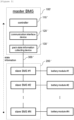
- battery state information e.g., a voltage value, a current value, and a temperature value of a cell, and a voltage value, a current value, and a temperature value of a module, etc.
- Each of the slave BMSs may diagnose whether or not the battery under management is abnormal based on the battery state information (S630).
- the communication interface device may switch the battery management system to an ON state (S640). For example, when an abnormality occurs in a specific battery module, the communication interface device may receive an abnormality signal from a slave BMS corresponding to the module generating abnormality. Thereafter, the communication interface device may generate a wake-up signal through a wake-up circuit and transmit the wake-up signal to the controller, and the controller may turn the battery management system into an ON state.
- the operations of the method according to the embodiments of the present invention may be implemented as a computer-readable program or code on a computer-readable recording medium.
- the computer-readable recording medium includes all types of recording devices in which data readable by a computer system is stored.
- the computer-readable recording medium may be distributed in a network-connected computer system to store and execute computer-readable programs or codes in a distributed manner.
- a block or apparatus corresponds to a method step or feature of a method step.
- aspects described in the context of a method may also represent a feature of a corresponding block or item or a corresponding apparatus.
- Some or all of the method steps may be performed by (or using) a hardware device, such as, for example, a microprocessor, a programmable computer, or an electronic circuit. In some embodiments, one or more of the most important method steps may be performed by such an apparatus.
Landscapes
- Engineering & Computer Science (AREA)
- General Chemical & Material Sciences (AREA)
- Manufacturing & Machinery (AREA)
- Chemical & Material Sciences (AREA)
- Chemical Kinetics & Catalysis (AREA)
- Electrochemistry (AREA)
- Microelectronics & Electronic Packaging (AREA)
- Power Engineering (AREA)
- Physics & Mathematics (AREA)
- General Physics & Mathematics (AREA)
- Secondary Cells (AREA)
- Charge And Discharge Circuits For Batteries Or The Like (AREA)
- Tests Of Electric Status Of Batteries (AREA)
Abstract
Description
- This application claims priority to and the benefit of
Korean Patent Application No.10-2022-0118506 filed in the Korean Intellectual Property Office on September 20, 2022 Korean Patent Application No.10-2023-0074116 filed in the Korean Intellectual Property Office on June 9, 2023 - The present invention relates to a battery management system having a hierarchical structure and an operating method thereof, and more particularly, to a battery management system including a master BMS and a slave BMS and an operating method thereof.
- A secondary battery is a battery that can be recharged and reused even after being discharged. The secondary battery can be used as an energy source for small devices such as mobile phones, tablet PCs and vacuum cleaners, and also used as an energy source for medium and large devices such as ESS (Energy Storage System) for automobiles and smart grids.
- The secondary battery is applied to a system in a form of an assembly such as a battery module in which a plurality of battery cells are connected in series and parallel or a battery pack in which battery modules are connected in series and parallel according to system requirements. In a case of medium or large-sized devices such as electric vehicles, a high-capacity battery system in which a plurality of battery packs are connected in parallel may be applied in order to satisfy a required capacity of the device.
- A battery management system that monitors and controls a state and operations of a battery pack may have a hierarchical structure in order to efficiently monitor and control all battery cells included in the battery pack. More specifically, the battery management system may include a plurality of slave BMSs that collect state information of battery cells or battery modules and a master BMS that collects state information of a battery pack, and receives cell/module state information from the slave BMSs for integrated monitoring and control.
- In order for the hierarchical structured battery management system to perform state diagnosis more accurately, it is necessary to diagnose whether or not the battery is abnormal using several pieces of state information measured at the same time, but a device that collect pack state information and a device that collect information about cell or module state are configured separately and communication lines of respective devices are separated, so that a time error among several pieces of state information may occur. Due to this time error among the several pieces of state information, the reliability for diagnosis result of the battery management system may be limited.
- To obviate one or more problems of the related art, embodiments of the present disclosure provide a battery system having a hierarchical structure.
- To obviate one or more problems of the related art, embodiments of the present disclosure also provide a method for operating a battery system having a hierarchical structure.
- In order to achieve the objective of the present disclosure, a battery management system (BMS) having a hierarchical structure may include a plurality of slave BMSs and a master BMS configured to interwork with the plurality of slave BMSs and to monitor a battery group including a plurality of batteries.
- Here, the master BMS may be configured to collect state information on one or more batteries from the plurality of slave BMSs and to collect state information on the battery group from a group state information collecting device provided in the master BMS and the plurality of slave BMSs and the group state information collecting device may be configured to be sequentially connected through a serial communication network.
- The master BMS may include: a controller; and a communication interface device. Here, the controller and the communication interface device may be configured to be sequentially connected to the plurality of slave BMSs and the group state information collecting device through the serial communication network.
- The controller may be configured to receive the status information on the one or more batteries and the status information on the battery group through the communication interface device, wherein the status information on the one or more batteries and the status information on the battery group are generated at the same time.
- The controller may be configured to diagnose whether the battery or the battery group is abnormal based on the received state information on the one or more batteries and the state information on the battery group.
- The communication interface device may be directly connected to the slave BMS located at an end of the plurality of slave BMSs through a serial communication line.
- Upon the battery management system being switched to OFF state, the group state information collecting device may be configured to be switched to an inactive state and the plurality of slave BMSs are configured to wake-up at a predefined time.
- The plurality of slave BMSs may wake-up every predefined unit time to collect state information on the one or more batteries, in an OFF state of the battery management system and diagnose whether a battery to be managed is abnormal based on the collected state information.
- Upon an abnormality occurring in one or more batteries, the slave BMS may transmit an abnormality signal to the communication interface device through the serial communication line and the communication interface device may be configured to transmit a wake-up signal to the controller to switch the battery management system to an ON state.
- The state information on the battery group may include one or more information of a voltage value, a current value, and an insulation resistance value in units of battery groups, and the state information on the one or more batteries may include one or more information of voltage values, current values, and temperature values in units of battery cells or battery subgroups.
- The group state information collecting device may be configured as an integrated module including a group voltage information collecting module, a group current information collecting module and an insulation resistance information collecting module.
- According to another embodiment of the present disclosure, an operating method of a battery management system (BMS), which includes a plurality of slave BMSs and a master BMS sequentially connected with the plurality of slave BMSs through a serial communication network, may include: collecting, by the plurality of slave BMSs, state information on one or more batteries; collecting, by a group state information collecting device provided in the master BMS, state information on the battery group; receiving, by a controller of the master BMS, status information on the one or more batteries and status information on the battery group through a communication interface device of the master BMS; and monitoring abnormality in the one or more batteries or in the battery group based on the collected state information.
- The controller and the communication interface device may be sequentially connected to the plurality of slave BMSs and the group state information collecting device through the serial communication network.
- The receiving status information may include receiving, through the communication interface device, status information on the one or more batteries and status information on the battery group which are generated at the same time.
- The monitoring abnormality may include diagnosing whether the battery or the battery group is abnormal based on the received state information on the one or more batteries and the state information on the battery group.
- The communication interface device may directly be connected to the slave BMS located at an end of the plurality of slave BMSs through a serial communication line.
- The operating method of a battery management system may further include: upon the battery management system being switched to OFF state, collecting, by the plurality of slave BMSs, state information on the at least one battery by activating the plurality of slave BMSs at predetermined unit time intervals; and diagnosing, by the plurality of slave BMSs, whether or not a battery managed is abnormal based on the collected state information.
- The operating method of a battery management system may further include: upon an abnormality occurring in one or more batteries, transmitting, by the slave BMS, an abnormality signal to the communication interface device through the serial communication line; and transmitting, by the communication interface device, a wake-up signal to the controller to switch the battery management system to an ON state.
- The state information on the battery group may include one or more information of a voltage value, a current value, and an insulation resistance value in units of battery groups, and the state information on the one or more batteries may include one or more information of voltage values, current values, and temperature values in units of battery cells or battery subgroups.
- According to the embodiment of the present invention as described above, the battery management system can diagnose a battery system based on time-synchronized state information, thereby improving reliability of monitoring and diagnosis results by the battery management system.
- In addition, monitoring and diagnosis can be stably performed even in an OFF state of the battery management system according to embodiments of the present invention.
-
-
FIG. 1 is a block diagram of a general battery management system. -
FIG. 2 is a block diagram of a battery management system according to embodiments of the present invention. -
FIG. 3 is a block diagram illustrating an implementation example of a battery management system according to the present invention. -
FIG. 4 is an operation flowchart of a method for operating a battery management system according to embodiments of the present invention. -
FIG. 5 is a block diagram of a battery management system to which a serial communication line according to embodiments of the present invention is applied. -
FIG. 6 is an operation flowchart of a method of operating the battery management system shown inFIG. 5 . - 100:
- Master BMS
- 110:
- controller
- 120:
- communication interface device
- 130:
- group state information collecting device
- 200:
- slave BMS
- 300:
- serial communication network
- 400:
- serial communication line
- The present invention may be modified in various forms and have various embodiments, and specific embodiments thereof are shown by way of example in the drawings and will be described in detail below. It should be understood, however, that there is no intent to limit the present invention to the specific embodiments, but on the contrary, the present invention is to cover all modifications, equivalents, and alternatives falling within the spirit and technical scope of the present invention. Like reference numerals refer to like elements throughout the description of the figures.
- It will be understood that, although the terms such as first, second, A, B, and the like may be used herein to describe various elements, these elements should not be limited by these terms. These terms are only used to distinguish one element from another. For example, a first element could be termed a second element, and, similarly, a second element could be termed a first element, without departing from the scope of the present invention. As used herein, the term "and/or" includes combinations of a plurality of associated listed items or any of the plurality of associated listed items.
- It will be understood that when an element is referred to as being "coupled" or "connected" to another element, it can be directly coupled or connected to the other element or an intervening element may be present. In contrast, when an element is referred to as being "directly coupled" or "directly connected" to another element, there is no intervening element present.
- The terms used herein is for the purpose of describing specific embodiments only and are not intended to limit the present invention. As used herein, the singular forms "a", "an" and "the" are intended to include the plural forms as well, unless the context clearly indicates otherwise. It will be further understood that the terms "comprises", "comprising", "includes", "including" and/or "having", when used herein, specify the presence of stated features, integers, steps, operations, constitutional elements, components and/or combinations thereof, but do not preclude the presence or addition of one or more other features, integers, steps, operations, constitutional elements, components, and/or combinations thereof.
- Unless otherwise defined, all terms used herein, including technical and scientific terms, have the same meanings as commonly understood by one skilled in the art to which the present invention belongs. It will be further understood that terms, such as those defined in commonly used dictionaries, should be interpreted as having meanings that are consistent with their meanings in the context of the relevant art and will not be interpreted in an idealized or overly formal sense unless expressly so defined herein.
-
FIG. 1 is a block diagram of a general battery management system. - Referring to
FIG. 1 , the battery management system may include amaster BMS 10 and a plurality ofslave BMSs 20. - The
master BMS 10 is an upper layer BMS that monitors and controls a battery system including a plurality ofbattery modules # 1 to #N. Themaster BMS 10 may include a plurality of pack state information collecting devices that collect state information of the battery pack. As shown inFIG. 1 , the state information collecting device may include a pack voltage information collecting module, a pack current information collecting module, and an insulation resistance information collecting module. - The plurality of
slave BMSs 20 each of which is a lower layer BMS are provided in correspondence with the plurality ofbattery modules # 1 to #N, collect state information on the corresponding battery modules, and transmit the collected state information to themaster BMS 10. Here, each of the slave BMSs may include a device for collecting module state information including one or more information of a voltage value, a current value, and a temperature value of each cell included in the battery module, and a voltage value, a current value, and a temperature value of each battery module, or each of the slave BMSs may be connected to the device for collecting module state information. - The
master BMS 10 may include a communication interface device, and may be configured to transmit/receive data with a plurality ofslave BMSs 20 through the communication interface device. Here, themaster BMS 10 may receive module state information (cell state information and module state information) from each of the plurality ofslave BMSs 20 through the communication interface device. - Referring to
FIG. 1 , themaster BMS 10 may be configured to include a controller that receives pack state information from pack state information collecting devices (pack voltage information collecting module, pack current information collecting module, and insulation resistance information collecting module) provided therein, and receives module state information from each of the plurality ofslave BMSs 20 through the communication interface. Here, the controller of themaster BMS 10 may monitor the collected pack state information and module state information and diagnose whether the battery system is abnormal. - Referring to
FIG. 1 , in the case of a general battery management system, pack state information collecting devices and module state information collection devices are separately configured, and communication is performed while a communication line for collecting pack state information and a communication line for collecting module state information are separated. Accordingly, several pieces of state information collected by the controller are data with a time error that is not measured at the same time. Due to this time error among several pieces of state information, the reliability for diagnosis result of the battery management system may be limited. - The present invention is presented to solve these technical problems. Hereinafter, the structure and operation method of a battery management system according to various embodiments of the present disclosure will be described in detail with reference to
FIGS. 2 to 6 . -
FIG. 2 is a block diagram of a battery management system according to embodiments of the present invention. - Referring to
FIG. 2 , a battery management system according to embodiments of the present invention may include amaster BMS 100 and a plurality ofslave BMS 200. - The
master BMS 100 is an upper layer BMS that monitors and controls a battery system including a plurality of batteries. - The
master BMS 100 may include acontroller 110, acommunication interface device 120 and a group stateinformation collecting device 130. - The
controller 110 may monitor states of one or more of the batteries and battery groups included in the battery system and diagnose abnormalities. Here, the battery group may mean a battery module, a battery pack, a battery rack, or a battery bank. - The
controller 110 may diagnose whether or not there is an abnormality in one or more of the batteries and battery groups based on the state information on the battery group transmitted from the group state information collecting device and the state information on one or more batteries transmitted from the plurality ofslave BMSs 200. - The
communication interface device 120 may include a communication module that receives state information from the group stateinformation collecting device 130 and the plurality ofslave BMSs 200 and transmits the state information to thecontroller 110. - The group state
information collecting device 130 may collect state information in units of battery groups and transmit the collected group state information to thecommunication interface device 120. Here, the group stateinformation collecting device 130 may be configured as an integrated module including a group voltage information collecting module, a group current information collecting module, and an insulation resistance information collecting module. Other words, unlike a general battery management system as shown inFIG. 1 , the group stateinformation collecting device 130 according to embodiments of the present invention may be configured as one integrated module including a group voltage information collecting module, a group current information collecting module, and an insulation resistance information collecting module, and configured to simultaneously transmit the collected group state information (e.g., voltage value, current value, and insulation resistance value of each battery pack unit) to thecommunication interface device 120. - The plurality of
slave BMSs 200 are lower layer BMSs that manage one or more batteries, respectively. Here, each of the slave BMSs may collect state information on a corresponding battery to be managed and transmit collected battery state information to themaster BMS 100. - Each of the slave BMSs may be configured to include a state information collecting device for collecting state information of a battery to be managed, or to be connected to the state information collecting device. Here, the battery state information collected by a slave BMS may include state information of one or more of a voltage value, a current value, and a temperature value of a battery cell or battery subgroup unit (e.g., module unit).
- The plurality of
slave BMSs 200 may be sequentially connected to the group stateinformation collecting device 130 of themaster BMS 100 through a serial communication network. In addition, thecontroller 110 and thecommunication interface device 120 of themaster BMS 100 may be sequentially connected to the group stateinformation collecting device 130 and the plurality ofslave BMSs 200 through a serial communication network. Referring toFIG. 2 , acontroller 110, acommunication interface device 120, a group stateinformation collecting device 130, and a plurality ofslave BMSs 200 may be sequentially connected through aserial communication network 300. - Each of the
components master BMS 100 and each of the plurality ofslave BMSs 200 may include a communication module for forming theserial connection network 300 shown inFIG. 2 . For example, theserial connection network 300 according to embodiments of the present invention may correspond to a daisy-chain communication network, and each of thecomponents master BMS 100 may include a data transceiving module to form a daisy-chain communication network. - From the slave BMS (#N) at the end to the slave BMS (#1) at the top, each collected battery state information may be transmitted to the
controller 110 through theserial communication network 300. Furthermore, the group stateinformation collecting device 130 may transmit the collected group state information to thecontroller 110 through theserial communication network 300. Here, the group stateinformation collecting device 130, as described above, may be configured as an integrated module including a group voltage information collecting module, a group current information collecting module, and an insulation resistance information collecting module, and thus, group state information including voltage values, current values, and insulation resistance values in group units may be transmitted to thecontroller 110. - In an embodiment, the battery state information and the group state information may correspond to state information generated at the same time. According to this embodiment, the
controller 110 may receive pieces of time-synchronized state information (e.g., battery cell state information, module state information, and pack state information), monitor the battery system using the received state information, and diagnose abnormalities in the battery system. Accordingly, reliability of monitoring and diagnosis results by the battery management system may be improved. -
FIG. 3 is a block diagram illustrating an implementation example of a battery management system according to the present invention. Specifically,FIG. 3 is an implementation example of a battery management system in which a master BMS corresponds to a pack BMS and a slave BMS corresponds to a module BMS. Meanwhile, the battery management system shown inFIG. 3 is an example for clear description of the present invention, and the scope of the present invention is not limited thereto. - Referring to
FIG. 3 , a battery management system according to embodiments of the present invention may include a master BMS 100' and a plurality of slave BMSs 200'. - The master BMS 100' may correspond to a pack BMS that monitors and controls a battery pack including a plurality of battery modules.
- The master BMS 100' may include a controller 110', a communication interface device 120', and a pack state information collecting device 130'.
- The controller 110' may monitor the state of the battery pack and diagnose abnormalities in the battery pack. Here, the controller 110' may diagnose whether one or more of the battery cell, the battery module, and the battery pack are abnormal based on one or more of the pack state information transmitted from the pack state information collecting device and the module state information transmitted from the plurality of slave BMSs 200'.
- The communication interface device 120' may be configured to include a communication module that receives state information from the plurality of slave BMSs 200' and a pack state information collecting device 130', and transmits the received state information to the controller 110'.
- The pack state information collecting device 130' may collect pack state information in units of battery packs and transmit the collected pack state information to the communication interface device 120'. Here, the pack state information collecting device 130' may be configured as an integrated module including a pack voltage information collecting module, a pack current information collecting module, and an insulation resistance information collecting module.
- The plurality of slave BMSs 200' may correspond to module BMSs provided in correspondence with the plurality of
battery modules # 1 to #N, respectively. Here, the slave BMS may collect state information on the corresponding battery module and transmit the collected module state information to the master BMS 100'. - Each of the slave BMSs may include a module state information collecting device for collecting module status information, or may be configured to be connected to the module state information collection device. Here, the module state information may include one or more state information of a voltage value, a current value, and a temperature value of each cell included in the battery module, and a voltage value, a current value, and a temperature value of each battery module.
- The plurality of slave BMSs 200' may be sequentially connected to the pack state information collecting device 130' of the master BMS 100' through a serial communication network. In addition, the controller 110' and the communication interface device 120' of the master BMS 100' may be sequentially connected to the pack state information collecting device 130' and the plurality of slave BMSs 200' through a serial communication network.
- Each of the components 110', 120', and 130' of the master BMS 100' and each of the plurality of slave BMSs 200' may include a communication module to form the serial connection network 300' shown in
FIG. 3 . - From the slave BMS (#N) at the end to the slave BMS (#1) at the top, each collected module state information may be transmitted to the controller 110' through the serial communication network 300'. In addition, the pack state information collecting device 130' may transmit the collected pack state information to the controller 110' through the serial communication network 300'. Here, the module state information and the pack state information may correspond to state information generated at the same time.
-
FIG. 4 is an operation flowchart of a method for operating a battery management system according to embodiments of the present invention. - The plurality of slave BMSs may collect state information on one or more batteries and the group state information collecting device of the master BMS may collect state information on battery groups (S410). Here, the state information on the battery group may include information on one or more of a voltage value, a current value, and an insulation resistance value in units of battery group (e.g., in units of pack). In addition, the state information on one or more batteries may include one or more of a voltage value, a current value, and a temperature value in units of battery cells or battery subgroups (e.g., in units of module). Here, the collected battery state information and group state information may correspond to time-synchronized state information generated at the same time.
- Thereafter, the controller of the master BMS may receive battery state information and group state information (S420). More specifically, the plurality of slave BMSs and the group state information collecting device may transmit battery state information and group state information to the communication interface device through a serial communication network, and the communication interface device may transfer the delivered battery state information and group status information to the controller.
- The controller may monitor and diagnose a battery or a battery group based on the received battery state information and group state information (S430).
-
FIG. 5 is a block diagram of a battery management system to which a serial communication line according to embodiments of the present invention is applied. - The battery management system in
FIG. 5 shows a structure further including aserial communication line 400 in the battery management system shown inFIG. 2 , theserial communication line 400 directly connecting the slave BMS located at the end and thecommunication interface device 120. - Referring to
FIG. 5 , the slave BMS (#N) positioned at the end, among the plurality ofslave BMSs 200, may be configured to be directly connected to thecommunication interface device 120 through theserial communication line 400. According to this embodiment, the battery management system may monitor the battery system even when it is in an OFF state, and may be switched to an ON state when abnormality occurs in the battery system. - When the battery management system is switched to an OFF state, the group state
information collecting device 130 may be configured to be switched to an inactive state, and the plurality ofslave BMSs 200 to wake-up at a predefined time. - More specifically, when the battery management system becomes turned off, the group state
information collecting device 130 may be configured not to collect group state information, and the plurality ofslave BMSs 200 may be configured to receive power through a regular power supply, wake-up every pre-defined time, and collect battery state information (e.g., voltage value, current value, temperature value of a cell, voltage value, current value, temperature value, of a module, etc.). - The plurality of
slave BMSs 200 may diagnose whether a battery under management is abnormal based on the collected battery state information. Here, when an abnormality occurs in one or more batteries (e.g., when a voltage of a specific cell or module exceeds a predefined threshold), one or more corresponding slave BMSs may generate an abnormality signal. Here, the corresponding slave BMS may transfer the generated abnormality signal to thecommunication interface device 120 through theserial communication line 400. In other words, in an OFF state of the battery management system, the plurality ofslave BMSs 200 may monitor respective batteries being managed, and, when an abnormality occurs, the slave BMS managing the abnormal battery may transmit an abnormality signal to thecommunication interface device 120 through the serial communication line 400 (a direction opposite to the communication direction in ON state shown inFIG. 2 ). - The
communication interface device 120 may be configured to operate by receiving power through a constant power supply in an OFF state of the battery management system. - The
communication interface device 120 may be configured to switch the battery management system into an ON state when an abnormality occurs in one or more batteries. For example, the plurality ofslave BMSs 200 diagnose whether a battery under management is abnormal, and may transmit an abnormality signal indicating an abnormality to thecommunication interface device 120 through theserial communication line 400 when an abnormality occurs. Here, upon receiving the abnormality signal, thecommunication interface device 120 may generate a wake-up signal using a wake-up circuit and transmit the wake-up signal to thecontroller 110. Thecontroller 110 may receive the wake-up signal and turn the battery management system to ON state. - In other words, in OFF state of the battery management system, the battery system may be monitored through the
communication interface device 120, theslave BMS 200, and a separateserial communication line 400, whereas, when an abnormality occurs, the battery management system is switched to ON state and thecontroller 110 may diagnose abnormality in the entire battery system. -
FIG. 6 is an operation flowchart of a method of operating the battery management system shown inFIG. 5 . - Referring to
FIGS. 5 and6 , when the battery management system is turned OFF, the group state information collecting device may be turned into an inactive state (S610). - Thereafter, the plurality of slave BMSs may be supplied with power through a constant power supply, wake-up every predefined time, and collect battery state information (e.g., a voltage value, a current value, and a temperature value of a cell, and a voltage value, a current value, and a temperature value of a module, etc.)(S620).
- Each of the slave BMSs may diagnose whether or not the battery under management is abnormal based on the battery state information (S630).
- When an abnormality occurs in one or more batteries (YES in S630), the communication interface device may switch the battery management system to an ON state (S640). For example, when an abnormality occurs in a specific battery module, the communication interface device may receive an abnormality signal from a slave BMS corresponding to the module generating abnormality. Thereafter, the communication interface device may generate a wake-up signal through a wake-up circuit and transmit the wake-up signal to the controller, and the controller may turn the battery management system into an ON state.
- The operations of the method according to the embodiments of the present invention may be implemented as a computer-readable program or code on a computer-readable recording medium. The computer-readable recording medium includes all types of recording devices in which data readable by a computer system is stored. In addition, the computer-readable recording medium may be distributed in a network-connected computer system to store and execute computer-readable programs or codes in a distributed manner.
- Although some aspects of the invention have been described in the context of the apparatus, it may also represent a description according to a corresponding method, wherein a block or apparatus corresponds to a method step or feature of a method step. Similarly, aspects described in the context of a method may also represent a feature of a corresponding block or item or a corresponding apparatus. Some or all of the method steps may be performed by (or using) a hardware device, such as, for example, a microprocessor, a programmable computer, or an electronic circuit. In some embodiments, one or more of the most important method steps may be performed by such an apparatus.
- In the forgoing, the present invention has been described with reference to the exemplary embodiment of the present invention, but those skilled in the art may appreciate that the present invention may be variously corrected and changed within the range without departing from the spirit and the area of the present invention described in the appending claims.
Claims (18)
- A battery management system (BMS) having a hierarchical structure comprising:a plurality of slave BMSs; anda master BMS configured to interwork with the plurality of slave BMSs and to monitor a battery group including a plurality of batteries,wherein the master BMS is configured to collect state information on one or more batteries from the plurality of slave BMSs and to collect state information on the battery group from a group state information collecting device provided in the master BMS, andwherein the plurality of slave BMSs and the group state information collecting device are sequentially connected through a serial communication network.
- The battery management system of claim 1, wherein the master BMS includes:a controller; anda communication interface device,wherein the controller and the communication interface device are sequentially connected to the plurality of slave BMSs and the group state information collecting device through the serial communication network.
- The battery management system of claim 2, wherein the controller is configured to receive the status information on the one or more batteries and the status information on the battery group through the communication interface device, wherein the status information on the one or more batteries and the status information on the battery group are generated at the same time.
- The battery management system of claim 3, wherein the controller is configured to diagnose whether the battery or the battery group is abnormal based on the received state information on the one or more batteries and the state information on the battery group.
- The battery management system of claim 2, wherein the communication interface device is directly connected to a slave BMS located at the end of the plurality of slave BMSs through a serial communication line.
- The battery management system of claim 5, wherein, upon the battery management system being switched to OFF state, the group state information collecting device is configured to be switched to an inactive state and the plurality of slave BMSs are configured to wake-up at a predefined time.
- The battery management system of claim 6, wherein the plurality of slave BMSs wakes-up every predefined unit time to collect state information on the one or more batteries, in an OFF state of the battery management system and diagnose whether a battery to be managed is abnormal based on the collected state information.
- The battery management system of claim 7, wherein,upon an abnormality occurring in one or more batteries,the slave BMS transmits an abnormality signal to the communication interface device through the serial communication line, andthe communication interface device is configured to transmit a wake-up signal to the controller to switch the battery management system to an ON state.
- The battery management system of claim 1, wherein the state information on the battery group includes one or more information of a voltage value, a current value, and an insulation resistance value in units of battery groups, and
wherein the state information on the one or more batteries includes one or more information of voltage values, current values, and temperature values in units of battery cells or battery subgroups. - The battery management system of claim 1, wherein the group state information collecting device is configured as an integrated module including a group voltage information collecting module, a group current information collecting module and an insulation resistance information collecting module.
- An operating method of a battery management system (BMS) including a plurality of slave BMSs and a master BMS sequentially connected with the plurality of slave BMSs through a serial communication network, the method comprising:collecting, by the plurality of slave BMSs, state information on one or more batteries;collecting, by a group state information collecting device provided in the master BMS, state information on the battery group including a plurality of batteries;receiving, by a controller of the master BMS, status information on the one or more batteries and status information on the battery group through a communication interface device of the master BMS; andmonitoring abnormality in the one or more batteries or in the battery group based on the collected state information.
- The method of claim 11, wherein the controller and the communication interface device are sequentially connected to the plurality of slave BMSs and the group state information collecting device through the serial communication network.
- The method of claim 12, wherein the receiving status information includes receiving the status information on the one or more batteries and the status information on the battery group, wherein the status information on the one or more batteries and the status information on the battery group are generated at the same time.
- The method of claim 13, wherein the monitoring abnormality includes diagnosing whether the battery or the battery group is abnormal based on the received state information on the one or more batteries and the state information on the battery group.
- The method of claim 12, wherein the communication interface device is directly connected to a slave BMS located at the end of the plurality of slave BMSs through a serial communication line.
- The method of claim 15, further comprising:upon the battery management system being switched to OFF state,collecting, by the plurality of slave BMSs, state information on the at least one battery by activating the plurality of slave BMSs at predetermined unit time intervals; anddiagnosing, by the plurality of slave BMSs, whether or not a battery managed is abnormal based on the collected state information.
- The method of claim 16, further comprising:upon an abnormality occurring in one or more batteries,transmitting, by the slave BMS, an abnormality signal to the communication interface device through the serial communication line; andtransmitting, by the communication interface device, a wake-up signal to the controller to switch the battery management system to an ON state.
- The method of claim 11, wherein the state information on the battery group includes one or more information of a voltage value, a current value, and an insulation resistance value in units of battery groups, and
wherein the state information on the one or more batteries includes one or more information of voltage values, current values, and temperature values in units of battery cells or battery subgroups.
Applications Claiming Priority (3)
| Application Number | Priority Date | Filing Date | Title |
|---|---|---|---|
| KR20220118506 | 2022-09-20 | ||
| KR1020230074116A KR20240040012A (en) | 2022-09-20 | 2023-06-09 | Energy storage system having hierarchical structure and operating method thereof |
| PCT/KR2023/008699 WO2024063262A1 (en) | 2022-09-20 | 2023-06-22 | Battery management system having hierarchical structure and method for operating same |
Publications (2)
| Publication Number | Publication Date |
|---|---|
| EP4481418A1 true EP4481418A1 (en) | 2024-12-25 |
| EP4481418A4 EP4481418A4 (en) | 2025-11-26 |
Family
ID=90454457
Family Applications (1)
| Application Number | Title | Priority Date | Filing Date |
|---|---|---|---|
| EP23868322.1A Pending EP4481418A4 (en) | 2022-09-20 | 2023-06-22 | BATTERY MANAGEMENT SYSTEM WITH HIERARCHICAL STRUCTURE AND METHODS FOR OPERATION OF IT |
Country Status (4)
| Country | Link |
|---|---|
| US (1) | US20250286157A1 (en) |
| EP (1) | EP4481418A4 (en) |
| JP (1) | JP2025507798A (en) |
| WO (1) | WO2024063262A1 (en) |
Family Cites Families (20)
| Publication number | Priority date | Publication date | Assignee | Title |
|---|---|---|---|---|
| JP3196612B2 (en) * | 1995-11-16 | 2001-08-06 | 松下電器産業株式会社 | Battery monitoring device |
| JP3930171B2 (en) * | 1998-12-03 | 2007-06-13 | 株式会社日本自動車部品総合研究所 | Battery monitoring device |
| JP5088557B2 (en) * | 2008-01-18 | 2012-12-05 | 本田技研工業株式会社 | Capacitor and battery system |
| KR101104667B1 (en) * | 2009-02-26 | 2012-01-13 | 에스케이이노베이션 주식회사 | Battery management system and slave battery management module of the battery management system |
| JP5388640B2 (en) * | 2009-03-17 | 2014-01-15 | Jmエナジー株式会社 | Capacitor module equalization control circuit and equalization control device provided with equalization control circuit |
| US8908779B2 (en) * | 2011-04-29 | 2014-12-09 | Linear Technology Corporation | Isolated communications interface |
| BR112013030925B8 (en) * | 2011-05-31 | 2023-03-21 | Lg Chemical Ltd | ENERGY STORAGE SYSTEM HAVING MODULARIZED EMS CONNECTION STRUCTURE AND METHOD FOR CONTROLLING THE SYSTEM |
| KR102071404B1 (en) * | 2013-08-12 | 2020-01-30 | 현대모비스 주식회사 | Apparatus and Method for implementing fail safe in Battery Management System |
| US10153521B2 (en) * | 2015-08-06 | 2018-12-11 | Powin Energy Corporation | Systems and methods for detecting a battery pack having an operating issue or defect |
| JP7006876B2 (en) * | 2017-05-01 | 2022-01-24 | ラピスセミコンダクタ株式会社 | Semiconductor devices, battery monitoring systems, and how to start semiconductor devices |
| KR102157882B1 (en) * | 2017-07-19 | 2020-09-18 | 주식회사 엘지화학 | Wireless battery manamement system and a battery pack including the same |
| KR102173778B1 (en) * | 2017-07-25 | 2020-11-03 | 주식회사 엘지화학 | Battery management unit and a battery pack including the same |
| KR101925773B1 (en) * | 2018-06-04 | 2019-03-07 | 주식회사 대경산전 | System for monitoring battery state and method for detecting deterioration position of the same |
| KR102672245B1 (en) * | 2018-08-31 | 2024-06-03 | 주식회사 엘지에너지솔루션 | Apparatus for managing communication power source of battery pack |
| KR102178066B1 (en) * | 2018-10-25 | 2020-11-12 | 주식회사 디와이솔리텍 | Battery management device that does not require external power source with battery terminal fixing structure |
| GB201918983D0 (en) | 2019-12-20 | 2020-02-05 | Nicoventures Trading Ltd | A component for an article for use in an aerosol delivery system |
| JP2021141720A (en) * | 2020-03-05 | 2021-09-16 | 住友電気工業株式会社 | Battery management system, battery detection unit, battery management unit, mode transition method, battery system, and vehicle |
| US11664229B2 (en) | 2020-09-24 | 2023-05-30 | Applied Materials, Inc. | Nitride capping of titanium material to improve barrier properties |
| KR102759675B1 (en) * | 2020-10-30 | 2025-02-03 | 주식회사 엘지에너지솔루션 | Apparatus and method for diagnosing battery |
| KR20220058805A (en) * | 2020-11-01 | 2022-05-10 | 이종덕 | Smart Language Learning Training System |
-
2023
- 2023-06-22 US US18/860,336 patent/US20250286157A1/en active Pending
- 2023-06-22 EP EP23868322.1A patent/EP4481418A4/en active Pending
- 2023-06-22 WO PCT/KR2023/008699 patent/WO2024063262A1/en not_active Ceased
- 2023-06-22 JP JP2024551556A patent/JP2025507798A/en active Pending
Also Published As
| Publication number | Publication date |
|---|---|
| US20250286157A1 (en) | 2025-09-11 |
| WO2024063262A1 (en) | 2024-03-28 |
| JP2025507798A (en) | 2025-03-21 |
| EP4481418A4 (en) | 2025-11-26 |
Similar Documents
| Publication | Publication Date | Title |
|---|---|---|
| EP2629391B1 (en) | Method and system for setting up sequential ids for multiple slaves of a battery pack | |
| KR101473385B1 (en) | Power storage apparatus, power storage system comprising the same, and method of assembling power storage system using the same | |
| KR101300109B1 (en) | Power storage system having connection structure of moduled bms and method for controlling the same | |
| US9088052B2 (en) | Battery multi-series system and communication method thereof | |
| US9488977B2 (en) | Power storage system having modularized BMS connection structure and method for controlling the system | |
| US8261129B2 (en) | Flexible bus architecture for monitoring and control of battery pack | |
| US20140320143A1 (en) | Battery management system and method for determining the charge state battery cells, battery and motor vehicle comprising a battery management system | |
| CN102655329A (en) | Battery control system and battery control method | |
| EP3734920B1 (en) | SYSTEM AND METHOD FOR COMMUNICATION BETWEEN BMSs | |
| CN113872281B (en) | A battery management system | |
| CN102270868B (en) | Recording system and recording method | |
| EP4481418A1 (en) | Battery management system having hierarchical structure and method for operating same | |
| KR20240040012A (en) | Energy storage system having hierarchical structure and operating method thereof | |
| US20250216467A1 (en) | Battery Diagnosis Apparatus and Method for Leakage Current Detection | |
| CN112349978B (en) | Battery pack, battery management method and vehicle | |
| EP3840102B1 (en) | Bms recognition system and method | |
| EP4415209A1 (en) | Battery control device for responding to loss of communication situation, and energy storage system comprising same | |
| CN118946816A (en) | Battery management system with hierarchical structure and operation method thereof | |
| CN114801862A (en) | Battery replacement method for new energy automobile | |
| KR102845827B1 (en) | Battery apparatus, battery management system and diagnosis method | |
| EP4414730B1 (en) | Energy storage system for responding to abnormal communication situation and method thereof | |
| KR20240175454A (en) | Battery management method and battery system using the same | |
| KR20260033425A (en) | Battery system and operating method thereof | |
| KR20240142908A (en) | System and method for battery exchange |
Legal Events
| Date | Code | Title | Description |
|---|---|---|---|
| STAA | Information on the status of an ep patent application or granted ep patent |
Free format text: STATUS: THE INTERNATIONAL PUBLICATION HAS BEEN MADE |
|
| PUAI | Public reference made under article 153(3) epc to a published international application that has entered the european phase |
Free format text: ORIGINAL CODE: 0009012 |
|
| STAA | Information on the status of an ep patent application or granted ep patent |
Free format text: STATUS: REQUEST FOR EXAMINATION WAS MADE |
|
| 17P | Request for examination filed |
Effective date: 20240916 |
|
| AK | Designated contracting states |
Kind code of ref document: A1 Designated state(s): AL AT BE BG CH CY CZ DE DK EE ES FI FR GB GR HR HU IE IS IT LI LT LU LV MC ME MK MT NL NO PL PT RO RS SE SI SK SM TR |
|
| REG | Reference to a national code |
Ref country code: DE Ref legal event code: R079 Free format text: PREVIOUS MAIN CLASS: G01R0031396000 Ipc: H01M0010420000 |
|
| A4 | Supplementary search report drawn up and despatched |
Effective date: 20251027 |
|
| RIC1 | Information provided on ipc code assigned before grant |
Ipc: H01M 10/42 20060101AFI20251021BHEP Ipc: H01M 10/48 20060101ALI20251021BHEP Ipc: H02J 7/00 20060101ALI20251021BHEP Ipc: H02J 13/00 20060101ALI20251021BHEP |
|
| DAV | Request for validation of the european patent (deleted) | ||
| DAX | Request for extension of the european patent (deleted) |