EP4481415A1 - Battery management apparatus and operation method therefor - Google Patents
Battery management apparatus and operation method therefor Download PDFInfo
- Publication number
- EP4481415A1 EP4481415A1 EP23756519.7A EP23756519A EP4481415A1 EP 4481415 A1 EP4481415 A1 EP 4481415A1 EP 23756519 A EP23756519 A EP 23756519A EP 4481415 A1 EP4481415 A1 EP 4481415A1
- Authority
- EP
- European Patent Office
- Prior art keywords
- relay
- battery pack
- load
- voltage
- management apparatus
- Prior art date
- Legal status (The legal status is an assumption and is not a legal conclusion. Google has not performed a legal analysis and makes no representation as to the accuracy of the status listed.)
- Pending
Links
Images




Classifications
-
- G—PHYSICS
- G01—MEASURING; TESTING
- G01R—MEASURING ELECTRIC VARIABLES; MEASURING MAGNETIC VARIABLES
- G01R31/00—Arrangements for testing electric properties; Arrangements for locating electric faults; Arrangements for electrical testing characterised by what is being tested not provided for elsewhere
- G01R31/36—Arrangements for testing, measuring or monitoring the electrical condition of accumulators or electric batteries, e.g. capacity or state of charge [SoC]
- G01R31/392—Determining battery ageing or deterioration, e.g. state of health
-
- H—ELECTRICITY
- H01—ELECTRIC ELEMENTS
- H01M—PROCESSES OR MEANS, e.g. BATTERIES, FOR THE DIRECT CONVERSION OF CHEMICAL ENERGY INTO ELECTRICAL ENERGY
- H01M10/00—Secondary cells; Manufacture thereof
- H01M10/42—Methods or arrangements for servicing or maintenance of secondary cells or secondary half-cells
- H01M10/48—Accumulators combined with arrangements for measuring, testing or indicating the condition of cells, e.g. the level or density of the electrolyte
- H01M10/482—Accumulators combined with arrangements for measuring, testing or indicating the condition of cells, e.g. the level or density of the electrolyte for several batteries or cells simultaneously or sequentially
-
- B—PERFORMING OPERATIONS; TRANSPORTING
- B60—VEHICLES IN GENERAL
- B60L—PROPULSION OF ELECTRICALLY-PROPELLED VEHICLES; SUPPLYING ELECTRIC POWER FOR AUXILIARY EQUIPMENT OF ELECTRICALLY-PROPELLED VEHICLES; ELECTRODYNAMIC BRAKE SYSTEMS FOR VEHICLES IN GENERAL; MAGNETIC SUSPENSION OR LEVITATION FOR VEHICLES; MONITORING OPERATING VARIABLES OF ELECTRICALLY-PROPELLED VEHICLES; ELECTRIC SAFETY DEVICES FOR ELECTRICALLY-PROPELLED VEHICLES
- B60L3/00—Electric devices on electrically-propelled vehicles for safety purposes; Monitoring operating variables, e.g. speed, deceleration or energy consumption
- B60L3/0023—Detecting, eliminating, remedying or compensating for drive train abnormalities, e.g. failures within the drive train
- B60L3/0046—Detecting, eliminating, remedying or compensating for drive train abnormalities, e.g. failures within the drive train relating to electric energy storage systems, e.g. batteries or capacitors
-
- G—PHYSICS
- G01—MEASURING; TESTING
- G01R—MEASURING ELECTRIC VARIABLES; MEASURING MAGNETIC VARIABLES
- G01R19/00—Arrangements for measuring currents or voltages or for indicating presence or sign thereof
- G01R19/145—Indicating the presence of current or voltage
-
- G—PHYSICS
- G01—MEASURING; TESTING
- G01R—MEASURING ELECTRIC VARIABLES; MEASURING MAGNETIC VARIABLES
- G01R19/00—Arrangements for measuring currents or voltages or for indicating presence or sign thereof
- G01R19/25—Arrangements for measuring currents or voltages or for indicating presence or sign thereof using digital measurement techniques
-
- G—PHYSICS
- G01—MEASURING; TESTING
- G01R—MEASURING ELECTRIC VARIABLES; MEASURING MAGNETIC VARIABLES
- G01R31/00—Arrangements for testing electric properties; Arrangements for locating electric faults; Arrangements for electrical testing characterised by what is being tested not provided for elsewhere
- G01R31/36—Arrangements for testing, measuring or monitoring the electrical condition of accumulators or electric batteries, e.g. capacity or state of charge [SoC]
- G01R31/382—Arrangements for monitoring battery or accumulator variables, e.g. SoC
- G01R31/3835—Arrangements for monitoring battery or accumulator variables, e.g. SoC involving only voltage measurements
-
- H—ELECTRICITY
- H01—ELECTRIC ELEMENTS
- H01M—PROCESSES OR MEANS, e.g. BATTERIES, FOR THE DIRECT CONVERSION OF CHEMICAL ENERGY INTO ELECTRICAL ENERGY
- H01M10/00—Secondary cells; Manufacture thereof
- H01M10/42—Methods or arrangements for servicing or maintenance of secondary cells or secondary half-cells
- H01M10/4207—Methods or arrangements for servicing or maintenance of secondary cells or secondary half-cells for several batteries or cells simultaneously or sequentially
-
- G—PHYSICS
- G01—MEASURING; TESTING
- G01R—MEASURING ELECTRIC VARIABLES; MEASURING MAGNETIC VARIABLES
- G01R31/00—Arrangements for testing electric properties; Arrangements for locating electric faults; Arrangements for electrical testing characterised by what is being tested not provided for elsewhere
- G01R31/50—Testing of electric apparatus, lines, cables or components for short-circuits, continuity, leakage current or incorrect line connections
- G01R31/52—Testing for short-circuits, leakage current or ground faults
Definitions
- the secondary batteries which are chargeable/dischargeable batteries, may include all of conventional nickel (Ni)/cadmium (Cd) batteries, Ni/metal hydride (MH) batteries, etc., and recent lithium-ion batteries.
- a lithium-ion battery has a much higher energy density than those of the conventional Ni/Cd batteries, Ni/MH batteries, etc.
- the lithium-ion battery may be manufactured to be small and lightweight, such that the lithium-ion battery has been used as a power source of mobile devices, and recently, a use range thereof has been extended to power sources for electric vehicles, attracting attention as next-generation energy storage media.
- Embodiments disclosed herein aim to provide a battery management apparatus and an operating method thereof in which connectivity of an inside of a battery pack and a connectivity of a load may be diagnosed.
- Embodiments disclosed herein aim to provide a battery management apparatus and an operating method thereof in which both connectivity of a battery pack side and connectivity of a load side may be diagnosed with one voltage measuring device.
- a battery management apparatus includes a first relay configured to connect an end of a battery pack to an end of a load, a second relay configured to connect the other end of the battery pack to the other end of the load, a measuring unit configured to measure voltages of the battery pack and the load, and a controller configured to control operations of the first relay and the second relay and obtain the voltage of the battery pack or the voltage of the load based on the operations of the first relay and the second relay.
- the controller may be further configured to obtain the voltage of the battery pack when both the first relay and the second relay are opened.
- the controller may be further configured to open the first relay, short-circuit the second relay, and obtain the voltage of the load.
- the measuring unit may further include an analog-to-digital converter (ADC).
- ADC analog-to-digital converter
- the controller may be further configured to diagnose connectivity of the battery pack based on the voltage of the battery pack and diagnose connectivity of the load based on the voltage of the load.
- the measuring unit may be located outside the battery pack.
- the first relay may be a positive relay
- the second relay may be a negative relay
- the controller may be further configured to match a ground of the load to a ground of the battery pack by short-circuiting the second relay.
- the controller may be further configured to diagnose connectivity of the battery pack by opening both the first relay and the second relay, diagnose connectivity of the load by short-circuiting the second relay, and short-circuit both the first relay and the second relay when a connectivity diagnosis result of the battery pack and a connectivity diagnosis result of the load are normal.
- the measuring unit and the battery pack may form a closed circuit when both the first relay and the second relay are opened.
- the measuring unit and the load may form a closed circuit when the first relay is opened and the second relay is short-circuited.
- An operating method of a battery management apparatus includes measuring voltages of the battery pack and the load, controlling operations of a first relay and a second relay, and obtaining the voltage of the battery pack or the voltage of the load based on the operations of the first relay and the second relay, in which the first relay and the second relay connect the battery pack to the load.
- the obtaining of the voltage of the battery pack or the voltage of the load based on the operations of the first relay and the second relay may include obtaining the voltage of the battery pack when the first relay is opened and the second relay is opened.
- the obtaining of the voltage of the battery pack or the voltage of the load based on the operations of the first relay and the second relay may include obtaining the voltage of the load when the first relay is opened and the second relay is short-circuited.
- the operating method may further include diagnosing connectivity of the battery pack based on the voltage of the battery pack and diagnosing connectivity of the load based on the voltage of the load.
- the battery management apparatus and the operating method thereof may diagnose connectivity of a battery pack side and connectivity of a load side.
- the battery management apparatus and the operating method thereof may measure a battery pack-side voltage and a load-side voltage through one ADC, and diagnose the connectivity of the battery pack side and the load side voltage based on the measured voltages.
- the battery management apparatus and the operating method thereof may diagnose the connectivity of the both sides with a simplified circuit by matching grounds of the battery pack side and the load side.
- terms such as first, second, A, B, (a), (b), etc. may be used. These terms are used merely for distinguishing one component from another component and do not limit the component to the essence, sequence, order, etc., of the component.
- the terms used herein, including technical and scientific terms, have the same meanings as terms that are generally understood by those skilled in the art, as long as the terms are not differently defined.
- the terms defined in a generally used dictionary should be interpreted as having the same meanings as the contextual meanings of the relevant technology and should not be interpreted as having ideal or exaggerated meanings unless they are clearly defined in the present application.
- FIG. 1 is a block diagram of a general battery pack.
- FIG. 1 a battery control system including a battery pack 1 and a higher-level controller 2 included in a higher-level system according to an embodiment of the present disclosure is schematically shown.
- the battery pack 1 may include a battery module 10 that includes one or more battery cells and is chargeable/dischargeable, a switching unit 14 serially connected to a positive (+) terminal side or a negative (-) terminal side of the battery module 10 to control a charging/discharging current flow of the battery module 10, and a battery management system (e.g., RBMS) 20 for control and management to prevent over-charging and over-discharging by monitoring a voltage, a current, a temperature, etc., of the battery pack 1.
- the battery pack 1 may include the battery module 10, the sensor 12, the switching unit 14, and the battery management system 20 provided in plural.
- the switching unit 14 which is an element for controlling a current flow for charging or discharging of the plurality of battery modules 10, for example, at least one relay, magnetic contactor, etc., may be used according to specifications of the battery pack 1.
- the battery management system 20 which is an interface for receiving measurement values of the above-described various parameter values, may include a plurality of terminals and a circuit, etc., connected thereto to process input values.
- the battery management system 20 may control on/off of the switching unit 14, e.g., a relay, a contactor, etc., and may be connected to the battery module 10 to monitor the state of each battery module 10.
- the battery management system 20 may include a battery management apparatus 100 of FIG. 2 .
- the battery management system 20 may be different from the battery management apparatus 100 of FIG. 2 . That is, the battery management apparatus 100 of FIG. 2 may be included in the battery pack 1 and may be configured as another device outside the battery pack 1.
- the higher-level controller 2 may transmit a control signal regarding the battery module 10 to the battery management system 20.
- the battery management system 20 may also be controlled in terms of an operation thereof based on a signal applied from the higher-level controller 2.
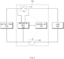
- FIG. 2 is a view showing an environment including a battery management apparatus, according to an embodiment disclosed herein.
- the battery management apparatus 100 may include a first relay 110, a second relay 120, a measuring unit 130, and a controller 140.
- the battery pack 200 may be substantially the same as the battery pack 1 of FIG. 1 .
- the battery management apparatus 100 may be included in the battery pack 200 and may be another device outside the battery pack 200.
- the first relay 110 may connect the battery module 200 with the load 300.
- the first relay 110 may be a positive relay or a main relay.
- an operation of the first relay 110 may be controlled by the controller 140.
- the first relay 110 may include a BJT or a MOSFET.
- the second relay 120 may be different from the first relay 110, and may connect the battery pack 200 with the load 300.
- the second relay 120 may be a negative relay.
- an operation of the second relay 120 may be controlled by the controller 140.
- the second relay 120 may include a BJT or a MOSFET.
- the measuring unit 130 may measure voltages of the battery pack 200 and the load 300.
- the measuring unit 130 may include an analog-to-digital converter (ADC).
- ADC analog-to-digital converter
- the measuring unit 130 may be located outside the battery pack 200.
- the measuring unit 130 may measure the voltage of the battery pack 200 after lowering the voltage.
- the measuring unit 130 may be located outside the battery pack 200.
- the controller 140 may control operations of the first relay 110 and the second relay 120.
- the controller 140 may generate control signals for controlling the operations of the first relay 110 and the second relay 120 to control the operations of the first relay 110 and the second relay 120.
- the controller 140 may obtain a voltage of the battery pack 200 or a voltage of the load 300 based on the operations of the first relay 110 and the second relay 120. For example, the controller 140 may obtain the voltage of the battery pack 200 when both the first relay 110 and the second relay 120 are opened. According to an embodiment, the controller 140 may open both the first relay 110 and the second relay 120, and obtain the voltage of the battery pack 200 through the measuring unit 130.
- the controller 140 may obtain the voltage of the load 300 when the first relay 110 is opened and the second relay 120 is short-circuited.
- the controller 140 may open the first relay 110 and short-circuit the second relay 120, and obtain the voltage of the load 300 through the measuring unit 130. That is, when the second relay 120 is short-circuited, grounds of the battery pack 200 and the load 300 may be matched to each other, such that the measuring unit 130 may measure the voltage of the load 300 under the same condition as the voltage of the battery pack 200, and the controller 140 may obtain the voltage of the load 300 measured by the measuring unit 130.
- the controller 140 may match the ground of the load 300 with the ground of the battery pack 200 by short-circuiting the second relay 120.
- the controller 140 may diagnose that abnormality has occurred in the connectivity of the battery pack 200, when the obtained voltage of the battery pack 200 is less than a first set value. For example, when abnormality occurs in the connectivity of the battery pack 200, a lower voltage value than an existing voltage value of the battery pack 200 may be obtained, such that the controller 140 may diagnose that abnormality has occurred in the connectivity of the battery pack 200.
- the controller 140 may diagnose that abnormality has occurred in the connectivity of the battery pack 300, when the obtained voltage of the load 300 exceeds a second set value. For example, when abnormality occurs in the connectivity of the load 300, a higher voltage value than an existing voltage value applied to the load 300 may be obtained, such that the controller 140 may diagnose that abnormality has occurred in the connectivity of the load 300.
- the controller 140 may diagnose the connectivity of the battery pack 200 and the connectivity of the load 300 before short-circuiting both the first relay 110 and the second relay 120. For example, the controller 140 may open both the first relay 110 and the second relay 120 to diagnose the connectivity of the battery pack 200, short-circuit the second relay 120 to diagnose the connectivity of the load 300, and determine whether to connect the battery pack 200 to the load 300 based on a connectivity diagnosis result of the battery pack 200 and a connectivity diagnosis result of the load 300. In another example, the controller 140 may short-circuit both the first relay 110 and the second relay 120 to connect the battery pack 200 to the load 300 when both the connectivity diagnosis result of the battery pack 200 and the connectivity diagnosis result of the load 300 are normal.
- the measuring unit 130 and the battery pack 200 may form a closed circuit.
- the measuring unit 130 and the load 300 may form a closed circuit.
- the battery management apparatus may diagnose connectivity of a battery pack side and connectivity of a load side.
- the battery management apparatus may measure a battery pack-side voltage and a load-side voltage through one ADC, and diagnose the connectivity of the battery pack side and the load side voltage based on the measured voltages.
- FIG. 3 shows an example of measuring a voltage of a battery pack according to an embodiment disclosed herein.
- the battery management apparatus 100 may measure a voltage at a battery pack 200 side and obtain the measured voltage.
- a controller (the controller 140 of FIG. 2 ) may open both the first relay 110 and the second relay 120, the voltage of the battery pack 200 may be measured through an ADC 131, and the measured voltage may be obtained by the controller (the controller 140 of FIG. 2 ).
- FIG. 4 shows an example of measuring a voltage on a load side according to an embodiment disclosed herein.
- the battery management apparatus 100 may measure a voltage at a load 300 side and obtain the measured voltage.
- the controller (the controller 140 of FIG. 2 ) may open the first relay 110 and short-circuit the second relay 120, the voltage of the load 300 may be measured through the ADC 131, and the measured voltage may be obtained by the controller (the controller 140 of FIG. 2 ).
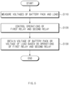
- FIG. 5 is a flowchart of an operating method of a battery management apparatus according to an embodiment disclosed herein.
- an operating method of the battery management apparatus 100 may include operation S 110 of measuring voltages of a battery pack and a load, operation S120 of controlling operations of a first relay and a second relay, and operation S130 of obtaining the voltage of the battery pack or the voltage of the load based on the operations of the first relay and the second relay.
- operations shown in FIG. 5 may be performed by the battery management apparatus 100 of FIG. 2 .
- the controller 140 may control the operations of the first relay 110 and the second relay 120.
- the controller 140 may generate control signals for controlling the operations of the first relay 110 and the second relay 120 to control the operations of the first relay 110 and the second relay 120.
- the controller 140 may obtain the voltage of the battery pack or the voltage of the load based on the operations of the first relay 110 and the second relay 120. For example, the controller 140 may obtain the voltage of the battery pack when the first relay 110 and the second relay 120 are opened. In another example, the controller 140 may obtain the voltage of the load when the first relay 110 is opened and the second relay 120 is short-circuited. According to an embodiment, the controller 140 may control the operations of the first relay 110 and the second relay 120, and obtain the voltage of the battery pack or the voltage of the load based on the operations of the first relay 110 and the second relay 120.
- FIG. 6 is a flowchart showing an operating method of a battery management apparatus, according to an embodiment disclosed herein.
- an operating method of the battery management apparatus 100 may further include operation S210 of diagnosing connectivity of the battery pack based on the voltage of the battery pack and operation S220 of diagnosing connectivity of the load based on the voltage of the load.
- the controller 140 may diagnose the connectivity of the battery pack based on the voltage of the battery pack obtained from the measuring unit 130. According to an embodiment, the controller 140 may diagnose that abnormality has occurred in the connectivity of the battery pack, when the obtained voltage of the battery pack is less than a first set value. According to an embodiment, when abnormality occurs in the connectivity of the battery pack, a lower voltage value than an existing voltage value of the battery pack may be obtained, such that the controller 140 may diagnose that abnormality has occurred in the connectivity of the battery pack.
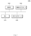
- FIG. 7 is a block diagram showing a hardware configuration of a computing system for performing an operating method of a battery management apparatus, according to an embodiment disclosed herein.
- a computing system 1000 may include an MCU 1010, a memory 1020, an input/output I/F 1030, and a communication I/F 1040.
- the memory 1020 may store various programs regarding log information collection and diagnosis of the battery, etc.
- the memory 1020 may store various information such as a current and a voltage of the battery, the voltage of the battery pack, the voltage of the load, etc.
- the memory 1020 may be provided in plural, depending on a need.
- the memory 1020 may be volatile memory or non-volatile memory.
- RAM random access memory
- DRAM dynamic RAM
- SRAM static RAM
- ROM read only memory
- PROM programmable ROM
- EAROM electrically alterable ROM
- EPROM erasable PROM
- EEPROM electrically erasable PROM
- flash memory etc.
- the above-listed examples of the memory 1020 are merely examples and are not limited thereto.
- the input/output I/F 1030 may provide an interface for transmitting and receiving data by connecting an input device (not shown) such as a keyboard, a mouse, a touch panel, etc., and an output device such as a display (not shown), etc., to the MCU 1010.
- an input device such as a keyboard, a mouse, a touch panel, etc.
- an output device such as a display (not shown), etc.
- the communication I/F 1040 which is a component capable of transmitting and receiving various data to and from a server, may be various devices capable of supporting wired or wireless communication.
- the battery management apparatus may transmit and receive a relay control program or information such as a voltage and a current of various battery packs and the voltage of the load from an external server separately provided through the communication I/F 1040.
- a computer program according to an embodiment disclosed herein may be recorded in the memory 1020 and processed by the MCU 1010, thus being implemented as a module that performs functions shown in FIG. 2 .
Landscapes
- Physics & Mathematics (AREA)
- General Physics & Mathematics (AREA)
- Engineering & Computer Science (AREA)
- Manufacturing & Machinery (AREA)
- Chemical & Material Sciences (AREA)
- Chemical Kinetics & Catalysis (AREA)
- Electrochemistry (AREA)
- General Chemical & Material Sciences (AREA)
- Power Engineering (AREA)
- Life Sciences & Earth Sciences (AREA)
- Sustainable Development (AREA)
- Sustainable Energy (AREA)
- Transportation (AREA)
- Mechanical Engineering (AREA)
- Secondary Cells (AREA)
- Charge And Discharge Circuits For Batteries Or The Like (AREA)
- Testing Electric Properties And Detecting Electric Faults (AREA)
Abstract
Description
- This application claims priority to and the benefit of
Korean Patent Application No. 10-2022-0021121 filed in the Korean Intellectual Property Office on February 17, 2022 - Embodiments disclosed herein relate to a battery management apparatus and an operating method thereof.
- Recently, research and development of secondary batteries have been actively performed. Herein, the secondary batteries, which are chargeable/dischargeable batteries, may include all of conventional nickel (Ni)/cadmium (Cd) batteries, Ni/metal hydride (MH) batteries, etc., and recent lithium-ion batteries. Among the secondary batteries, a lithium-ion battery has a much higher energy density than those of the conventional Ni/Cd batteries, Ni/MH batteries, etc. Moreover, the lithium-ion battery may be manufactured to be small and lightweight, such that the lithium-ion battery has been used as a power source of mobile devices, and recently, a use range thereof has been extended to power sources for electric vehicles, attracting attention as next-generation energy storage media.
- For a battery, safety has to be increased by preventing fire occurrence. International functional safety has been distributed to prevent accidents caused by functional errors in electrical or electronic devices including batteries, and a device including a battery may need various diagnosis circuits or software to satisfy various standards.
- Embodiments disclosed herein aim to provide a battery management apparatus and an operating method thereof in which connectivity of an inside of a battery pack and a connectivity of a load may be diagnosed.
- Embodiments disclosed herein aim to provide a battery management apparatus and an operating method thereof in which both connectivity of a battery pack side and connectivity of a load side may be diagnosed with one voltage measuring device.
- Technical problems of the embodiments disclosed herein are not limited to the above-described technical problems, and other unmentioned technical problems would be clearly understood by one of ordinary skill in the art from the following description.
- A battery management apparatus according to an embodiment disclosed herein includes a first relay configured to connect an end of a battery pack to an end of a load, a second relay configured to connect the other end of the battery pack to the other end of the load, a measuring unit configured to measure voltages of the battery pack and the load, and a controller configured to control operations of the first relay and the second relay and obtain the voltage of the battery pack or the voltage of the load based on the operations of the first relay and the second relay.
- In an embodiment, the controller may be further configured to obtain the voltage of the battery pack when both the first relay and the second relay are opened.
- In an embodiment, the controller may be further configured to open the first relay, short-circuit the second relay, and obtain the voltage of the load.
- In an embodiment, the measuring unit may further include an analog-to-digital converter (ADC).
- In an embodiment, the controller may be further configured to diagnose connectivity of the battery pack based on the voltage of the battery pack and diagnose connectivity of the load based on the voltage of the load.
- In an embodiment, the measuring unit may be located outside the battery pack.
- In an embodiment, the first relay may be a positive relay, and the second relay may be a negative relay.
- In an embodiment, the controller may be further configured to match a ground of the load to a ground of the battery pack by short-circuiting the second relay.
- In an embodiment, the controller may be further configured to diagnose connectivity of the battery pack by opening both the first relay and the second relay, diagnose connectivity of the load by short-circuiting the second relay, and short-circuit both the first relay and the second relay when a connectivity diagnosis result of the battery pack and a connectivity diagnosis result of the load are normal.
- In an embodiment, the measuring unit and the battery pack may form a closed circuit when both the first relay and the second relay are opened.
- In an embodiment, the measuring unit and the load may form a closed circuit when the first relay is opened and the second relay is short-circuited.
- An operating method of a battery management apparatus according to an embodiment disclosed herein includes measuring voltages of the battery pack and the load, controlling operations of a first relay and a second relay, and obtaining the voltage of the battery pack or the voltage of the load based on the operations of the first relay and the second relay, in which the first relay and the second relay connect the battery pack to the load.
- In an embodiment, the obtaining of the voltage of the battery pack or the voltage of the load based on the operations of the first relay and the second relay may include obtaining the voltage of the battery pack when the first relay is opened and the second relay is opened.
- In an embodiment, the obtaining of the voltage of the battery pack or the voltage of the load based on the operations of the first relay and the second relay may include obtaining the voltage of the load when the first relay is opened and the second relay is short-circuited.
- In an embodiment, the operating method may further include diagnosing connectivity of the battery pack based on the voltage of the battery pack and diagnosing connectivity of the load based on the voltage of the load.
- The battery management apparatus and the operating method thereof according to an embodiment disclosed herein may diagnose connectivity of a battery pack side and connectivity of a load side.
- The battery management apparatus and the operating method thereof according to an embodiment disclosed herein may measure a battery pack-side voltage and a load-side voltage through one ADC, and diagnose the connectivity of the battery pack side and the load side voltage based on the measured voltages.
- The battery management apparatus and the operating method thereof according to an embodiment disclosed herein may diagnose the connectivity of the both sides with a simplified circuit by matching grounds of the battery pack side and the load side.
- Moreover, various effects recognized directly or indirectly from the disclosure may be provided.
-
-
FIG. 1 is a block diagram of a general battery pack. -
FIG. 2 is a view showing an environment including a battery management apparatus, according to an embodiment disclosed herein. -
FIG. 3 shows an example of measuring a voltage of a battery pack according to an embodiment disclosed herein. -
FIG. 4 shows an example of measuring a voltage on a load side according to an embodiment disclosed herein. -
FIG. 5 is a flowchart of an operating method of a battery management apparatus according to an embodiment disclosed herein. -
FIG. 6 is a flowchart showing an operating method of a battery management apparatus, according to an embodiment disclosed herein. -
FIG. 7 is a block diagram showing a hardware configuration of a computing system for performing an operating method of a battery management apparatus, according to an embodiment disclosed herein. - Hereinafter, embodiments disclosed in this document will be described in detail with reference to the exemplary drawings. In adding reference numerals to components of each drawing, it should be noted that the same components are given the same reference numerals even though they are indicated in different drawings. In addition, in describing the embodiments disclosed in this document, when it is determined that a detailed description of a related known configuration or function interferes with the understanding of an embodiment disclosed in this document, the detailed description thereof will be omitted.
- To describe a component of an embodiment disclosed herein, terms such as first, second, A, B, (a), (b), etc., may be used. These terms are used merely for distinguishing one component from another component and do not limit the component to the essence, sequence, order, etc., of the component. The terms used herein, including technical and scientific terms, have the same meanings as terms that are generally understood by those skilled in the art, as long as the terms are not differently defined. Generally, the terms defined in a generally used dictionary should be interpreted as having the same meanings as the contextual meanings of the relevant technology and should not be interpreted as having ideal or exaggerated meanings unless they are clearly defined in the present application.
-
FIG. 1 is a block diagram of a general battery pack. - Referring to
FIG. 1 , a battery control system including abattery pack 1 and a higher-level controller 2 included in a higher-level system according to an embodiment of the present disclosure is schematically shown. - As shown in
FIG. 1 , thebattery pack 1 may include abattery module 10 that includes one or more battery cells and is chargeable/dischargeable, aswitching unit 14 serially connected to a positive (+) terminal side or a negative (-) terminal side of thebattery module 10 to control a charging/discharging current flow of thebattery module 10, and a battery management system (e.g., RBMS) 20 for control and management to prevent over-charging and over-discharging by monitoring a voltage, a current, a temperature, etc., of thebattery pack 1. Thebattery pack 1 may include thebattery module 10, thesensor 12, theswitching unit 14, and thebattery management system 20 provided in plural. - Herein, as the
switching unit 14 which is an element for controlling a current flow for charging or discharging of the plurality ofbattery modules 10, for example, at least one relay, magnetic contactor, etc., may be used according to specifications of thebattery pack 1. - The
battery management system 20, which is an interface for receiving measurement values of the above-described various parameter values, may include a plurality of terminals and a circuit, etc., connected thereto to process input values. Thebattery management system 20 may control on/off of theswitching unit 14, e.g., a relay, a contactor, etc., and may be connected to thebattery module 10 to monitor the state of eachbattery module 10. According to an embodiment, thebattery management system 20 may include abattery management apparatus 100 ofFIG. 2 . According to another embodiment, thebattery management system 20 may be different from thebattery management apparatus 100 ofFIG. 2 . That is, thebattery management apparatus 100 ofFIG. 2 may be included in thebattery pack 1 and may be configured as another device outside thebattery pack 1. - The higher-
level controller 2 may transmit a control signal regarding thebattery module 10 to thebattery management system 20. Thus, thebattery management system 20 may also be controlled in terms of an operation thereof based on a signal applied from the higher-level controller 2. -
FIG. 2 is a view showing an environment including a battery management apparatus, according to an embodiment disclosed herein. - Referring to
FIG. 2 , thebattery management apparatus 100 according to an embodiment disclosed herein may include afirst relay 110, asecond relay 120, a measuringunit 130, and acontroller 140. According to an embodiment, thebattery pack 200 may be substantially the same as thebattery pack 1 ofFIG. 1 . According another embodiment, thebattery management apparatus 100 may be included in thebattery pack 200 and may be another device outside thebattery pack 200. - The
first relay 110 may connect thebattery module 200 with theload 300. For example, thefirst relay 110 may be a positive relay or a main relay. According to an embodiment, an operation of thefirst relay 110 may be controlled by thecontroller 140. According to an embodiment, thefirst relay 110 may include a BJT or a MOSFET. - The
second relay 120 may be different from thefirst relay 110, and may connect thebattery pack 200 with theload 300. For example, thesecond relay 120 may be a negative relay. According to an embodiment, an operation of thesecond relay 120 may be controlled by thecontroller 140. According to an embodiment, thesecond relay 120 may include a BJT or a MOSFET. - The measuring
unit 130 may measure voltages of thebattery pack 200 and theload 300. For example, the measuringunit 130 may include an analog-to-digital converter (ADC). - Depending on an embodiment, the measuring
unit 130 may be located outside thebattery pack 200. For example, as the voltage of thebattery pack 200 is high, the measuringunit 130 may measure the voltage of thebattery pack 200 after lowering the voltage. In another example, to lower the voltage of thebattery pack 200 and apply the voltage to the measuringunit 130, the measuringunit 130 may be located outside thebattery pack 200. - The
controller 140 may control operations of thefirst relay 110 and thesecond relay 120. For example, thecontroller 140 may generate control signals for controlling the operations of thefirst relay 110 and thesecond relay 120 to control the operations of thefirst relay 110 and thesecond relay 120. - The
controller 140 may obtain a voltage of thebattery pack 200 or a voltage of theload 300 based on the operations of thefirst relay 110 and thesecond relay 120. For example, thecontroller 140 may obtain the voltage of thebattery pack 200 when both thefirst relay 110 and thesecond relay 120 are opened. According to an embodiment, thecontroller 140 may open both thefirst relay 110 and thesecond relay 120, and obtain the voltage of thebattery pack 200 through the measuringunit 130. - According to an embodiment, the
controller 140 may obtain the voltage of theload 300 when thefirst relay 110 is opened and thesecond relay 120 is short-circuited. For example, thecontroller 140 may open thefirst relay 110 and short-circuit thesecond relay 120, and obtain the voltage of theload 300 through the measuringunit 130. That is, when thesecond relay 120 is short-circuited, grounds of thebattery pack 200 and theload 300 may be matched to each other, such that the measuringunit 130 may measure the voltage of theload 300 under the same condition as the voltage of thebattery pack 200, and thecontroller 140 may obtain the voltage of theload 300 measured by the measuringunit 130. According to an embodiment, thecontroller 140 may match the ground of theload 300 with the ground of thebattery pack 200 by short-circuiting thesecond relay 120. - The
controller 140 may diagnose connectivity of thebattery pack 200 or theload 300 based on the obtained voltage of thebattery pack 200 or the obtained voltage of theload 300. For example, thecontroller 140 may diagnose connectivity of thebattery pack 200 based on the obtained voltage of thebattery pack 200. In another example, thecontroller 140 may diagnose connectivity of theload 300 based on the obtained voltage of thebattery pack 300. - According to an embodiment, the
controller 140 may diagnose that abnormality has occurred in the connectivity of thebattery pack 200, when the obtained voltage of thebattery pack 200 is less than a first set value. For example, when abnormality occurs in the connectivity of thebattery pack 200, a lower voltage value than an existing voltage value of thebattery pack 200 may be obtained, such that thecontroller 140 may diagnose that abnormality has occurred in the connectivity of thebattery pack 200. - According to an embodiment, the
controller 140 may diagnose that abnormality has occurred in the connectivity of thebattery pack 300, when the obtained voltage of theload 300 exceeds a second set value. For example, when abnormality occurs in the connectivity of theload 300, a higher voltage value than an existing voltage value applied to theload 300 may be obtained, such that thecontroller 140 may diagnose that abnormality has occurred in the connectivity of theload 300. - According to an embodiment, the
controller 140 may diagnose the connectivity of thebattery pack 200 and the connectivity of theload 300 before short-circuiting both thefirst relay 110 and thesecond relay 120. For example, thecontroller 140 may open both thefirst relay 110 and thesecond relay 120 to diagnose the connectivity of thebattery pack 200, short-circuit thesecond relay 120 to diagnose the connectivity of theload 300, and determine whether to connect thebattery pack 200 to theload 300 based on a connectivity diagnosis result of thebattery pack 200 and a connectivity diagnosis result of theload 300. In another example, thecontroller 140 may short-circuit both thefirst relay 110 and thesecond relay 120 to connect thebattery pack 200 to theload 300 when both the connectivity diagnosis result of thebattery pack 200 and the connectivity diagnosis result of theload 300 are normal. In another example, thecontroller 140 may not connect thebattery pack 200 to theload 300 when at least any one of the connectivity diagnosis result of thebattery pack 200 and the connectivity diagnosis result of theload 300 is not normal. In this case, thecontroller 140 may transmit information about the connectivity of thebattery pack 200 or the connectivity of theload 300 to an external device (e.g., the higher-level controller 2 ofFIG. 1 ) or provide, to a user, information indicating that abnormality has occurred in the connectivity of thebattery pack 200 or the connectivity of theload 300. - According to an embodiment, when both the
first relay 110 and thesecond relay 120 are opened, the measuringunit 130 and thebattery pack 200 may form a closed circuit. - According to an embodiment, when the
first relay 110 is opened and thesecond relay 120 is short-circuited, the measuringunit 130 and theload 300 may form a closed circuit. - The battery management apparatus according to an embodiment disclosed herein may diagnose connectivity of a battery pack side and connectivity of a load side.
- The battery management apparatus according to an embodiment disclosed herein may measure a battery pack-side voltage and a load-side voltage through one ADC, and diagnose the connectivity of the battery pack side and the load side voltage based on the measured voltages.
- The battery management apparatus according to an embodiment disclosed herein may diagnose the connectivity of the both sides with a simplified circuit by matching grounds of the battery pack side and the load side.
-
FIG. 3 shows an example of measuring a voltage of a battery pack according to an embodiment disclosed herein. - Referring to
FIG. 3 , thebattery management apparatus 100 according to an embodiment disclosed herein may measure a voltage at abattery pack 200 side and obtain the measured voltage. - According to an embodiment, a controller (the
controller 140 ofFIG. 2 ) may open both thefirst relay 110 and thesecond relay 120, the voltage of thebattery pack 200 may be measured through anADC 131, and the measured voltage may be obtained by the controller (thecontroller 140 ofFIG. 2 ). -
FIG. 4 shows an example of measuring a voltage on a load side according to an embodiment disclosed herein. - Referring to
FIG. 4 , thebattery management apparatus 100 according to an embodiment disclosed herein may measure a voltage at aload 300 side and obtain the measured voltage. - According to an embodiment, the controller (the
controller 140 ofFIG. 2 ) may open thefirst relay 110 and short-circuit thesecond relay 120, the voltage of theload 300 may be measured through theADC 131, and the measured voltage may be obtained by the controller (thecontroller 140 ofFIG. 2 ). -
FIG. 5 is a flowchart of an operating method of a battery management apparatus according to an embodiment disclosed herein. - Referring to
FIG. 5 , an operating method of thebattery management apparatus 100 according to an embodiment disclosed herein may includeoperation S 110 of measuring voltages of a battery pack and a load, operation S120 of controlling operations of a first relay and a second relay, and operation S130 of obtaining the voltage of the battery pack or the voltage of the load based on the operations of the first relay and the second relay. According to an embodiment, operations shown inFIG. 5 may be performed by thebattery management apparatus 100 ofFIG. 2 . - In
operation S 110 of measuring the voltages of the battery pack and the load, the measuringunit 130 may measure the voltages of the battery pack and the load. For example, the measuringunit 130 may include an ADC. - In operation S120 of controlling the operations of the first relay and the second relay, the
controller 140 may control the operations of thefirst relay 110 and thesecond relay 120. For example, thecontroller 140 may generate control signals for controlling the operations of thefirst relay 110 and thesecond relay 120 to control the operations of thefirst relay 110 and thesecond relay 120. - In operation S130 of obtaining the voltage of the battery pack or the voltage of the load based on the operations of the first relay and the second relay, the
controller 140 may obtain the voltage of the battery pack or the voltage of the load based on the operations of thefirst relay 110 and thesecond relay 120. For example, thecontroller 140 may obtain the voltage of the battery pack when thefirst relay 110 and thesecond relay 120 are opened. In another example, thecontroller 140 may obtain the voltage of the load when thefirst relay 110 is opened and thesecond relay 120 is short-circuited. According to an embodiment, thecontroller 140 may control the operations of thefirst relay 110 and thesecond relay 120, and obtain the voltage of the battery pack or the voltage of the load based on the operations of thefirst relay 110 and thesecond relay 120. -
FIG. 6 is a flowchart showing an operating method of a battery management apparatus, according to an embodiment disclosed herein. - Referring to
FIG. 6 , an operating method of thebattery management apparatus 100 according to an embodiment disclosed herein may further include operation S210 of diagnosing connectivity of the battery pack based on the voltage of the battery pack and operation S220 of diagnosing connectivity of the load based on the voltage of the load. - In operation S210 of diagnosing the connectivity of the battery pack based on the voltage of the battery pack, the
controller 140 may diagnose the connectivity of the battery pack based on the voltage of the battery pack obtained from the measuringunit 130. According to an embodiment, thecontroller 140 may diagnose that abnormality has occurred in the connectivity of the battery pack, when the obtained voltage of the battery pack is less than a first set value. According to an embodiment, when abnormality occurs in the connectivity of the battery pack, a lower voltage value than an existing voltage value of the battery pack may be obtained, such that thecontroller 140 may diagnose that abnormality has occurred in the connectivity of the battery pack. - In operation S220 of diagnosing the connectivity of the load based on the voltage of the load, the
controller 140 may diagnose the connectivity of the load based on the voltage of the load obtained from the measuringunit 130. For example, thecontroller 140 may diagnose that abnormality has occurred in the connectivity of the load, when the obtained voltage of the load exceeds a second set value. According to an embodiment, when abnormality occurs in the connectivity of the load, a higher voltage value than an existing voltage value applied to the load may be obtained, such that thecontroller 140 may diagnose that abnormality has occurred in the connectivity of the load. -
FIG. 7 is a block diagram showing a hardware configuration of a computing system for performing an operating method of a battery management apparatus, according to an embodiment disclosed herein. - Referring to
FIG. 7 , acomputing system 1000 according to an embodiment disclosed herein may include anMCU 1010, amemory 1020, an input/output I/F 1030, and a communication I/F 1040. - The
MCU 1010 may be a processor that executes various programs (e.g., a battery pack voltage or current collection program, a relay control program, a connectivity diagnosis program of a battery pack or load, etc.) stored in thememory 1020, processes various information including a voltage of a battery pack and a voltage of a load through these programs, and executes the above-described functions of the battery management apparatus shown inFIG. 2 . - The
memory 1020 may store various programs regarding log information collection and diagnosis of the battery, etc. Thememory 1020 may store various information such as a current and a voltage of the battery, the voltage of the battery pack, the voltage of the load, etc. - The
memory 1020 may be provided in plural, depending on a need. Thememory 1020 may be volatile memory or non-volatile memory. For thememory 1020 as the volatile memory, random access memory (RAM), dynamic RAM (DRAM), static RAM (SRAM), etc., may be used. For thememory 1020 as the nonvolatile memory, read only memory (ROM), programmable ROM (PROM), electrically alterable ROM (EAROM), erasable PROM (EPROM), electrically erasable PROM (EEPROM), flash memory, etc., may be used. The above-listed examples of thememory 1020 are merely examples and are not limited thereto. - The input/output I/
F 1030 may provide an interface for transmitting and receiving data by connecting an input device (not shown) such as a keyboard, a mouse, a touch panel, etc., and an output device such as a display (not shown), etc., to theMCU 1010. - The communication I/
F 1040, which is a component capable of transmitting and receiving various data to and from a server, may be various devices capable of supporting wired or wireless communication. For example, the battery management apparatus may transmit and receive a relay control program or information such as a voltage and a current of various battery packs and the voltage of the load from an external server separately provided through the communication I/F 1040. - As such, a computer program according to an embodiment disclosed herein may be recorded in the
memory 1020 and processed by theMCU 1010, thus being implemented as a module that performs functions shown inFIG. 2 . - The above description is merely illustrative of the technical idea of the present disclosure, and various modifications and variations will be possible without departing from the essential characteristics of embodiments of the present disclosure by those of ordinary skill in the art to which the embodiments disclosed herein pertains.
- Therefore, the embodiments disclosed herein are intended for description rather than limitation of the technical spirit of the embodiments disclosed herein and the scope of the technical spirit of the present disclosure is not limited by these embodiments disclosed herein. The protection scope of the technical spirit disclosed herein should be interpreted by the following claims, and all technical spirits within the same range should be understood to be included in the range of the present disclosure.
Claims (15)
- A battery management apparatus comprising:a first relay configured to connect an end of a battery pack to an end of a load;a second relay configured to connect the other end of the battery pack to the other end of the load;a measuring unit configured to measure voltages of the battery pack and the load; anda controller configured to control operations of the first relay and the second relay and obtain the voltage of the battery pack or the voltage of the load based on the operations of the first relay and the second relay.
- The battery management apparatus of claim 1, wherein the controller is further configured to obtain the voltage of the battery pack when both the first relay and the second relay are opened.
- The battery management apparatus of claim 1, wherein the controller is further configured to open the first relay, short-circuit the second relay, and obtain the voltage of the load.
- The battery management apparatus of claim 1, wherein the measuring unit comprises an analog-to-digital converter (ADC).
- The battery management apparatus of claim 1, wherein the controller is further configured to:diagnose connectivity of the battery pack based on the voltage of the battery pack; anddiagnose connectivity of the load based on the voltage of the load.
- The battery management apparatus of claim 1, wherein the measuring unit is located outside the battery pack.
- The battery management apparatus of claim 1, wherein the first relay is a positive relay, and the second relay is a negative relay.
- The battery management apparatus of claim 1, wherein the controller is further configured to match a ground of the load to a ground of the battery pack by short-circuiting the second relay.
- The battery management apparatus of claim 1, wherein the controller is further configured to:diagnose connectivity of the battery pack by opening both the first relay and the second relay;diagnose connectivity of the load by short-circuiting the second relay; andshort-circuit both the first relay and the second relay when a connectivity diagnosis result of the battery pack and a connectivity diagnosis result of the load are normal.
- The battery management apparatus of claim 1, wherein the measuring unit and the battery pack form a closed circuit when both the first relay and the second relay are opened.
- The battery management apparatus of claim 1, wherein the measuring unit and the load form a closed circuit when the first relay is opened and the second relay is short-circuited.
- An operating method of a battery management apparatus, the operating method:measuring voltages of the battery pack and the load;controlling operations of a first relay and a second relay; andobtaining the voltage of the battery pack or the voltage of the load based on the operations of the first relay and the second relay,wherein the first relay and the second relay connect the battery pack to the load.
- The operating method of claim 12, wherein the obtaining of the voltage of the battery pack or the voltage of the load based on the operations of the first relay and the second relay comprises obtaining the voltage of the battery pack when the first relay is opened and the second relay is opened.
- The operating method of claim 12, wherein the obtaining of the voltage of the battery pack or the voltage of the load based on the operations of the first relay and the second relay comprises obtaining the voltage of the load when the first relay is opened and the second relay is short-circuited.
- The operating method of claim 12, further comprising:diagnosing connectivity of the battery pack based on the voltage of the battery pack; anddiagnosing connectivity of the load based on the voltage of the load.
Applications Claiming Priority (2)
| Application Number | Priority Date | Filing Date | Title |
|---|---|---|---|
| KR1020220021121A KR102916571B1 (en) | 2022-02-17 | 2022-02-17 | Battery management apparatus and operating method of the same |
| PCT/KR2023/000509 WO2023158106A1 (en) | 2022-02-17 | 2023-01-11 | Battery management apparatus and operation method therefor |
Publications (2)
| Publication Number | Publication Date |
|---|---|
| EP4481415A1 true EP4481415A1 (en) | 2024-12-25 |
| EP4481415A4 EP4481415A4 (en) | 2025-08-06 |
Family
ID=87578807
Family Applications (1)
| Application Number | Title | Priority Date | Filing Date |
|---|---|---|---|
| EP23756519.7A Pending EP4481415A4 (en) | 2022-02-17 | 2023-01-11 | BATTERY MANAGEMENT DEVICE AND OPERATING METHOD THEREFOR |
Country Status (6)
| Country | Link |
|---|---|
| US (1) | US20250149663A1 (en) |
| EP (1) | EP4481415A4 (en) |
| JP (1) | JP2025506204A (en) |
| KR (1) | KR102916571B1 (en) |
| CN (1) | CN118715446A (en) |
| WO (1) | WO2023158106A1 (en) |
Family Cites Families (17)
| Publication number | Priority date | Publication date | Assignee | Title |
|---|---|---|---|---|
| US8570047B1 (en) * | 2009-02-12 | 2013-10-29 | The United States Of America As Represented By The Administrator Of The National Aeronautics And Space Administration | Battery fault detection with saturating transformers |
| CN103917884B (en) * | 2011-11-08 | 2016-08-24 | 新神户电机株式会社 | Accumulator state monitoring system |
| KR101487577B1 (en) * | 2012-02-02 | 2015-01-29 | 주식회사 엘지화학 | Method and apparatus for detecting default of battery pack, and power relay assembly thereof |
| KR101440531B1 (en) * | 2012-07-09 | 2014-09-17 | 주식회사 엘지화학 | Apparatus and method for diagnosis of electric contactor |
| DE102012213159A1 (en) * | 2012-07-26 | 2014-01-30 | Robert Bosch Gmbh | Battery system with battery contactors and a diagnostic device for monitoring the functional status of the contactors and the associated diagnostic procedure |
| KR102052956B1 (en) * | 2013-05-21 | 2019-12-09 | 엘지이노텍 주식회사 | Relay checking device of battery pack and Battery control system |
| JP2015053825A (en) * | 2013-09-09 | 2015-03-19 | 矢崎総業株式会社 | Vehicle power supply system |
| US9146281B2 (en) * | 2013-11-12 | 2015-09-29 | Ford Global Technologies, Llc | Electric vehicle battery contactor switch monitoring |
| KR102042756B1 (en) * | 2016-10-10 | 2019-11-08 | 주식회사 엘지화학 | Diagnostic appratus and power system including the same |
| CN114325412B (en) * | 2017-03-20 | 2024-12-06 | 深圳引望智能技术有限公司 | A detection circuit, method and device |
| KR102204983B1 (en) * | 2017-09-25 | 2021-01-18 | 주식회사 엘지화학 | Apparatus for managing battery, battery pack including the same and vehicle including the same |
| KR102056876B1 (en) * | 2017-09-25 | 2019-12-17 | 주식회사 엘지화학 | Apparatus for managing battery, battery pack including the same and vehicle including the same |
| KR102291762B1 (en) * | 2017-11-07 | 2021-09-03 | 주식회사 엘지에너지솔루션 | Circuit for diagnosing a relay |
| KR102785104B1 (en) * | 2019-12-20 | 2025-03-21 | 주식회사 엘지에너지솔루션 | Apparatus and method for diagnosing parallel battery relay |
| JP7365962B2 (en) * | 2020-05-12 | 2023-10-20 | 株式会社クボタ | battery unit |
| KR20220012044A (en) * | 2020-07-22 | 2022-02-03 | 주식회사 엘지에너지솔루션 | Battery apparatus, battery management system, and method of diagonsing supply voltage of contactor |
| KR102411507B1 (en) | 2020-08-13 | 2022-06-21 | 한국화학연구원 | Amorphous super engineering plastic fiber and method for manufacturing the same |
-
2022
- 2022-02-17 KR KR1020220021121A patent/KR102916571B1/en active Active
-
2023
- 2023-01-11 US US18/837,647 patent/US20250149663A1/en active Pending
- 2023-01-11 WO PCT/KR2023/000509 patent/WO2023158106A1/en not_active Ceased
- 2023-01-11 EP EP23756519.7A patent/EP4481415A4/en active Pending
- 2023-01-11 JP JP2024547852A patent/JP2025506204A/en active Pending
- 2023-01-11 CN CN202380021204.0A patent/CN118715446A/en active Pending
Also Published As
| Publication number | Publication date |
|---|---|
| KR102916571B1 (en) | 2026-01-22 |
| JP2025506204A (en) | 2025-03-07 |
| KR20230123838A (en) | 2023-08-24 |
| WO2023158106A1 (en) | 2023-08-24 |
| US20250149663A1 (en) | 2025-05-08 |
| EP4481415A4 (en) | 2025-08-06 |
| CN118715446A (en) | 2024-09-27 |
Similar Documents
| Publication | Publication Date | Title |
|---|---|---|
| US12130338B2 (en) | Battery abnormality diagnosis apparatus and method | |
| US12566214B2 (en) | Battery abnormality diagnosis apparatus and method | |
| EP4102239A1 (en) | Battery management device and method | |
| EP4446760A1 (en) | Apparatus for calculating depth of charge of battery, and operation method thereof | |
| EP4446764A1 (en) | Battery state management device and operation method thereof | |
| EP4692824A1 (en) | Battery management apparatus and operation method therefor | |
| EP4567447A1 (en) | Battery management apparatus and operation method therefor | |
| EP4365613B1 (en) | Battery pack and operating method thereof | |
| EP4564032A1 (en) | Battery management device and operating method thereof | |
| EP4653897A1 (en) | Battery diagnostic device and operation method thereof | |
| EP4600677A1 (en) | Battery pack management device and operation method thereof | |
| US20250149663A1 (en) | Battery Management Apparatus and Operating Method Thereof | |
| EP4325232A1 (en) | Battery management device and operating method therefor | |
| EP4481982A1 (en) | Battery system and battery balancing method thereof | |
| EP4105668A1 (en) | Relay state management device and operation method therefor | |
| EP4600678A1 (en) | Battery management device and operation method therefor | |
| EP4614167A1 (en) | Battery management device, and operation method thereof | |
| EP4692825A1 (en) | Battery management device and operation method thereof | |
| EP4711789A1 (en) | Battery diagnostic device, and operation method therefor | |
| EP4307516A1 (en) | Battery management device and method | |
| US20250298085A1 (en) | Impedance Measurement System And Operating Method Thereof | |
| EP4650803A1 (en) | Battery diagnosis device and operation method thereof | |
| KR20250092893A (en) | Battery diagnosis apparatus and operating method of the same | |
| KR20250097496A (en) | Battery management apparatus and operating method of the same | |
| EP4671798A1 (en) | BATTERY DIAGNOSTIC DEVICE AND OPERATING PROCEDURES |
Legal Events
| Date | Code | Title | Description |
|---|---|---|---|
| STAA | Information on the status of an ep patent application or granted ep patent |
Free format text: STATUS: THE INTERNATIONAL PUBLICATION HAS BEEN MADE |
|
| PUAI | Public reference made under article 153(3) epc to a published international application that has entered the european phase |
Free format text: ORIGINAL CODE: 0009012 |
|
| STAA | Information on the status of an ep patent application or granted ep patent |
Free format text: STATUS: REQUEST FOR EXAMINATION WAS MADE |
|
| 17P | Request for examination filed |
Effective date: 20240808 |
|
| AK | Designated contracting states |
Kind code of ref document: A1 Designated state(s): AL AT BE BG CH CY CZ DE DK EE ES FI FR GB GR HR HU IE IS IT LI LT LU LV MC ME MK MT NL NO PL PT RO RS SE SI SK SM TR |
|
| DAV | Request for validation of the european patent (deleted) | ||
| DAX | Request for extension of the european patent (deleted) | ||
| A4 | Supplementary search report drawn up and despatched |
Effective date: 20250707 |
|
| RIC1 | Information provided on ipc code assigned before grant |
Ipc: G01R 31/392 20190101AFI20250701BHEP Ipc: G01R 31/3835 20190101ALI20250701BHEP Ipc: G01R 19/145 20060101ALI20250701BHEP Ipc: G01R 19/25 20060101ALI20250701BHEP Ipc: B60L 3/00 20190101ALI20250701BHEP |
|
| GRAP | Despatch of communication of intention to grant a patent |
Free format text: ORIGINAL CODE: EPIDOSNIGR1 |
|
| STAA | Information on the status of an ep patent application or granted ep patent |
Free format text: STATUS: GRANT OF PATENT IS INTENDED |
|
| RIC1 | Information provided on ipc code assigned before grant |
Ipc: G01R 31/392 20190101AFI20260325BHEP Ipc: G01R 31/3835 20190101ALI20260325BHEP Ipc: G01R 19/145 20060101ALI20260325BHEP Ipc: G01R 19/25 20060101ALI20260325BHEP Ipc: B60L 3/00 20190101ALI20260325BHEP Ipc: G01R 31/52 20200101ALI20260325BHEP |