EP4481304A1 - Heat source unit - Google Patents
Heat source unit Download PDFInfo
- Publication number
- EP4481304A1 EP4481304A1 EP23752978.9A EP23752978A EP4481304A1 EP 4481304 A1 EP4481304 A1 EP 4481304A1 EP 23752978 A EP23752978 A EP 23752978A EP 4481304 A1 EP4481304 A1 EP 4481304A1
- Authority
- EP
- European Patent Office
- Prior art keywords
- flow path
- refrigerant
- pipe
- refrigerant flow
- module
- Prior art date
- Legal status (The legal status is an assumption and is not a legal conclusion. Google has not performed a legal analysis and makes no representation as to the accuracy of the status listed.)
- Pending
Links
Images




Classifications
-
- F—MECHANICAL ENGINEERING; LIGHTING; HEATING; WEAPONS; BLASTING
- F25—REFRIGERATION OR COOLING; COMBINED HEATING AND REFRIGERATION SYSTEMS; HEAT PUMP SYSTEMS; MANUFACTURE OR STORAGE OF ICE; LIQUEFACTION SOLIDIFICATION OF GASES
- F25B—REFRIGERATION MACHINES, PLANTS OR SYSTEMS; COMBINED HEATING AND REFRIGERATION SYSTEMS; HEAT PUMP SYSTEMS
- F25B41/00—Fluid-circulation arrangements
- F25B41/20—Disposition of valves, e.g. of on-off valves or flow control valves
- F25B41/24—Arrangement of shut-off valves for disconnecting a part of the refrigerant cycle, e.g. an outdoor part
-
- F—MECHANICAL ENGINEERING; LIGHTING; HEATING; WEAPONS; BLASTING
- F25—REFRIGERATION OR COOLING; COMBINED HEATING AND REFRIGERATION SYSTEMS; HEAT PUMP SYSTEMS; MANUFACTURE OR STORAGE OF ICE; LIQUEFACTION SOLIDIFICATION OF GASES
- F25B—REFRIGERATION MACHINES, PLANTS OR SYSTEMS; COMBINED HEATING AND REFRIGERATION SYSTEMS; HEAT PUMP SYSTEMS
- F25B13/00—Compression machines, plants or systems, with reversible cycle
-
- F—MECHANICAL ENGINEERING; LIGHTING; HEATING; WEAPONS; BLASTING
- F25—REFRIGERATION OR COOLING; COMBINED HEATING AND REFRIGERATION SYSTEMS; HEAT PUMP SYSTEMS; MANUFACTURE OR STORAGE OF ICE; LIQUEFACTION SOLIDIFICATION OF GASES
- F25B—REFRIGERATION MACHINES, PLANTS OR SYSTEMS; COMBINED HEATING AND REFRIGERATION SYSTEMS; HEAT PUMP SYSTEMS
- F25B41/00—Fluid-circulation arrangements
- F25B41/20—Disposition of valves, e.g. of on-off valves or flow control valves
-
- F—MECHANICAL ENGINEERING; LIGHTING; HEATING; WEAPONS; BLASTING
- F25—REFRIGERATION OR COOLING; COMBINED HEATING AND REFRIGERATION SYSTEMS; HEAT PUMP SYSTEMS; MANUFACTURE OR STORAGE OF ICE; LIQUEFACTION SOLIDIFICATION OF GASES
- F25B—REFRIGERATION MACHINES, PLANTS OR SYSTEMS; COMBINED HEATING AND REFRIGERATION SYSTEMS; HEAT PUMP SYSTEMS
- F25B41/00—Fluid-circulation arrangements
- F25B41/20—Disposition of valves, e.g. of on-off valves or flow control valves
- F25B41/26—Disposition of valves, e.g. of on-off valves or flow control valves of fluid flow reversing valves
-
- F—MECHANICAL ENGINEERING; LIGHTING; HEATING; WEAPONS; BLASTING
- F25—REFRIGERATION OR COOLING; COMBINED HEATING AND REFRIGERATION SYSTEMS; HEAT PUMP SYSTEMS; MANUFACTURE OR STORAGE OF ICE; LIQUEFACTION SOLIDIFICATION OF GASES
- F25B—REFRIGERATION MACHINES, PLANTS OR SYSTEMS; COMBINED HEATING AND REFRIGERATION SYSTEMS; HEAT PUMP SYSTEMS
- F25B41/00—Fluid-circulation arrangements
- F25B41/30—Expansion means; Dispositions thereof
-
- F—MECHANICAL ENGINEERING; LIGHTING; HEATING; WEAPONS; BLASTING
- F25—REFRIGERATION OR COOLING; COMBINED HEATING AND REFRIGERATION SYSTEMS; HEAT PUMP SYSTEMS; MANUFACTURE OR STORAGE OF ICE; LIQUEFACTION SOLIDIFICATION OF GASES
- F25B—REFRIGERATION MACHINES, PLANTS OR SYSTEMS; COMBINED HEATING AND REFRIGERATION SYSTEMS; HEAT PUMP SYSTEMS
- F25B41/00—Fluid-circulation arrangements
- F25B41/40—Fluid line arrangements
- F25B41/42—Arrangements for diverging or converging flows, e.g. branch lines or junctions
-
- F—MECHANICAL ENGINEERING; LIGHTING; HEATING; WEAPONS; BLASTING
- F25—REFRIGERATION OR COOLING; COMBINED HEATING AND REFRIGERATION SYSTEMS; HEAT PUMP SYSTEMS; MANUFACTURE OR STORAGE OF ICE; LIQUEFACTION SOLIDIFICATION OF GASES
- F25B—REFRIGERATION MACHINES, PLANTS OR SYSTEMS; COMBINED HEATING AND REFRIGERATION SYSTEMS; HEAT PUMP SYSTEMS
- F25B43/00—Arrangements for separating or purifying gases or liquids; Arrangements for vaporising the residuum of liquid refrigerant, e.g. by heat
- F25B43/006—Accumulators
-
- F—MECHANICAL ENGINEERING; LIGHTING; HEATING; WEAPONS; BLASTING
- F25—REFRIGERATION OR COOLING; COMBINED HEATING AND REFRIGERATION SYSTEMS; HEAT PUMP SYSTEMS; MANUFACTURE OR STORAGE OF ICE; LIQUEFACTION SOLIDIFICATION OF GASES
- F25B—REFRIGERATION MACHINES, PLANTS OR SYSTEMS; COMBINED HEATING AND REFRIGERATION SYSTEMS; HEAT PUMP SYSTEMS
- F25B49/00—Arrangement or mounting of control or safety devices
- F25B49/02—Arrangement or mounting of control or safety devices for compression type machines, plants or systems
-
- F—MECHANICAL ENGINEERING; LIGHTING; HEATING; WEAPONS; BLASTING
- F24—HEATING; RANGES; VENTILATING
- F24F—AIR-CONDITIONING; AIR-HUMIDIFICATION; VENTILATION; USE OF AIR CURRENTS FOR SCREENING
- F24F1/00—Room units for air-conditioning, e.g. separate or self-contained units or units receiving primary air from a central station
- F24F1/06—Separate outdoor units, e.g. outdoor unit to be linked to a separate room comprising a compressor and a heat exchanger
- F24F1/26—Refrigerant piping
- F24F1/32—Refrigerant piping for connecting the separate outdoor units to indoor units
-
- F—MECHANICAL ENGINEERING; LIGHTING; HEATING; WEAPONS; BLASTING
- F25—REFRIGERATION OR COOLING; COMBINED HEATING AND REFRIGERATION SYSTEMS; HEAT PUMP SYSTEMS; MANUFACTURE OR STORAGE OF ICE; LIQUEFACTION SOLIDIFICATION OF GASES
- F25B—REFRIGERATION MACHINES, PLANTS OR SYSTEMS; COMBINED HEATING AND REFRIGERATION SYSTEMS; HEAT PUMP SYSTEMS
- F25B2313/00—Compression machines, plants or systems with reversible cycle not otherwise provided for
- F25B2313/023—Compression machines, plants or systems with reversible cycle not otherwise provided for using multiple indoor units
- F25B2313/0233—Compression machines, plants or systems with reversible cycle not otherwise provided for using multiple indoor units in parallel arrangements
-
- F—MECHANICAL ENGINEERING; LIGHTING; HEATING; WEAPONS; BLASTING
- F25—REFRIGERATION OR COOLING; COMBINED HEATING AND REFRIGERATION SYSTEMS; HEAT PUMP SYSTEMS; MANUFACTURE OR STORAGE OF ICE; LIQUEFACTION SOLIDIFICATION OF GASES
- F25B—REFRIGERATION MACHINES, PLANTS OR SYSTEMS; COMBINED HEATING AND REFRIGERATION SYSTEMS; HEAT PUMP SYSTEMS
- F25B2400/00—Component parts or details not otherwise provided for in this subclass
- F25B2400/13—Economisers
-
- F—MECHANICAL ENGINEERING; LIGHTING; HEATING; WEAPONS; BLASTING
- F25—REFRIGERATION OR COOLING; COMBINED HEATING AND REFRIGERATION SYSTEMS; HEAT PUMP SYSTEMS; MANUFACTURE OR STORAGE OF ICE; LIQUEFACTION SOLIDIFICATION OF GASES
- F25B—REFRIGERATION MACHINES, PLANTS OR SYSTEMS; COMBINED HEATING AND REFRIGERATION SYSTEMS; HEAT PUMP SYSTEMS
- F25B2500/00—Problems to be solved
- F25B2500/17—Size reduction
-
- F—MECHANICAL ENGINEERING; LIGHTING; HEATING; WEAPONS; BLASTING
- F25—REFRIGERATION OR COOLING; COMBINED HEATING AND REFRIGERATION SYSTEMS; HEAT PUMP SYSTEMS; MANUFACTURE OR STORAGE OF ICE; LIQUEFACTION SOLIDIFICATION OF GASES
- F25B—REFRIGERATION MACHINES, PLANTS OR SYSTEMS; COMBINED HEATING AND REFRIGERATION SYSTEMS; HEAT PUMP SYSTEMS
- F25B2500/00—Problems to be solved
- F25B2500/18—Optimization, e.g. high integration of refrigeration components
Definitions
- the present disclosure relates to a heat source unit.
- a refrigeration apparatus including a refrigerant circuit configured to execute vapor compression refrigeration cycle operation has been known to collectively include, in a single unit, a plurality of refrigerant pipes for refrigerant flows, to achieve reduction in size of the refrigerant circuit.
- PATENT LITERATURE 1 discloses a refrigerant pipe unit provided to a heat source unit of a refrigeration apparatus. This refrigerant pipe unit is constituted by a pair of plate-shaped members stacked to each other and is disposed with plate surfaces of these plate-shaped members directed vertically.
- the pair of plate-shaped members have stacking surfaces provided with a plurality of grooves for provision of refrigerant passages, and the upper plate-shaped member has an upper surface provided with communication holes communicating with the refrigerant passages.
- the upper surface of the upper plate-shaped member is provided with functional blocks such as a compressor and a switching valve, and the functional blocks are connected to the refrigerant pipe unit via the communication holes.
- PATENT LITERATURE 1 Japanese Laid-Open Patent Publication No. 2010-156528
- the refrigerant pipe unit according to PATENT LITERATURE 1 has an upper surface provided with the compressor, and is thus disposed limitedly at a lower position in the heat source unit, such as on a bottom part of a casing of the heat source unit. Meanwhile, the refrigerant circuit in the heat source unit is provided with relatively large components such as an accumulator and an oil separator in addition to the compressor, and an inflow port or an outflow port for a refrigerant is typically provided at the top of each of these components.
- the refrigerant pipe unit disposed at a lower position in the heat source unit leads to increase in length of a refrigerant pipe connecting the inflow port or the outflow port of each component like the compressor and the refrigerant pipe unit, and leads to increase in amount of used refrigerant pipes.
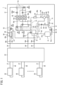
- FIG. 1 is a pattern view depicting a refrigerant circuit of a refrigeration apparatus according to the first embodiment of the present disclosure.
- a refrigeration apparatus 1 includes a refrigerant circuit configured to execute vapor compression refrigeration cycle operation.
- the refrigeration apparatus 1 according to the present embodiment is configured as an air conditioner.
- the air conditioner 1 includes an outdoor unit (heat source unit) 31, a plurality of indoor units (utilization units) 32, and a flow path switching device 33.
- the outdoor unit 31 and the flow path switching device 33, as well as the flow path switching device 33 and the indoor units 32 are respectively connected via connection pipes 34, 35, 36, 37, and 38.
- the air conditioner 1 according to the present embodiment is of a so-called freely cooling and heating type configured to allow each of the indoor units 32 to individually execute cooling operation or heating operation.
- the refrigeration apparatus 1 is not limited to the air conditioner but may alternatively be configured as a refrigerator, a freezer, a hot-water supplier, or the like.
- the outdoor unit 31 includes a refrigerant circuit 30.
- the refrigerant circuit 30 is connected to a refrigerant circuit in the flow path switching device 33 via a liquid connection pipe 34, a sucked gas connection pipe 35, and a high and low-pressure gas connection pipe 36.
- the refrigerant circuit in the flow path switching device 33 is connected to a refrigerant circuit in each of the indoor units 32 via the connection pipes 37 and 38.
- the refrigerant circuit 30 includes a first shutoff valve 39a, a second shutoff valve 39b, a third shutoff valve 39c, a compressor 40, an accumulator 41, a plurality of flow path switching valves (switching mechanisms) 42 (42a, 42b, and 42c), an outdoor heat exchanger 43, a plurality of expansion valves 44 (44a, 44b, 44c, and 44d), a subcooler 45, an oil separator 46, and the like. These components are connected via refrigerant pipes to constitute the refrigerant circuit.
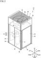
- the outdoor unit 31 is provided therein with a fan 62 (see FIG. 2 ), a controller 61a (see FIG. 3 ), and the like.
- the first shutoff valve 39a has a first end connected to the sucked gas connection pipe 35.
- the first shutoff valve 39a has a second end connected to a refrigerant pipe extending to the accumulator 41.
- the second shutoff valve 39b has a first end connected to the high and low-pressure gas connection pipe 36.
- the second shutoff valve 39b has a second end connected to a refrigerant pipe extending to the flow path switching valve 42b.
- the third shutoff valve 39c has a first end connected to the liquid connection pipe 34.
- the third shutoff valve 39c has a second end connected to a refrigerant pipe extending to the subcooler 45.
- the compressor 40 has a hermetic structure incorporating a compressor motor, and is of a positive-displacement type such as a scroll type or a rotary type.
- the compressor 40 compresses a low-pressure refrigerant sucked from a suction pipe 47 and then discharges the compressed refrigerant from a discharge pipe 48.
- the compressor 40 contains refrigerating machine oil. This refrigerating machine oil occasionally circulates in the refrigerant circuit 30 along with a refrigerant.
- the compressor 40 is a kind of container.
- the oil separator 46 is a container used for separation of the refrigerating machine oil from the refrigerant discharged from the compressor 40.
- the refrigerating machine oil thus separated is returned to the compressor 40 via an oil return tube 46a.
- the accumulator 41 is a container temporarily storing the low-pressure refrigerant to be sucked into the compressor 40 and used for separation between a gas refrigerant and a liquid refrigerant.
- the accumulator 41 has an inflow port 41b connected to a refrigerant pipe extending from the first shutoff valve 39a.
- the accumulator 41 has an outflow port 41a connected to the suction pipe 47.
- the accumulator 41 is connected with a first end of an oil return tube 50.
- the oil return tube 50 has a second end connected to the suction pipe 47.
- the oil return tube 50 is provided to return the refrigerating machine oil from the accumulator 41 to the compressor 40.
- the oil return tube 50 is provided with a first on-off valve 51.
- the first on-off valve 51 is constituted by an electromagnetic valve. When the first on-off valve 51 is opened, the refrigerating machine oil in the accumulator 41 passes through the oil return tube 50 and is sucked into the compressor 40 along with the refrigerant flowing in the suction pipe 47.
- the flow path switching valves 42 are each configured as a four-way switching valve. Each of the flow path switching valves 42 switches a refrigerant flow in accordance with an operation condition of the air conditioner 1. Each of the flow path switching valves 42 has a refrigerant inflow port connected with a refrigerant pipe extending from the oil separator 46.
- Each of the flow path switching valves 42 is configured to shut off a refrigerant flow in a single refrigerant flow path during operation, and actually functions as a three-way valve.
- the plurality of flow path switching valves 42 will hereinafter also be referred to as a first flow path switching valve 42a, a second flow path switching valve 42b, and a third flow path switching valve 42c.
- expansion valves 44 include a motor valve having an adjustable opening degree. Each of the expansion valves 44 has the opening degree adjusted in accordance with the operation condition, and decompresses the refrigerant passing therethrough in accordance with the opening degree.
- the plurality of expansion valves 44 will hereinafter also be referred to as a first expansion valve 44a, a second expansion valve 44b, a third expansion valve 44c, and a fourth expansion valve 44d.
- the outdoor heat exchanger 43 is of a cross-fin type or a microchannel type.
- the outdoor heat exchanger 43 includes a first heat exchange unit 43a, a second heat exchange unit 43b, a third heat exchange unit 43c, and a fourth heat exchange unit 43d.
- the first heat exchange unit 43a has a gas side end connected to a refrigerant pipe extending to the third flow path switching valve 42c.
- the first heat exchange unit 43a has a liquid side end connected to a refrigerant pipe extending to the first expansion valve 44a.
- the second heat exchange unit 43b has a gas side end connected to a refrigerant pipe extending to the first flow path switching valve 42a.
- the second heat exchange unit 43b has a liquid side end connected to a refrigerant pipe extending to the second expansion valve 44b.
- the third heat exchange unit 43c and the fourth heat exchange unit 43d each have a gas side end connected to a refrigerant pipe extending from the oil separator 46 and branched.
- the third heat exchange unit 43c and the fourth heat exchange unit 43d each have a liquid side end connected to a refrigerant pipe extending to the third expansion valve 44c.
- the subcooler 45 includes a first heat transfer tube 45a and a second heat transfer tube 45b.
- the first heat transfer tube 45a has a first end connected to a refrigerant pipe extending to the first to third expansion valves 44a, 44b, and 44c.
- the first heat transfer tube 45a has a second end connected to a refrigerant pipe extending to the third shutoff valve 39c.
- the second heat transfer tube 45b has a first end connected to a first branching tube 53 branching from a refrigerant pipe provided between the first heat transfer tube 45a and the first to third expansion valves 44a, 44b, and 44c.
- the first branching tube 53 is provided with the fourth expansion valve 44d.
- the second heat transfer tube 45b has a second end connected to a first end of an injection pipe 55.
- the injection pipe 55 has a second end connected to an intermediate port of the compressor 40.
- the injection pipe 55 is connected with a first end of a second branching tube 56.
- the second branching tube 56 has a second end (outlet end) connected to the suction pipe 47.
- the second branching tube 56 is provided with a second on-off valve 57 and a check valve 58.
- the second on-off valve 57 is constituted by an electromagnetic valve.
- the subcooler 45 causes heat exchange between the refrigerant flowing from the compressor 40, passing through the outdoor heat exchanger 43 and the expansion valves 44, and flowing in the first heat transfer tube 45a, and the refrigerant decompressed by the expansion valve 44d and flowing in the second heat transfer tube 45b, to subcool the refrigerant flowing in the first heat transfer tube 45a.
- the refrigerant flowing in the second heat transfer tube 45b passes through the injection pipe 55 and is sucked into the intermediate port of the compressor 40.
- the second on-off valve 57 is opened, the refrigerant flowing in the injection pipe 55 branches into the second branching tube 56 to flow therein and passes through the suction pipe 47 to be sucked into the compressor 40.
- FIG. 2 is a perspective view of the refrigeration apparatus.
- FIG. 3 is a plan view depicting the interior of the refrigeration apparatus.
- the following description refers to a transverse direction, an anteroposterior direction, and a vertical direction according to arrows X, Y, and Z indicated in FIG. 2 and FIG. 3 .
- the arrow X in FIG. 2 and FIG. 3 indicates a first direction corresponding to the transverse direction
- the arrow Y indicates a second direction corresponding to the anteroposterior direction
- the arrow Z indicates a third direction corresponding to the vertical direction. Note that these directions are described exemplarily without limiting the present disclosure.
- the first direction X may correspond to the anteroposterior direction
- the second direction Y may correspond to the transverse direction.
- the outdoor unit 31 includes a casing 60 accommodating components such as the compressor 40, the accumulator 41, the outdoor heat exchanger 43, and the oil separator 46 constituting the refrigerant circuit, an electric component unit 61, the fan 62, and the like.
- the fan 62 is provided at the top of the casing 60.
- the casing 60 has a substantially rectangular parallelepiped shape.
- the casing 60 has a bottom plate 63, a support 64, a top panel 65, a front panel 66, and the like.
- the bottom plate 63 has a quadrilateral shape in a top view.
- the support 64 is constituted by a long member having a substantially L sectional shape and elongating in the vertical direction, and is attached to each of four corners of the bottom plate 63.
- the top panel 65 has a quadrilateral shape substantially identically to the bottom plate 63, and is disposed above and apart from the bottom plate 63.
- the top panel 65 has four corners attached to upper ends of the supports 64.
- the top panel 65 is provided with a vent hole having a substantially quadrilateral shape and provided with a grill 65a preventing entry of foreign matters.
- the casing 60 has a front surface provided with an opening 60a for maintenance.
- the opening 60a is closed by the front panel (front side plate) 66. Detaching the front panel 66 from the casing 60 enables maintenance, replacement, and the like of the components in the casing 60 via the opening 60a.
- the bottom plate 63 of the casing 60 is provided thereon with components such as the compressor 40, the accumulator 41, the outdoor heat exchanger 43, and the oil separator 46.
- the outdoor heat exchanger 43 is disposed to correspond to (face) three side surfaces of the casing 60.
- the outdoor heat exchanger 43 has a U shape in a top view to extend along a left side surface, a right side surface, and a rear side surface of the casing 60.
- the outdoor heat exchanger 43 has a first end part provided with a gas header 43e, and a second end part provided with a liquid header 43f.
- the left side surface, the right side surface, and the rear side surface of the casing 60 are each provided with an intake port 60b for entry of outdoor air.
- the outdoor unit 31 is configured to, when the fan 62 is driven, receive air via the intake port 60b of the casing 60, cause heat exchange between the received air and the outdoor heat exchanger 43, and then send out air upward from the top of the casing 60.
- the compressor 40 is disposed at a substantially center in the transverse direction X in the vicinity of the front surface of the casing 60.
- the electric component unit 61 is disposed in the vicinity of the front surface of the casing 60 and adjacent to a right side of the compressor 40.
- the compressor 40 is provided therebehind with the accumulator 41.
- the accumulator 41 has a left side provided with the oil separator 46.
- the electric component unit 61 includes the controller 61a configured to control behavior of the compressor 40, the valves 42 and 44, the fan 62, and the like.
- FIG. 4 is a perspective view of a refrigerant flow path module.
- FIG. 5 is a schematic side view of the refrigerant flow path module.
- the outdoor unit is provided with a refrigerant flow path module 10.
- the refrigerant flow path module 10 is a module (unit) constituting part of flow paths of refrigerant pipes connecting components such as the compressor 40, the accumulator 41, the flow path switching valves 42, the outdoor heat exchanger 43, the expansion valves 44, and the oil separator 46.
- the refrigerant flow path module 10 according to the present embodiment constitutes refrigerant flow paths disposed in frames F1 and frames F2 each indicated by a two-dot chain line in FIG. 1 .
- the refrigerant flow path module 10 includes an upper refrigerant flow path module 10A and a lower refrigerant flow path module 10B.
- the upper refrigerant flow path module 10A constitutes the refrigerant flow paths in the frames F1 in FIG. 1 .
- the lower refrigerant flow path module 10B constitutes the refrigerant flow paths in the frames F2 in FIG. 1 .
- the upper refrigerant flow path module 10A and the lower refrigerant flow path module 10B each include a module body 11 having an internal flow path, and a joint tube (refrigerant tube) 12 attached to the module body 11 and communicating with the flow path in the module body 11.
- the module body 11 of the upper refrigerant flow path module 10A may be called a first module body 11 and the module body 11 of the lower refrigerant flow path module 10B may be called a second module body.
- the module body 11 is constituted by a plurality of stacked plates, and has a plate or block shape.
- the module body 11 has an upper surface and a lower surface each having a rectangular shape in a planar view.
- the module body 11 is disposed such that the upper surface and the lower surface are directed in a horizontal direction.
- the module body 11 has a thickness (vertical length) less than lengths of a long side and a short side of the rectangular shape.
- the module body 11 thus has a flat shape and is disposed in parallel with the horizontal direction.
- the module body 11 may not be disposed exactly in parallel with the horizontal direction, and may exemplarily be slanted by at most ⁇ 10° from the horizontal direction.
- the upper refrigerant flow path module 10A and the lower refrigerant flow path module 10B are disposed in parallel with each other.
- the upper refrigerant flow path module 10A and the lower refrigerant flow path module 10B are disposed to be overlapped with each other in a top view.
- the upper refrigerant flow path module 10A is larger in area than the lower refrigerant flow path module 10B in a top view.
- the lower refrigerant flow path module 10B is disposed in a vertical projection area of the upper refrigerant flow path module 10A.
- the joint tube 12 is a cylinder attached to each of the upper and lower surfaces of the module body 11.
- the joint tubes 12 are disposed to have axes vertical to the upper and lower surfaces of the module body 11.
- the joint tube 12 is connected with a refrigerant pipe constituting a refrigerant circuit.
- the refrigerant flow path module 10 is disposed on the left side (a first side in the first direction X) of the compressor 40 and the accumulator 41.
- the refrigerant flow path module 10 is disposed ahead (on a first side in the second direction Y) of the oil separator 46.
- the refrigerant flow path module 10 according to the present embodiment, specifically the upper refrigerant flow path module 10A, is supported by a refrigerant pipe via components constituting the refrigerant circuit fixed onto the bottom plate 63 of the casing 60.
- the lower refrigerant flow path module 10B is substantially supported by the upper refrigerant flow path module 10A via a refrigerant pipe and the components constituting the refrigerant circuit.
- the upper refrigerant flow path module 10A will be specifically described in terms of its support structure.
- the upper refrigerant flow path module 10A has a lower end connected with a refrigerant pipe 21 connected to the refrigerant outflow port 41a of the accumulator 41 and a refrigerant pipe 22 connected to the refrigerant inflow port 41b.
- the refrigerant pipe 21 constitutes part of a flow path (second flow path) for a refrigerant flow between a suction side of the compressor 40 and the flow path switching valves 42a to 42c.
- the refrigerant pipe 22 also constitutes part of the flow path (second flow path) for the refrigerant flow between the suction side of the compressor 40 and the flow path switching valves 42a to 42c.
- the accumulator 41 is attached and fixed to a fixture 67 provided on the bottom plate 63 of the casing 60 of the outdoor unit 31.
- the refrigerant outflow port 41a is provided at the bottom of the accumulator 41.
- the refrigerant pipe 21 is bent and extends upward from a connecting portion to the refrigerant outflow port 41a, and has an upper end connected to the joint tube 12 provided on the lower surface of the module body 11 of the upper refrigerant flow path module 10A.
- the refrigerant inflow port 41b is provided at the top of the accumulator 41.
- the refrigerant pipe 22 is bent vertically and extends toward the upper refrigerant flow path module 10A from a connecting portion to the refrigerant inflow port 41b, and is connected to the joint tube 12 provided on the lower surface of the module body (first module body) 11 of the upper refrigerant flow path module 10 A.
- the lower end of the upper refrigerant flow path module 10A is also connected with a refrigerant pipe 23 connected to the first shutoff valve (gas shutoff valve) 39a serving as an inlet for a gas refrigerant from the flow path switching device 33 (see FIG. 1 ).
- the refrigerant pipe 23 constitutes part of a flow path (third flow path) for a refrigerant flow between the first shutoff valve 39a and the flow path switching valve 42b.
- the first shutoff valve 39a is attached and fixed to a fixture 68 provided on the bottom plate 63.
- the refrigerant pipe 23 is bent and extends upward from the first shutoff valve 39a, and has an upper end connected to the joint tube 12 provided on the lower surface of the module body 11 of the upper refrigerant flow path module 10A.
- the upper refrigerant flow path module 10A is supported by the refrigerant pipe 21, the refrigerant pipe 22, and the refrigerant pipe 23. Specifically, the upper refrigerant flow path module 10A is supported from below by the refrigerant pipe 21, the refrigerant pipe 22, and the refrigerant pipe 23. The upper refrigerant flow path module 10A is disposed above and apart from the bottom plate 63 of the casing 60.
- the refrigerant pipe 21, the refrigerant pipe 22, and the refrigerant pipe 23 are gas pipes for a gas refrigerant flow. The gas pipes are larger in pipe diameter and higher in strength than a liquid pipe for a liquid refrigerant flow.
- the upper refrigerant flow path module 10A is thus stably supported by these refrigerant pipes 21, 22, and 23.
- the refrigerant pipe 21 and the refrigerant pipe 22 are connected to the accumulator 41 fixed to the casing 60, whereas the refrigerant pipe 23 is connected to the first shutoff valve 39a fixed to the casing 60. Accordingly, the upper refrigerant flow path module 10A is more stably supported by the refrigerant pipes 21, 22, and 23 via the components 41 and 39a constituting the refrigerant circuit fixed to the casing 60.
- FIG. 6 is a bottom view of a schematic module body, indicating disposition of refrigerant pipes supporting the refrigerant flow path module.
- the three refrigerant pipes 21, 22, and 23 supporting the upper refrigerant flow path module 10A are connected at positions distributed on both sides of a center C1 in a longitudinal direction of the module body 11.
- the refrigerant pipe 22 and the refrigerant pipe 23 are disposed on a first side of the center C1 in the longitudinal direction
- the refrigerant pipe 21 is disposed on a second side of the center C1 in the longitudinal direction.
- the plurality of refrigerant pipes 21, 22, and 23 is accordingly distributed on both sides of the center C1 in the longitudinal direction of the module body 11.
- the plurality of refrigerant pipes 21, 22, and 23 is dispersed in the longitudinal direction of the module body 11.
- the plurality of refrigerant pipes 21, 22, and 23 can thus stably support the upper refrigerant flow path module 10A.
- the plurality of refrigerant pipes 21, 22, and 23 according to the present embodiment is clustered on a first side in a short direction of the module body 11.
- FIG. 7 is an enlarged front view of a connecting portion between the refrigerant flow path module and a refrigerant pipe.
- the joint tube 12 provided on the lower surface of the module body 11 of the upper refrigerant flow path module 10A has an upper end connected to the module body 11 and a lower end connected to the refrigerant pipe 21, 22, or 23.
- the refrigerant pipe 21, 22, or 23 connected to the joint tube 12 has an upper end part provided with a diameter expanded part D processed to be flared to have an increased diameter.
- the upper end part of the refrigerant pipe 21, 22, or 23 receives a lower end part of the joint tube 12 to be brazed together. Accordingly, connection between the joint tube 12 and the refrigerant pipe 21, 22, or 23 enables brazing from above to an upper end surface of the refrigerant pipe 21, 22, or 23 and facilitates manual brazing.
- the upper surface of the module body 11 of the upper refrigerant flow path module 10A is connected with a refrigerant pipe 24 connected to a refrigerant inflow port 40b of the compressor 40.
- the refrigerant pipe 24 constitutes part of the flow path (second flow path) for a refrigerant flow between the suction side of the compressor 40 and the flow path switching valves 42a to 42c.
- the refrigerant pipe 24 extends upward from a connecting portion to the refrigerant inflow port 40b of the compressor 40, is further bent to extend horizontally, is bent again to extend downward, and has a lower end connected to the joint tube 12 provided on the upper surface of the module body 11.
- the upper refrigerant flow path module 10A is supported also from above by the refrigerant pipe 24.
- the refrigerant pipe 24 is a gas pipe for a gas refrigerant flow, and is larger in diameter and higher in strength than a liquid pipe.
- the upper refrigerant flow path module 10A is thus stably supported by the refrigerant pipe 24.
- the compressor 40 is fixed via a fixture or the like provided on the bottom plate 63 of the casing. Accordingly, the upper refrigerant flow path module 10A is more stably supported by the refrigerant pipe 24 via the compressor 40 fixed to the bottom plate 63.
- the upper refrigerant flow path module 10A has an upper end connected with the flow path switching valve 42b.
- This flow path switching valve 42b includes a valve body B incorporating a valve disc, and a plurality of ports P each serving as a refrigerant outlet or inlet for the valve body B.
- the ports P project upward and downward from the valve body B. Among these ports, the port P projecting downward is connected directly to the joint tube 12 provided at the top of the upper refrigerant flow path module 10A.
- the lower refrigerant flow path module 10B is disposed below and apart from the upper refrigerant flow path module 10A.
- the lower refrigerant flow path module 10B is disposed above and apart from the bottom plate 63 of the casing 60.
- the upper refrigerant flow path module 10A and the lower refrigerant flow path module 10B interpose the flow path switching valves 42a and 42c.
- These flow path switching valves 42a and 42c each include a valve body B incorporating a valve disc, and a plurality of ports P each serving as a refrigerant outlet or inlet for the valve body B.
- the ports P project upward and downward from the valve body B.
- the port P projecting upward is connected directly to the joint tube 12 provided on the lower surface of the module body 11 of the upper refrigerant flow path module 10A.
- the port P projecting downward is connected directly to the joint tube 12 provided on the upper surface of the module body (second module body) 11 of the lower refrigerant flow path module 10B.
- the upper refrigerant flow path module 10A and the lower refrigerant flow path module 10B interpose a refrigerant pipe 25.
- the refrigerant pipe 25 constitutes part of a flow path (first flow path) for a refrigerant flow between a discharge side of the compressor 40 and the flow path switching valve 42b. More specifically, the refrigerant pipe 25 constitutes part of a flow path for a refrigerant flow between the flow path switching valve 42b and the oil separator 46.
- FIG. 1 the refrigerant pipe 25 constitutes part of a flow path (first flow path) for a refrigerant flow between a discharge side of the compressor 40 and the flow path switching valve 42b.
- the refrigerant pipe 25 constitutes part of a flow path for a refrigerant flow between the flow path switching valve 42b and the oil separator 46.
- this refrigerant pipe 25 extends linearly in the vertical direction, and has an upper end connected to the joint tube 12 provided on the lower surface of the module body 11 of the upper refrigerant flow path module 10A, and a lower end connected to the joint tube 12 provided on the upper surface of the module body 11 of the lower refrigerant flow path module 10B.
- the refrigerant pipe 25 thus connects the upper refrigerant flow path module 10A and the lower refrigerant flow path module 10B in a shortest distance.
- the lower refrigerant flow path module 10B is has a lower end connected with the plurality of expansion valves 44.
- the lower refrigerant flow path module 10B is connected with the upper refrigerant flow path module 10A by the flow path switching valves 42a and 42c and the refrigerant pipe 25, and is supported from above by the upper refrigerant flow path module 10A via these components.
- FIG. 8 is a bottom view of a schematic module body, indicating disposition of pipes supporting a refrigerant flow path module according to a modification example.
- the three refrigerant pipes 21, 22, and 23 supporting the upper refrigerant flow path module 10A may alternatively be disposed in the manner depicted in FIG. 8 instead of the manner depicted in FIG. 6 .
- the two refrigerant pipes 21 and 23 are connected at positions distributed on both sides of the center C1 in the longitudinal direction of the module body 11.
- the remaining single refrigerant pipe 22 is disposed on the center C1 in the longitudinal direction of the module body 11.
- the two refrigerant pipes 21 and 23 and the single refrigerant pipe 22 are distributed on both sides of a center C2 in the short direction of the module body 11.
- the plurality of refrigerant pipes 21, 22, and 23 is distributed on both sides of the center C2 in the short direction of the module body 11 as well as on both sides of the center C1 in the longitudinal direction. Furthermore, the plurality of refrigerant pipes 21, 22, and 23 is dispersed in the longitudinal direction of the module body 11. The plurality of refrigerant pipes 21, 22, and 23 can thus more stably support the upper refrigerant flow path module 10A.
- FIG. 9 is a bottom view of a schematic module body, indicating disposition of pipes supporting a refrigerant flow path module according to another modification example.
- the three refrigerant pipes supporting the upper refrigerant flow path module 10A may alternatively be disposed in the manner depicted in FIG. 9 instead of the manner depicted in FIG. 6 .
- the two refrigerant pipes 21 and 23 are connected at positions distributed on both sides of the center C1 in the longitudinal direction of the module body 11 and on both sides of the center C2 in the short direction.
- the remaining single refrigerant pipe 22 is disposed on the center C1 in the longitudinal direction of the module body 11 and the center C2 in the short direction.
- the plurality of refrigerant pipes 21, 22, and 23 is distributed on both sides of the center C2 in the short direction of the module body 11 as well as on both sides of the center C1 in the longitudinal direction. Furthermore, the plurality of refrigerant pipes 21, 22, and 23 is dispersed in the longitudinal direction and the short direction of the module body 11. The plurality of refrigerant pipes 21, 22, and 23 can thus more stably support the upper refrigerant flow path module 10A.
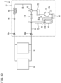
- FIG. 10 is a pattern view depicting a refrigerant circuit of a refrigeration apparatus according to the second embodiment.
- the refrigeration apparatus 1 is configured as the air conditioner of the so-called freely cooling and heating type, and includes the flow path switching device 33 disposed between the outdoor unit 31 and the indoor units 32.
- the present embodiment provides a refrigeration apparatus 1 including no such flow path switching device 33 and including an outdoor unit 31 and an indoor unit 32 connected directly via a connection pipe.
- FIG. 11 is a schematic side view of a refrigerant flow path module according to the second embodiment.
- the outdoor unit 31 includes a single refrigerant flow path module 10.
- This refrigerant flow path module 10 constitutes refrigerant flow paths in frames F3 in FIG. 10 .
- the refrigerant flow path module 10 is supported from below by a plurality of refrigerant pipes 21, 22, and 23.
- the refrigerant flow path module 10 according to the present embodiment has a lower end connected with the refrigerant pipe 21 connected to a refrigerant outflow port 41a of an accumulator 41 and the refrigerant pipe 22 connected to a refrigerant inflow port 41b.
- the lower end of the refrigerant flow path module 10 is also connected with the refrigerant pipe 23 connected to a shutoff valve 39d serving as an outlet or an inlet for a gas refrigerant from the indoor unit 32.
- the shutoff valve 39d is attached and fixed to a fixture 68 provided on a bottom plate 63 of a casing 60.
- the refrigerant pipe 23 is bent and extends upward from the shutoff valve 39d, and is connected to a joint tube 12 provided on a lower surface of a module body 11 of the refrigerant flow path module 10.
- the refrigerant flow path module 10 is thus disposed above the bottom plate 63 of the casing 60, and is supported from below by the refrigerant pipe 21, the refrigerant pipe 22, and the refrigerant pipe 23.
- the refrigerant pipe 21, the refrigerant pipe 22, and the refrigerant pipe 23 are gas pipes for a gas refrigerant flow.
- the gas pipes are larger in pipe diameter and higher in strength than a liquid pipe for a liquid refrigerant flow.
- the refrigerant flow path module 10 is thus stably supported by these refrigerant pipes 21, 22, and 23.
- the refrigerant pipe 21 and the refrigerant pipe 22 are connected to the accumulator 41 fixed to the casing 60, whereas the refrigerant pipe 23 is connected to the shutoff valve 39d fixed to the casing 60. Accordingly, the refrigerant flow path module 10 is more stably supported by the refrigerant pipes 21, 22, and 23 via the components 41 and 39d constituting the refrigerant circuit fixed to the casing 60.
- the module body 11 of the refrigerant flow path module 10 has an upper surface connected with a refrigerant pipe 24 connected to a refrigerant inflow port 40b of a compressor 40.
- the refrigerant pipe 24 extends upward from a connecting portion to the refrigerant inflow port 40b of the compressor 40, is further bent to extend horizontally, is bent again to extend downward, and has a lower end connected to a joint tube 12 provided on the upper surface of the module body 11.
- the refrigerant flow path module 10 is supported also from above by the refrigerant pipe 24.
- the refrigerant pipe 24 is a gas pipe for a gas refrigerant flow, and is larger in diameter and higher in strength than a liquid pipe.
- the refrigerant flow path module 10 is thus stably supported by the refrigerant pipe 24.
- the compressor 40 is fixed via a fixture or the like provided on the bottom plate 63 of the casing 60. Accordingly, the refrigerant flow path module 10 is more stably supported by the refrigerant pipe 24 via the compressor 40 fixed to the bottom plate 63.
- the refrigerant flow path module 10 has an upper end connected with a flow path switching valve 42.
- the flow path switching valve 42 includes a valve body B incorporating a valve disc, and a plurality of ports P each serving as a refrigerant outlet or inlet for the valve body B.
- the ports P project upward and downward from the valve body B. Among these ports, the port P projecting downward is connected directly to the joint tube 12 provided on the upper surface of the module body 11 of the refrigerant flow path module 10.
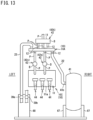
- FIG. 12 is a schematic side view of a refrigerant flow path module according to the third embodiment.
- FIG. 13 is a schematic front view of the refrigerant flow path module.
- the present embodiment provides a refrigerant flow path module 10 including an upper refrigerant flow path module 10A and a lower refrigerant flow path module 10C.
- the lower refrigerant flow path module 10C according to the present embodiment includes a module body (second module body) 11 directed differently from the direction according to the first embodiment, specifically in the vertical direction.
- the second module body 11 is constituted by a plurality of stacked plates, and has a plate or block shape.
- the second module body 11 according to the present embodiment includes the plurality of plates stacked in the horizontal direction (anteroposterior direction).
- the second module body 11 includes a front surface (first side surface) 11a and a rear surface (second side surface) 11b each having a rectangular shape in a front view (or a rear view).
- the front surface 11a and the rear surface 11b are facing opposite to each other.
- the front surface 11a and the rear surface 11b of the second module body 11 are directed substantially in the vertical direction.
- the front surface 11a and the rear surface 11b of the second module body 11 may not be directed exactly in a normal direction, and may exemplarily be slanted by at most ⁇ 10°from the normal direction.
- the front surface 11a and the rear surface 11b of the second module body 11 are directed substantially in the transverse direction.
- the front surface 11a and the rear surface 11b of the second module body 11 may not be directed exactly in the transverse direction, and may exemplarily be slanted by at most ⁇ 45° from the transverse direction.
- the second module body 11 disposed in such a range facilitates maintenance, replacement, and the like of components such as valves 42a, 42c, and 44 attached to the front surface 11a as to be described later.
- a length between the front surface 11a and the rear surface 11b of the second module body 11, in other words, a thickness of the second module body 11, is less than a vertical length of the second module body 11, in other words, a height of the second module body 11.
- the thickness of the second module body 11 is less than a transverse length of the second module body 11.
- the lower refrigerant flow path module 10C is disposed below and apart from the upper refrigerant flow path module 10A.
- the lower refrigerant flow path module 10C is positioned to be at least partially overlapped with the upper refrigerant flow path module 10A in a planar view.
- the lower refrigerant flow path module 10C is shifted to one anteroposterior side (to a rear side) of the upper refrigerant flow path module 10A.
- the lower refrigerant flow path module 10C may be supported by a support member fixed onto a bottom plate 63 of a casing 60, and may be supported substantially by the upper refrigerant flow path module 10A via a refrigerant pipe and a component constituting a refrigerant circuit.
- the upper refrigerant flow path module 10A is thus provided therebelow with a vertically wide space S. Particularly below the upper refrigerant flow path module 10A and ahead of the lower refrigerant flow path module 10C, the space S expands widely and continuously to an upper end and a lower end of the lower refrigerant flow path module 10C.
- This space S is provided with the flow path switching valves 42a and 42c, the expansion valve 44, a different refrigerant pipe, and the like.
- the flow path switching valve 42a and 42c each have an upper port P connected directly to a joint tube 12 provided on a lower surface of the first module body 11 of the upper refrigerant flow path module 10A, and a lower port P connected to a joint tube 12 provided on the front surface 11a of the second module body 11 of the lower refrigerant flow path module 10C directly or via a different pipe (e.g. a pipe bent at a right angle).
- the expansion valve 44 is connected directly to a joint tube 12 provided on the front surface 11a of the second module body 11 of the lower refrigerant flow path module 10C.
- the front surface (first side surface) 11a of the second module body 11 faces a front panel 66 and a maintenance opening 60a of the casing 60.
- the flow path switching valves 42a and 42c and the expansion valve 44 are attached to the front surface 11a of the second module body 11, and maintenance and replacement of components can thus be easily executed via the maintenance opening 60a opened by detaching the front panel 66.
- the lower refrigerant flow path module 10C may alternatively be shifted to a front side of the upper refrigerant flow path module 10A.
- the space S widened vertically is provided behind the lower refrigerant flow path module 10C and below the upper refrigerant flow path module 10A.
- the lower refrigerant flow path module 10C may alternatively be not overlapped with the upper refrigerant module 10A in a planar view.
- the lower refrigerant flow path module 10C may be supported by a support member extending from a fixture 68.
- a refrigerant pipe 23 connected to a first shutoff valve (gas shutoff valve) 39a is connected to an upper end of the upper refrigerant flow path module 10A.
- the refrigerant pipe 23 is bent and extends upward from the first shutoff valve 39a, and has an upper end connected to a joint tube 12 provided on an upper surface of the first module body 11 of the upper refrigerant flow path module 10A.
- a refrigerant pipe 22 connected to a refrigerant inflow port 41b of an accumulator 41 is connected to a lower end of the upper refrigerant flow path module 10A.
- the refrigerant pipe 22 is connected to a joint tube 12 provided on the lower surface of the first module body 11 of the upper refrigerant flow path module 10A.
- the upper refrigerant flow path module 10A is supported from below by the refrigerant pipe 22 and is supported from above by the refrigerant pipe 23.
- the refrigerant pipe 22 and the refrigerant pipe 23 are gas pipes for a gas refrigerant flow, and are larger in pipe diameter and higher in strength than a liquid pipe for a liquid refrigerant flow.
- the upper refrigerant flow path module 10A is thus stably supported by these refrigerant pipes 22 and 23.
- the refrigerant pipe 22 is connected to the accumulator 41 fixed to the casing 60 and the refrigerant pipe 23 is connected to the first shutoff valve 39a fixed to the casing 60.
- the upper refrigerant flow path module 10A is more stably supported by the refrigerant pipes 22 and 23 via the components 41 and 39a constituting the refrigerant circuit fixed to the casing 60.
- the upper refrigerant flow path module 10A may alternatively be supported by a different refrigerant pipe (e.g. the refrigerant pipe 21, 24, or 25 according to the first embodiment).
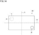
- FIG. 14 is a bottom view of a schematic module body, indicating disposition of refrigerant pipes supporting the refrigerant flow path module.
- the two refrigerant pipes 22 and 23 supporting the upper refrigerant flow path module 10A are connected at positions distributed on both sides of a center C1 in the longitudinal direction of the module body 11.
- the refrigerant pipe 22 is disposed on a first side of the center C1 in the longitudinal direction
- the refrigerant pipe 23 is disposed on a second side of the center C1 in the longitudinal direction.
- the plurality of refrigerant pipes 22 and 23 is accordingly distributed on both sides of the center C1 in the longitudinal direction of the module body 11.
- the plurality of refrigerant pipes 22 and 23 is dispersed in the longitudinal direction of the module body 11.
- the plurality of refrigerant pipes 22 and 23 can thus stably support the upper refrigerant flow path module 10A in a well-balanced manner.
- the two refrigerant pipes 22 and 23 are connected at positions distributed on both sides of a center C2 in the short direction of the module body 11. Specifically, the refrigerant pipe 22 is disposed on a first side of the center C2 in the short direction, whereas the refrigerant pipe 23 is disposed on a second side of the center C2 in the short direction.
- the plurality of refrigerant pipes 22 and 23 is accordingly distributed and dispersed on both sides in the longitudinal direction as well as in the short direction of the module body 11. The two refrigerant pipes 22 and 23 can thus stably support the upper refrigerant flow path module 10A in a well-balanced manner.
- the upper refrigerant flow path module 10A is supported from below by the three refrigerant pipes 21 to 23, and may alternatively be supported from below by two refrigerant pipes.
- the two refrigerant pipes are preferably distributed on both sides in the longitudinal direction of the module body 11 of the upper refrigerant flow path module 10A.
- the upper refrigerant flow path module 10A may still alternatively be supported from below by four or more refrigerant pipes.
- the lower refrigerant flow path module 10B instead of the upper refrigerant flow path module 10A may be supported from below by two or more refrigerant pipes.
- the heat exchanger 43 includes the four heat exchange units 43a to 43d.
- the heat exchanger 43 may alternatively include two heat exchange units.
- any one of the flow path switching valves 42a and 42c can be excluded and any one of the expansion valves 44a and 44b can be excluded.
- the flow path switching valve 42b provided at the top of the upper refrigerant flow path module 10A may exemplarily be disposed between the upper refrigerant flow path module 10A and the lower refrigerant flow path module 10B or 10C.
- the heat source unit (outdoor unit) 31 includes the compressor 40, the refrigerant pipes 21 to 25 for a flow of a gas refrigerant having been discharged from the compressor 40 and a flow of a gas refrigerant to be sucked into the compressor 40, the refrigerant flow path module 10 connected to the refrigerant pipes 21 to 25, and the casing 60 accommodating the compressor 40, the refrigerant pipes 21 to 25, and the refrigerant flow path module 10.
- the refrigerant flow path module 10 includes the module body 11 having the upper surface and the lower surface, having the vertical length less than the horizontal length, and provided therein with the refrigerant flow path.
- the refrigerant flow path module 10 is disposed above and apart from the bottom part (bottom plate) 63 of the casing 60.
- the refrigerant pipes 21 to 25 include a first pipe and a second pipe (any two of the refrigerant pipes 21 to 23 according to the above embodiments) communicating with the flow path in the module body 11 and supporting the refrigerant flow path module 10.
- the refrigerant flow path module 10 thus configured is disposed above the bottom plate (bottom part) 63 of the casing 60 and is enhanced in disposition flexibility in the casing 60. Accordingly, the refrigerant pipe connecting a component such as the compressor 40 and the refrigerant flow path module 10 can be shortened in comparison to the case where the refrigerant flow path module 10 is disposed in the bottom part of the casing 60.
- the refrigerant flow path module 10 is supported by the first and second pipes 21 22, or 23 for a gas refrigerant flow, so as to simplify a structure for disposition of the refrigerant flow path module 10 above the bottom part 63
- the first and second pipes 21, 22, or 23 according to the first or second embodiment support the refrigerant flow path module 10 from below.
- the refrigerant flow path module 10 can thus be stably supported from below.
- the module body 11 is elongated in a horizontal predetermined direction.
- the connecting portions of the first pipe and the second pipe (e.g. any of the refrigerant pipes 21 to 23) to the refrigerant flow path module 10 are distributed on both sides of the center C1 in the longitudinal direction of the module body 11. This achieves well-balanced support of the refrigerant flow path module 10 by the first and second pipes 21 and 23.
- the heat source unit 31 further includes the switching mechanism (flow path switching valve) 42 configured to switch a flow direction of a gas refrigerant, and the gas shutoff valve 39a or 39d constituting the outlet or the inlet of the gas refrigerant in the heat source unit 31.
- the first pipe and the second pipe (any two of the refrigerant pipes 21 to 23 according to the above embodiments) each constitute part of the first flow path for a refrigerant flow between the discharge side of the compressor 40 and the switching mechanism 42, part of the second flow path for a refrigerant flow between the suction side of the compressor 40 and the switching mechanism 42, or part of the third flow path for a refrigerant flow between the gas shutoff valve 39a and the switching mechanism 42.
- the first pipe or the second pipe corresponds to the refrigerant pipe 23 constituting part of the third flow path and connecting the gas shutoff valve 39a or 39d fixed to the casing 60 and the refrigerant flow path module 10.
- Such a configuration achieves stable support of the refrigerant flow path module 10 by the gas shutoff valve 39a fixed to the casing 60 and the refrigerant pipe 23.
- the above embodiments further provide the accumulator 41 provided on the second flow path for a refrigerant flow between the suction side of the compressor 40 and the switching mechanism 42 and fixed to the casing 60.
- the first pipe or the second pipe corresponds to the refrigerant pipe connecting the accumulator 41 and the refrigerant flow path module 10.
- Such a configuration achieves stable support of the refrigerant flow path module 10 by the accumulator 41 fixed to the casing 60 and the first or second pipe.
- the switching mechanism 42 includes the ports P each for a refrigerant inflow or outflow, and the ports P are connected directly to the refrigerant flow path module 10. This enables reduction in amount of refrigerant pipes in the heat source unit 31.
- the refrigerant flow path module 10 includes the joint tubes 12 each having the upper end connected to the lower surface of the module body 11 and the lower end connected to the first pipe (any one of the refrigerant pipes 21 to 23) or the second pipe (any one of the refrigerant pipes 21 to 23).
- the first or second pipe 21, 22, or 23 has the upper end provided with the diameter expanded part D having an expanded inner diameter, and first and second joint tubes 12 are each inserted into the diameter expanded part D of the first or second pipe 21, 22, or 23. This facilitates manual brazing of the first or second pipe 21, 22, or 23 to one of the joint tubes 12 of the refrigerant flow path module 10.
- the refrigerant pipes 21 to 25 further include the third pipe (any one of the refrigerant pipes 21 to 23 according to the above embodiments) communicating with the flow path in the module body 11 and supporting the refrigerant flow path module 10 from below, and the connecting portions of the first to third pipes 21 to 23 to the refrigerant flow path module 10 are dispersed in the longitudinal direction of the module body 11.
- This configuration achieves more stable support of the refrigerant flow path module 10 by the three refrigerant pipes, namely, the first to third pipes 21 to 23, and achieves well-balanced support of the refrigerant flow path module 10 by the first to third pipes 21 to 23 in the longitudinal direction of the module body 11.
- the refrigerant pipes 21 to 25 according to the first or second embodiment further includes a fourth pipe 24 communicating with the flow path in the module body 11 and supporting the refrigerant flow path module 10 from above.
- a fourth pipe 24 communicating with the flow path in the module body 11 and supporting the refrigerant flow path module 10 from above.
- the refrigerant flow path module 10 includes the first refrigerant flow path module (e.g. the upper refrigerant flow path module 10A) including the module body 11 and supported by the first pipe and second pipe, and the second refrigerant flow path module (e.g. the lower refrigerant flow path module 10B or 10C) disposed vertically apart from the first refrigerant flow path module and including the second module body 11 provided therein with the refrigerant flow path.
- the first refrigerant flow path module e.g. the upper refrigerant flow path module 10A
- the second refrigerant flow path module e.g. the lower refrigerant flow path module 10B or 10C
- the refrigerant flow path module needs to be large in order to avoid interference or the like between the refrigerant pipes or the refrigerant flow paths. This increases a portion provided with no flow path and a portion connected with no refrigerant pipe. This leads to difficulty in efficient connection of the plurality of refrigerant pipes and provision of the flow paths to the refrigerant flow path module.
- the refrigerant flow path module increased in size leads to increase in installation space (particularly an installation space in the horizontal direction) in the casing 60.
- the refrigerant flow path module 10 is constituted by the two modules, namely, the first refrigerant flow path module 10A and the second refrigerant flow path module 10B or 10C, so as to achieve efficient provision of the flow paths in the respective refrigerant flow path modules 10A and 10B or 10C as well as entire size reduction of the refrigerant flow path module 10.
- the installation space in the horizontal direction can be decreased when the two refrigerant flow path modules 10A and 10B or 10C are disposed vertically apart from each other and are overlapped with each other in a top view.
- the refrigerant pipes according to the first embodiment include a fifth pipe 25 extending vertically between the first refrigerant flow path module 10A and the second refrigerant flow path module 10B, and having an upper end connected to one of the first refrigerant flow path module 10A and the second refrigerant flow path module 10B and a lower end connected to the remaining one of the first refrigerant flow path module 10A and the second refrigerant flow path module 10B.
- This configuration enables connection between the first refrigerant flow path module 10A and the second refrigerant flow path module 10B by the fifth pipe 25 in a shortest distance.
- the first embodiment provides the switching mechanisms 42a and 42c each configured to switch a flow direction of a gas refrigerant, and the switching mechanisms 42a and 42c are disposed between the first refrigerant flow path module 10A and the second refrigerant flow path module 10B.
- Such a configuration enables effective use of the space between the first refrigerant flow path module 10A and the second refrigerant flow path module 10B.
- the second module body 11 includes the first side surface (e.g. the front surface) 11a and the second side surface (e.g. the rear surface) 11b directed in the vertical direction and facing opposite to each other, and the length between the first side surface 11a and the second side surface 11b is less than the vertical length of the second module body 11.
- the vertically wide space S can be secured above or below (adjacent to the second refrigerant flow path module 10C) the first refrigerant flow path module 10A even when the second refrigerant flow path module 10C is disposed vertically apart from the first refrigerant flow path module 10A, so as to enhance disposition flexibility of components such as refrigerant pipes and valves connected respectively to the refrigerant flow path modules 10A and 10C.
- the number of the plates constituting the module body of the refrigerant flow path module should not be particularly limited, and has only to be two or more.
- a refrigerant pipe supporting the refrigerant flow path module from below can be a refrigerant pipe provided for a gas refrigerant flow and extending from the oil separator 46, or a refrigerant pipe provided for a gas refrigerant flow and extending from the heat exchanger 43.
Landscapes
- Engineering & Computer Science (AREA)
- Physics & Mathematics (AREA)
- Mechanical Engineering (AREA)
- Thermal Sciences (AREA)
- General Engineering & Computer Science (AREA)
- Fluid Mechanics (AREA)
- Chemical & Material Sciences (AREA)
- Analytical Chemistry (AREA)
- Power Engineering (AREA)
- Other Air-Conditioning Systems (AREA)
Abstract
Description
- The present disclosure relates to a heat source unit.
- A refrigeration apparatus including a refrigerant circuit configured to execute vapor compression refrigeration cycle operation has been known to collectively include, in a single unit, a plurality of refrigerant pipes for refrigerant flows, to achieve reduction in size of the refrigerant circuit. For example,
PATENT LITERATURE 1 discloses a refrigerant pipe unit provided to a heat source unit of a refrigeration apparatus. This refrigerant pipe unit is constituted by a pair of plate-shaped members stacked to each other and is disposed with plate surfaces of these plate-shaped members directed vertically. The pair of plate-shaped members have stacking surfaces provided with a plurality of grooves for provision of refrigerant passages, and the upper plate-shaped member has an upper surface provided with communication holes communicating with the refrigerant passages. The upper surface of the upper plate-shaped member is provided with functional blocks such as a compressor and a switching valve, and the functional blocks are connected to the refrigerant pipe unit via the communication holes. - PATENT LITERATURE 1:
Japanese Laid-Open Patent Publication No. 2010-156528 - The refrigerant pipe unit according to PATENT
LITERATURE 1 has an upper surface provided with the compressor, and is thus disposed limitedly at a lower position in the heat source unit, such as on a bottom part of a casing of the heat source unit. Meanwhile, the refrigerant circuit in the heat source unit is provided with relatively large components such as an accumulator and an oil separator in addition to the compressor, and an inflow port or an outflow port for a refrigerant is typically provided at the top of each of these components. Accordingly, the refrigerant pipe unit disposed at a lower position in the heat source unit leads to increase in length of a refrigerant pipe connecting the inflow port or the outflow port of each component like the compressor and the refrigerant pipe unit, and leads to increase in amount of used refrigerant pipes. - It is an object of the present disclosure to provide a heat source unit achieving reduction in amount of used refrigerant pipes.
-
- (1) A heat source unit according to the present disclosure includes: a compressor; refrigerant pipes for a flow of a gas refrigerant having been discharged from the compressor and a flow of a gas refrigerant to be sucked into the compressor; a refrigerant flow path module connected to the refrigerant pipes; and a casing accommodating the compressor, the refrigerant pipes, and the refrigerant flow path module, in which the refrigerant flow path module includes a module body having an upper surface and a lower surface, having a vertical length less than a horizontal length, and provided therein with a flow path for a refrigerant, the refrigerant flow path module is disposed above and apart from a bottom part of the casing, and the refrigerant pipes include a first pipe and a second pipe each communicating with the flow path in the module body and supporting the refrigerant flow path module.
According to the above configuration, the refrigerant flow path module is disposed above the bottom part of the casing, to enhance disposition flexibility in the casing of the heat source unit and shorten the refrigerant pipe connecting a component such as the compressor and the refrigerant flow path module. The refrigerant flow path module is supported by the first and second pipes for a gas refrigerant flow, so as to simplify a structure for disposition of the refrigerant flow path module above the bottom part of the casing. - (2) In the heat source unit according to (1) described above, preferably, the first pipe and the second pipe support the refrigerant flow path module from below.
This configuration achieves stable support of the refrigerant flow path module from below. - (3) In the heat source unit according to (1) or (2) described above, preferably, the module body is elongated in a horizontal predetermined direction, and the first pipe and the second pipe have connecting portions to the refrigerant flow path module, and the connecting portions are distributed on both sides of a center in a longitudinal direction of the module body.
Such a configuration achieves well-balanced support of the refrigerant flow path module by the first pipe and the second pipe. - (4) In the heat source unit according to any one of (1) to (3) described above, preferably, the heat source unit further includes: a switching mechanism configured to switch a flow direction of the gas refrigerant; and a gas shutoff valve constituting an outlet or an inlet of a gas refrigerant in the heat source unit, in which the first pipe and the second pipe each constitute part of a first flow path for a refrigerant flow between a discharge side of the compressor and the switching mechanism, part of a second flow path for a refrigerant flow between a suction side of the compressor and the switching mechanism, or part of a third flow path for a refrigerant flow between the gas shutoff valve and the switching mechanism.
- (5) In the heat source unit according to (4) described above, preferably, the gas shutoff valve is fixed to the casing, and the first pipe or the second pipe corresponds to the refrigerant pipe constituting part of the third flow path and connecting the gas shutoff valve and the refrigerant flow path module.
Such a configuration achieves stable support of the refrigerant flow path module by the gas shutoff valve fixed to the casing and the first and second pipes. - (6) In the heat source unit according to (4) or (5) described above, preferably, the heat source unit further includes an accumulator provided on the second flow path and fixed to the casing, in which the first pipe or the second pipe corresponds to the refrigerant pipe connecting the accumulator and the refrigerant flow path module.
Such a configuration achieves stable support of the refrigerant flow path module by the accumulator fixed to the casing and the first and second pipes. - (7) In the heat source unit according to any one of (4) to (6) described above, preferably, the switching mechanism includes a port for a refrigerant outflow or inflow, and the port is connected directly to the refrigerant flow path module.
Such a configuration achieves decrease in amount of refrigerant pipes. - (8) In the heat source unit according to any one of (1) to (7) described above, preferably, the refrigerant flow path module includes a joint tube having an upper end connected to the lower surface of the module body and a lower end connected to the first pipe or the second pipe, the first pipe or the second pipe has an upper end provided with a diameter expanded part having an expanded inner diameter, and the joint tube is inserted into the diameter expanded part of the first pipe or the second pipe.
This configuration facilitates manual brazing of the first or second pipe to the first pipe or the second joint tube of the refrigerant flow path module. - (9) In the heat source unit according to any one of (1) to (8) described above, preferably, the refrigerant pipes further include a third pipe communicating with the flow path in the module body and supporting the refrigerant flow path module from below, and the first to third pipes have connecting portions to the refrigerant flow path module, and the connecting portions are dispersed in a longitudinal direction of the module body.
This configuration achieves more stable support of the refrigerant flow path module by the third pipe, and achieves well-balanced support of the refrigerant flow path module by the first to third pipes in the longitudinal direction of the module body. - (10) In the heat source unit according to any one of (1) to (9) described above, preferably, the refrigerant pipes further include a fourth pipe communicating with the flow path in the module body and supporting the refrigerant flow path module from above.
Such a configuration achieves more stable support of the refrigerant flow path module by the fourth pipe. - (11) In the heat source unit according to any one of (1) to (10) described above, preferably, the refrigerant flow path module includes a first refrigerant flow path module having the module body and supported by the first pipe and second pipe, and a second refrigerant flow path module disposed vertically apart from the first refrigerant flow path module and having a second module body provided therein with a flow path for a refrigerant.
According to this configuration, the refrigerant flow path module is constituted by the two modules, namely, the first refrigerant flow path module and the second refrigerant flow path module, so as to achieve efficient provision of the flow paths in the respective modules and entire size reduction of the refrigerant flow path module. - (12) In the heat source unit according to (11) described above, preferably, the refrigerant pipes include a fifth pipe extending vertically between the first refrigerant flow path module and the second refrigerant flow path module, and having an upper end connected to one of the first and second refrigerant flow path modules and a lower end connected to a remaining one of the first and second refrigerant flow path modules.
This configuration enables connection between the first refrigerant flow path module and the second refrigerant flow path module by the fifth pipe in a shortest distance. - (13) In the heat source unit according to (11) or (12) described above, preferably, the heat source unit includes a switching mechanism configured to switch a flow direction of a gas refrigerant, in which the switching mechanism is disposed between the first refrigerant flow path module and the second refrigerant flow path module.
Such a configuration enables effective use of a space between the first refrigerant flow path module and the second refrigerant flow path module. - (14) In the heat source unit according to (11) described above, preferably, the second module body has a first side surface and a second side surface directed vertically and facing opposite to each other, and a length between the first side surface and the second side surface is less than a vertical length of the second module body.
According to the above configuration, a vertically wide space can be secured above or below (adjacent to the second refrigerant flow path module) the first refrigerant flow path module even when the second refrigerant flow path module is disposed vertically apart from the first refrigerant flow path module, so as to enhance disposition flexibility of components such as refrigerant pipes and valves connected respectively to the refrigerant flow path modules. -
-
FIG. 1 is a pattern view depicting a refrigerant circuit of a refrigeration apparatus according to a first embodiment of the present disclosure. -
FIG. 2 is a perspective view of the refrigeration apparatus. -
FIG. 3 is a plan view depicting the interior of the refrigeration apparatus. -
FIG. 4 is a perspective view of a refrigerant flow path module. -
FIG. 5 is a schematic side view of the refrigerant flow path module. -
FIG. 6 is a bottom view of a schematic module body, indicating disposition of refrigerant pipes supporting the refrigerant flow path module. -
FIG. 7 is an enlarged front view of a connecting portion between the refrigerant flow path module and a refrigerant pipe. -
FIG. 8 is a bottom view of a schematic module body, indicating disposition of refrigerant pipes supporting a refrigerant flow path module according to a modification example. -
FIG. 9 is a bottom view of a schematic module body, indicating disposition of refrigerant pipes supporting a refrigerant flow path module according to another modification example. -
FIG. 10 is a pattern view depicting a refrigerant circuit of a refrigeration apparatus according to a second embodiment. -
FIG. 11 is a schematic side view of a refrigerant flow path module according to the second embodiment. -
FIG. 12 is a schematic side view of a refrigerant flow path module according to a third embodiment. -
FIG. 13 is a schematic front view of the refrigerant flow path module. -
FIG. 14 is a bottom view of a schematic module body, indicating disposition of refrigerant pipes supporting the refrigerant flow path module. - Embodiments of the present disclosure will be described in detail hereinafter with reference to the accompanying drawings.
-
FIG. 1 is a pattern view depicting a refrigerant circuit of a refrigeration apparatus according to the first embodiment of the present disclosure. - A
refrigeration apparatus 1 includes a refrigerant circuit configured to execute vapor compression refrigeration cycle operation. Therefrigeration apparatus 1 according to the present embodiment is configured as an air conditioner. As depicted inFIG. 1 , theair conditioner 1 includes an outdoor unit (heat source unit) 31, a plurality of indoor units (utilization units) 32, and a flowpath switching device 33. Theoutdoor unit 31 and the flowpath switching device 33, as well as the flowpath switching device 33 and theindoor units 32 are respectively connected viaconnection pipes air conditioner 1 according to the present embodiment is of a so-called freely cooling and heating type configured to allow each of theindoor units 32 to individually execute cooling operation or heating operation. Therefrigeration apparatus 1 is not limited to the air conditioner but may alternatively be configured as a refrigerator, a freezer, a hot-water supplier, or the like. - The
outdoor unit 31 includes arefrigerant circuit 30. Therefrigerant circuit 30 is connected to a refrigerant circuit in the flowpath switching device 33 via aliquid connection pipe 34, a suckedgas connection pipe 35, and a high and low-pressuregas connection pipe 36. The refrigerant circuit in the flowpath switching device 33 is connected to a refrigerant circuit in each of theindoor units 32 via theconnection pipes - The
refrigerant circuit 30 includes afirst shutoff valve 39a, asecond shutoff valve 39b, athird shutoff valve 39c, acompressor 40, anaccumulator 41, a plurality of flow path switching valves (switching mechanisms) 42 (42a, 42b, and 42c), anoutdoor heat exchanger 43, a plurality of expansion valves 44 (44a, 44b, 44c, and 44d), asubcooler 45, anoil separator 46, and the like. These components are connected via refrigerant pipes to constitute the refrigerant circuit. Theoutdoor unit 31 is provided therein with a fan 62 (seeFIG. 2 ), acontroller 61a (seeFIG. 3 ), and the like. - The
first shutoff valve 39a has a first end connected to the suckedgas connection pipe 35. Thefirst shutoff valve 39a has a second end connected to a refrigerant pipe extending to theaccumulator 41. - The
second shutoff valve 39b has a first end connected to the high and low-pressuregas connection pipe 36. Thesecond shutoff valve 39b has a second end connected to a refrigerant pipe extending to the flowpath switching valve 42b. - The
third shutoff valve 39c has a first end connected to theliquid connection pipe 34. Thethird shutoff valve 39c has a second end connected to a refrigerant pipe extending to thesubcooler 45. - The
compressor 40 has a hermetic structure incorporating a compressor motor, and is of a positive-displacement type such as a scroll type or a rotary type. Thecompressor 40 compresses a low-pressure refrigerant sucked from asuction pipe 47 and then discharges the compressed refrigerant from adischarge pipe 48. Thecompressor 40 contains refrigerating machine oil. This refrigerating machine oil occasionally circulates in therefrigerant circuit 30 along with a refrigerant. Thecompressor 40 is a kind of container. - The
oil separator 46 is a container used for separation of the refrigerating machine oil from the refrigerant discharged from thecompressor 40. The refrigerating machine oil thus separated is returned to thecompressor 40 via anoil return tube 46a. - The
accumulator 41 is a container temporarily storing the low-pressure refrigerant to be sucked into thecompressor 40 and used for separation between a gas refrigerant and a liquid refrigerant. Theaccumulator 41 has aninflow port 41b connected to a refrigerant pipe extending from thefirst shutoff valve 39a. Theaccumulator 41 has anoutflow port 41a connected to thesuction pipe 47. Theaccumulator 41 is connected with a first end of anoil return tube 50. Theoil return tube 50 has a second end connected to thesuction pipe 47. Theoil return tube 50 is provided to return the refrigerating machine oil from theaccumulator 41 to thecompressor 40. Theoil return tube 50 is provided with a first on-offvalve 51. The first on-offvalve 51 is constituted by an electromagnetic valve. When the first on-offvalve 51 is opened, the refrigerating machine oil in theaccumulator 41 passes through theoil return tube 50 and is sucked into thecompressor 40 along with the refrigerant flowing in thesuction pipe 47. - The flow
path switching valves 42 are each configured as a four-way switching valve. Each of the flowpath switching valves 42 switches a refrigerant flow in accordance with an operation condition of theair conditioner 1. Each of the flowpath switching valves 42 has a refrigerant inflow port connected with a refrigerant pipe extending from theoil separator 46. - Each of the flow
path switching valves 42 is configured to shut off a refrigerant flow in a single refrigerant flow path during operation, and actually functions as a three-way valve. The plurality of flowpath switching valves 42 will hereinafter also be referred to as a first flowpath switching valve 42a, a second flowpath switching valve 42b, and a third flowpath switching valve 42c. - Examples of the
expansion valves 44 include a motor valve having an adjustable opening degree. Each of theexpansion valves 44 has the opening degree adjusted in accordance with the operation condition, and decompresses the refrigerant passing therethrough in accordance with the opening degree. The plurality ofexpansion valves 44 will hereinafter also be referred to as afirst expansion valve 44a, a second expansion valve 44b, athird expansion valve 44c, and afourth expansion valve 44d. - The
outdoor heat exchanger 43 is of a cross-fin type or a microchannel type. Theoutdoor heat exchanger 43 includes a firstheat exchange unit 43a, a secondheat exchange unit 43b, a thirdheat exchange unit 43c, and a fourthheat exchange unit 43d. The firstheat exchange unit 43a has a gas side end connected to a refrigerant pipe extending to the third flowpath switching valve 42c. The firstheat exchange unit 43a has a liquid side end connected to a refrigerant pipe extending to thefirst expansion valve 44a. - The second
heat exchange unit 43b has a gas side end connected to a refrigerant pipe extending to the first flowpath switching valve 42a. The secondheat exchange unit 43b has a liquid side end connected to a refrigerant pipe extending to the second expansion valve 44b. - The third
heat exchange unit 43c and the fourthheat exchange unit 43d each have a gas side end connected to a refrigerant pipe extending from theoil separator 46 and branched. The thirdheat exchange unit 43c and the fourthheat exchange unit 43d each have a liquid side end connected to a refrigerant pipe extending to thethird expansion valve 44c. - The
subcooler 45 includes a firstheat transfer tube 45a and a secondheat transfer tube 45b. The firstheat transfer tube 45a has a first end connected to a refrigerant pipe extending to the first tothird expansion valves heat transfer tube 45a has a second end connected to a refrigerant pipe extending to thethird shutoff valve 39c. The secondheat transfer tube 45b has a first end connected to a first branchingtube 53 branching from a refrigerant pipe provided between the firstheat transfer tube 45a and the first tothird expansion valves tube 53 is provided with thefourth expansion valve 44d. The secondheat transfer tube 45b has a second end connected to a first end of aninjection pipe 55. Theinjection pipe 55 has a second end connected to an intermediate port of thecompressor 40. - The
injection pipe 55 is connected with a first end of a second branchingtube 56. The second branchingtube 56 has a second end (outlet end) connected to thesuction pipe 47. The second branchingtube 56 is provided with a second on-offvalve 57 and acheck valve 58. The second on-offvalve 57 is constituted by an electromagnetic valve. - The
subcooler 45 causes heat exchange between the refrigerant flowing from thecompressor 40, passing through theoutdoor heat exchanger 43 and theexpansion valves 44, and flowing in the firstheat transfer tube 45a, and the refrigerant decompressed by theexpansion valve 44d and flowing in the secondheat transfer tube 45b, to subcool the refrigerant flowing in the firstheat transfer tube 45a. The refrigerant flowing in the secondheat transfer tube 45b passes through theinjection pipe 55 and is sucked into the intermediate port of thecompressor 40. When the second on-offvalve 57 is opened, the refrigerant flowing in theinjection pipe 55 branches into the second branchingtube 56 to flow therein and passes through thesuction pipe 47 to be sucked into thecompressor 40. - Description is made below to the outdoor unit (heat source unit) 31 in terms of its specific structure.
FIG. 2 is a perspective view of the refrigeration apparatus.FIG. 3 is a plan view depicting the interior of the refrigeration apparatus. - The following description refers to a transverse direction, an anteroposterior direction, and a vertical direction according to arrows X, Y, and Z indicated in
FIG. 2 andFIG. 3 . Specifically in the following description, the arrow X inFIG. 2 andFIG. 3 indicates a first direction corresponding to the transverse direction, the arrow Y indicates a second direction corresponding to the anteroposterior direction, and the arrow Z indicates a third direction corresponding to the vertical direction. Note that these directions are described exemplarily without limiting the present disclosure. Alternatively, the first direction X may correspond to the anteroposterior direction and the second direction Y may correspond to the transverse direction. - As depicted in
FIG. 2 andFIG. 3 , theoutdoor unit 31 includes acasing 60 accommodating components such as thecompressor 40, theaccumulator 41, theoutdoor heat exchanger 43, and theoil separator 46 constituting the refrigerant circuit, anelectric component unit 61, thefan 62, and the like. Thefan 62 is provided at the top of thecasing 60. - The
casing 60 has a substantially rectangular parallelepiped shape. Thecasing 60 has abottom plate 63, asupport 64, atop panel 65, afront panel 66, and the like. Thebottom plate 63 has a quadrilateral shape in a top view. Thesupport 64 is constituted by a long member having a substantially L sectional shape and elongating in the vertical direction, and is attached to each of four corners of thebottom plate 63. - The
top panel 65 has a quadrilateral shape substantially identically to thebottom plate 63, and is disposed above and apart from thebottom plate 63. Thetop panel 65 has four corners attached to upper ends of thesupports 64. Thetop panel 65 is provided with a vent hole having a substantially quadrilateral shape and provided with agrill 65a preventing entry of foreign matters. - As depicted in
FIG. 3 , thecasing 60 has a front surface provided with anopening 60a for maintenance. Theopening 60a is closed by the front panel (front side plate) 66. Detaching thefront panel 66 from thecasing 60 enables maintenance, replacement, and the like of the components in thecasing 60 via theopening 60a. - The
bottom plate 63 of thecasing 60 is provided thereon with components such as thecompressor 40, theaccumulator 41, theoutdoor heat exchanger 43, and theoil separator 46. - The
outdoor heat exchanger 43 is disposed to correspond to (face) three side surfaces of thecasing 60. Specifically, theoutdoor heat exchanger 43 has a U shape in a top view to extend along a left side surface, a right side surface, and a rear side surface of thecasing 60. Theoutdoor heat exchanger 43 has a first end part provided with agas header 43e, and a second end part provided with aliquid header 43f. The left side surface, the right side surface, and the rear side surface of thecasing 60 are each provided with anintake port 60b for entry of outdoor air. - The
outdoor unit 31 is configured to, when thefan 62 is driven, receive air via theintake port 60b of thecasing 60, cause heat exchange between the received air and theoutdoor heat exchanger 43, and then send out air upward from the top of thecasing 60. - The
compressor 40 is disposed at a substantially center in the transverse direction X in the vicinity of the front surface of thecasing 60. Theelectric component unit 61 is disposed in the vicinity of the front surface of thecasing 60 and adjacent to a right side of thecompressor 40. Thecompressor 40 is provided therebehind with theaccumulator 41. Theaccumulator 41 has a left side provided with theoil separator 46. Theelectric component unit 61 includes thecontroller 61a configured to control behavior of thecompressor 40, thevalves fan 62, and the like. -
FIG. 4 is a perspective view of a refrigerant flow path module.FIG. 5 is a schematic side view of the refrigerant flow path module. - As depicted in
FIG. 2 to FIG. 5 , the outdoor unit is provided with a refrigerantflow path module 10. The refrigerantflow path module 10 is a module (unit) constituting part of flow paths of refrigerant pipes connecting components such as thecompressor 40, theaccumulator 41, the flowpath switching valves 42, theoutdoor heat exchanger 43, theexpansion valves 44, and theoil separator 46. Specifically, the refrigerantflow path module 10 according to the present embodiment constitutes refrigerant flow paths disposed in frames F1 and frames F2 each indicated by a two-dot chain line inFIG. 1 . - The refrigerant
flow path module 10 according to the present embodiment includes an upper refrigerantflow path module 10A and a lower refrigerantflow path module 10B. The upper refrigerantflow path module 10A constitutes the refrigerant flow paths in the frames F1 inFIG. 1 . The lower refrigerantflow path module 10B constitutes the refrigerant flow paths in the frames F2 inFIG. 1 . - The upper refrigerant
flow path module 10A and the lower refrigerantflow path module 10B each include amodule body 11 having an internal flow path, and a joint tube (refrigerant tube) 12 attached to themodule body 11 and communicating with the flow path in themodule body 11. In the present specification, themodule body 11 of the upper refrigerantflow path module 10A may be called afirst module body 11 and themodule body 11 of the lower refrigerantflow path module 10B may be called a second module body. - The
module body 11 is constituted by a plurality of stacked plates, and has a plate or block shape. Themodule body 11 has an upper surface and a lower surface each having a rectangular shape in a planar view. Themodule body 11 is disposed such that the upper surface and the lower surface are directed in a horizontal direction. Themodule body 11 has a thickness (vertical length) less than lengths of a long side and a short side of the rectangular shape. Themodule body 11 thus has a flat shape and is disposed in parallel with the horizontal direction. Themodule body 11 may not be disposed exactly in parallel with the horizontal direction, and may exemplarily be slanted by at most ±10° from the horizontal direction. - The upper refrigerant
flow path module 10A and the lower refrigerantflow path module 10B are disposed in parallel with each other. The upper refrigerantflow path module 10A and the lower refrigerantflow path module 10B are disposed to be overlapped with each other in a top view. The upper refrigerantflow path module 10A is larger in area than the lower refrigerantflow path module 10B in a top view. The lower refrigerantflow path module 10B is disposed in a vertical projection area of the upper refrigerantflow path module 10A. - The
joint tube 12 is a cylinder attached to each of the upper and lower surfaces of themodule body 11. Thejoint tubes 12 are disposed to have axes vertical to the upper and lower surfaces of themodule body 11. Thejoint tube 12 is connected with a refrigerant pipe constituting a refrigerant circuit. - As depicted in
FIG. 3 , the refrigerantflow path module 10 is disposed on the left side (a first side in the first direction X) of thecompressor 40 and theaccumulator 41. The refrigerantflow path module 10 is disposed ahead (on a first side in the second direction Y) of theoil separator 46. The refrigerantflow path module 10 according to the present embodiment, specifically the upper refrigerantflow path module 10A, is supported by a refrigerant pipe via components constituting the refrigerant circuit fixed onto thebottom plate 63 of thecasing 60. The lower refrigerantflow path module 10B is substantially supported by the upper refrigerantflow path module 10A via a refrigerant pipe and the components constituting the refrigerant circuit. - The upper refrigerant
flow path module 10A will be specifically described in terms of its support structure. The upper refrigerantflow path module 10A has a lower end connected with arefrigerant pipe 21 connected to therefrigerant outflow port 41a of theaccumulator 41 and arefrigerant pipe 22 connected to therefrigerant inflow port 41b. As depicted inFIG. 1 , therefrigerant pipe 21 constitutes part of a flow path (second flow path) for a refrigerant flow between a suction side of thecompressor 40 and the flowpath switching valves 42a to 42c. Therefrigerant pipe 22 also constitutes part of the flow path (second flow path) for the refrigerant flow between the suction side of thecompressor 40 and the flowpath switching valves 42a to 42c. - As depicted in
FIG. 5 , theaccumulator 41 is attached and fixed to afixture 67 provided on thebottom plate 63 of thecasing 60 of theoutdoor unit 31. Therefrigerant outflow port 41a is provided at the bottom of theaccumulator 41. Therefrigerant pipe 21 is bent and extends upward from a connecting portion to therefrigerant outflow port 41a, and has an upper end connected to thejoint tube 12 provided on the lower surface of themodule body 11 of the upper refrigerantflow path module 10A. Therefrigerant inflow port 41b is provided at the top of theaccumulator 41. Therefrigerant pipe 22 is bent vertically and extends toward the upper refrigerantflow path module 10A from a connecting portion to therefrigerant inflow port 41b, and is connected to thejoint tube 12 provided on the lower surface of the module body (first module body) 11 of the upper refrigerantflow path module 10 A. - The lower end of the upper refrigerant
flow path module 10A is also connected with arefrigerant pipe 23 connected to the first shutoff valve (gas shutoff valve) 39a serving as an inlet for a gas refrigerant from the flow path switching device 33 (seeFIG. 1 ). As depicted inFIG. 1 , therefrigerant pipe 23 constitutes part of a flow path (third flow path) for a refrigerant flow between thefirst shutoff valve 39a and the flowpath switching valve 42b. As depicted inFIG. 5 , thefirst shutoff valve 39a is attached and fixed to afixture 68 provided on thebottom plate 63. Therefrigerant pipe 23 is bent and extends upward from thefirst shutoff valve 39a, and has an upper end connected to thejoint tube 12 provided on the lower surface of themodule body 11 of the upper refrigerantflow path module 10A. - The upper refrigerant
flow path module 10A is supported by therefrigerant pipe 21, therefrigerant pipe 22, and therefrigerant pipe 23. Specifically, the upper refrigerantflow path module 10A is supported from below by therefrigerant pipe 21, therefrigerant pipe 22, and therefrigerant pipe 23. The upper refrigerantflow path module 10A is disposed above and apart from thebottom plate 63 of thecasing 60. Therefrigerant pipe 21, therefrigerant pipe 22, and therefrigerant pipe 23 are gas pipes for a gas refrigerant flow. The gas pipes are larger in pipe diameter and higher in strength than a liquid pipe for a liquid refrigerant flow. The upper refrigerantflow path module 10A is thus stably supported by theserefrigerant pipes refrigerant pipe 21 and therefrigerant pipe 22 are connected to theaccumulator 41 fixed to thecasing 60, whereas therefrigerant pipe 23 is connected to thefirst shutoff valve 39a fixed to thecasing 60. Accordingly, the upper refrigerantflow path module 10A is more stably supported by therefrigerant pipes components casing 60. -
FIG. 6 is a bottom view of a schematic module body, indicating disposition of refrigerant pipes supporting the refrigerant flow path module. - The three
refrigerant pipes flow path module 10A are connected at positions distributed on both sides of a center C1 in a longitudinal direction of themodule body 11. Specifically, therefrigerant pipe 22 and therefrigerant pipe 23 are disposed on a first side of the center C1 in the longitudinal direction, whereas therefrigerant pipe 21 is disposed on a second side of the center C1 in the longitudinal direction. The plurality ofrefrigerant pipes module body 11. The plurality ofrefrigerant pipes module body 11. The plurality ofrefrigerant pipes flow path module 10A. The plurality ofrefrigerant pipes module body 11. -
FIG. 7 is an enlarged front view of a connecting portion between the refrigerant flow path module and a refrigerant pipe. - The
joint tube 12 provided on the lower surface of themodule body 11 of the upper refrigerantflow path module 10A has an upper end connected to themodule body 11 and a lower end connected to therefrigerant pipe refrigerant pipe joint tube 12 has an upper end part provided with a diameter expanded part D processed to be flared to have an increased diameter. The upper end part of therefrigerant pipe joint tube 12 to be brazed together. Accordingly, connection between thejoint tube 12 and therefrigerant pipe refrigerant pipe - As depicted in
FIG. 5 , the upper surface of themodule body 11 of the upper refrigerantflow path module 10A is connected with arefrigerant pipe 24 connected to arefrigerant inflow port 40b of thecompressor 40. As depicted inFIG. 1 , therefrigerant pipe 24 constitutes part of the flow path (second flow path) for a refrigerant flow between the suction side of thecompressor 40 and the flowpath switching valves 42a to 42c. Therefrigerant pipe 24 extends upward from a connecting portion to therefrigerant inflow port 40b of thecompressor 40, is further bent to extend horizontally, is bent again to extend downward, and has a lower end connected to thejoint tube 12 provided on the upper surface of themodule body 11. - Accordingly, the upper refrigerant
flow path module 10A is supported also from above by therefrigerant pipe 24. Therefrigerant pipe 24 is a gas pipe for a gas refrigerant flow, and is larger in diameter and higher in strength than a liquid pipe. The upper refrigerantflow path module 10A is thus stably supported by therefrigerant pipe 24. Thecompressor 40 is fixed via a fixture or the like provided on thebottom plate 63 of the casing. Accordingly, the upper refrigerantflow path module 10A is more stably supported by therefrigerant pipe 24 via thecompressor 40 fixed to thebottom plate 63. - The upper refrigerant
flow path module 10A has an upper end connected with the flowpath switching valve 42b. This flowpath switching valve 42b includes a valve body B incorporating a valve disc, and a plurality of ports P each serving as a refrigerant outlet or inlet for the valve body B. The ports P project upward and downward from the valve body B. Among these ports, the port P projecting downward is connected directly to thejoint tube 12 provided at the top of the upper refrigerantflow path module 10A. - The lower refrigerant
flow path module 10B is disposed below and apart from the upper refrigerantflow path module 10A. The lower refrigerantflow path module 10B is disposed above and apart from thebottom plate 63 of thecasing 60. The upper refrigerantflow path module 10A and the lower refrigerantflow path module 10B interpose the flowpath switching valves path switching valves joint tube 12 provided on the lower surface of themodule body 11 of the upper refrigerantflow path module 10A. The port P projecting downward is connected directly to thejoint tube 12 provided on the upper surface of the module body (second module body) 11 of the lower refrigerantflow path module 10B. - The upper refrigerant
flow path module 10A and the lower refrigerantflow path module 10B interpose arefrigerant pipe 25. As depicted inFIG. 1 , therefrigerant pipe 25 constitutes part of a flow path (first flow path) for a refrigerant flow between a discharge side of thecompressor 40 and the flowpath switching valve 42b. More specifically, therefrigerant pipe 25 constitutes part of a flow path for a refrigerant flow between the flowpath switching valve 42b and theoil separator 46. As depicted inFIG. 5 , thisrefrigerant pipe 25 extends linearly in the vertical direction, and has an upper end connected to thejoint tube 12 provided on the lower surface of themodule body 11 of the upper refrigerantflow path module 10A, and a lower end connected to thejoint tube 12 provided on the upper surface of themodule body 11 of the lower refrigerantflow path module 10B. Therefrigerant pipe 25 thus connects the upper refrigerantflow path module 10A and the lower refrigerantflow path module 10B in a shortest distance. - As depicted in
FIG. 4 , the lower refrigerantflow path module 10B is has a lower end connected with the plurality ofexpansion valves 44. The lower refrigerantflow path module 10B is connected with the upper refrigerantflow path module 10A by the flowpath switching valves refrigerant pipe 25, and is supported from above by the upper refrigerantflow path module 10A via these components. -
FIG. 8 is a bottom view of a schematic module body, indicating disposition of pipes supporting a refrigerant flow path module according to a modification example. - The three
refrigerant pipes flow path module 10A may alternatively be disposed in the manner depicted inFIG. 8 instead of the manner depicted inFIG. 6 . Among the threerefrigerant pipes refrigerant pipes module body 11. On the other hand, the remainingsingle refrigerant pipe 22 is disposed on the center C1 in the longitudinal direction of themodule body 11. The tworefrigerant pipes single refrigerant pipe 22 are distributed on both sides of a center C2 in the short direction of themodule body 11. - According to this modification example, the plurality of
refrigerant pipes module body 11 as well as on both sides of the center C1 in the longitudinal direction. Furthermore, the plurality ofrefrigerant pipes module body 11. The plurality ofrefrigerant pipes flow path module 10A. -
FIG. 9 is a bottom view of a schematic module body, indicating disposition of pipes supporting a refrigerant flow path module according to another modification example. - The three refrigerant pipes supporting the upper refrigerant
flow path module 10A may alternatively be disposed in the manner depicted inFIG. 9 instead of the manner depicted inFIG. 6 . Among the threerefrigerant pipes refrigerant pipes module body 11 and on both sides of the center C2 in the short direction. The remainingsingle refrigerant pipe 22 is disposed on the center C1 in the longitudinal direction of themodule body 11 and the center C2 in the short direction. - According to this modification example, the plurality of
refrigerant pipes module body 11 as well as on both sides of the center C1 in the longitudinal direction. Furthermore, the plurality ofrefrigerant pipes module body 11. The plurality ofrefrigerant pipes flow path module 10A. -
FIG. 10 is a pattern view depicting a refrigerant circuit of a refrigeration apparatus according to the second embodiment. - The
refrigeration apparatus 1 according to the first embodiment is configured as the air conditioner of the so-called freely cooling and heating type, and includes the flowpath switching device 33 disposed between theoutdoor unit 31 and theindoor units 32. The present embodiment provides arefrigeration apparatus 1 including no such flowpath switching device 33 and including anoutdoor unit 31 and anindoor unit 32 connected directly via a connection pipe. -
FIG. 11 is a schematic side view of a refrigerant flow path module according to the second embodiment. - The
outdoor unit 31 according to the present embodiment includes a single refrigerantflow path module 10. This refrigerantflow path module 10 constitutes refrigerant flow paths in frames F3 inFIG. 10 . Also in the present embodiment, the refrigerantflow path module 10 is supported from below by a plurality ofrefrigerant pipes flow path module 10 according to the present embodiment has a lower end connected with therefrigerant pipe 21 connected to arefrigerant outflow port 41a of anaccumulator 41 and therefrigerant pipe 22 connected to arefrigerant inflow port 41b. - The lower end of the refrigerant
flow path module 10 is also connected with therefrigerant pipe 23 connected to ashutoff valve 39d serving as an outlet or an inlet for a gas refrigerant from theindoor unit 32. Theshutoff valve 39d is attached and fixed to afixture 68 provided on abottom plate 63 of acasing 60. Therefrigerant pipe 23 is bent and extends upward from theshutoff valve 39d, and is connected to ajoint tube 12 provided on a lower surface of amodule body 11 of the refrigerantflow path module 10. - The refrigerant
flow path module 10 according to the present embodiment is thus disposed above thebottom plate 63 of thecasing 60, and is supported from below by therefrigerant pipe 21, therefrigerant pipe 22, and therefrigerant pipe 23. Therefrigerant pipe 21, therefrigerant pipe 22, and therefrigerant pipe 23 are gas pipes for a gas refrigerant flow. The gas pipes are larger in pipe diameter and higher in strength than a liquid pipe for a liquid refrigerant flow. The refrigerantflow path module 10 is thus stably supported by theserefrigerant pipes refrigerant pipe 21 and therefrigerant pipe 22 are connected to theaccumulator 41 fixed to thecasing 60, whereas therefrigerant pipe 23 is connected to theshutoff valve 39d fixed to thecasing 60. Accordingly, the refrigerantflow path module 10 is more stably supported by therefrigerant pipes components casing 60. - The
module body 11 of the refrigerantflow path module 10 has an upper surface connected with arefrigerant pipe 24 connected to arefrigerant inflow port 40b of acompressor 40. Therefrigerant pipe 24 extends upward from a connecting portion to therefrigerant inflow port 40b of thecompressor 40, is further bent to extend horizontally, is bent again to extend downward, and has a lower end connected to ajoint tube 12 provided on the upper surface of themodule body 11. - Accordingly, the refrigerant
flow path module 10 is supported also from above by therefrigerant pipe 24. Therefrigerant pipe 24 is a gas pipe for a gas refrigerant flow, and is larger in diameter and higher in strength than a liquid pipe. The refrigerantflow path module 10 is thus stably supported by therefrigerant pipe 24. Thecompressor 40 is fixed via a fixture or the like provided on thebottom plate 63 of thecasing 60. Accordingly, the refrigerantflow path module 10 is more stably supported by therefrigerant pipe 24 via thecompressor 40 fixed to thebottom plate 63. - The refrigerant
flow path module 10 has an upper end connected with a flowpath switching valve 42. The flowpath switching valve 42 includes a valve body B incorporating a valve disc, and a plurality of ports P each serving as a refrigerant outlet or inlet for the valve body B. The ports P project upward and downward from the valve body B. Among these ports, the port P projecting downward is connected directly to thejoint tube 12 provided on the upper surface of themodule body 11 of the refrigerantflow path module 10. -
FIG. 12 is a schematic side view of a refrigerant flow path module according to the third embodiment.FIG. 13 is a schematic front view of the refrigerant flow path module. - Similarly to the first embodiment, the present embodiment provides a refrigerant
flow path module 10 including an upper refrigerantflow path module 10A and a lower refrigerant flow path module 10C. The lower refrigerant flow path module 10C according to the present embodiment includes a module body (second module body) 11 directed differently from the direction according to the first embodiment, specifically in the vertical direction. - The
second module body 11 is constituted by a plurality of stacked plates, and has a plate or block shape. Thesecond module body 11 according to the present embodiment includes the plurality of plates stacked in the horizontal direction (anteroposterior direction). Thesecond module body 11 includes a front surface (first side surface) 11a and a rear surface (second side surface) 11b each having a rectangular shape in a front view (or a rear view). Thefront surface 11a and therear surface 11b are facing opposite to each other. - The
front surface 11a and therear surface 11b of thesecond module body 11 are directed substantially in the vertical direction. Thefront surface 11a and therear surface 11b of thesecond module body 11 may not be directed exactly in a normal direction, and may exemplarily be slanted by at most ±10°from the normal direction. Thefront surface 11a and therear surface 11b of thesecond module body 11 are directed substantially in the transverse direction. Thefront surface 11a and therear surface 11b of thesecond module body 11 may not be directed exactly in the transverse direction, and may exemplarily be slanted by at most ±45° from the transverse direction. Thesecond module body 11 disposed in such a range facilitates maintenance, replacement, and the like of components such asvalves front surface 11a as to be described later. - A length between the
front surface 11a and therear surface 11b of thesecond module body 11, in other words, a thickness of thesecond module body 11, is less than a vertical length of thesecond module body 11, in other words, a height of thesecond module body 11. The thickness of thesecond module body 11 is less than a transverse length of thesecond module body 11. - The lower refrigerant flow path module 10C is disposed below and apart from the upper refrigerant
flow path module 10A. The lower refrigerant flow path module 10C is positioned to be at least partially overlapped with the upper refrigerantflow path module 10A in a planar view. The lower refrigerant flow path module 10C is shifted to one anteroposterior side (to a rear side) of the upper refrigerantflow path module 10A. The lower refrigerant flow path module 10C may be supported by a support member fixed onto abottom plate 63 of acasing 60, and may be supported substantially by the upper refrigerantflow path module 10A via a refrigerant pipe and a component constituting a refrigerant circuit. - The upper refrigerant
flow path module 10A is thus provided therebelow with a vertically wide space S. Particularly below the upper refrigerantflow path module 10A and ahead of the lower refrigerant flow path module 10C, the space S expands widely and continuously to an upper end and a lower end of the lower refrigerant flow path module 10C. - This space S is provided with the flow
path switching valves expansion valve 44, a different refrigerant pipe, and the like. The flowpath switching valve joint tube 12 provided on a lower surface of thefirst module body 11 of the upper refrigerantflow path module 10A, and a lower port P connected to ajoint tube 12 provided on thefront surface 11a of thesecond module body 11 of the lower refrigerant flow path module 10C directly or via a different pipe (e.g. a pipe bent at a right angle). Theexpansion valve 44 is connected directly to ajoint tube 12 provided on thefront surface 11a of thesecond module body 11 of the lower refrigerant flow path module 10C. - The front surface (first side surface) 11a of the
second module body 11 faces afront panel 66 and amaintenance opening 60a of thecasing 60. The flowpath switching valves expansion valve 44 are attached to thefront surface 11a of thesecond module body 11, and maintenance and replacement of components can thus be easily executed via themaintenance opening 60a opened by detaching thefront panel 66. - The lower refrigerant flow path module 10C may alternatively be shifted to a front side of the upper refrigerant
flow path module 10A. In this case, the space S widened vertically is provided behind the lower refrigerant flow path module 10C and below the upper refrigerantflow path module 10A. The lower refrigerant flow path module 10C may alternatively be not overlapped with the upperrefrigerant module 10A in a planar view. In the case where the lower refrigerant flow path module 10C is shifted to the front side of the upper refrigerantflow path module 10A, the lower refrigerant flow path module 10C may be supported by a support member extending from afixture 68. - A
refrigerant pipe 23 connected to a first shutoff valve (gas shutoff valve) 39a is connected to an upper end of the upper refrigerantflow path module 10A. Specifically, therefrigerant pipe 23 is bent and extends upward from thefirst shutoff valve 39a, and has an upper end connected to ajoint tube 12 provided on an upper surface of thefirst module body 11 of the upper refrigerantflow path module 10A. - A
refrigerant pipe 22 connected to arefrigerant inflow port 41b of anaccumulator 41 is connected to a lower end of the upper refrigerantflow path module 10A. Specifically, therefrigerant pipe 22 is connected to ajoint tube 12 provided on the lower surface of thefirst module body 11 of the upper refrigerantflow path module 10A. - Accordingly, the upper refrigerant
flow path module 10A according to the present embodiment is supported from below by therefrigerant pipe 22 and is supported from above by therefrigerant pipe 23. Therefrigerant pipe 22 and therefrigerant pipe 23 are gas pipes for a gas refrigerant flow, and are larger in pipe diameter and higher in strength than a liquid pipe for a liquid refrigerant flow. The upper refrigerantflow path module 10A is thus stably supported by theserefrigerant pipes refrigerant pipe 22 is connected to theaccumulator 41 fixed to thecasing 60 and therefrigerant pipe 23 is connected to thefirst shutoff valve 39a fixed to thecasing 60. Accordingly, the upper refrigerantflow path module 10A is more stably supported by therefrigerant pipes components casing 60. The upper refrigerantflow path module 10A may alternatively be supported by a different refrigerant pipe (e.g. therefrigerant pipe -
FIG. 14 is a bottom view of a schematic module body, indicating disposition of refrigerant pipes supporting the refrigerant flow path module. - The two
refrigerant pipes flow path module 10A are connected at positions distributed on both sides of a center C1 in the longitudinal direction of themodule body 11. Specifically, therefrigerant pipe 22 is disposed on a first side of the center C1 in the longitudinal direction, whereas therefrigerant pipe 23 is disposed on a second side of the center C1 in the longitudinal direction. The plurality ofrefrigerant pipes module body 11. The plurality ofrefrigerant pipes module body 11. The plurality ofrefrigerant pipes flow path module 10A in a well-balanced manner. - The two
refrigerant pipes module body 11. Specifically, therefrigerant pipe 22 is disposed on a first side of the center C2 in the short direction, whereas therefrigerant pipe 23 is disposed on a second side of the center C2 in the short direction. The plurality ofrefrigerant pipes module body 11. The tworefrigerant pipes flow path module 10A in a well-balanced manner. - The upper refrigerant
flow path module 10A according to the first embodiment is supported from below by the threerefrigerant pipes 21 to 23, and may alternatively be supported from below by two refrigerant pipes. In this case, the two refrigerant pipes are preferably distributed on both sides in the longitudinal direction of themodule body 11 of the upper refrigerantflow path module 10A. The upper refrigerantflow path module 10A may still alternatively be supported from below by four or more refrigerant pipes. The lower refrigerantflow path module 10B instead of the upper refrigerantflow path module 10A may be supported from below by two or more refrigerant pipes. - The
heat exchanger 43 according to the above embodiments includes the fourheat exchange units 43a to 43d. Theheat exchanger 43 may alternatively include two heat exchange units. In this case, any one of the flowpath switching valves expansion valves 44a and 44b can be excluded. When the number of the flow path switching valves decreases, the flowpath switching valve 42b provided at the top of the upper refrigerantflow path module 10A may exemplarily be disposed between the upper refrigerantflow path module 10A and the lower refrigerantflow path module 10B or 10C. - The heat source unit (outdoor unit) 31 according to the above embodiments includes the
compressor 40, therefrigerant pipes 21 to 25 for a flow of a gas refrigerant having been discharged from thecompressor 40 and a flow of a gas refrigerant to be sucked into thecompressor 40, the refrigerantflow path module 10 connected to therefrigerant pipes 21 to 25, and thecasing 60 accommodating thecompressor 40, therefrigerant pipes 21 to 25, and the refrigerantflow path module 10. The refrigerantflow path module 10 includes themodule body 11 having the upper surface and the lower surface, having the vertical length less than the horizontal length, and provided therein with the refrigerant flow path. The refrigerantflow path module 10 is disposed above and apart from the bottom part (bottom plate) 63 of thecasing 60. Therefrigerant pipes 21 to 25 include a first pipe and a second pipe (any two of therefrigerant pipes 21 to 23 according to the above embodiments) communicating with the flow path in themodule body 11 and supporting the refrigerantflow path module 10. The refrigerantflow path module 10 thus configured is disposed above the bottom plate (bottom part) 63 of thecasing 60 and is enhanced in disposition flexibility in thecasing 60. Accordingly, the refrigerant pipe connecting a component such as thecompressor 40 and the refrigerantflow path module 10 can be shortened in comparison to the case where the refrigerantflow path module 10 is disposed in the bottom part of thecasing 60. The refrigerantflow path module 10 is supported by the first andsecond pipes 21 22, or 23 for a gas refrigerant flow, so as to simplify a structure for disposition of the refrigerantflow path module 10 above thebottom part 63 of thecasing 60. - The first and
second pipes flow path module 10 from below. The refrigerantflow path module 10 can thus be stably supported from below. - According to the above embodiments, the
module body 11 is elongated in a horizontal predetermined direction. As depicted inFIG. 6 ,FIG. 8 ,FIG. 9 , andFIG. 14 , the connecting portions of the first pipe and the second pipe (e.g. any of therefrigerant pipes 21 to 23) to the refrigerantflow path module 10 are distributed on both sides of the center C1 in the longitudinal direction of themodule body 11. This achieves well-balanced support of the refrigerantflow path module 10 by the first andsecond pipes - According to the above embodiments, the
heat source unit 31 further includes the switching mechanism (flow path switching valve) 42 configured to switch a flow direction of a gas refrigerant, and thegas shutoff valve heat source unit 31. The first pipe and the second pipe (any two of therefrigerant pipes 21 to 23 according to the above embodiments) each constitute part of the first flow path for a refrigerant flow between the discharge side of thecompressor 40 and theswitching mechanism 42, part of the second flow path for a refrigerant flow between the suction side of thecompressor 40 and theswitching mechanism 42, or part of the third flow path for a refrigerant flow between thegas shutoff valve 39a and theswitching mechanism 42. For example, the first pipe or the second pipe corresponds to therefrigerant pipe 23 constituting part of the third flow path and connecting thegas shutoff valve casing 60 and the refrigerantflow path module 10. Such a configuration achieves stable support of the refrigerantflow path module 10 by thegas shutoff valve 39a fixed to thecasing 60 and therefrigerant pipe 23. - The above embodiments further provide the
accumulator 41 provided on the second flow path for a refrigerant flow between the suction side of thecompressor 40 and theswitching mechanism 42 and fixed to thecasing 60. The first pipe or the second pipe (therefrigerant pipe accumulator 41 and the refrigerantflow path module 10. Such a configuration achieves stable support of the refrigerantflow path module 10 by theaccumulator 41 fixed to thecasing 60 and the first or second pipe. - According to the above embodiments, the
switching mechanism 42 includes the ports P each for a refrigerant inflow or outflow, and the ports P are connected directly to the refrigerantflow path module 10. This enables reduction in amount of refrigerant pipes in theheat source unit 31. - According to the above embodiments, as depicted in
FIG. 7 ,FIG. 12 , andFIG. 13 , the refrigerantflow path module 10 includes thejoint tubes 12 each having the upper end connected to the lower surface of themodule body 11 and the lower end connected to the first pipe (any one of therefrigerant pipes 21 to 23) or the second pipe (any one of therefrigerant pipes 21 to 23). The first orsecond pipe joint tubes 12 are each inserted into the diameter expanded part D of the first orsecond pipe second pipe joint tubes 12 of the refrigerantflow path module 10. - According to the first or second embodiment, the
refrigerant pipes 21 to 25 further include the third pipe (any one of therefrigerant pipes 21 to 23 according to the above embodiments) communicating with the flow path in themodule body 11 and supporting the refrigerantflow path module 10 from below, and the connecting portions of the first tothird pipes 21 to 23 to the refrigerantflow path module 10 are dispersed in the longitudinal direction of themodule body 11. This configuration achieves more stable support of the refrigerantflow path module 10 by the three refrigerant pipes, namely, the first tothird pipes 21 to 23, and achieves well-balanced support of the refrigerantflow path module 10 by the first tothird pipes 21 to 23 in the longitudinal direction of themodule body 11. - The
refrigerant pipes 21 to 25 according to the first or second embodiment further includes afourth pipe 24 communicating with the flow path in themodule body 11 and supporting the refrigerantflow path module 10 from above. Such a configuration achieves more stable support of the refrigerantflow path module 10 by thefourth pipe 24. - The refrigerant
flow path module 10 according to the above embodiments includes the first refrigerant flow path module (e.g. the upper refrigerantflow path module 10A) including themodule body 11 and supported by the first pipe and second pipe, and the second refrigerant flow path module (e.g. the lower refrigerantflow path module 10B or 10C) disposed vertically apart from the first refrigerant flow path module and including thesecond module body 11 provided therein with the refrigerant flow path. - In an exemplary case where a single refrigerant flow path module is concentratedly connected with a plurality of refrigerant pipes and is provided with a plurality of refrigerant flow paths, the refrigerant flow path module needs to be large in order to avoid interference or the like between the refrigerant pipes or the refrigerant flow paths. This increases a portion provided with no flow path and a portion connected with no refrigerant pipe. This leads to difficulty in efficient connection of the plurality of refrigerant pipes and provision of the flow paths to the refrigerant flow path module. The refrigerant flow path module increased in size leads to increase in installation space (particularly an installation space in the horizontal direction) in the
casing 60. The refrigerantflow path module 10 according to the present embodiment is constituted by the two modules, namely, the first refrigerantflow path module 10A and the second refrigerantflow path module 10B or 10C, so as to achieve efficient provision of the flow paths in the respective refrigerantflow path modules flow path module 10. The installation space in the horizontal direction can be decreased when the two refrigerantflow path modules - The refrigerant pipes according to the first embodiment include a
fifth pipe 25 extending vertically between the first refrigerantflow path module 10A and the second refrigerantflow path module 10B, and having an upper end connected to one of the first refrigerantflow path module 10A and the second refrigerantflow path module 10B and a lower end connected to the remaining one of the first refrigerantflow path module 10A and the second refrigerantflow path module 10B. This configuration enables connection between the first refrigerantflow path module 10A and the second refrigerantflow path module 10B by thefifth pipe 25 in a shortest distance. - The first embodiment provides the switching
mechanisms mechanisms flow path module 10A and the second refrigerantflow path module 10B. Such a configuration enables effective use of the space between the first refrigerantflow path module 10A and the second refrigerantflow path module 10B. - According to the third embodiment, the
second module body 11 includes the first side surface (e.g. the front surface) 11a and the second side surface (e.g. the rear surface) 11b directed in the vertical direction and facing opposite to each other, and the length between thefirst side surface 11a and thesecond side surface 11b is less than the vertical length of thesecond module body 11. According to such a configuration, the vertically wide space S can be secured above or below (adjacent to the second refrigerant flow path module 10C) the first refrigerantflow path module 10A even when the second refrigerant flow path module 10C is disposed vertically apart from the first refrigerantflow path module 10A, so as to enhance disposition flexibility of components such as refrigerant pipes and valves connected respectively to the refrigerantflow path modules 10A and 10C. - The embodiments have been described above. Various modifications to modes and details will be available without departing from the object and the scope of the claims.
- For example, the number of the plates constituting the module body of the refrigerant flow path module should not be particularly limited, and has only to be two or more.
- Components connected to the upper end and the lower end of the refrigerant
flow path module 10 can be appropriately changed in terms of their types. For example, a refrigerant pipe supporting the refrigerant flow path module from below can be a refrigerant pipe provided for a gas refrigerant flow and extending from theoil separator 46, or a refrigerant pipe provided for a gas refrigerant flow and extending from theheat exchanger 43. -
- 10 refrigerant flow path module
- 10A upper refrigerant flow path module (first refrigerant flow path module)
- 10B lower refrigerant flow path module (second refrigerant flow path module)
- 10C lower refrigerant flow path module (second refrigerant flow path module)
- 11 module body
- 12 joint tube
- 21 refrigerant pipe (first, second, or third pipe)
- 22 refrigerant pipe (first, second, or third pipe)
- 23 refrigerant pipe (first, second, or third pipe)
- 24 refrigerant pipe (fourth pipe)
- 25 refrigerant pipe (fifth pipe)
- 31 outdoor unit (heat source unit)
- 39a shutoff valve
- 39d shutoff valve
- 40 compressor
- 41 accumulator
- 42 flow path switching valve (switching mechanism)
- 42a flow path switching valve (switching mechanism)
- 42b flow path switching valve (switching mechanism)
- 42c flow path switching valve (switching mechanism)
- 60 casing
- 63 bottom plate (bottom part)
- C1 center
- C2 center
- D diameter expanded part
- P port
Claims (14)
- A heat source unit comprising:a compressor (40);refrigerant pipes (21 to 25) for a flow of a gas refrigerant having been discharged from the compressor (40) and a flow of a gas refrigerant to be sucked into the compressor (40);a refrigerant flow path module (10) connected to the refrigerant pipes (21 to 25); anda casing (60) accommodating the compressor (40), the refrigerant pipes (21 to 25), and the refrigerant flow path module (10),whereinthe refrigerant flow path module (10) includes a module body (11) having an upper surface and a lower surface, having a vertical length less than a horizontal length, and provided therein with a flow path for a refrigerant,the refrigerant flow path module (10) is disposed above and apart from a bottom part (63) of the casing (60), andthe refrigerant pipes (21 to 25) include a first pipe (21, 22, or 23) and a second pipe (21, 22, or 23) each communicating with the flow path in the module body (11) and supporting the refrigerant flow path module (10).
- The heat source unit according to claim 1, wherein the first pipe (21, 22, or 23) and the second pipe (21, 22, or 23) support the refrigerant flow path module (10) from below.
- The heat source unit according to claim 1 or 2, whereinthe module body (11) is elongated in a horizontal predetermined direction, andthe first pipe (21, 22, or 23) and the second pipe (21, 22, or 23) have connecting portions to the refrigerant flow path module (10), and the connecting portions are distributed on both sides of a center (C1) in a longitudinal direction of the module body (11).
- The heat source unit according to any one of claims 1 to 3, further comprising:a switching mechanism (42) configured to switch a flow direction of the gas refrigerant; anda gas shutoff valve (39a, 39d) constituting an outlet or an inlet of a gas refrigerant in the heat source unit (31),wherein the first pipe (21, 22, or 23) and the second pipe (21, 22, or 23) each constitute part of a first flow path for a refrigerant flow between a discharge side of the compressor (40) and the switching mechanism (42), part of a second flow path for a refrigerant flow between a suction side of the compressor (40) and the switching mechanism (42), or part of a third flow path for a refrigerant flow between the gas shutoff valve (39a, 39d) and the switching mechanism (42).
- The heat source unit according to claim 4, whereinthe gas shutoff valve (39a, 39d) is fixed to the casing (60), andthe first pipe or the second pipe corresponds to the refrigerant pipe (23) constituting part of the third flow path and connecting the gas shutoff valve (39a) and the refrigerant flow path module (10).
- The heat source unit according to claim 4 or 5, further comprisingan accumulator (41) provided on the second flow path and fixed to the casing (60), whereinthe first pipe or the second pipe corresponds to the refrigerant pipe (21, 22) connecting the accumulator (41) and the refrigerant flow path module (10).
- The heat source unit according to any one of claims 4 to 6, wherein the switching mechanism (42) includes a port (P) for a refrigerant outflow or inflow, and the port (P) is connected directly to the refrigerant flow path module (10).
- The heat source unit according to any one of claims 1 to 7, whereinthe refrigerant flow path module (10) includes a joint tube (12) having an upper end connected to the lower surface of the module body (11) and a lower end connected to the first pipe (21, 22, or 23) or the second pipe (21, 22, or 23),the first pipe (21, 22, or 23) or the second pipe (21, 22, or 23) has an upper end provided with a diameter expanded part (D) having an expanded inner diameter, andthe joint tube (12) is inserted into the diameter expanded part (D) of the first pipe (21, 22, or 23) or the second pipe (21, 22, or 23).
- The heat source unit according to any one of claims 1 to 8, whereinthe refrigerant pipes (21 to 25) further include a third pipe (21, 22, or 23) communicating with the flow path in the module body (11) and supporting the refrigerant flow path module (10) from below, andthe first to third pipes (21, 22, and 23) have connecting portions to the refrigerant flow path module (10), and the connecting portions are dispersed in a longitudinal direction of the module body (11).
- The heat source unit according to any one of claims 1 to 9, wherein
the refrigerant pipes (21 to 25) further include a fourth pipe (24) communicating with the flow path in the module body (11) and supporting the refrigerant flow path module (10) from above. - The heat source unit according to any one of claims 1 to 10, wherein
the refrigerant flow path module (10) includes a first refrigerant flow path module (10A) having the module body (11) and supported by the first pipe and second pipe (21, 22, 23), and a second refrigerant flow path module (10B, 10C) disposed vertically apart from the first refrigerant flow path module (10A) and having a second module body (11) provided therein with a flow path for a refrigerant. - The heat source unit according to claim 11, wherein the refrigerant pipes (21 to 25) include a fifth pipe (25) extending vertically between the first refrigerant flow path module (10A) and the second refrigerant flow path module (10B), and having an upper end connected to one of the first and second refrigerant flow path modules (10A, 10B) and a lower end connected to a remaining one of the first and second refrigerant flow path modules (10A, 10B).
- The heat source unit according to claim 11 or 12, comprising a switching mechanism (42a, 42c) configured to switch a flow direction of a gas refrigerant,
wherein the switching mechanism (42a, 42c) is disposed between the first refrigerant flow path module (10A) and the second refrigerant flow path module (10B). - The heat source unit according to claim 11, wherein the second module body (11) has a first side surface (11a) and a second side surface (11b) directed vertically and facing opposite to each other, and a length between the first side surface (11a) and the second side surface (11b) is less than a vertical length of the second module body (11).
Applications Claiming Priority (2)
| Application Number | Priority Date | Filing Date | Title |
|---|---|---|---|
| JP2022020266 | 2022-02-14 | ||
| PCT/JP2023/004856 WO2023153516A1 (en) | 2022-02-14 | 2023-02-13 | Heat source unit |
Publications (2)
| Publication Number | Publication Date |
|---|---|
| EP4481304A1 true EP4481304A1 (en) | 2024-12-25 |
| EP4481304A4 EP4481304A4 (en) | 2025-06-04 |
Family
ID=87564581
Family Applications (1)
| Application Number | Title | Priority Date | Filing Date |
|---|---|---|---|
| EP23752978.9A Pending EP4481304A4 (en) | 2022-02-14 | 2023-02-13 | HEAT SOURCE UNIT |
Country Status (5)
| Country | Link |
|---|---|
| US (1) | US20240401854A1 (en) |
| EP (1) | EP4481304A4 (en) |
| JP (1) | JP7488494B2 (en) |
| CN (1) | CN118843773B (en) |
| WO (1) | WO2023153516A1 (en) |
Family Cites Families (11)
| Publication number | Priority date | Publication date | Assignee | Title |
|---|---|---|---|---|
| DE4120651A1 (en) * | 1991-06-22 | 1993-01-14 | Krupp Vdm Ag | EVAPORATOR FOR A COMPRESSOR COOLER |
| JPH07198229A (en) * | 1993-12-30 | 1995-08-01 | Izumi Giken:Kk | Piping unit for heat pump refrigerator |
| JPH0979616A (en) * | 1995-09-19 | 1997-03-28 | Hitachi Ltd | Air conditioner |
| JPH09196515A (en) * | 1996-01-22 | 1997-07-31 | Izumi Giken:Kk | Piping unit for heat pump type air conditioner |
| JPH1123071A (en) * | 1997-07-08 | 1999-01-26 | Sharp Corp | Air conditioner |
| JP2000274988A (en) * | 1999-03-29 | 2000-10-06 | Db Seiko:Kk | Multi-layer flow path substrate |
| JP2007046880A (en) * | 2005-08-12 | 2007-02-22 | Daikin Ind Ltd | Refrigerant piping structure for refrigeration equipment |
| JP2010156528A (en) | 2009-01-05 | 2010-07-15 | Daikin Ind Ltd | Connecting structure |
| JP6925158B2 (en) * | 2017-04-26 | 2021-08-25 | 株式会社イズミ技研 | Piping unit for automobile air conditioning and its manufacturing method |
| JP7460881B2 (en) * | 2019-11-01 | 2024-04-03 | ダイキン工業株式会社 | Plate type refrigerant piping and refrigeration equipment |
| CN113719914B (en) * | 2021-09-06 | 2024-03-29 | 广东美的暖通设备有限公司 | Module mechanism, air conditioner outdoor unit and air conditioning system |
-
2023
- 2023-02-13 CN CN202380021632.3A patent/CN118843773B/en active Active
- 2023-02-13 WO PCT/JP2023/004856 patent/WO2023153516A1/en not_active Ceased
- 2023-02-13 EP EP23752978.9A patent/EP4481304A4/en active Pending
- 2023-02-13 JP JP2023020093A patent/JP7488494B2/en active Active
-
2024
- 2024-08-09 US US18/798,903 patent/US20240401854A1/en active Pending
Also Published As
| Publication number | Publication date |
|---|---|
| CN118843773A (en) | 2024-10-25 |
| CN118843773B (en) | 2025-08-26 |
| JP7488494B2 (en) | 2024-05-22 |
| WO2023153516A1 (en) | 2023-08-17 |
| US20240401854A1 (en) | 2024-12-05 |
| JP2023118119A (en) | 2023-08-24 |
| EP4481304A4 (en) | 2025-06-04 |
Similar Documents
| Publication | Publication Date | Title |
|---|---|---|
| US12313310B2 (en) | Refrigerant flow path switching device and air conditioning system | |
| US12031759B2 (en) | Refrigeration apparatus | |
| EP2057424A2 (en) | Water cooling type air conditioner | |
| KR100511288B1 (en) | Out door unit of air conditioner with four compressors | |
| EP3514457B1 (en) | Heat source unit | |
| US20240401854A1 (en) | Heat source unit | |
| EP4597003A1 (en) | Refrigerant channel module, refrigeration cycle device, and method for manufacturing refrigeration cycle device | |
| EP4597004A1 (en) | Refrigeration cycle device | |
| EP4283221A1 (en) | Heat exchanger | |
| US12152814B2 (en) | Heat exchanger and air-conditioning apparatus including the heat exchanger | |
| JPH07198229A (en) | Piping unit for heat pump refrigerator | |
| EP4667848A1 (en) | Outdoor unit of air conditioner, and air conditioner | |
| KR100539769B1 (en) | Distributor of simultaneous heating and cooling multi air conditioners | |
| JP2024062513A (en) | Refrigeration Cycle Equipment | |
| EP4428456A1 (en) | Outdoor unit of air conditioner | |
| KR20040091187A (en) | Outlet Pipe Structure of Accumulator for Air Conditioner |
Legal Events
| Date | Code | Title | Description |
|---|---|---|---|
| STAA | Information on the status of an ep patent application or granted ep patent |
Free format text: STATUS: THE INTERNATIONAL PUBLICATION HAS BEEN MADE |
|
| PUAI | Public reference made under article 153(3) epc to a published international application that has entered the european phase |
Free format text: ORIGINAL CODE: 0009012 |
|
| STAA | Information on the status of an ep patent application or granted ep patent |
Free format text: STATUS: REQUEST FOR EXAMINATION WAS MADE |
|
| 17P | Request for examination filed |
Effective date: 20240808 |
|
| AK | Designated contracting states |
Kind code of ref document: A1 Designated state(s): AL AT BE BG CH CY CZ DE DK EE ES FI FR GB GR HR HU IE IS IT LI LT LU LV MC ME MK MT NL NO PL PT RO RS SE SI SK SM TR |
|
| DAV | Request for validation of the european patent (deleted) | ||
| DAX | Request for extension of the european patent (deleted) | ||
| A4 | Supplementary search report drawn up and despatched |
Effective date: 20250508 |
|
| RIC1 | Information provided on ipc code assigned before grant |
Ipc: F25B 49/02 20060101ALI20250430BHEP Ipc: F25B 41/42 20210101ALI20250430BHEP Ipc: F25B 41/20 20210101ALI20250430BHEP Ipc: F24F 1/32 20110101ALI20250430BHEP Ipc: F25B 13/00 20060101ALI20250430BHEP Ipc: F25B 43/00 20060101ALI20250430BHEP Ipc: F25B 41/26 20210101ALI20250430BHEP Ipc: F25B 41/24 20210101ALI20250430BHEP Ipc: F25B 1/00 20060101ALI20250430BHEP Ipc: F24F 1/30 20110101ALI20250430BHEP Ipc: F25B 41/40 20210101AFI20250430BHEP |
|
| P01 | Opt-out of the competence of the unified patent court (upc) registered |
Free format text: CASE NUMBER: UPC_APP_3800_4481304/2025 Effective date: 20250820 |
|
| STAA | Information on the status of an ep patent application or granted ep patent |
Free format text: STATUS: EXAMINATION IS IN PROGRESS |
|
| 17Q | First examination report despatched |
Effective date: 20260119 |