EP4481300A1 - Gas replacement method for expander of cryocooler, cryocooler, and gas replacement pipe - Google Patents
Gas replacement method for expander of cryocooler, cryocooler, and gas replacement pipe Download PDFInfo
- Publication number
- EP4481300A1 EP4481300A1 EP24178659.9A EP24178659A EP4481300A1 EP 4481300 A1 EP4481300 A1 EP 4481300A1 EP 24178659 A EP24178659 A EP 24178659A EP 4481300 A1 EP4481300 A1 EP 4481300A1
- Authority
- EP
- European Patent Office
- Prior art keywords
- expander
- gas
- cryocooler
- port
- cylinder
- Prior art date
- Legal status (The legal status is an assumption and is not a legal conclusion. Google has not performed a legal analysis and makes no representation as to the accuracy of the status listed.)
- Pending
Links
Images




Classifications
-
- F—MECHANICAL ENGINEERING; LIGHTING; HEATING; WEAPONS; BLASTING
- F25—REFRIGERATION OR COOLING; COMBINED HEATING AND REFRIGERATION SYSTEMS; HEAT PUMP SYSTEMS; MANUFACTURE OR STORAGE OF ICE; LIQUEFACTION SOLIDIFICATION OF GASES
- F25B—REFRIGERATION MACHINES, PLANTS OR SYSTEMS; COMBINED HEATING AND REFRIGERATION SYSTEMS; HEAT PUMP SYSTEMS
- F25B9/00—Compression machines, plants or systems, in which the refrigerant is air or other gas of low boiling point
- F25B9/14—Compression machines, plants or systems, in which the refrigerant is air or other gas of low boiling point characterised by the cycle used, e.g. Stirling cycle
- F25B9/145—Compression machines, plants or systems, in which the refrigerant is air or other gas of low boiling point characterised by the cycle used, e.g. Stirling cycle pulse-tube cycle
-
- F—MECHANICAL ENGINEERING; LIGHTING; HEATING; WEAPONS; BLASTING
- F25—REFRIGERATION OR COOLING; COMBINED HEATING AND REFRIGERATION SYSTEMS; HEAT PUMP SYSTEMS; MANUFACTURE OR STORAGE OF ICE; LIQUEFACTION SOLIDIFICATION OF GASES
- F25J—LIQUEFACTION, SOLIDIFICATION OR SEPARATION OF GASES OR GASEOUS OR LIQUEFIED GASEOUS MIXTURES BY PRESSURE AND COLD TREATMENT OR BY BRINGING THEM INTO THE SUPERCRITICAL STATE
- F25J1/00—Processes or apparatus for liquefying or solidifying gases or gaseous mixtures
- F25J1/02—Processes or apparatus for liquefying or solidifying gases or gaseous mixtures requiring the use of refrigeration, e.g. of helium or hydrogen ; Details and kind of the refrigeration system used; Integration with other units or processes; Controlling aspects of the process
- F25J1/0243—Start-up or control of the process; Details of the apparatus used; Details of the refrigerant compression system used
- F25J1/0279—Compression of refrigerant or internal recycle fluid, e.g. kind of compressor, accumulator, suction drum etc.
- F25J1/0298—Safety aspects and control of the refrigerant compression system, e.g. anti-surge control
-
- F—MECHANICAL ENGINEERING; LIGHTING; HEATING; WEAPONS; BLASTING
- F25—REFRIGERATION OR COOLING; COMBINED HEATING AND REFRIGERATION SYSTEMS; HEAT PUMP SYSTEMS; MANUFACTURE OR STORAGE OF ICE; LIQUEFACTION SOLIDIFICATION OF GASES
- F25B—REFRIGERATION MACHINES, PLANTS OR SYSTEMS; COMBINED HEATING AND REFRIGERATION SYSTEMS; HEAT PUMP SYSTEMS
- F25B45/00—Arrangements for charging or discharging refrigerant
-
- F—MECHANICAL ENGINEERING; LIGHTING; HEATING; WEAPONS; BLASTING
- F25—REFRIGERATION OR COOLING; COMBINED HEATING AND REFRIGERATION SYSTEMS; HEAT PUMP SYSTEMS; MANUFACTURE OR STORAGE OF ICE; LIQUEFACTION SOLIDIFICATION OF GASES
- F25B—REFRIGERATION MACHINES, PLANTS OR SYSTEMS; COMBINED HEATING AND REFRIGERATION SYSTEMS; HEAT PUMP SYSTEMS
- F25B9/00—Compression machines, plants or systems, in which the refrigerant is air or other gas of low boiling point
- F25B9/14—Compression machines, plants or systems, in which the refrigerant is air or other gas of low boiling point characterised by the cycle used, e.g. Stirling cycle
-
- F—MECHANICAL ENGINEERING; LIGHTING; HEATING; WEAPONS; BLASTING
- F25—REFRIGERATION OR COOLING; COMBINED HEATING AND REFRIGERATION SYSTEMS; HEAT PUMP SYSTEMS; MANUFACTURE OR STORAGE OF ICE; LIQUEFACTION SOLIDIFICATION OF GASES
- F25B—REFRIGERATION MACHINES, PLANTS OR SYSTEMS; COMBINED HEATING AND REFRIGERATION SYSTEMS; HEAT PUMP SYSTEMS
- F25B2309/00—Gas cycle refrigeration machines
- F25B2309/006—Gas cycle refrigeration machines using a distributing valve of the rotary type
-
- F—MECHANICAL ENGINEERING; LIGHTING; HEATING; WEAPONS; BLASTING
- F25—REFRIGERATION OR COOLING; COMBINED HEATING AND REFRIGERATION SYSTEMS; HEAT PUMP SYSTEMS; MANUFACTURE OR STORAGE OF ICE; LIQUEFACTION SOLIDIFICATION OF GASES
- F25B—REFRIGERATION MACHINES, PLANTS OR SYSTEMS; COMBINED HEATING AND REFRIGERATION SYSTEMS; HEAT PUMP SYSTEMS
- F25B2309/00—Gas cycle refrigeration machines
- F25B2309/14—Compression machines, plants or systems characterised by the cycle used
- F25B2309/1418—Pulse-tube cycles with valves in gas supply and return lines
- F25B2309/14181—Pulse-tube cycles with valves in gas supply and return lines the valves being of the rotary type
-
- F—MECHANICAL ENGINEERING; LIGHTING; HEATING; WEAPONS; BLASTING
- F25—REFRIGERATION OR COOLING; COMBINED HEATING AND REFRIGERATION SYSTEMS; HEAT PUMP SYSTEMS; MANUFACTURE OR STORAGE OF ICE; LIQUEFACTION SOLIDIFICATION OF GASES
- F25B—REFRIGERATION MACHINES, PLANTS OR SYSTEMS; COMBINED HEATING AND REFRIGERATION SYSTEMS; HEAT PUMP SYSTEMS
- F25B2345/00—Details for charging or discharging refrigerants; Service stations therefor
-
- F—MECHANICAL ENGINEERING; LIGHTING; HEATING; WEAPONS; BLASTING
- F25—REFRIGERATION OR COOLING; COMBINED HEATING AND REFRIGERATION SYSTEMS; HEAT PUMP SYSTEMS; MANUFACTURE OR STORAGE OF ICE; LIQUEFACTION SOLIDIFICATION OF GASES
- F25B—REFRIGERATION MACHINES, PLANTS OR SYSTEMS; COMBINED HEATING AND REFRIGERATION SYSTEMS; HEAT PUMP SYSTEMS
- F25B2400/00—Component parts or details not otherwise provided for in this subclass
- F25B2400/12—Inflammable refrigerants
-
- F—MECHANICAL ENGINEERING; LIGHTING; HEATING; WEAPONS; BLASTING
- F25—REFRIGERATION OR COOLING; COMBINED HEATING AND REFRIGERATION SYSTEMS; HEAT PUMP SYSTEMS; MANUFACTURE OR STORAGE OF ICE; LIQUEFACTION SOLIDIFICATION OF GASES
- F25B—REFRIGERATION MACHINES, PLANTS OR SYSTEMS; COMBINED HEATING AND REFRIGERATION SYSTEMS; HEAT PUMP SYSTEMS
- F25B49/00—Arrangement or mounting of control or safety devices
- F25B49/005—Arrangement or mounting of control or safety devices of safety devices
-
- F—MECHANICAL ENGINEERING; LIGHTING; HEATING; WEAPONS; BLASTING
- F25—REFRIGERATION OR COOLING; COMBINED HEATING AND REFRIGERATION SYSTEMS; HEAT PUMP SYSTEMS; MANUFACTURE OR STORAGE OF ICE; LIQUEFACTION SOLIDIFICATION OF GASES
- F25J—LIQUEFACTION, SOLIDIFICATION OR SEPARATION OF GASES OR GASEOUS OR LIQUEFIED GASEOUS MIXTURES BY PRESSURE AND COLD TREATMENT OR BY BRINGING THEM INTO THE SUPERCRITICAL STATE
- F25J2290/00—Other details not covered by groups F25J2200/00 - F25J2280/00
- F25J2290/90—Details about safety operation of the installation
Definitions
- the present invention relates to a gas replacement method for an expander of a cryocooler and a cryocooler.
- the present invention relates to a gas replacement pipe that can be used in such a gas replacement method.
- a cryocooler such as a Gifford-McMahon (GM) cryocooler is mounted in a storage container for a liquefied gas and used for recondensing the gas as one of applications thereof (for example, Japanese Unexamined Patent Publication No. 2001-241796 ).
- GM Gifford-McMahon
- the gas to be recondensed by the cryocooler contains, for example, a flammable gas such as hydrogen
- an atmosphere surrounding the cryocooler may contain the flammable gas.
- the present inventor has noticed that the flammable gas may be taken into an expander of the cryocooler during maintenance work that is performed by interrupting an operation of the cryocooler.
- the maintenance work involves disassembling and reassembling the expander to inspect or replace an internal component. Therefore, in a case where the maintenance work is performed at a site where the expander is installed, an ambient gas, that is, a gas that may contain the flammable gas, may be taken into the expander.
- electrical equipment in the expander such as a motor, and the flammable gas may come into contact with each other. Operating the electrical equipment in a state of being in contact with the flammable gas may cause a risk of ignition.
- An exemplary object of one aspect of the present invention is to provide a gas replacement technique for an expander of a cryocooler for avoiding contact between electrical equipment in the expander and a flammable gas.
- a gas replacement method for an expander of a cryocooler includes an expander cylinder, a pressure switching valve that switches a pressure inside the expander cylinder, a connection flow path from the pressure switching valve to the expander cylinder, and an expander motor that drives the pressure switching valve.
- the method includes connecting a nonflammable gas source to the connection flow path or the expander cylinder, and purging a residual gas in the expander cylinder with a nonflammable gas from the nonflammable gas source while the expander motor is stopped.
- a cryocooler including an expander cylinder, a pressure switching valve that switches a pressure inside the expander cylinder, a high pressure port and a low pressure port connected to the expander cylinder via the pressure switching valve, a connection flow path from the pressure switching valve to the expander cylinder, and a gas receiving port that is different from the high pressure port and the low pressure port and is connected to the connection flow path to allow a gas to flow into the connection flow path.
- a gas replacement pipe used for gas replacement of an expander of a cryocooler.
- the gas replacement pipe includes a main pipe that is connectable to a nonflammable gas source, a first branch pipe that branches from the main pipe and is connectable to a gas receiving port of the expander, a second branch pipe that branches from the main pipe and is connectable to a high pressure port of the expander, and a third branch pipe that branches from the main pipe and is connectable to a low pressure port of the expander.
- Figs. 1 to 3 are diagrams schematically showing a cryocooler 10 according to the embodiment.
- Fig. 1 shows an appearance of a cold head of the cryocooler 10
- Fig. 2 shows an internal structure of a low-temperature section of the cold head.
- Fig. 3 shows an internal structure of a drive unit of the cold head.
- the cryocooler 10 is usually installed in a vacuum chamber (not shown) such that the low-temperature section is disposed inside the vacuum chamber and the drive unit is disposed in a surrounding environment (for example, a room temperature atmospheric pressure environment) outside the vacuum chamber.
- the cryocooler 10 is a two-stage Gifford-McMahon (GM) cryocooler.
- GM Gifford-McMahon
- the cryocooler 10 may be mounted in a cryogenic liquid storage tank that stores a cryogenic liquid.
- the cryocooler 10 may be used for recondensing a vaporized cryogenic liquid.
- the cryogenic liquid may be a refrigerant having a boiling point lower than a boiling point of nitrogen (about 77 K) in the embodiment, and may be, for example, liquid hydrogen, liquid helium, or liquid neon.
- the cryocooler 10 includes a compressor 12 and an expander 14.
- the compressor 12 is configured to collect a working gas of the cryocooler 10 from the expander 14, to pressurize the collected working gas, and to supply the working gas to the expander 14 again.
- the compressor 12 and the expander 14 constitute a refrigeration cycle of the cryocooler 10, whereby the cryocooler 10 can provide desired cryogenic cooling.
- the expander 14 is also often referred to as a cold head.
- the working gas is also referred to as a refrigerant gas, and other suitable gases may be used although a helium gas is typically used.
- a flow direction of the working gas is shown by an arrow in Fig. 1 .
- both a pressure of a working gas supplied from the compressor 12 to the expander 14 and a pressure of a working gas collected from the expander 14 to the compressor 12 are considerably higher than the atmospheric pressure, and can be called a first high pressure and a second high pressure, respectively.
- the first high pressure and the second high pressure are also simply called a high pressure and a low pressure, respectively.
- the high pressure is, for example, 2 to 3 MPa.
- the low pressure is, for example, 0.5 to 1.5 MPa and is, for example, about 0.8 MPa.
- a flow direction of the working gas is shown by an arrow.
- the expander 14 includes an expander cylinder 16, a displacer assembly (hereinafter, also referred to as a displacer) 18, and an expander housing (hereinafter, also referred to as a housing) 20.
- the expander cylinder 16 guides linear reciprocation of the displacer 18, and forms an expansion chamber (32, 34) as an expansion space for the working gas in a space with the displacer 18.
- the expander cylinder 16 is fixed to the expander housing 20, whereby a casing of the expander 14 is configured, and an airtight space for accommodating the displacer 18 is formed inside the expander cylinder 16.
- the expander 14 includes a high pressure port 13a and a low pressure port 13b.
- the high pressure port 13a is provided in the expander housing 20 as an inlet for the working gas to the expander 14, and the low pressure port 13b is provided in the expander housing 20 as an outlet for the working gas from the expander 14. Therefore, the high pressure port 13a is connected to a high pressure side of the compressor 12 by a high pressure side pipe, and the low pressure port 13b is connected to a low pressure side of the compressor 12 by a low pressure side pipe. Accordingly, the high pressure working gas is supplied from the high pressure side of the compressor 12 to the expander 14 through the high pressure port 13a. In addition, the low pressure working gas is collected from the expander 14 to the low pressure side of the compressor 12 through the low pressure port 13b.
- a side close to a top dead center of the axial reciprocation of the displacer is described as "upper”, and a side close to a bottom dead center is described as “lower”.
- the top dead center is a position of the displacer where a volume of an expansion space is maximized
- the bottom dead center is the position of the displacer where the volume of the expansion space is minimized. Since a temperature gradient is generated in which a temperature drops from the upper side to the lower side in the axial direction during the operation of the cryocooler 10, the upper side can be referred to as a high temperature side and the lower side can be referred to as a low temperature side.
- the expander cylinder 16 includes a first cylinder 16a and a second cylinder 16b.
- the first cylinder 16a and the second cylinder 16b are members having a cylindrical shape, and the second cylinder 16b has a smaller diameter than the first cylinder 16a.
- the first cylinder 16a and the second cylinder 16b are coaxially disposed, and a lower end of the first cylinder 16a is rigidly connected to an upper end of the second cylinder 16b.
- the displacer assembly 18 includes a first displacer 18a and a second displacer 18b, which are connected to each other, and these move integrally.
- the first displacer 18a and the second displacer 18b are members having a cylindrical shape, and the second displacer 18b has a smaller diameter than the first displacer 18a.
- the first displacer 18a and the second displacer 18b are coaxially disposed.
- the first displacer 18a is accommodated in the first cylinder 16a, and the second displacer 18b is accommodated in the second cylinder 16b.
- the first displacer 18a can reciprocate in an axial direction along the first cylinder 16a, and the second displacer 18b can reciprocate in the axial direction along the second cylinder 16b.
- the first displacer 18a accommodates a first regenerator 26.
- the first regenerator 26 is formed by filling a tubular main body of the first displacer 18a with a wire mesh such as copper or other appropriate first regenerator material.
- An upper lid portion and a lower lid portion of the first displacer 18a may be provided as separate members from the main body of the first displacer 18a, and the upper lid portion and the lower lid portion of the first displacer 18a may be fixed to the main body by appropriate means such as fastening or welding, whereby the first regenerator material may be accommodated in the first displacer 18a.
- the second displacer 18b accommodates a second regenerator 28.
- the second regenerator 28 is formed by filling a tubular main body of the second displacer 18b with a non-magnetic regenerator material such as bismuth, a magnetic regenerator material such as HoCu 2 , or other appropriate second regenerator material.
- the second regenerator material may be formed in a granular shape.
- the upper lid portion and the lower lid portion of the second displacer 18b may be provided as separate members from the main body of the second displacer 18b, and the lower lid portion and the upper lid portion of the second displacer 18b may be fixed to the main body by appropriate means such as fastening or welding, whereby the second regenerator material may be accommodated in the second displacer 18b.
- the displacer 18 forms an upper chamber 30, a first expansion chamber 32, and a second expansion chamber 34 inside the expander cylinder 16.
- the expander 14 includes a first cooling stage 33 and a second cooling stage 35 for heat exchange with a desired object or medium to be cooled by the cryocooler 10.
- the upper chamber 30 is formed between the upper lid portion of the first displacer 18a and the upper portion of the first cylinder 16a.
- the first expansion chamber 32 is formed between the lower lid portion of the first displacer 18a and the first cooling stage 33.
- the second expansion chamber 34 is formed between the lower lid portion of the second displacer 18b and the second cooling stage 35.
- the first cooling stage 33 is fixed to the lower portion of the first cylinder 16a to surround the first expansion chamber 32
- the second cooling stage 35 is fixed to the lower portion of the second cylinder 16b to surround the second expansion chamber 34.
- the first regenerator 26 is connected to the upper chamber 30 through a working gas flow path 36a formed in the upper lid portion of the first displacer 18a, and is connected to the first expansion chamber 32 through a working gas flow path 36b formed in the lower lid portion of the first displacer 18a.
- the second regenerator 28 is connected to the first regenerator 26 through a working gas flow path 36c formed from the lower lid portion of the first displacer 18a to the upper lid portion of the second displacer 18b.
- the second regenerator 28 is connected to the second expansion chamber 34 through a working gas flow path 36d formed in the lower lid portion of the second displacer 18b.
- a first seal 38a and a second seal 38b may be provided so that the working gas flow between the first expansion chamber 32, the second expansion chamber 34 and the upper chamber 30 is guided to the first regenerator 26 and the second regenerator 28 rather than to the clearance between the expander cylinder 16 and the displacer 18.
- the first seal 38a may be mounted to the upper lid portion of the first displacer 18a to be disposed between the first displacer 18a and the first cylinder 16a.
- the second seal 38b may be mounted to the upper lid portion of the second displacer 18b to be disposed between the second displacer 18b and the second cylinder 16b.
- the expander housing 20 includes a housing main body 22 having a lower opening 21 and a lower cover 24 that closes the lower opening 21.
- the lower opening 21 is formed on a lower surface of the housing main body 22.
- a housing internal volume 20a formed by the housing main body 22 and the lower cover 24 may be connected to a low pressure side of the compressor 12 and maintained at a low pressure.
- the lower cover 24 partitions the housing internal volume 20a and a displacer accommodation space (upper chamber 30) in the expander cylinder 16.
- the lower cover 24 has a disk shape as a whole, and more specifically, has an upper large-diameter portion and a lower small-diameter portion.
- a first sealing member 25a is provided between the lower cover 24 and the expander cylinder 16 in order to maintain airtightness of an internal volume of the expander cylinder 16, and a second sealing member 25b is provided between the lower cover 24 and the housing main body 22 in order to maintain airtightness of the housing internal volume 20a.
- the first sealing member 25a may be mounted to the small-diameter portion of the lower cover 24, and the second sealing member 25b may be mounted to the large-diameter portion of the lower cover 24.
- the lower cover 24 is removably fitted into the lower opening 21, and an upper flange portion of the expander cylinder 16 is fastened to the housing main body 22 with a fastening member such as a bolt. In this way, the lower cover 24 is interposed between the housing main body 22 and the upper flange portion of the expander cylinder 16.
- the lower cover 24 is not fixed to the housing main body 22 through fastening. Note that a structure may be adopted in which the housing main body 22 and the lower cover 24 are fastened to each other with a fastening member such as a bolt.
- the expander 14 includes an expander motor 40, a pressure switching valve 42, and a motion conversion mechanism 43.
- the expander motor 40 is attached to the expander housing 20, more specifically, to a side surface of the housing main body 22.
- a sealing member (not shown) may be provided on an attachment surface between the expander motor 40 and the housing main body 22.
- the pressure switching valve 42 and the motion conversion mechanism 43 are accommodated in the expander housing 20.
- the expander motor 40 is provided in the expander 14 as a drive source for the displacer 18 and the pressure switching valve 42.
- the expander motor 40 may be an appropriate electric motor, and may be configured to rotate a motor rotary shaft 40a at a constant rotational speed, or may be capable of variably controlling the rotational speed of the motor rotary shaft 40a.
- the pressure switching valve 42 connects the high pressure port 13a and the low pressure port 13b to the expander cylinder 16 (that is, the upper chamber 30, the first expansion chamber 32, and the second expansion chamber 34).
- the pressure switching valve 42 is configured to alternately connect the high pressure port 13a and the low pressure port 13b to the expander cylinder 16 and to periodically switch between the intake and the exhaust of the expander cylinder 16.
- the pressure switching valve 42 may be configured to temporarily block the connection between both the high pressure port 13a and the low pressure port 13b and the expander cylinder 16 when switching the connection between the high pressure port 13a and the low pressure port 13b. In this case, the pressure switching valve 42 does not instantaneously switch the connection between the high pressure port 13a and the low pressure port 13b, but has a period in which the expander cylinder 16 is connected to neither the high pressure port 13a nor the low pressure port 13b.
- the pressure switching valve 42 is a rotary valve type in the embodiment. Therefore, the pressure switching valve 42 includes a valve rotor 42a and a valve stator 42b, and the valve rotor 42a is in contact with the valve stator 42b so as to rotate while sliding with respect to the valve stator 42b.
- the valve rotor 42a is supported to be rotatable with respect to the housing main body 22, and the valve stator 42b is supported to be unrotatable with respect to the housing main body 22.
- An elastic body such as a spring for pressing the valve stator 42b toward the valve rotor 42a in a direction of a rotation axis of the valve rotor 42a may be interposed between the valve stator 42b and the housing main body 22.
- a connection flow path 20b from the pressure switching valve 42 to the expander cylinder 16 is formed in the expander housing 20.
- the connection flow path 20b connects the pressure switching valve 42 to the upper chamber 30.
- the valve rotor 42a and the valve stator 42b of the pressure switching valve 42 are formed with a valve internal flow path to alternately connect the connection flow path 20b to the high pressure port 13a and the housing internal volume 20a (that is, the low pressure port 13b).
- Various known forms can be adopted as the valve internal flow path, and details thereof will not be described herein.
- the motion conversion mechanism 43 is configured to connect the expander motor 40 to the pressure switching valve 42 and the displacer 18 so as to transmit the rotation of the motor rotary shaft 40a to the pressure switching valve 42 and convert the rotation into the linear reciprocation of the displacer 18.
- An example of the motion conversion mechanism 43 will be described below.
- One rotation of the motor rotary shaft 40a causes one reciprocation of the displacer 18 via the motion conversion mechanism 43, thereby periodically changing the volume of the expansion space for the working gas.
- one rotation of the motor rotary shaft 40a causes one rotation of the pressure switching valve 42 via the motion conversion mechanism 43, whereby the high pressure port 13a and the low pressure port 13b are alternately connected to the expander cylinder 16 via the pressure switching valve 42, and the pressure of the expansion space for the working gas periodically changes.
- the first cooling stage 33 can be cooled to a first cooling temperature
- the second cooling stage 35 can be cooled to a second cooling temperature lower than the first cooling temperature.
- the first cooling temperature may be, for example, in a range of about 10 K to about 100 K or in a range of about 20 K to about 40 K.
- the second cooling temperature may be, for example, about 20 K or lower, or about 10 K or lower, or in a range of about 1 K to about 4 K.
- a cooling temperature of the cryocooler 10 may be a temperature equal to or lower than a boiling point of the cryogenic liquid.
- the expander 14 of the cryocooler 10 may be installed in a hermetic container 11 as illustrated in Fig. 1 .
- the hermetic container 11 may be, for example, a vacuum chamber such as a cryostat.
- the hermetic container 11 may configure a cryogenic liquid storage tank that stores the cryogenic liquid.
- the expander 14 may be inserted into the hermetic container 11 from an opening portion of a wall surface of the hermetic container 11, and the expander housing 20 may be fixed to the hermetic container 11 at the opening portion.
- the expander housing 20 is exposed to ambient environment (for example, room temperature atmospheric pressure environment) of the hermetic container 11, and the first cooling stage 33 and the second cooling stage 35 are disposed inside the hermetic container 11.
- the expander 14 may be vertically installed in the hermetic container 11 such that the expander housing 20 faces upward and the first cooling stage 33 and the second cooling stage 35 face downward.
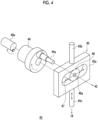
- Fig. 4 is a diagram schematically showing a disassembled perspective view of a main part of the motion conversion mechanism 43 of the cold head according to the embodiment.
- An exemplary form of the motion conversion mechanism 43 will be described with reference to Figs. 3 and 4 .
- the motion conversion mechanism 43 is a scotch yoke in this embodiment, and includes a crank 44 having a crank pin 44a, a scotch yoke shaft 45, and a crank pin bearing 46.
- the scotch yoke shaft 45 includes a scotch yoke plate 45a, an upper rod 45b, and a lower rod 45c.
- the scotch yoke shaft 45 may be formed of a metal material such as stainless steel.
- the crank 44 is fixed to the motor rotary shaft 40a.
- the crank pin 44a extends parallel to the motor rotary shaft 40a at a position eccentric from the motor rotary shaft 40a.
- the crank pin 44a extends from the crank 44 toward a side opposite to the motor rotary shaft 40a with respect to the crank 44.
- the scotch yoke plate 45a is a rectangular plate-shaped member having a horizontally elongated window 47.
- the horizontally elongated window 47 extends in the axial direction and in a direction perpendicular to the motor rotary shaft 40a.
- the crank pin bearing 46 is reliably disposed in the horizontally elongated window 47.
- the crank pin bearing 46 may be, for example, a roller bearing.
- An engagement hole 46a that engages with the crank pin 44a is formed at the center of the crank pin bearing 46, and the crank pin 44a penetrates the engagement hole 46a.
- the valve rotor 42a of the pressure switching valve 42 is disposed such that a center axis thereof coincides with the motor rotary shaft 40a, and a tip of the crank pin 44a penetrating the engagement hole 46a is fixed to the valve rotor 42a.
- the upper rod 45b extends upward from the center of an upper frame of the scotch yoke plate 45a
- the lower rod 45c extends downward from the center of a lower frame of the scotch yoke plate 45a
- the rods are coaxially disposed.
- the scotch yoke plate 45a and the upper rod 45b are accommodated in the expander housing 20, and the lower rod 45c extends out of the expander housing 20 by penetrating the lower cover 24.
- a tip of the lower rod 45c is connected to the displacer 18 inside the expander cylinder 16.
- a first sliding bearing 48a is provided between the upper rod 45b and the housing main body 22, and a second sliding bearing 48b is provided between the lower rod 45c and the lower cover 24.
- the housing main body 22 has a recessed portion for receiving the upper rod 45b in an upper portion thereof, and the first sliding bearing 48a is disposed in the recessed portion to slidably support the upper rod 45b in the axial direction.
- the lower cover 24 has a through-hole in a center portion thereof, and the second sliding bearing 48b is disposed in the through-hole to slidably support the lower rod 45c in the axial direction.
- the second sliding bearing 48b is provided with a seal portion such as a slipper seal or a clearance seal, and is configured to be airtight. Therefore, the housing internal volume 20a is isolated from the upper chamber 30. There is no direct gas flow between the housing internal volume 20a and the upper chamber 30.
- a collar portion 50 is fixed to the tip of the lower rod 45c connected to the displacer 18 by a fixing pin 49.
- the collar portion 50 is a short tubular member into which a tip of the displacer assembly 18 is inserted.
- a through-hole is formed in the tip of the lower rod 45c and the collar portion 50 in a direction perpendicular to the axial direction, and the collar portion 50 is fixed to the lower rod 45c by fitting the fixing pin 49 into the through-hole.
- the first displacer 18a has a lid portion 52a and a main body 52b.
- the lid portion 52a is an upper lid of the first displacer 18a, and has a disk shape.
- the lid portion 52a is formed of a metal material such as an alumite-treated aluminum alloy, or other material.
- the main body 52b has a cylindrical shape, and includes a regenerator therein.
- the main body 52b is formed of a synthetic resin material or other material, and may be formed of, for example, a phenolic resin such as Bakelite.
- the above-described working gas flow path 36a is formed by penetrating the lid portion 52a and an upper end portion of the main body 52b in the axial direction.
- the above-described first seal 38a may be interposed between outermost peripheral portions of the lid portion 52a and the main body 52b.
- the lid portion 52a and the main body 52b are fixed to each other by using, for example, a fastening member such as a bolt, or by using, for example, other methods such as adhesion.
- a through-hole for receiving the tip of the lower rod 45c and the collar portion 50 is formed in a center portion of the lid portion 52a.
- the collar portion 50 has a flange portion that expands outward in a radial direction at a lower end portion thereof, and the flange portion is interposed between the lid portion 52a and the main body 52b of the first displacer 18a, so that the lower rod 45c and the collar portion 50 are connected to the first displacer 18a. In this way, the displacer 18 is attached to the scotch yoke shaft 45.
- the crank pin bearing 46 engaged with the crank pin 44a rotates in a circular motion.
- the crank pin bearing 46 reciprocates in the horizontally elongated window 47 of the scotch yoke plate 45a, and the scotch yoke shaft 45 and the displacer 18 reciprocate in the axial direction.
- the expander motor 40 drives the axial movement of the scotch yoke shaft 45.
- the expander 14 includes a gas receiving port 54 different from the high pressure port 13a and the low pressure port 13b.
- the gas receiving port 54 is provided in the expander housing 20 and is connected to the connection flow path 20b to allow a gas to flow into the connection flow path 20b. Therefore, the gas receiving port 54 is provided not on the compressor 12 side (that is, on the high pressure port 13a and low pressure port 13b side) but on the expander cylinder 16 side with respect to the pressure switching valve 42.
- the gas receiving port 54 is not used in a normal operation of the cryocooler 10 for cryogenic cooling and is closed. As will be described below, the gas receiving port 54 is used in an open state in a gas replacement method for the expander 14 to return the cryocooler 10 from the maintenance work to the normal operation.
- the gas receiving port 54 is provided in the expander housing 20 and is therefore disposed outside the hermetic container 11. Therefore, in a state where the expander 14 is attached to the hermetic container 11, a worker can access the gas receiving port 54 from outside the hermetic container 11 and easily open and close the gas receiving port 54.
- the gas receiving port 54 may be a detachable coupling such as a self-sealing coupling. Accordingly, the pipe can be easily attached to and detached from the gas receiving port 54 for the gas replacement work of the expander 14.
- the gas receiving port 54 may have a size different from that of the high pressure port 13a and the low pressure port 13b, for example, a size smaller than that of the high pressure port 13a and the low pressure port 13b.
- the gas receiving port 54 may be a coupling having a size (for example, a nominal diameter) smaller than that of a coupling configuring the high pressure port 13a (or the low pressure port 13b). In this way, the gas receiving port 54 is easily identified by making the gas receiving port 54 different in size from other ports. This is helpful to prevent misconnection of the pipe between the gas receiving port 54 and other ports.
- a flow path cross-sectional area of the gas receiving port 54 may be smaller than a flow path cross-sectional area of the connection flow path 20b.
- the flow path cross-sectional area means a flow path cross-sectional area in a direction perpendicular to a flow direction of the working gas.
- the gas receiving port 54 (and a flow path volume from the gas receiving port 54 to the connection flow path 20b) is not used in the normal operation of the cryocooler 10, and thus can be a dead volume that can reduce a cooling capacity of the cryocooler 10. Therefore, such a dead volume can be reduced and the adverse effect on the cooling capacity of the cryocooler 10 can be reduced by making the flow path cross-sectional area of the gas receiving port 54 smaller than the flow path cross-sectional area of the connection flow path 20b.
- Fig. 5 is a flowchart showing the gas replacement method for the expander 14 of the cryocooler 10 according to the embodiment.
- Fig. 6 is a schematic view showing the expander 14 of the cryocooler 10 in the gas replacement method according to the embodiment.
- This gas replacement method can be executed while the operation of the cryocooler 10 is stopped, for example, before the normal operation of the cryocooler 10 is resumed after the maintenance work on the cryocooler 10 is performed.
- the expander 14 may be disassembled and reassembled in order to inspect or replace an internal component of the expander 14, such as the displacer assembly 18.
- the cryocooler 10 is mounted in a storage container for the cryogenic liquid and is used for recondensing the vaporized cryogenic liquid, when the maintenance work is performed at the site, the environmental atmosphere surrounding the cryocooler 10 may contain the vaporized cryogenic liquid. The gas can be taken into the expander 14 during the maintenance work.
- cryogenic liquid is liquid hydrogen
- hydrogen is a flammable gas. Therefore, a residual gas taken into the expander 14 may contain the flammable gas. Resuming the operation of the cryocooler 10 in this state (that is, starting the drive of the expander motor 40) cannot be said to avoid contact between the electrical equipment (that is, the expander motor 40) in the expander 14 and the flammable gas in that an internal volume of the expander 14 is not guaranteed to be filled only with the nonflammable gas.
- the gas replacement method for the expander 14 includes connecting the nonflammable gas source 60 to the connection flow path 20b (S10), and purging the residual gas in the expander cylinder 16 with the nonflammable gas from the nonflammable gas source 60 while the expander motor 40 is stopped (that is, in a state where energization to the expander motor 40 is stopped) (S20).
- S10 nonflammable gas source 60
- S20 purging the residual gas in the expander cylinder 16 with the nonflammable gas from the nonflammable gas source 60 while the expander motor 40 is stopped (that is, in a state where energization to the expander motor 40 is stopped)
- the working gas of the cryocooler 10 which is typically, for example, helium gas, as the nonflammable gas.
- the internal volume of the expander cylinder 16 can be filled with the working gas of the cryocooler 10 after the purging of the residual gas is completed, and the operation of the cryocooler 10 can be immediately resumed.
- the nonflammable gas source 60 is connected to the gas receiving port 54 of the connection flow path 20b via a gas replacement pipe 56.
- Fig. 6 shows an example of the connection between the expander 14 of the cryocooler 10 and the nonflammable gas source 60.
- the gas replacement pipe 56 includes a gas supply valve 57.
- the gas supply valve 57 is provided in a main pipe 56a of the gas replacement pipe 56.
- the nonflammable gas source 60 is connected to one end of the main pipe 56a, a coupling that is attachable to and detachable from the gas receiving port 54 of the expander 14 is provided at the other end of the main pipe 56a, and the main pipe 56a is connected to the gas receiving port 54 by the coupling.
- the nonflammable gas source 60 may be, for example, a gas cylinder filled with the nonflammable gas (for example, an inert gas such as helium gas) at a high pressure.
- the gas replacement pipe 56 includes a gas outlet port 58 branched from the main pipe 56a.
- the gas outlet port 58 may be, for example, an on-off valve. By opening the gas outlet port 58, the gas can be exhausted to the outside from the gas replacement pipe 56, and by closing the gas outlet port 58, the gas exhaust from the gas replacement pipe 56 is stopped.
- the nonflammable gas from the nonflammable gas source 60 is supplied to the expander cylinder 16 from the gas replacement pipe 56 through the gas receiving port 54.
- the residual gas in the expander cylinder 16 is exhausted from the gas outlet port 58 of the gas replacement pipe 56.
- the residual gas in the expander cylinder 16 is diluted by the supply of the nonflammable gas, and this diluted gas is exhausted from the expander cylinder 16. The supply of the nonflammable gas and the exhaust of the residual gas are performed while the expander motor 40 is stopped.
- the supply of the nonflammable gas and the exhaust of the residual gas may be simultaneously performed.
- the gas supply valve 57 and the gas outlet port 58 are simultaneously opened.
- the supply of the nonflammable gas and the exhaust of the residual gas may be alternately performed.
- a supply state in which the gas supply valve 57 is opened and the gas outlet port 58 is closed and an exhaust state in which the gas supply valve 57 is closed and the gas outlet port 58 is opened may be alternately repeated.
- the pressure switching valve 42 can take any of a first state in which the high pressure port 13a is connected to the expander cylinder 16, a second state in which the low pressure port 13b is connected to the expander cylinder 16, and a third state in which the expander cylinder 16 is connected to neither the high pressure port 13a nor the low pressure port 13b. Therefore, in the existing cryocooler in which the gas receiving port 54 is not provided, even when the nonflammable gas source is connected to the high pressure port 13a or the low pressure port 13b and the nonflammable gas is supplied from the port, it is not guaranteed that the purging of the residual gas in the expander cylinder 16 is realized. For example, in the third state, since both the high pressure port 13a and the low pressure port 13b are blocked from the expander cylinder 16 by the pressure switching valve 42, the nonflammable gas is not supplied into the expander cylinder 16.
- the nonflammable gas source 60 can be connected to the expander cylinder 16 via the gas replacement pipe 56 so as to be parallel to the pressure switching valve 42. Therefore, regardless of the state of the pressure switching valve 42, the residual gas in the expander cylinder 16 can be purged with the nonflammable gas from the nonflammable gas source 60, and the internal volume of the expander cylinder 16 can be reliably replaced with the nonflammable gas (for example, helium gas).
- the nonflammable gas for example, helium gas
- the cryocooler 10 can be returned from the maintenance work to the normal operation in a state of avoiding the contact between the electrical equipment in the expander 14 and the flammable gas.
- the nonflammable gas may be supplied to the expander 14 from the high pressure port 13a and the low pressure port 13b. This may be performed simultaneously with the supply of the nonflammable gas from the gas receiving port 54 to the expander cylinder 16. Alternatively, the supply from the gas receiving port 54, the supply from the high pressure port 13a, and the supply from the low pressure port 13b may be performed in any order, and may be performed in this order. In order to supply the nonflammable gas from the high pressure port 13a to the expander 14, the nonflammable gas source 60 may be connected to the high pressure port 13a by using the above-described gas replacement pipe 56.
- the nonflammable gas source 60 may be connected to the low pressure port 13b by using the above-described gas replacement pipe 56. In this way, the residual gas can be replaced with the nonflammable gas in the internal volume of the expander 14 connected to the high pressure port 13a and the low pressure port 13b.
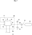
- Fig. 7 is a schematic view showing the expander 14 of the cryocooler 10 in the gas replacement method according to the embodiment.
- a three-pronged gas replacement pipe 56 may be used.
- the gas replacement pipe 56 may include a main pipe 56a that is connectable to the nonflammable gas source 60, a first branch pipe 56b that branches from the main pipe 56a and is connectable to the gas receiving port 54 of the expander 14, a second branch pipe 56c that branches from the main pipe 56a and is connectable to the high pressure port 13a of the expander 14, and a third branch pipe 56d that branches from the main pipe 56a and is connectable to the low pressure port 13b of the expander 14.
- the gas replacement pipe 56 may include the gas supply valve 57 in the main pipe 56a.
- the gas replacement pipe 56 may include the gas outlet port 58 branched from the main pipe 56a.
- the gas outlet port 59 may be provided in the expander 14 (for example, the expander housing 20).
- the gas replacement pipe 56 may include a pressure sensor 62 that measures the pressure of the gas supplied from the nonflammable gas source 60.
- Fig. 8 is a diagram schematically showing the cryocooler 10 according to the embodiment.
- Fig. 8 shows an internal structure of a drive unit of the cold head.
- a so-called gas assist type cryocooler 10 is known in which a gas assist chamber 64, which is a hermetic space, is formed between the upper rod 45b of the scotch yoke shaft 45 and the expander housing 20.
- the gas assist chamber 64 is connected to the high pressure port 13a and the low pressure port 13b via the pressure switching valve 42, similarly to the expander cylinder 16. Therefore, a second connection flow path 20c that connects the pressure switching valve 42 to the gas assist chamber 64 is formed in the expander housing 20.
- the pressure switching valve 42 is configured to alternately connect the high pressure port 13a and the low pressure port 13b to the gas assist chamber 64.
- a differential pressure that periodically acts between the gas assist chamber 64 and the internal volume of the expander housing 20 can assist the axial reciprocation of the scotch yoke shaft 45, that is, the displacer 18.
- the expander 14 including such a gas assist chamber 64 may include a second gas receiving port 55 connected to the second connection flow path 20c in addition to a first gas receiving port 54 connected to the first connection flow path 20b.
- the gas replacement method according to the embodiment may be applied to the gas assist chamber 64 through the second gas receiving port 55. In this way, the residual gas in the gas assist chamber 64 can be purged with the nonflammable gas.
- a four-pronged gas replacement pipe may be used in which a fourth branch pipe that branches from the main pipe 56a and is connectable to the gas assist chamber 64 of the expander 14 is added to the gas replacement pipe 56 shown in Fig. 7 .
- the nonflammable gas source 60 is connected to the connection flow path 20b through the gas receiving port 54 by using the gas replacement pipe 56 as an example, but other connection configurations are also possible.
- the nonflammable gas source 60 may be connected to the expander cylinder 16 instead of the connection flow path 20b.
- the gas receiving port 54 may be provided in the expander cylinder 16.
- the gas replacement pipe 56 may be provided to penetrate a wall of the hermetic container 11 in order to connect the gas receiving port 54 disposed inside the hermetic container 11 to the nonflammable gas source 60 disposed outside the hermetic container 11.
- cryocooler 10 is a two-stage GM cryocooler
- the cryocooler 10 according to the embodiment may be, for example, a single-stage GM cryocooler (providing cryogenic cooling of, for example, 20 K to 80 K), or any other cryocooler including a pressure switching valve in an expander. Even in such a case, the gas replacement method according to the embodiment can be similarly applied.
Landscapes
- Engineering & Computer Science (AREA)
- Physics & Mathematics (AREA)
- Mechanical Engineering (AREA)
- Thermal Sciences (AREA)
- General Engineering & Computer Science (AREA)
- Compressors, Vaccum Pumps And Other Relevant Systems (AREA)
- Filling Or Discharging Of Gas Storage Vessels (AREA)
Abstract
There is provided a gas replacement technique for an expander (14) of a cryocooler (10) for avoiding contact between electrical equipment in the expander (14) and a flammable gas. A gas replacement method for an expander (14) of a cryocooler (10) is provided. The expander (14) includes an expander cylinder (16), a pressure switching valve (42) that switches a pressure inside the expander cylinder (16), a connection flow path (20b) from the pressure switching valve (42) to the expander cylinder (16), and an expander motor (40) that drives the pressure switching valve (42). The method includes connecting a nonflammable gas source (60) to the connection flow path (20b) or the expander cylinder (16), and purging a residual gas in the expander cylinder (16) with a nonflammable gas from the nonflammable gas source (60) while the expander motor (40) is stopped.
Description
- The present invention relates to a gas replacement method for an expander of a cryocooler and a cryocooler. In addition, the present invention relates to a gas replacement pipe that can be used in such a gas replacement method.
- For example, a cryocooler such as a Gifford-McMahon (GM) cryocooler is mounted in a storage container for a liquefied gas and used for recondensing the gas as one of applications thereof (for example,
Japanese Unexamined Patent Publication No. 2001-241796 - In a case where the gas to be recondensed by the cryocooler contains, for example, a flammable gas such as hydrogen, an atmosphere surrounding the cryocooler may contain the flammable gas. The present inventor has noticed that the flammable gas may be taken into an expander of the cryocooler during maintenance work that is performed by interrupting an operation of the cryocooler. The maintenance work involves disassembling and reassembling the expander to inspect or replace an internal component. Therefore, in a case where the maintenance work is performed at a site where the expander is installed, an ambient gas, that is, a gas that may contain the flammable gas, may be taken into the expander. As a result, electrical equipment in the expander, such as a motor, and the flammable gas may come into contact with each other. Operating the electrical equipment in a state of being in contact with the flammable gas may cause a risk of ignition.
- An exemplary object of one aspect of the present invention is to provide a gas replacement technique for an expander of a cryocooler for avoiding contact between electrical equipment in the expander and a flammable gas.
- According to one aspect of the present invention, there is provided a gas replacement method for an expander of a cryocooler. The expander includes an expander cylinder, a pressure switching valve that switches a pressure inside the expander cylinder, a connection flow path from the pressure switching valve to the expander cylinder, and an expander motor that drives the pressure switching valve. The method includes connecting a nonflammable gas source to the connection flow path or the expander cylinder, and purging a residual gas in the expander cylinder with a nonflammable gas from the nonflammable gas source while the expander motor is stopped.
- According to another aspect of the present invention, there is provided a cryocooler including an expander cylinder, a pressure switching valve that switches a pressure inside the expander cylinder, a high pressure port and a low pressure port connected to the expander cylinder via the pressure switching valve, a connection flow path from the pressure switching valve to the expander cylinder, and a gas receiving port that is different from the high pressure port and the low pressure port and is connected to the connection flow path to allow a gas to flow into the connection flow path.
- According to still another aspect of the present invention, there is provided a gas replacement pipe used for gas replacement of an expander of a cryocooler. The gas replacement pipe includes a main pipe that is connectable to a nonflammable gas source, a first branch pipe that branches from the main pipe and is connectable to a gas receiving port of the expander, a second branch pipe that branches from the main pipe and is connectable to a high pressure port of the expander, and a third branch pipe that branches from the main pipe and is connectable to a low pressure port of the expander.
- According to the present invention, it is possible to provide a gas replacement technique for an expander of a cryocooler for avoiding contact between electrical equipment in the expander and a flammable gas.
-
-
Fig. 1 is a diagram schematically showing a cryocooler according to an embodiment. -
Fig. 2 is a diagram schematically showing the cryocooler according to the embodiment. -
Fig. 3 is a diagram schematically showing the cryocooler according to the embodiment. -
Fig. 4 is a diagram schematically showing a disassembled perspective view of a main part of a motion conversion mechanism of a cold head according to the embodiment. -
Fig. 5 is a flowchart showing a gas replacement method for an expander of the cryocooler according to the embodiment. -
Fig. 6 is a schematic view showing the expander of the cryocooler in the gas replacement method according to the embodiment. -
Fig. 7 is a schematic view showing the expander of the cryocooler in the gas replacement method according to the embodiment. -
Fig. 8 is a diagram schematically showing the cryocooler according to the embodiment. - Hereinafter, an embodiment for carrying out the present invention will be described in detail with reference to the drawings. In the description and the drawings, the same or equivalent components, members, and processes are denoted by the same reference numerals, and overlapping description is omitted as appropriate. The scale and the shape of each of parts shown in the drawings are set for convenience to make the description easy to understand, and are not to be interpreted as limiting unless stated otherwise. The embodiment is merely an example and does not limit the scope of the present invention. All features described in the embodiment or combinations thereof are not necessarily essential to the present invention.
-
Figs. 1 to 3 are diagrams schematically showing acryocooler 10 according to the embodiment.Fig. 1 shows an appearance of a cold head of thecryocooler 10, andFig. 2 shows an internal structure of a low-temperature section of the cold head.Fig. 3 shows an internal structure of a drive unit of the cold head. Thecryocooler 10 is usually installed in a vacuum chamber (not shown) such that the low-temperature section is disposed inside the vacuum chamber and the drive unit is disposed in a surrounding environment (for example, a room temperature atmospheric pressure environment) outside the vacuum chamber. As an example, thecryocooler 10 is a two-stage Gifford-McMahon (GM) cryocooler. - As an example of applications, the
cryocooler 10 may be mounted in a cryogenic liquid storage tank that stores a cryogenic liquid. Thecryocooler 10 may be used for recondensing a vaporized cryogenic liquid. The cryogenic liquid may be a refrigerant having a boiling point lower than a boiling point of nitrogen (about 77 K) in the embodiment, and may be, for example, liquid hydrogen, liquid helium, or liquid neon. - The
cryocooler 10 includes acompressor 12 and anexpander 14. Thecompressor 12 is configured to collect a working gas of thecryocooler 10 from theexpander 14, to pressurize the collected working gas, and to supply the working gas to theexpander 14 again. Thecompressor 12 and theexpander 14 constitute a refrigeration cycle of thecryocooler 10, whereby thecryocooler 10 can provide desired cryogenic cooling. Theexpander 14 is also often referred to as a cold head. The working gas is also referred to as a refrigerant gas, and other suitable gases may be used although a helium gas is typically used. For the sake of understanding, a flow direction of the working gas is shown by an arrow inFig. 1 . - In general, both a pressure of a working gas supplied from the
compressor 12 to theexpander 14 and a pressure of a working gas collected from theexpander 14 to thecompressor 12 are considerably higher than the atmospheric pressure, and can be called a first high pressure and a second high pressure, respectively. For convenience of description, the first high pressure and the second high pressure are also simply called a high pressure and a low pressure, respectively. Typically, the high pressure is, for example, 2 to 3 MPa. The low pressure is, for example, 0.5 to 1.5 MPa and is, for example, about 0.8 MPa. For the sake of understanding, a flow direction of the working gas is shown by an arrow. - The
expander 14 includes anexpander cylinder 16, a displacer assembly (hereinafter, also referred to as a displacer) 18, and an expander housing (hereinafter, also referred to as a housing) 20. The expandercylinder 16 guides linear reciprocation of thedisplacer 18, and forms an expansion chamber (32, 34) as an expansion space for the working gas in a space with thedisplacer 18. Theexpander cylinder 16 is fixed to theexpander housing 20, whereby a casing of theexpander 14 is configured, and an airtight space for accommodating thedisplacer 18 is formed inside theexpander cylinder 16. - In addition, the
expander 14 includes ahigh pressure port 13a and alow pressure port 13b. Thehigh pressure port 13a is provided in theexpander housing 20 as an inlet for the working gas to theexpander 14, and thelow pressure port 13b is provided in theexpander housing 20 as an outlet for the working gas from theexpander 14. Therefore, thehigh pressure port 13a is connected to a high pressure side of thecompressor 12 by a high pressure side pipe, and thelow pressure port 13b is connected to a low pressure side of thecompressor 12 by a low pressure side pipe. Accordingly, the high pressure working gas is supplied from the high pressure side of thecompressor 12 to the expander 14 through thehigh pressure port 13a. In addition, the low pressure working gas is collected from theexpander 14 to the low pressure side of thecompressor 12 through thelow pressure port 13b. - In the present specification, in order to describe a positional relationship between the components of the
cryocooler 10, for convenience, a side close to a top dead center of the axial reciprocation of the displacer is described as "upper", and a side close to a bottom dead center is described as "lower". The top dead center is a position of the displacer where a volume of an expansion space is maximized, and the bottom dead center is the position of the displacer where the volume of the expansion space is minimized. Since a temperature gradient is generated in which a temperature drops from the upper side to the lower side in the axial direction during the operation of thecryocooler 10, the upper side can be referred to as a high temperature side and the lower side can be referred to as a low temperature side. - The
expander cylinder 16 includes afirst cylinder 16a and asecond cylinder 16b. As an example, thefirst cylinder 16a and thesecond cylinder 16b are members having a cylindrical shape, and thesecond cylinder 16b has a smaller diameter than thefirst cylinder 16a. Thefirst cylinder 16a and thesecond cylinder 16b are coaxially disposed, and a lower end of thefirst cylinder 16a is rigidly connected to an upper end of thesecond cylinder 16b. - The
displacer assembly 18 includes afirst displacer 18a and asecond displacer 18b, which are connected to each other, and these move integrally. As an example, thefirst displacer 18a and thesecond displacer 18b are members having a cylindrical shape, and thesecond displacer 18b has a smaller diameter than thefirst displacer 18a. Thefirst displacer 18a and thesecond displacer 18b are coaxially disposed. - The
first displacer 18a is accommodated in thefirst cylinder 16a, and thesecond displacer 18b is accommodated in thesecond cylinder 16b. Thefirst displacer 18a can reciprocate in an axial direction along thefirst cylinder 16a, and thesecond displacer 18b can reciprocate in the axial direction along thesecond cylinder 16b. - As shown in
Fig. 2 , thefirst displacer 18a accommodates afirst regenerator 26. Thefirst regenerator 26 is formed by filling a tubular main body of thefirst displacer 18a with a wire mesh such as copper or other appropriate first regenerator material. An upper lid portion and a lower lid portion of thefirst displacer 18a may be provided as separate members from the main body of thefirst displacer 18a, and the upper lid portion and the lower lid portion of thefirst displacer 18a may be fixed to the main body by appropriate means such as fastening or welding, whereby the first regenerator material may be accommodated in thefirst displacer 18a. - Similarly, the
second displacer 18b accommodates asecond regenerator 28. Thesecond regenerator 28 is formed by filling a tubular main body of thesecond displacer 18b with a non-magnetic regenerator material such as bismuth, a magnetic regenerator material such as HoCu2, or other appropriate second regenerator material. The second regenerator material may be formed in a granular shape. The upper lid portion and the lower lid portion of thesecond displacer 18b may be provided as separate members from the main body of thesecond displacer 18b, and the lower lid portion and the upper lid portion of thesecond displacer 18b may be fixed to the main body by appropriate means such as fastening or welding, whereby the second regenerator material may be accommodated in thesecond displacer 18b. - The
displacer 18 forms anupper chamber 30, afirst expansion chamber 32, and asecond expansion chamber 34 inside theexpander cylinder 16. Theexpander 14 includes afirst cooling stage 33 and asecond cooling stage 35 for heat exchange with a desired object or medium to be cooled by thecryocooler 10. Theupper chamber 30 is formed between the upper lid portion of thefirst displacer 18a and the upper portion of thefirst cylinder 16a. Thefirst expansion chamber 32 is formed between the lower lid portion of thefirst displacer 18a and thefirst cooling stage 33. Thesecond expansion chamber 34 is formed between the lower lid portion of thesecond displacer 18b and thesecond cooling stage 35. Thefirst cooling stage 33 is fixed to the lower portion of thefirst cylinder 16a to surround thefirst expansion chamber 32, and thesecond cooling stage 35 is fixed to the lower portion of thesecond cylinder 16b to surround thesecond expansion chamber 34. - The
first regenerator 26 is connected to theupper chamber 30 through a workinggas flow path 36a formed in the upper lid portion of thefirst displacer 18a, and is connected to thefirst expansion chamber 32 through a workinggas flow path 36b formed in the lower lid portion of thefirst displacer 18a. Thesecond regenerator 28 is connected to thefirst regenerator 26 through a workinggas flow path 36c formed from the lower lid portion of thefirst displacer 18a to the upper lid portion of thesecond displacer 18b. In addition, thesecond regenerator 28 is connected to thesecond expansion chamber 34 through a workinggas flow path 36d formed in the lower lid portion of thesecond displacer 18b. - A
first seal 38a and asecond seal 38b may be provided so that the working gas flow between thefirst expansion chamber 32, thesecond expansion chamber 34 and theupper chamber 30 is guided to thefirst regenerator 26 and thesecond regenerator 28 rather than to the clearance between theexpander cylinder 16 and thedisplacer 18. Thefirst seal 38a may be mounted to the upper lid portion of thefirst displacer 18a to be disposed between thefirst displacer 18a and thefirst cylinder 16a. Thesecond seal 38b may be mounted to the upper lid portion of thesecond displacer 18b to be disposed between thesecond displacer 18b and thesecond cylinder 16b. - As shown in
Fig. 3 , theexpander housing 20 includes a housingmain body 22 having alower opening 21 and alower cover 24 that closes thelower opening 21. Thelower opening 21 is formed on a lower surface of the housingmain body 22. As shown in the figure, a housinginternal volume 20a formed by the housingmain body 22 and thelower cover 24 may be connected to a low pressure side of thecompressor 12 and maintained at a low pressure. - The
lower cover 24 partitions the housinginternal volume 20a and a displacer accommodation space (upper chamber 30) in theexpander cylinder 16. Thelower cover 24 has a disk shape as a whole, and more specifically, has an upper large-diameter portion and a lower small-diameter portion. Afirst sealing member 25a is provided between thelower cover 24 and theexpander cylinder 16 in order to maintain airtightness of an internal volume of theexpander cylinder 16, and asecond sealing member 25b is provided between thelower cover 24 and the housingmain body 22 in order to maintain airtightness of the housinginternal volume 20a. As shown in the figure, thefirst sealing member 25a may be mounted to the small-diameter portion of thelower cover 24, and thesecond sealing member 25b may be mounted to the large-diameter portion of thelower cover 24. - The
lower cover 24 is removably fitted into thelower opening 21, and an upper flange portion of theexpander cylinder 16 is fastened to the housingmain body 22 with a fastening member such as a bolt. In this way, thelower cover 24 is interposed between the housingmain body 22 and the upper flange portion of theexpander cylinder 16. Thelower cover 24 is not fixed to the housingmain body 22 through fastening. Note that a structure may be adopted in which the housingmain body 22 and thelower cover 24 are fastened to each other with a fastening member such as a bolt. - In addition, the
expander 14 includes anexpander motor 40, apressure switching valve 42, and amotion conversion mechanism 43. Theexpander motor 40 is attached to theexpander housing 20, more specifically, to a side surface of the housingmain body 22. In order to maintain the airtightness of the housinginternal volume 20a, a sealing member (not shown) may be provided on an attachment surface between theexpander motor 40 and the housingmain body 22. Thepressure switching valve 42 and themotion conversion mechanism 43 are accommodated in theexpander housing 20. - The
expander motor 40 is provided in theexpander 14 as a drive source for thedisplacer 18 and thepressure switching valve 42. Theexpander motor 40 may be an appropriate electric motor, and may be configured to rotate amotor rotary shaft 40a at a constant rotational speed, or may be capable of variably controlling the rotational speed of themotor rotary shaft 40a. - The
pressure switching valve 42 connects thehigh pressure port 13a and thelow pressure port 13b to the expander cylinder 16 (that is, theupper chamber 30, thefirst expansion chamber 32, and the second expansion chamber 34). Thepressure switching valve 42 is configured to alternately connect thehigh pressure port 13a and thelow pressure port 13b to theexpander cylinder 16 and to periodically switch between the intake and the exhaust of theexpander cylinder 16. - In addition, the
pressure switching valve 42 may be configured to temporarily block the connection between both thehigh pressure port 13a and thelow pressure port 13b and theexpander cylinder 16 when switching the connection between thehigh pressure port 13a and thelow pressure port 13b. In this case, thepressure switching valve 42 does not instantaneously switch the connection between thehigh pressure port 13a and thelow pressure port 13b, but has a period in which theexpander cylinder 16 is connected to neither thehigh pressure port 13a nor thelow pressure port 13b. - The
pressure switching valve 42 is a rotary valve type in the embodiment. Therefore, thepressure switching valve 42 includes avalve rotor 42a and avalve stator 42b, and thevalve rotor 42a is in contact with thevalve stator 42b so as to rotate while sliding with respect to thevalve stator 42b. Thevalve rotor 42a is supported to be rotatable with respect to the housingmain body 22, and thevalve stator 42b is supported to be unrotatable with respect to the housingmain body 22. An elastic body such as a spring for pressing thevalve stator 42b toward thevalve rotor 42a in a direction of a rotation axis of thevalve rotor 42a may be interposed between thevalve stator 42b and the housingmain body 22. - A
connection flow path 20b from thepressure switching valve 42 to theexpander cylinder 16 is formed in theexpander housing 20. Theconnection flow path 20b connects thepressure switching valve 42 to theupper chamber 30. Thevalve rotor 42a and thevalve stator 42b of thepressure switching valve 42 are formed with a valve internal flow path to alternately connect theconnection flow path 20b to thehigh pressure port 13a and the housinginternal volume 20a (that is, thelow pressure port 13b). Various known forms can be adopted as the valve internal flow path, and details thereof will not be described herein. - The
motion conversion mechanism 43 is configured to connect theexpander motor 40 to thepressure switching valve 42 and thedisplacer 18 so as to transmit the rotation of themotor rotary shaft 40a to thepressure switching valve 42 and convert the rotation into the linear reciprocation of thedisplacer 18. An example of themotion conversion mechanism 43 will be described below. One rotation of themotor rotary shaft 40a causes one reciprocation of thedisplacer 18 via themotion conversion mechanism 43, thereby periodically changing the volume of the expansion space for the working gas. Simultaneously, one rotation of themotor rotary shaft 40a causes one rotation of thepressure switching valve 42 via themotion conversion mechanism 43, whereby thehigh pressure port 13a and thelow pressure port 13b are alternately connected to theexpander cylinder 16 via thepressure switching valve 42, and the pressure of the expansion space for the working gas periodically changes. - In this way, the synchronized volume fluctuation and pressure fluctuation are generated in the expansion space to configure the refrigeration cycle of the
cryocooler 10, whereby thecryocooler 10 can provide desired cryogenic cooling. Thefirst cooling stage 33 can be cooled to a first cooling temperature, and thesecond cooling stage 35 can be cooled to a second cooling temperature lower than the first cooling temperature. The first cooling temperature may be, for example, in a range of about 10 K to about 100 K or in a range of about 20 K to about 40 K. The second cooling temperature may be, for example, about 20 K or lower, or about 10 K or lower, or in a range of about 1 K to about 4 K. In a case where thecryocooler 10 is used for recondensing the vaporized cryogenic liquid, a cooling temperature of the cryocooler 10 (for example, the second cooling temperature) may be a temperature equal to or lower than a boiling point of the cryogenic liquid. - The
expander 14 of thecryocooler 10 may be installed in ahermetic container 11 as illustrated inFig. 1 . Thehermetic container 11 may be, for example, a vacuum chamber such as a cryostat. In a case where thecryocooler 10 is used for recondensing the vaporized cryogenic liquid, thehermetic container 11 may configure a cryogenic liquid storage tank that stores the cryogenic liquid. Theexpander 14 may be inserted into thehermetic container 11 from an opening portion of a wall surface of thehermetic container 11, and theexpander housing 20 may be fixed to thehermetic container 11 at the opening portion. Theexpander housing 20 is exposed to ambient environment (for example, room temperature atmospheric pressure environment) of thehermetic container 11, and thefirst cooling stage 33 and thesecond cooling stage 35 are disposed inside thehermetic container 11. Theexpander 14 may be vertically installed in thehermetic container 11 such that theexpander housing 20 faces upward and thefirst cooling stage 33 and thesecond cooling stage 35 face downward. -
Fig. 4 is a diagram schematically showing a disassembled perspective view of a main part of themotion conversion mechanism 43 of the cold head according to the embodiment. An exemplary form of themotion conversion mechanism 43 will be described with reference toFigs. 3 and4 . - The
motion conversion mechanism 43 is a scotch yoke in this embodiment, and includes a crank 44 having a crankpin 44a, ascotch yoke shaft 45, and acrank pin bearing 46. Thescotch yoke shaft 45 includes ascotch yoke plate 45a, anupper rod 45b, and alower rod 45c. Thescotch yoke shaft 45 may be formed of a metal material such as stainless steel. - The
crank 44 is fixed to themotor rotary shaft 40a. Thecrank pin 44a extends parallel to themotor rotary shaft 40a at a position eccentric from themotor rotary shaft 40a. Thecrank pin 44a extends from thecrank 44 toward a side opposite to themotor rotary shaft 40a with respect to thecrank 44. - The
scotch yoke plate 45a is a rectangular plate-shaped member having a horizontally elongatedwindow 47. The horizontally elongatedwindow 47 extends in the axial direction and in a direction perpendicular to themotor rotary shaft 40a. The crank pin bearing 46 is reliably disposed in the horizontally elongatedwindow 47. The crank pin bearing 46 may be, for example, a roller bearing. Anengagement hole 46a that engages with thecrank pin 44a is formed at the center of the crank pin bearing 46, and thecrank pin 44a penetrates theengagement hole 46a. - On a side opposite to the crank 44 with respect to the
scotch yoke plate 45a, thevalve rotor 42a of thepressure switching valve 42 is disposed such that a center axis thereof coincides with themotor rotary shaft 40a, and a tip of thecrank pin 44a penetrating theengagement hole 46a is fixed to thevalve rotor 42a. - The
upper rod 45b extends upward from the center of an upper frame of thescotch yoke plate 45a, thelower rod 45c extends downward from the center of a lower frame of thescotch yoke plate 45a, and the rods are coaxially disposed. Thescotch yoke plate 45a and theupper rod 45b are accommodated in theexpander housing 20, and thelower rod 45c extends out of theexpander housing 20 by penetrating thelower cover 24. A tip of thelower rod 45c is connected to thedisplacer 18 inside theexpander cylinder 16. - A first sliding
bearing 48a is provided between theupper rod 45b and the housingmain body 22, and a second slidingbearing 48b is provided between thelower rod 45c and thelower cover 24. The housingmain body 22 has a recessed portion for receiving theupper rod 45b in an upper portion thereof, and the first slidingbearing 48a is disposed in the recessed portion to slidably support theupper rod 45b in the axial direction. Thelower cover 24 has a through-hole in a center portion thereof, and the second slidingbearing 48b is disposed in the through-hole to slidably support thelower rod 45c in the axial direction. The second slidingbearing 48b is provided with a seal portion such as a slipper seal or a clearance seal, and is configured to be airtight. Therefore, the housinginternal volume 20a is isolated from theupper chamber 30. There is no direct gas flow between the housinginternal volume 20a and theupper chamber 30. - A
collar portion 50 is fixed to the tip of thelower rod 45c connected to thedisplacer 18 by a fixingpin 49. Thecollar portion 50 is a short tubular member into which a tip of thedisplacer assembly 18 is inserted. A through-hole is formed in the tip of thelower rod 45c and thecollar portion 50 in a direction perpendicular to the axial direction, and thecollar portion 50 is fixed to thelower rod 45c by fitting the fixingpin 49 into the through-hole. - The
first displacer 18a has alid portion 52a and amain body 52b. Thelid portion 52a is an upper lid of thefirst displacer 18a, and has a disk shape. Thelid portion 52a is formed of a metal material such as an alumite-treated aluminum alloy, or other material. Themain body 52b has a cylindrical shape, and includes a regenerator therein. Themain body 52b is formed of a synthetic resin material or other material, and may be formed of, for example, a phenolic resin such as Bakelite. The above-described workinggas flow path 36a is formed by penetrating thelid portion 52a and an upper end portion of themain body 52b in the axial direction. The above-describedfirst seal 38a may be interposed between outermost peripheral portions of thelid portion 52a and themain body 52b. Thelid portion 52a and themain body 52b are fixed to each other by using, for example, a fastening member such as a bolt, or by using, for example, other methods such as adhesion. - A through-hole for receiving the tip of the
lower rod 45c and thecollar portion 50 is formed in a center portion of thelid portion 52a. Thecollar portion 50 has a flange portion that expands outward in a radial direction at a lower end portion thereof, and the flange portion is interposed between thelid portion 52a and themain body 52b of thefirst displacer 18a, so that thelower rod 45c and thecollar portion 50 are connected to thefirst displacer 18a. In this way, thedisplacer 18 is attached to thescotch yoke shaft 45. - Therefore, when the
expander motor 40 is driven and themotor rotary shaft 40a is rotated, the crank pin bearing 46 engaged with thecrank pin 44a rotates in a circular motion. In this case, the crank pin bearing 46 reciprocates in the horizontally elongatedwindow 47 of thescotch yoke plate 45a, and thescotch yoke shaft 45 and thedisplacer 18 reciprocate in the axial direction. In this way, theexpander motor 40 drives the axial movement of thescotch yoke shaft 45. - In the embodiment, as shown in
Figs. 1 and3 , theexpander 14 includes agas receiving port 54 different from thehigh pressure port 13a and thelow pressure port 13b. Thegas receiving port 54 is provided in theexpander housing 20 and is connected to theconnection flow path 20b to allow a gas to flow into theconnection flow path 20b. Therefore, thegas receiving port 54 is provided not on thecompressor 12 side (that is, on thehigh pressure port 13a andlow pressure port 13b side) but on theexpander cylinder 16 side with respect to thepressure switching valve 42. - The
gas receiving port 54 is not used in a normal operation of thecryocooler 10 for cryogenic cooling and is closed. As will be described below, thegas receiving port 54 is used in an open state in a gas replacement method for theexpander 14 to return thecryocooler 10 from the maintenance work to the normal operation. - The
gas receiving port 54 is provided in theexpander housing 20 and is therefore disposed outside thehermetic container 11. Therefore, in a state where theexpander 14 is attached to thehermetic container 11, a worker can access thegas receiving port 54 from outside thehermetic container 11 and easily open and close thegas receiving port 54. - As with the
high pressure port 13a and thelow pressure port 13b, thegas receiving port 54 may be a detachable coupling such as a self-sealing coupling. Accordingly, the pipe can be easily attached to and detached from thegas receiving port 54 for the gas replacement work of theexpander 14. - The
gas receiving port 54 may have a size different from that of thehigh pressure port 13a and thelow pressure port 13b, for example, a size smaller than that of thehigh pressure port 13a and thelow pressure port 13b. For example, thegas receiving port 54 may be a coupling having a size (for example, a nominal diameter) smaller than that of a coupling configuring thehigh pressure port 13a (or thelow pressure port 13b). In this way, thegas receiving port 54 is easily identified by making thegas receiving port 54 different in size from other ports. This is helpful to prevent misconnection of the pipe between thegas receiving port 54 and other ports. - A flow path cross-sectional area of the
gas receiving port 54 may be smaller than a flow path cross-sectional area of theconnection flow path 20b. Here, the flow path cross-sectional area means a flow path cross-sectional area in a direction perpendicular to a flow direction of the working gas. The gas receiving port 54 (and a flow path volume from thegas receiving port 54 to theconnection flow path 20b) is not used in the normal operation of thecryocooler 10, and thus can be a dead volume that can reduce a cooling capacity of thecryocooler 10. Therefore, such a dead volume can be reduced and the adverse effect on the cooling capacity of thecryocooler 10 can be reduced by making the flow path cross-sectional area of thegas receiving port 54 smaller than the flow path cross-sectional area of theconnection flow path 20b. -
Fig. 5 is a flowchart showing the gas replacement method for theexpander 14 of thecryocooler 10 according to the embodiment.Fig. 6 is a schematic view showing theexpander 14 of thecryocooler 10 in the gas replacement method according to the embodiment. - This gas replacement method can be executed while the operation of the
cryocooler 10 is stopped, for example, before the normal operation of thecryocooler 10 is resumed after the maintenance work on thecryocooler 10 is performed. In the maintenance work, for example, theexpander 14 may be disassembled and reassembled in order to inspect or replace an internal component of theexpander 14, such as thedisplacer assembly 18. In a case where thecryocooler 10 is mounted in a storage container for the cryogenic liquid and is used for recondensing the vaporized cryogenic liquid, when the maintenance work is performed at the site, the environmental atmosphere surrounding thecryocooler 10 may contain the vaporized cryogenic liquid. The gas can be taken into theexpander 14 during the maintenance work. In a case where the cryogenic liquid is liquid hydrogen, hydrogen is a flammable gas. Therefore, a residual gas taken into theexpander 14 may contain the flammable gas. Resuming the operation of thecryocooler 10 in this state (that is, starting the drive of the expander motor 40) cannot be said to avoid contact between the electrical equipment (that is, the expander motor 40) in theexpander 14 and the flammable gas in that an internal volume of theexpander 14 is not guaranteed to be filled only with the nonflammable gas. - The gas replacement method for the
expander 14 according to the embodiment includes connecting thenonflammable gas source 60 to theconnection flow path 20b (S10), and purging the residual gas in theexpander cylinder 16 with the nonflammable gas from thenonflammable gas source 60 while theexpander motor 40 is stopped (that is, in a state where energization to theexpander motor 40 is stopped) (S20). In addition, in this method, when the purging of the residual gas is completed, the connection between thenonflammable gas source 60 and theconnection flow path 20b is released, and the operation of thecryocooler 10 is resumed. - Here, it is convenient to use the working gas of the
cryocooler 10, which is typically, for example, helium gas, as the nonflammable gas. In this way, the internal volume of theexpander cylinder 16 can be filled with the working gas of thecryocooler 10 after the purging of the residual gas is completed, and the operation of thecryocooler 10 can be immediately resumed. - In S10, the
nonflammable gas source 60 is connected to thegas receiving port 54 of theconnection flow path 20b via agas replacement pipe 56.Fig. 6 shows an example of the connection between theexpander 14 of thecryocooler 10 and thenonflammable gas source 60. - The
gas replacement pipe 56 includes agas supply valve 57. Thegas supply valve 57 is provided in amain pipe 56a of thegas replacement pipe 56. Thenonflammable gas source 60 is connected to one end of themain pipe 56a, a coupling that is attachable to and detachable from thegas receiving port 54 of theexpander 14 is provided at the other end of themain pipe 56a, and themain pipe 56a is connected to thegas receiving port 54 by the coupling. By opening thegas supply valve 57, the nonflammable gas is supplied from thenonflammable gas source 60 to thegas receiving port 54, and by closing thegas supply valve 57, the supply of the nonflammable gas is stopped. Thenonflammable gas source 60 may be, for example, a gas cylinder filled with the nonflammable gas (for example, an inert gas such as helium gas) at a high pressure. - In addition, the
gas replacement pipe 56 includes agas outlet port 58 branched from themain pipe 56a. Thegas outlet port 58 may be, for example, an on-off valve. By opening thegas outlet port 58, the gas can be exhausted to the outside from thegas replacement pipe 56, and by closing thegas outlet port 58, the gas exhaust from thegas replacement pipe 56 is stopped. - In S20, the nonflammable gas from the
nonflammable gas source 60 is supplied to theexpander cylinder 16 from thegas replacement pipe 56 through thegas receiving port 54. In addition, the residual gas in theexpander cylinder 16 is exhausted from thegas outlet port 58 of thegas replacement pipe 56. In other words, the residual gas in theexpander cylinder 16 is diluted by the supply of the nonflammable gas, and this diluted gas is exhausted from theexpander cylinder 16. The supply of the nonflammable gas and the exhaust of the residual gas are performed while theexpander motor 40 is stopped. - The supply of the nonflammable gas and the exhaust of the residual gas may be simultaneously performed. In this case, the
gas supply valve 57 and thegas outlet port 58 are simultaneously opened. Alternatively, the supply of the nonflammable gas and the exhaust of the residual gas may be alternately performed. In this case, a supply state in which thegas supply valve 57 is opened and thegas outlet port 58 is closed and an exhaust state in which thegas supply valve 57 is closed and thegas outlet port 58 is opened may be alternately repeated. - When the
cryocooler 10 is stopped, thepressure switching valve 42 can take any of a first state in which thehigh pressure port 13a is connected to theexpander cylinder 16, a second state in which thelow pressure port 13b is connected to theexpander cylinder 16, and a third state in which theexpander cylinder 16 is connected to neither thehigh pressure port 13a nor thelow pressure port 13b. Therefore, in the existing cryocooler in which thegas receiving port 54 is not provided, even when the nonflammable gas source is connected to thehigh pressure port 13a or thelow pressure port 13b and the nonflammable gas is supplied from the port, it is not guaranteed that the purging of the residual gas in theexpander cylinder 16 is realized. For example, in the third state, since both thehigh pressure port 13a and thelow pressure port 13b are blocked from theexpander cylinder 16 by thepressure switching valve 42, the nonflammable gas is not supplied into theexpander cylinder 16. - On the other hand, according to the embodiment, since the
gas receiving port 54 is connected to theconnection flow path 20b from thepressure switching valve 42 to theexpander cylinder 16, thenonflammable gas source 60 can be connected to theexpander cylinder 16 via thegas replacement pipe 56 so as to be parallel to thepressure switching valve 42. Therefore, regardless of the state of thepressure switching valve 42, the residual gas in theexpander cylinder 16 can be purged with the nonflammable gas from thenonflammable gas source 60, and the internal volume of theexpander cylinder 16 can be reliably replaced with the nonflammable gas (for example, helium gas). Thereafter, when the operation of thecryocooler 10 is resumed, it is guaranteed that the residual gas, which may contain the flammable gas, does not exist in theexpander 14 and theexpander 14 is filled with the nonflammable gas. Therefore, thecryocooler 10 can be returned from the maintenance work to the normal operation in a state of avoiding the contact between the electrical equipment in theexpander 14 and the flammable gas. - In addition, in S20, the nonflammable gas may be supplied to the
expander 14 from thehigh pressure port 13a and thelow pressure port 13b. This may be performed simultaneously with the supply of the nonflammable gas from thegas receiving port 54 to theexpander cylinder 16. Alternatively, the supply from thegas receiving port 54, the supply from thehigh pressure port 13a, and the supply from thelow pressure port 13b may be performed in any order, and may be performed in this order. In order to supply the nonflammable gas from thehigh pressure port 13a to theexpander 14, thenonflammable gas source 60 may be connected to thehigh pressure port 13a by using the above-describedgas replacement pipe 56. Similarly, in order to supply the nonflammable gas from thelow pressure port 13b to theexpander 14, thenonflammable gas source 60 may be connected to thelow pressure port 13b by using the above-describedgas replacement pipe 56. In this way, the residual gas can be replaced with the nonflammable gas in the internal volume of theexpander 14 connected to thehigh pressure port 13a and thelow pressure port 13b. -
Fig. 7 is a schematic view showing theexpander 14 of thecryocooler 10 in the gas replacement method according to the embodiment. As shown in the figure, a three-prongedgas replacement pipe 56 may be used. Thegas replacement pipe 56 may include amain pipe 56a that is connectable to thenonflammable gas source 60, afirst branch pipe 56b that branches from themain pipe 56a and is connectable to thegas receiving port 54 of theexpander 14, asecond branch pipe 56c that branches from themain pipe 56a and is connectable to thehigh pressure port 13a of theexpander 14, and athird branch pipe 56d that branches from themain pipe 56a and is connectable to thelow pressure port 13b of theexpander 14. By using such agas replacement pipe 56, it is possible to supply the nonflammable gas to theexpander 14 at once from three ports (thegas receiving port 54, thehigh pressure port 13a, and thelow pressure port 13b) of theexpander 14, and to purge the residual gas, which is convenient. - As in the above embodiment, the
gas replacement pipe 56 may include thegas supply valve 57 in themain pipe 56a. Thegas replacement pipe 56 may include thegas outlet port 58 branched from themain pipe 56a. Instead of or together with thegas outlet port 58 branched from themain pipe 56a, thegas outlet port 59 may be provided in the expander 14 (for example, the expander housing 20). In addition, thegas replacement pipe 56 may include apressure sensor 62 that measures the pressure of the gas supplied from thenonflammable gas source 60. -
Fig. 8 is a diagram schematically showing thecryocooler 10 according to the embodiment.Fig. 8 shows an internal structure of a drive unit of the cold head. As shown in the figure, a so-called gasassist type cryocooler 10 is known in which agas assist chamber 64, which is a hermetic space, is formed between theupper rod 45b of thescotch yoke shaft 45 and theexpander housing 20. Thegas assist chamber 64 is connected to thehigh pressure port 13a and thelow pressure port 13b via thepressure switching valve 42, similarly to theexpander cylinder 16. Therefore, a secondconnection flow path 20c that connects thepressure switching valve 42 to the gas assistchamber 64 is formed in theexpander housing 20. Thepressure switching valve 42 is configured to alternately connect thehigh pressure port 13a and thelow pressure port 13b to the gas assistchamber 64. As a result, a differential pressure that periodically acts between the gas assistchamber 64 and the internal volume of theexpander housing 20 can assist the axial reciprocation of thescotch yoke shaft 45, that is, thedisplacer 18. - The
expander 14 including such agas assist chamber 64 may include a secondgas receiving port 55 connected to the secondconnection flow path 20c in addition to a firstgas receiving port 54 connected to the firstconnection flow path 20b. The gas replacement method according to the embodiment may be applied to the gas assistchamber 64 through the secondgas receiving port 55. In this way, the residual gas in the gas assistchamber 64 can be purged with the nonflammable gas. For the gas replacement for theexpander 14 including the gas assistchamber 64, a four-pronged gas replacement pipe may be used in which a fourth branch pipe that branches from themain pipe 56a and is connectable to the gas assistchamber 64 of theexpander 14 is added to thegas replacement pipe 56 shown inFig. 7 . - The present invention has been described above based on the examples. It will be understood by those skilled in the art that the present invention is not limited to the above-described embodiment, various design changes are possible, various modification examples are possible, and such modification examples are also within the scope of the present invention. Various characteristics described in relation to one embodiment are also applicable to other embodiments. A new embodiment generated through combination also has the effects of each of the combined embodiments.
- In the above embodiment, a case where the
nonflammable gas source 60 is connected to theconnection flow path 20b through thegas receiving port 54 by using thegas replacement pipe 56 has been described as an example, but other connection configurations are also possible. In a certain embodiment, thenonflammable gas source 60 may be connected to theexpander cylinder 16 instead of theconnection flow path 20b. In this case, thegas receiving port 54 may be provided in theexpander cylinder 16. Thegas replacement pipe 56 may be provided to penetrate a wall of thehermetic container 11 in order to connect thegas receiving port 54 disposed inside thehermetic container 11 to thenonflammable gas source 60 disposed outside thehermetic container 11. - In the above embodiment, a case where the
cryocooler 10 is a two-stage GM cryocooler has been described as an example, but thecryocooler 10 according to the embodiment may be, for example, a single-stage GM cryocooler (providing cryogenic cooling of, for example, 20 K to 80 K), or any other cryocooler including a pressure switching valve in an expander. Even in such a case, the gas replacement method according to the embodiment can be similarly applied. - The present invention has been described above based on the examples. It will be understood by those skilled in the art that the present invention is not limited to the above-described embodiment, various design changes are possible, various modification examples are possible, and such modification examples are also within the scope of the present invention.
-
- 10 cryocooler
- 13a high pressure port
- 13b low pressure port
- 14 expander
- 16 expander cylinder
- 20 expander housing
- 20b connection flow path
- 40 expander motor
- 42 pressure switching valve
- 54 gas receiving port
- 56 gas replacement pipe
- 58 gas outlet port
- 60 nonflammable gas source
Claims (10)
- A gas replacement method for an expander (14) of a cryocooler (10), the expander (14) including an expander cylinder (16), a pressure switching valve (42) that switches a pressure inside the expander cylinder (16), a connection flow path (20b) from the pressure switching valve (42) to the expander cylinder (16), and an expander motor (40) that drives the pressure switching valve (42), the gas replacement method comprising:connecting a nonflammable gas source (60) to the connection flow path (20b) or the expander cylinder (16); andpurging a residual gas in the expander cylinder (16) with a nonflammable gas from the nonflammable gas source (60) while the expander motor (40) is stopped.
- The gas replacement method according to claim 1,wherein the connection includes connecting the nonflammable gas source (60) to a gas receiving port (54) of the connection flow path (20b) via a gas replacement pipe (56), andthe purging includes supplying the nonflammable gas from the nonflammable gas source (60) to the expander cylinder (16) from the gas replacement pipe (56) through the gas receiving port (54) and exhausting the residual gas from the gas replacement pipe (56) or a gas outlet port (58) of the expander (14).
- The gas replacement method according to claim 2,wherein the expander (14) includes a high pressure port (13a) and a low pressure port (13b) connected to the expander cylinder (16) via the pressure switching valve (42), andthe purging includes supplying the nonflammable gas to the expander (14) from the high pressure port (13a) and the low pressure port (13b).
- The gas replacement method according to any one of claims 1 to 3,
wherein the nonflammable gas is a working gas of the cryocooler (10). - A cryocooler (10) comprising:an expander cylinder (16);a pressure switching valve (42) that switches a pressure inside the expander cylinder (16);a high pressure port (13a) and a low pressure port (13b) connected to the expander cylinder (16) via the pressure switching valve (42);a connection flow path (20b) from the pressure switching valve (42) to the expander cylinder (16); anda gas receiving port (54) that is different from the high pressure port (13a) and the low pressure port (13b) and is connected to the connection flow path (20b) to allow a gas to flow into the connection flow path (20b).
- The cryocooler (10) according to claim 5, further comprising:an expander housing (20) that is coupled to the expander cylinder (16) and accommodates the pressure switching valve (42),wherein the gas receiving port (54) is provided in the expander housing (20).
- The cryocooler (10) according to claim 6,
wherein a gas outlet port (58) is provided in the expander housing (20) in addition to the high pressure port (13a), the low pressure port (13b), and the gas receiving port (54). - The cryocooler (10) according to claim 5,
wherein the gas receiving port (54) has a size different from sizes of the high pressure port (13a) and the low pressure port (13b). - The cryocooler (10) according to any one of claims 5 to 8,
wherein a flow path cross-sectional area of the gas receiving port (54) is smaller than a flow path cross-sectional area of the connection flow path (20b). - A gas replacement pipe (56) used for gas replacement of an expander (14) of a cryocooler (10), the gas replacement pipe (56) comprising:a main pipe (56a) that is connectable to a nonflammable gas source (60);a first branch pipe (56b) that branches from the main pipe (56a) and is connectable to a gas receiving port (54) of the expander (14);a second branch pipe (56c) that branches from the main pipe (56a) and is connectable to a high pressure port (13a) of the expander (14); anda third branch pipe (56d) that branches from the main pipe (56a) and is connectable to a low pressure port (13b) of the expander (14).
Applications Claiming Priority (1)
| Application Number | Priority Date | Filing Date | Title |
|---|---|---|---|
| JP2023100053A JP2025000279A (en) | 2023-06-19 | 2023-06-19 | Gas replacement method for expander of cryogenic refrigerator, cryogenic refrigerator, and gas replacement pipe |
Publications (1)
| Publication Number | Publication Date |
|---|---|
| EP4481300A1 true EP4481300A1 (en) | 2024-12-25 |
Family
ID=91331297
Family Applications (1)
| Application Number | Title | Priority Date | Filing Date |
|---|---|---|---|
| EP24178659.9A Pending EP4481300A1 (en) | 2023-06-19 | 2024-05-29 | Gas replacement method for expander of cryocooler, cryocooler, and gas replacement pipe |
Country Status (4)
| Country | Link |
|---|---|
| US (1) | US20240418438A1 (en) |
| EP (1) | EP4481300A1 (en) |
| JP (1) | JP2025000279A (en) |
| CN (1) | CN119164111A (en) |
Citations (3)
| Publication number | Priority date | Publication date | Assignee | Title |
|---|---|---|---|---|
| JP2001241796A (en) | 2000-03-01 | 2001-09-07 | Sumitomo Heavy Ind Ltd | Cryogenic refrigerating device |
| US10551093B2 (en) * | 2016-03-16 | 2020-02-04 | Sumitomo Heavy Industries, Ltd. | Cryocooler and rotary valve mechanism |
| CN116202250A (en) * | 2023-03-14 | 2023-06-02 | 中国船舶集团有限公司第七一一研究所 | Gas heat transfer system and gas filling method |
-
2023
- 2023-06-19 JP JP2023100053A patent/JP2025000279A/en active Pending
-
2024
- 2024-05-29 EP EP24178659.9A patent/EP4481300A1/en active Pending
- 2024-06-06 CN CN202410731389.0A patent/CN119164111A/en active Pending
- 2024-06-12 US US18/741,730 patent/US20240418438A1/en active Pending
Patent Citations (3)
| Publication number | Priority date | Publication date | Assignee | Title |
|---|---|---|---|---|
| JP2001241796A (en) | 2000-03-01 | 2001-09-07 | Sumitomo Heavy Ind Ltd | Cryogenic refrigerating device |
| US10551093B2 (en) * | 2016-03-16 | 2020-02-04 | Sumitomo Heavy Industries, Ltd. | Cryocooler and rotary valve mechanism |
| CN116202250A (en) * | 2023-03-14 | 2023-06-02 | 中国船舶集团有限公司第七一一研究所 | Gas heat transfer system and gas filling method |
Also Published As
| Publication number | Publication date |
|---|---|
| JP2025000279A (en) | 2025-01-07 |
| CN119164111A (en) | 2024-12-20 |
| US20240418438A1 (en) | 2024-12-19 |
Similar Documents
| Publication | Publication Date | Title |
|---|---|---|
| US11221079B2 (en) | Cryocooler and rotary valve unit for cryocooler | |
| JP6214498B2 (en) | Cryogenic refrigerator | |
| JP2012255590A (en) | Cryopump, and cryogenic refrigerator | |
| JP6117090B2 (en) | Cryogenic refrigerator | |
| US10520226B2 (en) | Cryocooler | |
| US20240418438A1 (en) | Gas replacement method for expander of cryocooler, cryocooler, and gas replacement pipe | |
| US11156214B2 (en) | Displacer assembly and cryocooler | |
| EP4446671A1 (en) | Method for disassembling cryogenic freezer | |
| CN114279099A (en) | Cryogenic refrigerator and control method for cryogenic refrigerator | |
| CN102859296B (en) | Ejector valves for cryogenic refrigerators | |
| EP4579142A1 (en) | Disassembly method for two-stage cold head, and displacer removal jig | |
| CN115077115B (en) | Ultralow temperature refrigerator | |
| EP4474730A1 (en) | Gifford-mcmahon (gm) refrigerator first-stage displacer, first-stage displacer assembly, and gifford-mcmahon refrigerator | |
| JP2016058625A (en) | Superconductive system and current lead | |
| CN121219539A (en) | Ultra-low temperature refrigerator | |
| EP4502499B1 (en) | Method for operating cryogenic refrigerator | |
| JP2019095090A (en) | Cryogenic refrigerator | |
| TW202538215A (en) | Ultra-low temperature freezer, rotary valve structure for an ultra-low temperature freezer, and valve stator for a rotary valve for an ultra-low temperature freezer | |
| JP6842373B2 (en) | Cryogenic freezer | |
| JPH04292762A (en) | Cryostat with low noise refrigerator | |
| JPH04251165A (en) | Cryocooling refrigerating device |
Legal Events
| Date | Code | Title | Description |
|---|---|---|---|
| PUAI | Public reference made under article 153(3) epc to a published international application that has entered the european phase |
Free format text: ORIGINAL CODE: 0009012 |
|
| STAA | Information on the status of an ep patent application or granted ep patent |
Free format text: STATUS: EXAMINATION IS IN PROGRESS |
|
| 17P | Request for examination filed |
Effective date: 20240529 |
|
| AK | Designated contracting states |
Kind code of ref document: A1 Designated state(s): AL AT BE BG CH CY CZ DE DK EE ES FI FR GB GR HR HU IE IS IT LI LT LU LV MC ME MK MT NL NO PL PT RO RS SE SI SK SM TR |