EP4481201A2 - Method of monitoring a volume index valve of a compressor and diagnostic system - Google Patents
Method of monitoring a volume index valve of a compressor and diagnostic system Download PDFInfo
- Publication number
- EP4481201A2 EP4481201A2 EP24208995.1A EP24208995A EP4481201A2 EP 4481201 A2 EP4481201 A2 EP 4481201A2 EP 24208995 A EP24208995 A EP 24208995A EP 4481201 A2 EP4481201 A2 EP 4481201A2
- Authority
- EP
- European Patent Office
- Prior art keywords
- volume index
- index valve
- difference
- compressor
- operating condition
- Prior art date
- Legal status (The legal status is an assumption and is not a legal conclusion. Google has not performed a legal analysis and makes no representation as to the accuracy of the status listed.)
- Pending
Links
Images
Classifications
-
- F—MECHANICAL ENGINEERING; LIGHTING; HEATING; WEAPONS; BLASTING
- F04—POSITIVE - DISPLACEMENT MACHINES FOR LIQUIDS; PUMPS FOR LIQUIDS OR ELASTIC FLUIDS
- F04C—ROTARY-PISTON, OR OSCILLATING-PISTON, POSITIVE-DISPLACEMENT MACHINES FOR LIQUIDS; ROTARY-PISTON, OR OSCILLATING-PISTON, POSITIVE-DISPLACEMENT PUMPS
- F04C2/00—Rotary-piston machines or pumps
- F04C2/08—Rotary-piston machines or pumps of intermeshing-engagement type, i.e. with engagement of co-operating members similar to that of toothed gearing
- F04C2/12—Rotary-piston machines or pumps of intermeshing-engagement type, i.e. with engagement of co-operating members similar to that of toothed gearing of other than internal-axis type
-
- F—MECHANICAL ENGINEERING; LIGHTING; HEATING; WEAPONS; BLASTING
- F04—POSITIVE - DISPLACEMENT MACHINES FOR LIQUIDS; PUMPS FOR LIQUIDS OR ELASTIC FLUIDS
- F04C—ROTARY-PISTON, OR OSCILLATING-PISTON, POSITIVE-DISPLACEMENT MACHINES FOR LIQUIDS; ROTARY-PISTON, OR OSCILLATING-PISTON, POSITIVE-DISPLACEMENT PUMPS
- F04C18/00—Rotary-piston pumps specially adapted for elastic fluids
- F04C18/08—Rotary-piston pumps specially adapted for elastic fluids of intermeshing-engagement type, i.e. with engagement of co-operating members similar to that of toothed gearing
- F04C18/12—Rotary-piston pumps specially adapted for elastic fluids of intermeshing-engagement type, i.e. with engagement of co-operating members similar to that of toothed gearing of other than internal-axis type
- F04C18/14—Rotary-piston pumps specially adapted for elastic fluids of intermeshing-engagement type, i.e. with engagement of co-operating members similar to that of toothed gearing of other than internal-axis type with toothed rotary pistons
- F04C18/16—Rotary-piston pumps specially adapted for elastic fluids of intermeshing-engagement type, i.e. with engagement of co-operating members similar to that of toothed gearing of other than internal-axis type with toothed rotary pistons with helical teeth, e.g. chevron-shaped, screw type
-
- F—MECHANICAL ENGINEERING; LIGHTING; HEATING; WEAPONS; BLASTING
- F04—POSITIVE - DISPLACEMENT MACHINES FOR LIQUIDS; PUMPS FOR LIQUIDS OR ELASTIC FLUIDS
- F04C—ROTARY-PISTON, OR OSCILLATING-PISTON, POSITIVE-DISPLACEMENT MACHINES FOR LIQUIDS; ROTARY-PISTON, OR OSCILLATING-PISTON, POSITIVE-DISPLACEMENT PUMPS
- F04C28/00—Control of, monitoring of, or safety arrangements for, pumps or pumping installations specially adapted for elastic fluids
- F04C28/10—Control of, monitoring of, or safety arrangements for, pumps or pumping installations specially adapted for elastic fluids characterised by changing the positions of the inlet or outlet openings with respect to the working chamber
- F04C28/12—Control of, monitoring of, or safety arrangements for, pumps or pumping installations specially adapted for elastic fluids characterised by changing the positions of the inlet or outlet openings with respect to the working chamber using sliding valves
-
- F—MECHANICAL ENGINEERING; LIGHTING; HEATING; WEAPONS; BLASTING
- F04—POSITIVE - DISPLACEMENT MACHINES FOR LIQUIDS; PUMPS FOR LIQUIDS OR ELASTIC FLUIDS
- F04C—ROTARY-PISTON, OR OSCILLATING-PISTON, POSITIVE-DISPLACEMENT MACHINES FOR LIQUIDS; ROTARY-PISTON, OR OSCILLATING-PISTON, POSITIVE-DISPLACEMENT PUMPS
- F04C28/00—Control of, monitoring of, or safety arrangements for, pumps or pumping installations specially adapted for elastic fluids
- F04C28/28—Safety arrangements; Monitoring
-
- G—PHYSICS
- G08—SIGNALLING
- G08B—SIGNALLING SYSTEMS, e.g. PERSONAL CALLING SYSTEMS; ORDER TELEGRAPHS; ALARM SYSTEMS
- G08B21/00—Alarms responsive to a single specified undesired or abnormal condition and not otherwise provided for
- G08B21/18—Status alarms
- G08B21/182—Level alarms, e.g. alarms responsive to variables exceeding a threshold
-
- F—MECHANICAL ENGINEERING; LIGHTING; HEATING; WEAPONS; BLASTING
- F04—POSITIVE - DISPLACEMENT MACHINES FOR LIQUIDS; PUMPS FOR LIQUIDS OR ELASTIC FLUIDS
- F04C—ROTARY-PISTON, OR OSCILLATING-PISTON, POSITIVE-DISPLACEMENT MACHINES FOR LIQUIDS; ROTARY-PISTON, OR OSCILLATING-PISTON, POSITIVE-DISPLACEMENT PUMPS
- F04C2270/00—Control; Monitoring or safety arrangements
- F04C2270/02—Power
-
- F—MECHANICAL ENGINEERING; LIGHTING; HEATING; WEAPONS; BLASTING
- F04—POSITIVE - DISPLACEMENT MACHINES FOR LIQUIDS; PUMPS FOR LIQUIDS OR ELASTIC FLUIDS
- F04C—ROTARY-PISTON, OR OSCILLATING-PISTON, POSITIVE-DISPLACEMENT MACHINES FOR LIQUIDS; ROTARY-PISTON, OR OSCILLATING-PISTON, POSITIVE-DISPLACEMENT PUMPS
- F04C2270/00—Control; Monitoring or safety arrangements
- F04C2270/07—Electric current
-
- F—MECHANICAL ENGINEERING; LIGHTING; HEATING; WEAPONS; BLASTING
- F04—POSITIVE - DISPLACEMENT MACHINES FOR LIQUIDS; PUMPS FOR LIQUIDS OR ELASTIC FLUIDS
- F04C—ROTARY-PISTON, OR OSCILLATING-PISTON, POSITIVE-DISPLACEMENT MACHINES FOR LIQUIDS; ROTARY-PISTON, OR OSCILLATING-PISTON, POSITIVE-DISPLACEMENT PUMPS
- F04C2270/00—Control; Monitoring or safety arrangements
- F04C2270/09—Electric current frequency
-
- F—MECHANICAL ENGINEERING; LIGHTING; HEATING; WEAPONS; BLASTING
- F04—POSITIVE - DISPLACEMENT MACHINES FOR LIQUIDS; PUMPS FOR LIQUIDS OR ELASTIC FLUIDS
- F04C—ROTARY-PISTON, OR OSCILLATING-PISTON, POSITIVE-DISPLACEMENT MACHINES FOR LIQUIDS; ROTARY-PISTON, OR OSCILLATING-PISTON, POSITIVE-DISPLACEMENT PUMPS
- F04C2270/00—Control; Monitoring or safety arrangements
- F04C2270/58—Valve parameters
-
- F—MECHANICAL ENGINEERING; LIGHTING; HEATING; WEAPONS; BLASTING
- F04—POSITIVE - DISPLACEMENT MACHINES FOR LIQUIDS; PUMPS FOR LIQUIDS OR ELASTIC FLUIDS
- F04C—ROTARY-PISTON, OR OSCILLATING-PISTON, POSITIVE-DISPLACEMENT MACHINES FOR LIQUIDS; ROTARY-PISTON, OR OSCILLATING-PISTON, POSITIVE-DISPLACEMENT PUMPS
- F04C2270/00—Control; Monitoring or safety arrangements
- F04C2270/60—Prime mover parameters
-
- F—MECHANICAL ENGINEERING; LIGHTING; HEATING; WEAPONS; BLASTING
- F04—POSITIVE - DISPLACEMENT MACHINES FOR LIQUIDS; PUMPS FOR LIQUIDS OR ELASTIC FLUIDS
- F04C—ROTARY-PISTON, OR OSCILLATING-PISTON, POSITIVE-DISPLACEMENT MACHINES FOR LIQUIDS; ROTARY-PISTON, OR OSCILLATING-PISTON, POSITIVE-DISPLACEMENT PUMPS
- F04C2270/00—Control; Monitoring or safety arrangements
- F04C2270/78—Warnings
-
- F—MECHANICAL ENGINEERING; LIGHTING; HEATING; WEAPONS; BLASTING
- F04—POSITIVE - DISPLACEMENT MACHINES FOR LIQUIDS; PUMPS FOR LIQUIDS OR ELASTIC FLUIDS
- F04C—ROTARY-PISTON, OR OSCILLATING-PISTON, POSITIVE-DISPLACEMENT MACHINES FOR LIQUIDS; ROTARY-PISTON, OR OSCILLATING-PISTON, POSITIVE-DISPLACEMENT PUMPS
- F04C2270/00—Control; Monitoring or safety arrangements
- F04C2270/80—Diagnostics
-
- F—MECHANICAL ENGINEERING; LIGHTING; HEATING; WEAPONS; BLASTING
- F04—POSITIVE - DISPLACEMENT MACHINES FOR LIQUIDS; PUMPS FOR LIQUIDS OR ELASTIC FLUIDS
- F04C—ROTARY-PISTON, OR OSCILLATING-PISTON, POSITIVE-DISPLACEMENT MACHINES FOR LIQUIDS; ROTARY-PISTON, OR OSCILLATING-PISTON, POSITIVE-DISPLACEMENT PUMPS
- F04C2270/00—Control; Monitoring or safety arrangements
- F04C2270/86—Detection
Definitions
- the embodiments described herein generally relate to volume index valves for compressors and, more particularly, to a method of monitoring such a valve, as well as to a volume index valve diagnostic system.
- Screw compressors are commonly used in air conditioning and refrigeration applications. In such compressors, intermeshed male and female lobed rotors or screws are rotated about their axes to pump a working fluid, such as refrigerant, from a low pressure inlet end to a high pressure outlet end.
- a screw compressor having fixed inlet and discharge ports built into the housing are optimized for a specific set of suction and discharge conditions and pressures.
- the system in which the compressor is connected rarely operates under constant conditions, especially in an air conditioning application. Nighttime, daytime, and seasonal temperatures can affect the volume ratio of the system and the efficiency with which the compressor operates.
- Volume ratio or volume index (VI) is the ratio of the volume of vapor inside the compressor as the suction port closes to the volume of vapor inside the compressor as the discharge port opens.
- Screw compressors, scroll compressors, and other similar machines generally have a fixed volume index based on the geometry of the compressor.
- the pressure inside the compressor should be generally equal to the pressure in the discharge line from the compressor. If the inside pressure exceeds the discharge pressure, over-compression of the gas occurs, and if the inside pressure is too low, back flow occurs, both resulting in a system efficiency loss. Therefore, the volume index of the compressor should vary to maximize the efficiency of the compressor at non-uniform operating conditions.
- a volume index valve may be employed to selectively open and close at various points in the compression process to obtain better control of the volume index at different operating conditions, such as part load operation.
- the volume index valve does not offer feedback to determine if operational failure has occurred. Therefore, real-time operational monitoring of the volume index valve is unavailable. If a volume index valve is not operating properly with no monitoring, the overall system might undesirably operate at a lower efficiency than otherwise available.
- a method of monitoring a volume index valve of a compressor includes recording a first reading of an operating condition of the compressor when the volume index valve is in a first position.
- the method also includes switching the volume index valve to a second position.
- the method further includes recording a second reading of the operating condition of the compressor when the volume index valve is in the second position.
- the method yet further includes calculating a difference between the first reading and the second reading.
- the method also includes comparing the difference to a predetermined threshold difference to determine if the volume index valve is moving between the first position and the second position in a desired manner.
- further embodiments may include recording a first plurality of readings of the operating condition when the volume index valve is in the first position. Also included is averaging the first plurality of readings. Further included is recording a second plurality of readings of the operating condition when the volume index valve is in the second position. Yet further included is averaging the second plurality of readings, wherein the difference calculated is a difference between the averaged first and second plurality of readings.
- further embodiments may include initiating an alert if the difference does not exceed the predetermined threshold.
- further embodiments may include maintaining the alert until the alert is manually reset.
- further embodiments may include that the compressor continues to operate when the alert is initiated.
- further embodiments may include that the operating condition is a variable frequency drive power of the compressor.
- further embodiments may include that the operating condition is a measured current of the compressor.
- further embodiments may include automatically performing the method at a specified time interval.
- further embodiments may include that the first position of the volume index valve is an open position and the second position of the volume index valve is a closed position.
- further embodiments may include that the first position of the volume index valve is a closed position and the second position of the volume index valve is an open position.
- further embodiments may include that the method is performed under stable operating conditions of a system that the compressor operates within.
- a volume index valve diagnostic system includes a compressor. Also included is a volume index valve disposed in the compressor, the volume index valve moveable between an open position and a closed position. Further included is a controller in operative communication with the volume index valve to control whether the volume index valve is in the open position or the closed position. Yet further included is a processing device for receiving data for an operating condition of the compressor when the volume index valve is in the open position and when the volume index valve is in the closed position, the processing device having stored in memory a predetermined threshold of a difference between the operating condition at the open position and the closed position.
- further embodiments may include that the operating condition is a variable frequency drive power of the compressor.
- further embodiments may include that the operating condition is a measured current of the compressor.
- further embodiments may include that the processing device initiates an alert if the difference is less than the predetermined threshold.
- the screw compressor 20 includes a housing assembly 32 containing a motor 34 and two or more intermeshing screw rotors 36, 38 having respective central longitudinal axes A and B.
- the rotor 36 has a male lobed body 40 extending between a first end 42 and a second end 44.
- the male lobed body 40 is enmeshed with a female lobed body 46 of the other rotor 38.
- the female lobed body 46 of the rotor 38 has a first end 48 and a second end 50.
- Each rotor 36, 38 includes shaft portions 52, 54, 56, 58 extending from the first and second ends 42, 44, 48, 50 of the associated male lobed body 40, and female lobed body 46.
- the shaft portions 52 and 56 are mounted to the housing 32 by one or more inlet bearings 60
- the shaft portions 54, 58 are mounted to the housing 32 by one or more outlet bearings 62 for rotation about the associated rotor axis A, B.
- the motor 34 and the shaft portion 52 of the rotor 36 may be coupled so that the motor 34 drives the rotor 36 about axis A.
- the rotor 36 drives the other rotor 38 in an opposite second direction.
- the housing assembly 32 includes a rotor housing 64 having an upstream/inlet end face 66 and a downstream/discharge end face 68 essentially coplanar with the rotor second ends 44, 50.
- the housing assembly 32 further comprises a motor/inlet housing 70 having a compressor inlet/suction port 72 at an upstream end and having a downstream face 74 mounted to the rotor housing upstream face 66 (e.g., by bolts through both housing pieces).
- the assembly 32 further includes an outlet/discharge housing 76 having an upstream face 78 mounted to the rotor housing downstream face 68 and having an outlet/discharge port 80.
- the rotor housing 64, the motor/inlet housing 70, and outlet housing 76 may each be formed as castings subject to further finish machining.
- the refrigerant vapor enters into the inlet or suction port 72 with a suction pressure and exits the discharge port 80 of the compressor 20 with a discharge pressure.
- the refrigerant vapor within the compression mechanism of the two or more rotors 36, 38, between the inlet port 72 and the discharge port 80 has an intermediate pressure.
- a volume index valve 100 is positioned within the rotor housing 64, adjacent to the discharge end 44, 50 of the rotors 36, 38.
- the volume index valve provides a flow path for vapor from an intermediate point of the rotors 36, 38 to the discharge port 80, bypassing the last portion of the compression.
- the valve 100 moves automatically between a closed position and an open position in response to the operating pressure of the refrigerant vapor within the compressor 20 to control the bypass flow and thus the volume index of the compressor 20.
- the valve 100 is controlled by an actuator.
- the actuator is a solenoid actuator. Proper operation of the volume index valve 100 enables increased efficiency of the compressor 20 by actively controlling the fluid flow therethrough. This is particularly beneficial when the compressor is operated at part load, for example.
- a flow diagram illustrates a method 200 and system of monitoring operation of the volume index valve in the form of a diagnostic routine. Failure to ensure that the volume index valve 20 is opening and closing properly results in compressor operation at an efficiency that is lower than otherwise available with proper valve operation.
- the method and system advantageously provide verification that the volume index valve is opening and closing in a desired manner.
- the method 200 may be initiated manually by an operator in some embodiments. However, in the illustrated embodiment, automatic initiation 202 of the method is provided and based on a periodic timer to cause the method to be performed at a specified time interval.
- the method includes waiting for normal and stable operation conditions of the compressor to be met 204 and/or stable operation conditions of the system that the compressor operates within. This may include ensuring that one or more operating modes are present and that stability has been satisfied for a specified period of time. For example, compressor temperature and/or pressure within a specified range over a minimum time period may be required to perform the method.
- stable operating conditions of the system that the compressor operates within an example of a system that the compressor operates within is an air conditioning application. In such embodiments, a refrigerant flow rate, system pressure, system temperature, and system efficiency are examples of operating conditions that may be required to be within a specified range to perform the method. If the stability conditions are not met, the method is aborted.
- detection and recordation of an operating condition of the compressor is made 206 with the volume index valve in a first state that corresponds to a first position.
- a plurality of recordings are made over a given time interval with the volume index valve in the first position, with the recordings averaged to provide a single operating condition reading, referred to herein as a first reading.
- the first reading may be determined by analysis, trending, filtering, etc. The preceding list is merely illustrative and is not intended to be limiting of analysis techniques that may be employed to determine the first reading.
- the first state of the volume index valve corresponds to an energized (i.e., ON) state that provides a closed position of the volume index valve.
- the volume index valve is switched with a controller 99 ( FIG. 2 ) that is in operative communication with the volume index valve to a second state that corresponds to a second position.
- a controller 99 FIG. 2
- the recordings are averaged to provide a single compressor operating condition reading, referred to herein as a second reading.
- the second state of the volume index valve corresponds to a non-energized (i.e., OFF) state that provides an open position of the volume index valve.
- the operating condition of the compressor described above refers to a power reading in some embodiments.
- a variable frequency drive power reading of the compressor is taken at the two above-described states/positions of the volume index valve.
- the operating current of the compressor may be utilized as the operating condition readings.
- the readings are obtained with a processor 98 that is in operative communication with the volume index valve 20 and the compressor 20 generally ( FIG. 2 ).
- the processor 98 may be part of the controller 99 or a separate module.
- the first and second readings are processed by the processor 98 and a difference between the two readings is calculated.
- a first operating condition reading 300 is detected.
- a step-like falloff of the operating condition is observed in certain areas of the compressor map when the volume index valve is switched to the second state/position, as represented with numeral 302.
- the compressor could be either a fixed or variable speed compressor. Due to the availability of power reading in the variable frequency drive, that can be used to perform the volume index valve operational determination. Otherwise, the current reading may be employed for the determination for both variable and fixed speed compressors.
- a second operating condition reading 304 is detected.
- the method includes utilizing the processor 98 to determine the difference between the operating condition readings and to compare that difference to a predetermined threshold stored in memory of the processor 210.
- a correctly operating system will produce a measurable difference that exceeds the predetermined threshold.
- the operating condition measured is power in some embodiments. If the measured power difference fails to exceed the predetermined threshold, this is indicative of a hardware problem with the volume index valve itself and that it is not opening and closing properly. In the case of current as the measured operating condition, a failure to exceed the predetermined threshold is indicative of an electrical failure of the volume index valve. Additionally, installation or mechanical failure may lead to a failure to exceed the predetermined threshold.
- the method includes initiating an alert 212 that prompts an operator to take a corrective action.
- an alert 212 that prompts an operator to take a corrective action.
- a failure of the volume index valve impacts efficiency, but does not warrant a complete shutdown of the compressor so the system continues to operate while the alert is on 214.
- the alert is maintained until it is manually reset, thereby ensuring that an operator has addressed the problem.
- a timer may be reset 216 to determine when the diagnostic routine is again initiated.
- the method and system described herein provides a form of failure detection of the volume index valve.
- the volume index valve is primarily responsible for providing efficiency benefits. Therefore, a failed valve would reduce unit efficiency. Without the method and system described herein, a volume index valve failure could go unnoticed and impair operating efficiency.
Landscapes
- Engineering & Computer Science (AREA)
- Mechanical Engineering (AREA)
- General Engineering & Computer Science (AREA)
- Business, Economics & Management (AREA)
- Emergency Management (AREA)
- Physics & Mathematics (AREA)
- General Physics & Mathematics (AREA)
- Applications Or Details Of Rotary Compressors (AREA)
- Control Of Positive-Displacement Pumps (AREA)
Abstract
Description
- The embodiments described herein generally relate to volume index valves for compressors and, more particularly, to a method of monitoring such a valve, as well as to a volume index valve diagnostic system.
- Screw compressors are commonly used in air conditioning and refrigeration applications. In such compressors, intermeshed male and female lobed rotors or screws are rotated about their axes to pump a working fluid, such as refrigerant, from a low pressure inlet end to a high pressure outlet end. A screw compressor having fixed inlet and discharge ports built into the housing are optimized for a specific set of suction and discharge conditions and pressures. However, the system in which the compressor is connected rarely operates under constant conditions, especially in an air conditioning application. Nighttime, daytime, and seasonal temperatures can affect the volume ratio of the system and the efficiency with which the compressor operates. Volume ratio or volume index (VI) is the ratio of the volume of vapor inside the compressor as the suction port closes to the volume of vapor inside the compressor as the discharge port opens. Screw compressors, scroll compressors, and other similar machines generally have a fixed volume index based on the geometry of the compressor.
- In a system where the load varies, the amount of heat being rejected in the condenser fluctuates causing the high side pressure to rise or fall, and resulting in a volume index different from the compressor's fixed volume index. To improve efficiency, the pressure inside the compressor should be generally equal to the pressure in the discharge line from the compressor. If the inside pressure exceeds the discharge pressure, over-compression of the gas occurs, and if the inside pressure is too low, back flow occurs, both resulting in a system efficiency loss. Therefore, the volume index of the compressor should vary to maximize the efficiency of the compressor at non-uniform operating conditions.
- A volume index valve may be employed to selectively open and close at various points in the compression process to obtain better control of the volume index at different operating conditions, such as part load operation. However, the volume index valve does not offer feedback to determine if operational failure has occurred. Therefore, real-time operational monitoring of the volume index valve is unavailable. If a volume index valve is not operating properly with no monitoring, the overall system might undesirably operate at a lower efficiency than otherwise available.
- According to one embodiment, a method of monitoring a volume index valve of a compressor is provided. The method includes recording a first reading of an operating condition of the compressor when the volume index valve is in a first position. The method also includes switching the volume index valve to a second position. The method further includes recording a second reading of the operating condition of the compressor when the volume index valve is in the second position. The method yet further includes calculating a difference between the first reading and the second reading. The method also includes comparing the difference to a predetermined threshold difference to determine if the volume index valve is moving between the first position and the second position in a desired manner.
- In addition to one or more of the features described above, or as an alternative, further embodiments may include recording a first plurality of readings of the operating condition when the volume index valve is in the first position. Also included is averaging the first plurality of readings. Further included is recording a second plurality of readings of the operating condition when the volume index valve is in the second position. Yet further included is averaging the second plurality of readings, wherein the difference calculated is a difference between the averaged first and second plurality of readings.
- In addition to one or more of the features described above, or as an alternative, further embodiments may include initiating an alert if the difference does not exceed the predetermined threshold.
- In addition to one or more of the features described above, or as an alternative, further embodiments may include maintaining the alert until the alert is manually reset.
- In addition to one or more of the features described above, or as an alternative, further embodiments may include that the compressor continues to operate when the alert is initiated.
- In addition to one or more of the features described above, or as an alternative, further embodiments may include that the operating condition is a variable frequency drive power of the compressor.
- In addition to one or more of the features described above, or as an alternative, further embodiments may include that the operating condition is a measured current of the compressor.
- In addition to one or more of the features described above, or as an alternative, further embodiments may include automatically performing the method at a specified time interval.
- In addition to one or more of the features described above, or as an alternative, further embodiments may include that the first position of the volume index valve is an open position and the second position of the volume index valve is a closed position.
- In addition to one or more of the features described above, or as an alternative, further embodiments may include that the first position of the volume index valve is a closed position and the second position of the volume index valve is an open position.
- In addition to one or more of the features described above, or as an alternative, further embodiments may include that the method is performed under stable operating conditions of a system that the compressor operates within.
- According to another embodiment, a volume index valve diagnostic system includes a compressor. Also included is a volume index valve disposed in the compressor, the volume index valve moveable between an open position and a closed position. Further included is a controller in operative communication with the volume index valve to control whether the volume index valve is in the open position or the closed position. Yet further included is a processing device for receiving data for an operating condition of the compressor when the volume index valve is in the open position and when the volume index valve is in the closed position, the processing device having stored in memory a predetermined threshold of a difference between the operating condition at the open position and the closed position.
- In addition to one or more of the features described above, or as an alternative, further embodiments may include that the operating condition is a variable frequency drive power of the compressor.
- In addition to one or more of the features described above, or as an alternative, further embodiments may include that the operating condition is a measured current of the compressor.
- In addition to one or more of the features described above, or as an alternative, further embodiments may include that the processing device initiates an alert if the difference is less than the predetermined threshold.
- These and other advantages and features will become more apparent from the following description taken in conjunction with the drawings.
- The subject matter which is regarded as the disclosure is particularly pointed out and distinctly claimed in the claims at the conclusion of the specification. The foregoing and other features and advantages of the disclosure are apparent from the following detailed description taken in conjunction with the accompanying drawings in which:
-
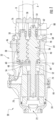
FIG. 1 is a cross-sectional view of a compressor; -
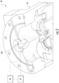
FIG. 2 is a perspective view of a volume index valve of the screw compressor; -
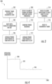
FIG. 3 is a flow diagram illustrating a method of monitoring the volume index valve; and -
FIG. 4 is a plot of an operating condition of the compressor at various positions of the volume index valve against time. - Referring to
FIG. 1 , an example of ascrew compressor 20, commonly used in air conditioning systems, is illustrated in more detail. Thescrew compressor 20 includes ahousing assembly 32 containing amotor 34 and two or more intermeshingscrew rotors 36, 38 having respective central longitudinal axes A and B. In the illustrated embodiment, therotor 36 has a male lobed body 40 extending between afirst end 42 and asecond end 44. The male lobed body 40 is enmeshed with a femalelobed body 46 of the other rotor 38. Thefemale lobed body 46 of the rotor 38 has afirst end 48 and asecond end 50. Eachrotor 36, 38 includesshaft portions second ends female lobed body 46. Theshaft portions housing 32 by one ormore inlet bearings 60, and theshaft portions housing 32 by one ormore outlet bearings 62 for rotation about the associated rotor axis A, B. - In the illustrated embodiment, the
motor 34 and theshaft portion 52 of therotor 36 may be coupled so that themotor 34 drives therotor 36 about axis A. When so driven in an operative first direction, therotor 36 drives the other rotor 38 in an opposite second direction. Thehousing assembly 32 includes arotor housing 64 having an upstream/inlet end face 66 and a downstream/discharge end face 68 essentially coplanar with the rotorsecond ends - The
housing assembly 32 further comprises a motor/inlet housing 70 having a compressor inlet/suction port 72 at an upstream end and having adownstream face 74 mounted to the rotor housing upstream face 66 (e.g., by bolts through both housing pieces). Theassembly 32 further includes an outlet/discharge housing 76 having anupstream face 78 mounted to the rotor housingdownstream face 68 and having an outlet/discharge port 80. The rotor housing 64, the motor/inlet housing 70, andoutlet housing 76 may each be formed as castings subject to further finish machining. The refrigerant vapor enters into the inlet orsuction port 72 with a suction pressure and exits thedischarge port 80 of thecompressor 20 with a discharge pressure. The refrigerant vapor within the compression mechanism of the two ormore rotors 36, 38, between theinlet port 72 and thedischarge port 80 has an intermediate pressure. - Referring now to
FIG. 2 , with continued reference toFIG. 1 , avolume index valve 100 is positioned within therotor housing 64, adjacent to thedischarge end rotors 36, 38. The volume index valve provides a flow path for vapor from an intermediate point of therotors 36, 38 to thedischarge port 80, bypassing the last portion of the compression. Thevalve 100 moves automatically between a closed position and an open position in response to the operating pressure of the refrigerant vapor within thecompressor 20 to control the bypass flow and thus the volume index of thecompressor 20. Thevalve 100 is controlled by an actuator. In some embodiments, the actuator is a solenoid actuator. Proper operation of thevolume index valve 100 enables increased efficiency of thecompressor 20 by actively controlling the fluid flow therethrough. This is particularly beneficial when the compressor is operated at part load, for example. - Referring now to
FIG. 3 , a flow diagram illustrates amethod 200 and system of monitoring operation of the volume index valve in the form of a diagnostic routine. Failure to ensure that thevolume index valve 20 is opening and closing properly results in compressor operation at an efficiency that is lower than otherwise available with proper valve operation. The method and system advantageously provide verification that the volume index valve is opening and closing in a desired manner. - The
method 200 may be initiated manually by an operator in some embodiments. However, in the illustrated embodiment,automatic initiation 202 of the method is provided and based on a periodic timer to cause the method to be performed at a specified time interval. Upon initiation, the method includes waiting for normal and stable operation conditions of the compressor to be met 204 and/or stable operation conditions of the system that the compressor operates within. This may include ensuring that one or more operating modes are present and that stability has been satisfied for a specified period of time. For example, compressor temperature and/or pressure within a specified range over a minimum time period may be required to perform the method. Regarding stable operating conditions of the system that the compressor operates within, an example of a system that the compressor operates within is an air conditioning application. In such embodiments, a refrigerant flow rate, system pressure, system temperature, and system efficiency are examples of operating conditions that may be required to be within a specified range to perform the method. If the stability conditions are not met, the method is aborted. - Subsequent to the conditions for stability being met, detection and recordation of an operating condition of the compressor is made 206 with the volume index valve in a first state that corresponds to a first position. In some embodiments, a plurality of recordings are made over a given time interval with the volume index valve in the first position, with the recordings averaged to provide a single operating condition reading, referred to herein as a first reading. Alternatively, or in combination with averaging the recordings, the first reading may be determined by analysis, trending, filtering, etc. The preceding list is merely illustrative and is not intended to be limiting of analysis techniques that may be employed to determine the first reading. In some embodiments, the first state of the volume index valve corresponds to an energized (i.e., ON) state that provides a closed position of the volume index valve. Once sufficient data is recorded with the volume index valve in the first state (i.e., first position), the volume index valve is switched with a controller 99 (
FIG. 2 ) that is in operative communication with the volume index valve to a second state that corresponds to a second position. As with the first position, one or more readings are detected and recorded 208 with the volume index valve in the second position. In embodiments where a plurality of recordings is made, the recordings are averaged to provide a single compressor operating condition reading, referred to herein as a second reading. In some embodiments, the second state of the volume index valve corresponds to a non-energized (i.e., OFF) state that provides an open position of the volume index valve. Although the method is described being carried out by switching the volume index valve from the first (i.e., closed) position to the second (i.e., open) position, it is to be appreciated that the reverse may be true in some embodiments. - The operating condition of the compressor described above refers to a power reading in some embodiments. In particular, a variable frequency drive power reading of the compressor is taken at the two above-described states/positions of the volume index valve. In other embodiments, the operating current of the compressor may be utilized as the operating condition readings. The readings are obtained with a
processor 98 that is in operative communication with thevolume index valve 20 and thecompressor 20 generally (FIG. 2 ). Theprocessor 98 may be part of thecontroller 99 or a separate module. Although a variable speed compressor is noted above, it is to be appreciated that a fixed speed compressor benefits from the embodiments described herein. - The first and second readings are processed by the
processor 98 and a difference between the two readings is calculated. As shown inFIG. 4 , when the volume index valve is in the first state/position, a first operating condition reading 300 is detected. A step-like falloff of the operating condition is observed in certain areas of the compressor map when the volume index valve is switched to the second state/position, as represented withnumeral 302. In particular, there are overlapping areas or "dead zones" in the operating envelope where running with or without the volume index valve does not result in much difference. The compressor could be either a fixed or variable speed compressor. Due to the availability of power reading in the variable frequency drive, that can be used to perform the volume index valve operational determination. Otherwise, the current reading may be employed for the determination for both variable and fixed speed compressors. - In the second state/position, a second operating condition reading 304 is detected. The method includes utilizing the
processor 98 to determine the difference between the operating condition readings and to compare that difference to a predetermined threshold stored in memory of theprocessor 210. A correctly operating system will produce a measurable difference that exceeds the predetermined threshold. As described above, the operating condition measured is power in some embodiments. If the measured power difference fails to exceed the predetermined threshold, this is indicative of a hardware problem with the volume index valve itself and that it is not opening and closing properly. In the case of current as the measured operating condition, a failure to exceed the predetermined threshold is indicative of an electrical failure of the volume index valve. Additionally, installation or mechanical failure may lead to a failure to exceed the predetermined threshold. - If the predetermined threshold is not exceeded, the method includes initiating an alert 212 that prompts an operator to take a corrective action. As described above, a failure of the volume index valve impacts efficiency, but does not warrant a complete shutdown of the compressor so the system continues to operate while the alert is on 214. The alert is maintained until it is manually reset, thereby ensuring that an operator has addressed the problem. Once manually reset, a timer may be reset 216 to determine when the diagnostic routine is again initiated.
- Advantageously, the method and system described herein provides a form of failure detection of the volume index valve. The volume index valve is primarily responsible for providing efficiency benefits. Therefore, a failed valve would reduce unit efficiency. Without the method and system described herein, a volume index valve failure could go unnoticed and impair operating efficiency.
- The use of the terms "a" and "an" and "the" and similar referents in the context of the present disclosure (especially in the context of the following claims) are to be construed to cover both the singular and the plural, unless otherwise indicated herein or clearly contradicted by context. Further, it should further be noted that the terms "first," "second," and the like herein do not denote any order, quantity, or importance, but rather are used to distinguish one element from another. The modifier "about" used in connection with a quantity is inclusive of the stated value and has the meaning dictated by the context (e.g., it includes the degree of error associated with measurement of the particular quantity).
- While the disclosure has been described in detail in connection with only a limited number of embodiments, it should be readily understood that the disclosure is not limited to such disclosed embodiments. Rather, the disclosure can be modified to incorporate any number of variations, alterations, substitutions or equivalent arrangements not heretofore described, but which are commensurate with the spirit and scope of the disclosure. Additionally, while various embodiments of the disclosure have been described, it is to be understood that aspects of the disclosure may include only some of the described embodiments. Accordingly, the disclosure is not to be seen as limited by the foregoing description, but is only limited by the scope of the appended claims.
- The following clauses recite features of the invention that may or may not currently be claimed, but which may serve as basis for amendment and/or one or more divisional applications.
- 1. A method of monitoring a volume index valve of a compressor comprising:
- recording a first reading of an operating condition of the compressor when the volume index valve is in a first position;
- switching the volume index valve to a second position;
- recording a second reading of the operating condition of the compressor when the volume index valve is in the second position;
- calculating a difference between the first reading and the second reading; and
- comparing the difference to a predetermined threshold difference to determine if the volume index valve is moving between the first position and the second position in a desired manner.
- 2. The method of clause 1, further comprising:
- recording a first plurality of readings of the operating condition when the volume index valve is in the first position;
- averaging the first plurality of readings;
- recording a second plurality of readings of the operating condition when the volume index valve is in the second position; and
- averaging the second plurality of readings, wherein the difference calculated is a difference between the averaged first and second plurality of readings.
- 3. The method of clause 1 or 2, further comprising initiating an alert if the difference does not exceed the predetermined threshold.
- 4. The method of clause 3, further comprising maintaining the alert until the alert is manually reset.
- 5. The method of clause 3 or 4, wherein the compressor continues to operate when the alert is initiated.
- 6. The method of any of the preceding clauses, wherein the operating condition is a variable frequency drive power of the compressor.
- 7. The method of any of clauses 1-5, wherein the operating condition is a measured current of the compressor.
- 8. The method of any of the preceding clauses, further comprising automatically performing the method at a specified time interval.
- 9. The method of any of the preceding clauses, wherein the first position of the volume index valve is an open position and the second position of the volume index valve is a closed position.
- 10. The method of any of clauses 1-8, wherein the first position of the volume index valve is a closed position and the second position of the volume index valve is an open position.
- 11. The method of any of the preceding clauses, wherein the method is performed under stable operating conditions of a system that the compressor operates within.
- 12. A volume index valve diagnostic system comprising:
- a compressor;
- a volume index valve disposed in the compressor, the volume index valve moveable between an open position and a closed position;
- a controller in operative communication with the volume index valve to control whether the volume index valve is in the open position or the closed position; and
- a processing device for receiving data for an operating condition of the compressor when the volume index valve is in the open position and when the volume index valve is in the closed position, the processing device having stored in memory a predetermined threshold of a difference between the operating condition at the open position and the closed position.
- 13. The system of clause 12, wherein the operating condition is a variable frequency drive power of the compressor.
- 14. The system of clause 12, wherein the operating condition is a measured current of the compressor.
- 15. The system of any of clauses 12-14, wherein the processing device is programmed to:
- determine the difference between the operating condition at the open position and the closed position; and
- initiate an alert if the difference is less than the predetermined threshold.
Claims (14)
- A method (200) of monitoring a volume index valve (100) of a screw compressor (20) comprising:recording (206) a first reading (300) of an operating condition of the screw compressor when the volume index valve is in a first state that corresponds to a first position;switching the volume index valve to a second state that corresponds to a second position;recording (208) a second reading (304) of the operating condition of the screw compressor when the volume index valve is in the second state;calculating a difference between the first reading and the second reading; andcomparing (210) the difference to a predetermined threshold difference to determine if the volume index valve is moving between the first position and the second position in a desired manner;the method further comprising:verifying that the volume index valve is opening and closing in the desired manner if the difference exceeds the predetermined threshold;determining that the volume index valve has failed and is not opening and closing in the desired manner such that it is impairing operating efficiency if the difference does not exceed the predetermined threshold;wherein upon initiation of the method, the method comprises waiting for stable operation conditions (204) of the screw compressor to be met and/or stable operation conditions of the system that the screw compressor operates within.
- The method of claim 1, further comprising:recording a first plurality of readings of the operating condition when the volume index valve is in the first position;averaging the first plurality of readings;recording a second plurality of readings of the operating condition when the volume index valve is in the second position; andaveraging the second plurality of readings, wherein the difference calculated is a difference between the averaged first and second plurality of readings.
- The method of claim 1 or 2, further comprising initiating an alert if the difference does not exceed the predetermined threshold.
- The method of claim 3, further comprising maintaining the alert until the alert is manually reset.
- The method of claim 3 or 4, wherein the compressor continues to operate when the alert is initiated.
- The method of any of the preceding claims, wherein the operating condition is a variable frequency drive power of the screw compressor (20).
- The method of any of claims 1-5, wherein the operating condition is a measured current of the screw compressor (20).
- The method of any of the preceding claims, further comprising automatically performing the method at a specified time interval.
- The method of any of the preceding claims, wherein the first position of the volume index valve (100) is an open position and the second position of the volume index valve is a closed position.
- The method of any of claims 1-8, wherein the first position of the volume index valve (100) is a closed position and the second position of the volume index valve is an open position.
- A system comprising:a screw compressor (20);a volume index valve (100) disposed in the screw compressor, the volume index valve moveable between an open position and a closed position; anda volume index valve diagnostic system comprising:a controller (99) in operative communication with the volume index valve to control whether the volume index valve is in the open position or the closed position; anda processing device (98) for receiving data for an operating condition of the screw compressor when the volume index valve is in the open position and when the volume index valve is in the closed position, the processing device having stored in memory a predetermined threshold of a difference between the operating condition at the open position and the closed position,wherein the volume index valve diagnostic system is configured to perform the following steps:
wait for stable operation conditions (204) of the screw compressor to be met and/or stable operation conditions of the system that the screw compressor operates within before initiating detection of the data:determine a difference between the operating condition at the open position and the closed position; andcompare (210) the difference to the predetermined threshold difference to determine if the volume index valve is moving between the open position and the closed position in a desired manner;such that the volume index valve diagnostic system is configured to verify that the volume index valve is opening and closing in the desired manner if the difference exceeds the predetermined threshold;determine that the volume index valve has failed and is not opening and closing in the desired manner such that it is impairing operating efficiency if the difference does not exceed the predetermined threshold. - The system of claim 11, wherein the operating condition is a variable frequency drive power of the compressor (20).
- The system of claim 11, wherein the operating condition is a measured current of the compressor (20).
- The system of any of claims 11-13, wherein the processing device is programmed to:
initiate an alert if the difference is less than the predetermined threshold.
Applications Claiming Priority (3)
| Application Number | Priority Date | Filing Date | Title |
|---|---|---|---|
| US201662369816P | 2016-08-02 | 2016-08-02 | |
| EP17752221.6A EP3494307B1 (en) | 2016-08-02 | 2017-08-01 | Method of monitoring a volume index valve of a compressor and diagnostic system |
| PCT/US2017/044859 WO2018026791A1 (en) | 2016-08-02 | 2017-08-01 | Method of monitoring a volume index valve of a compressor and diagnostic system |
Related Parent Applications (2)
| Application Number | Title | Priority Date | Filing Date |
|---|---|---|---|
| EP17752221.6A Division EP3494307B1 (en) | 2016-08-02 | 2017-08-01 | Method of monitoring a volume index valve of a compressor and diagnostic system |
| EP17752221.6A Division-Into EP3494307B1 (en) | 2016-08-02 | 2017-08-01 | Method of monitoring a volume index valve of a compressor and diagnostic system |
Publications (2)
| Publication Number | Publication Date |
|---|---|
| EP4481201A2 true EP4481201A2 (en) | 2024-12-25 |
| EP4481201A3 EP4481201A3 (en) | 2025-02-26 |
Family
ID=59626684
Family Applications (2)
| Application Number | Title | Priority Date | Filing Date |
|---|---|---|---|
| EP17752221.6A Active EP3494307B1 (en) | 2016-08-02 | 2017-08-01 | Method of monitoring a volume index valve of a compressor and diagnostic system |
| EP24208995.1A Pending EP4481201A3 (en) | 2016-08-02 | 2017-08-01 | Method of monitoring a volume index valve of a compressor and diagnostic system |
Family Applications Before (1)
| Application Number | Title | Priority Date | Filing Date |
|---|---|---|---|
| EP17752221.6A Active EP3494307B1 (en) | 2016-08-02 | 2017-08-01 | Method of monitoring a volume index valve of a compressor and diagnostic system |
Country Status (5)
| Country | Link |
|---|---|
| US (1) | US11460024B2 (en) |
| EP (2) | EP3494307B1 (en) |
| CN (1) | CN109642578B (en) |
| RU (1) | RU2019104011A (en) |
| WO (1) | WO2018026791A1 (en) |
Families Citing this family (2)
| Publication number | Priority date | Publication date | Assignee | Title |
|---|---|---|---|---|
| RU2019104011A (en) * | 2016-08-02 | 2020-09-04 | Кэрриер Корпорейшн | METHOD OF CONTROL AND DIAGNOSTIC SYSTEM FOR RETURN PROPORTIONAL VALVE OF THE COMPRESSOR |
| CN109356854B (en) | 2018-10-19 | 2019-12-27 | 珠海格力电器股份有限公司 | Variable volume compressor operation mode judgment method and equipment, variable volume compressor and air conditioner |
Family Cites Families (32)
| Publication number | Priority date | Publication date | Assignee | Title |
|---|---|---|---|---|
| US3811021A (en) * | 1971-12-30 | 1974-05-14 | Tokai Rika Co Ltd | Automatic reset hydraulic switch |
| US4080110A (en) * | 1976-05-10 | 1978-03-21 | Vilter Manufacturing Corporation | Control system for variable capacity gas compressor |
| US5027608A (en) * | 1990-04-20 | 1991-07-02 | American Standard Inc. | Method and apparatus for determining full load condition in a screw compressor |
| US5362206A (en) * | 1993-07-21 | 1994-11-08 | Automation Associates | Pump control responsive to voltage-current phase angle |
| US5524484A (en) | 1993-12-22 | 1996-06-11 | Westinghouse Electric Corporation | Solenoid operated valve diagnostic system |
| US5784245A (en) | 1996-11-27 | 1998-07-21 | Motorola Inc. | Solenoid driver and method for determining solenoid operational status |
| JP3673375B2 (en) | 1997-09-10 | 2005-07-20 | 株式会社神戸製鋼所 | Screw compressor with slide valve for capacity adjustment |
| US6307376B1 (en) | 1998-12-23 | 2001-10-23 | Eaton Corporation | Fault detection system and method for solenoid controlled actuators of a transmission system |
| IT1318802B1 (en) | 2000-08-31 | 2003-09-10 | Nuovo Pignone Spa | REMOTE DIAGNOSIS SYSTEM OF THE STATE OF WEAR OF THE VALVES INSPIRATION AND DELIVERY OF ALTERNATIVE COMPRESSORS. |
| EP1349677A4 (en) * | 2000-10-23 | 2004-04-07 | James Tyson | Improved sound-based vessel cleaner inspection |
| US6659729B2 (en) * | 2001-02-15 | 2003-12-09 | Mayekawa Mfg. Co., Ltd. | Screw compressor equipment for accommodating low compression ratio and pressure variation and the operation method thereof |
| US6621269B2 (en) | 2001-04-11 | 2003-09-16 | Daimlerchrysler Corporation | System for monitoring solenoid flyback voltage spike |
| JP4123893B2 (en) * | 2002-10-15 | 2008-07-23 | ダイキン工業株式会社 | Screw compressor |
| US6739853B1 (en) * | 2002-12-05 | 2004-05-25 | Carrier Corporation | Compact control mechanism for axial motion control valves in helical screw compressors |
| US7206715B2 (en) * | 2003-12-31 | 2007-04-17 | Cardinal Health 303, Inc. | Empty container detection using container side pressure sensing |
| JP4492320B2 (en) | 2004-11-30 | 2010-06-30 | トヨタ自動車株式会社 | Anomaly detection device |
| JP4483770B2 (en) | 2005-11-18 | 2010-06-16 | 株式会社デンソー | Solenoid valve abnormality diagnosis method |
| US7357019B2 (en) | 2005-11-30 | 2008-04-15 | Gm Global Technology Operations, Inc. | Faulty lifter oil manifold assembly solenoid diagnostic system |
| CN100543483C (en) | 2006-07-05 | 2009-09-23 | 鸿富锦精密工业(深圳)有限公司 | Solenoid tester |
| US7441451B2 (en) | 2007-01-31 | 2008-10-28 | Gm Global Technology Operations, Inc. | Diagnostic methods and systems for active fuel management systems |
| US7908913B2 (en) | 2008-12-18 | 2011-03-22 | GM Global Technology Operations LLC | Solenoid diagnostic systems for cylinder deactivation control |
| US9850902B2 (en) * | 2009-03-26 | 2017-12-26 | Johnson Controls Technology Company | Compressor with a bypass port |
| US8453674B2 (en) | 2010-03-12 | 2013-06-04 | Target Rock Division Of Curtiss-Wright Flow Control Corporation | Valve fault indication and control |
| CN103097734B (en) * | 2010-09-14 | 2016-03-23 | 江森自控科技公司 | Compressor and the method for controlling the volume ratio of compressor |
| US9032750B2 (en) * | 2011-10-18 | 2015-05-19 | Johnson Controls Technology Company | Manual Vi adjustment mechanism for screw compressors |
| EP2597405A1 (en) | 2011-11-25 | 2013-05-29 | Thermo King Container-Denmark A/S | Automated method for pre-trip inspecting a container with a climate control system |
| CN105579709B (en) * | 2013-10-01 | 2018-05-04 | 特灵国际有限公司 | Rotary compressor with variable speed and volume control |
| US10954943B2 (en) * | 2013-12-19 | 2021-03-23 | Carrier Corporation | Compressor comprising a variable volume index valve |
| CN106415145B (en) * | 2014-04-11 | 2019-08-06 | 特灵国际有限公司 | HVAC system and control |
| CN204099200U (en) * | 2014-09-23 | 2015-01-14 | 江森自控空调冷冻设备(无锡)有限公司 | The helical-lobe compressor of adjustable interior volume specific ratio |
| US10677246B2 (en) * | 2016-07-18 | 2020-06-09 | Johnson Controls Technology Company | Variable volume ratio compressor |
| RU2019104011A (en) * | 2016-08-02 | 2020-09-04 | Кэрриер Корпорейшн | METHOD OF CONTROL AND DIAGNOSTIC SYSTEM FOR RETURN PROPORTIONAL VALVE OF THE COMPRESSOR |
-
2017
- 2017-08-01 RU RU2019104011A patent/RU2019104011A/en not_active Application Discontinuation
- 2017-08-01 EP EP17752221.6A patent/EP3494307B1/en active Active
- 2017-08-01 CN CN201780050187.8A patent/CN109642578B/en active Active
- 2017-08-01 EP EP24208995.1A patent/EP4481201A3/en active Pending
- 2017-08-01 WO PCT/US2017/044859 patent/WO2018026791A1/en not_active Ceased
- 2017-08-01 US US16/322,768 patent/US11460024B2/en active Active
Also Published As
| Publication number | Publication date |
|---|---|
| CN109642578A (en) | 2019-04-16 |
| RU2019104011A (en) | 2020-09-04 |
| EP3494307A1 (en) | 2019-06-12 |
| US20210381505A1 (en) | 2021-12-09 |
| CN109642578B (en) | 2022-04-01 |
| EP4481201A3 (en) | 2025-02-26 |
| WO2018026791A1 (en) | 2018-02-08 |
| US11460024B2 (en) | 2022-10-04 |
| EP3494307B1 (en) | 2024-12-04 |
Similar Documents
| Publication | Publication Date | Title |
|---|---|---|
| EP2215365B1 (en) | Control system | |
| JP6454564B2 (en) | Turbo refrigerator | |
| KR100834203B1 (en) | Compressor, Refrigerant Cycle and Method of Controlling Compressor | |
| CN108431522B (en) | Centrifugal compressor with liquid injection | |
| WO2006113780A2 (en) | Modulating proportioning reversing valve | |
| US10954943B2 (en) | Compressor comprising a variable volume index valve | |
| US20090311119A1 (en) | Screw Compressor Capacity Control | |
| JPWO2007083794A1 (en) | Air conditioner | |
| US8979509B2 (en) | Screw compressor having reverse rotation protection | |
| JPH0388989A (en) | Screw compression equipment, rotor temperature control device for screw compression equipment, and operation control equipment for screw compression equipment | |
| EP3494307B1 (en) | Method of monitoring a volume index valve of a compressor and diagnostic system | |
| US10006681B2 (en) | Pulse width modulation with discharge to suction bypass | |
| US11397034B2 (en) | Unloading system for variable speed compressor | |
| EP2095037A1 (en) | Suction modulation valve for refrigerant system with adjustable opening for pulse width modulation control | |
| CN112944614A (en) | Control method of air conditioner and air conditioner | |
| CN113550902A (en) | Unloading control method of screw compressor | |
| JPH05157095A (en) | Centrifugal compressor capacity controller | |
| CN110100137B (en) | Eddy unloading detection system | |
| US12305901B2 (en) | Systems and methods for active compressor control | |
| JPH04353201A (en) | Driving device for compressor | |
| JP2025098490A (en) | Screw compressor and refrigeration cycle device | |
| WO2018146805A1 (en) | Refrigerating device | |
| JPS591357B2 (en) | refrigeration cycle | |
| HK1138351B (en) | Pulse width modulation with discharge to suction bypass | |
| JPH05133629A (en) | Cooling apparatus equipped with scroll type compressor |
Legal Events
| Date | Code | Title | Description |
|---|---|---|---|
| PUAI | Public reference made under article 153(3) epc to a published international application that has entered the european phase |
Free format text: ORIGINAL CODE: 0009012 |
|
| STAA | Information on the status of an ep patent application or granted ep patent |
Free format text: STATUS: THE APPLICATION HAS BEEN PUBLISHED |
|
| AC | Divisional application: reference to earlier application |
Ref document number: 3494307 Country of ref document: EP Kind code of ref document: P |
|
| AK | Designated contracting states |
Kind code of ref document: A2 Designated state(s): AL AT BE BG CH CY CZ DE DK EE ES FI FR GB GR HR HU IE IS IT LI LT LU LV MC MK MT NL NO PL PT RO RS SE SI SK SM TR |
|
| RIN1 | Information on inventor provided before grant (corrected) |
Inventor name: MITRA, BISWAJIT Inventor name: LUDWIG, TYLER JOSEPH |
|
| REG | Reference to a national code |
Ref country code: DE Ref legal event code: R079 Free format text: PREVIOUS MAIN CLASS: F04C0018160000 Ipc: F04C0028120000 |
|
| PUAL | Search report despatched |
Free format text: ORIGINAL CODE: 0009013 |
|
| AK | Designated contracting states |
Kind code of ref document: A3 Designated state(s): AL AT BE BG CH CY CZ DE DK EE ES FI FR GB GR HR HU IE IS IT LI LT LU LV MC MK MT NL NO PL PT RO RS SE SI SK SM TR |
|
| RIC1 | Information provided on ipc code assigned before grant |
Ipc: F04C 18/16 20060101ALI20250120BHEP Ipc: F04C 28/28 20060101ALI20250120BHEP Ipc: F04C 28/12 20060101AFI20250120BHEP |
|
| STAA | Information on the status of an ep patent application or granted ep patent |
Free format text: STATUS: REQUEST FOR EXAMINATION WAS MADE |
|
| 17P | Request for examination filed |
Effective date: 20250818 |
|
| GRAP | Despatch of communication of intention to grant a patent |
Free format text: ORIGINAL CODE: EPIDOSNIGR1 |
|
| STAA | Information on the status of an ep patent application or granted ep patent |
Free format text: STATUS: GRANT OF PATENT IS INTENDED |
|
| INTG | Intention to grant announced |
Effective date: 20260319 |