EP4481155A1 - Raise boring tool with improved cuttings evacuation - Google Patents
Raise boring tool with improved cuttings evacuation Download PDFInfo
- Publication number
- EP4481155A1 EP4481155A1 EP23180643.1A EP23180643A EP4481155A1 EP 4481155 A1 EP4481155 A1 EP 4481155A1 EP 23180643 A EP23180643 A EP 23180643A EP 4481155 A1 EP4481155 A1 EP 4481155A1
- Authority
- EP
- European Patent Office
- Prior art keywords
- cutout
- reamer head
- cutter pocket
- cutter
- mounting plate
- Prior art date
- Legal status (The legal status is an assumption and is not a legal conclusion. Google has not performed a legal analysis and makes no representation as to the accuracy of the status listed.)
- Pending
Links
Images



Classifications
-
- E—FIXED CONSTRUCTIONS
- E21—EARTH OR ROCK DRILLING; MINING
- E21B—EARTH OR ROCK DRILLING; OBTAINING OIL, GAS, WATER, SOLUBLE OR MELTABLE MATERIALS OR A SLURRY OF MINERALS FROM WELLS
- E21B10/00—Drill bits
- E21B10/26—Drill bits with leading portion, i.e. drill bits with a pilot cutter; Drill bits for enlarging the borehole, e.g. reamers
- E21B10/28—Drill bits with leading portion, i.e. drill bits with a pilot cutter; Drill bits for enlarging the borehole, e.g. reamers with non-expansible roller cutters
-
- E—FIXED CONSTRUCTIONS
- E21—EARTH OR ROCK DRILLING; MINING
- E21B—EARTH OR ROCK DRILLING; OBTAINING OIL, GAS, WATER, SOLUBLE OR MELTABLE MATERIALS OR A SLURRY OF MINERALS FROM WELLS
- E21B7/00—Special methods or apparatus for drilling
- E21B7/28—Enlarging drilled holes, e.g. by counterboring
Definitions
- the present invention relates to a raise boring tool, more particular to a reamer head for raise boring operations.
- the reamer head having improved cuttings evacuation.
- Raise boring tools have a reamer head that is used for drilling a raise by reaming a pilot hole to the desired final diameter.
- Reamer heads are usually composed of a number of roller cutters which are arranged in an annular pattern on a body and are rotated at the same time as the reamer head is fed upwardly, thus disintegrating the rock around the pilot hole.
- a drive stem or bull nose is located in the pilot hole.
- the pilot hole can either be drilled at the same time as drilling the raise (in the case of blind boring) or in advance.
- a reamer head having wear pads for improved stability and that can be easily replaced after drilling is disclosed in EP3916194 .
- a problem with the type of reamer head shown in figure 3 of EP3916194 is that cuttings easily get stuck in the cutter pockets beneath the roller cutters. This leads to an increased wear of the inserts on the roller cutters.
- the reamer head for raise boring operations comprises: a reamer body, a plurality of roller cutters connected to the body, each connected to the body using a mounting plate, and an upper drill string connection connected to the body.
- the mounting plate comprises a cutout in the form of a through hole for removal of cuttings from the reamer head.
- the present inventors have realized that this configuration alleviates the problem of having cuttings accumulated beneath the roller cutters.
- the upper drill string connection or nose is the forward end of the raise boring tool, or more particularly the reamer head, when the reamer head is used for drilling.
- the upper drill string connection or nose will also be referred to as the forward end.
- the opposite end of the reamer head will be referred to as the rearward end.
- the upper drill string connection is usually connected to a drill pipe which in turn is connected to a drill rig positioned at the top of the hole to be reamed.
- the drill rig will then, through the drill pipe, transmit a rotational and a pulling force to pull the raise boring tool through a pre-drilled pilot hole to make the hole larger in diameter.
- the upper drill string connection is connected to a pilot bit which drills a raise at the same time as the raise boring tool increases the diameter of the hole.
- the raise boring tool additionally has a lower drill string connection for connection to a drill rig positioned below the raise boring tool. This drill rig will then provide a rotational and a pushing force to push the raise boring tool and pilot bit upwards.
- Cuttings produced during the drilling operation will fall down from the roller cutters towards the rearward end due to gravity. Due to the cutout in the mounting plate the cuttings will not accumulate beneath the roller cutter. Instead the cuttings will pass through the cutout and escape down the drilled hole.
- Accumulation of cuttings beneath the roller cutters may lead to that the wear of the roller cutters and the cutting inserts positioned on the roller cutters is increased.
- the roller cutters may also stop rotating due to the accumulation of cuttings.
- the cutout in the form of a through hole in the mounting plate greatly reduces the wear of the roller cutters and cutting inserts and decreases the risk of the roller cutters stopping to rotate.
- the reamer head comprises a cutter pocket below each respective roller cutter, the cutter pocket having a cutter pocket floor wherein the cutter pocket floor comprises an exit with a lowest point that is positioned level, or up to 30 mm above, a bottom of an entrance of the cutout. More preferably, the lowest point of the exit of the cutter pocket floor is at most 20 mm above the entrance of the cutout and most preferably at most 10 mm above.
- the cutter pocket floor has a longitudinal axle which is generally parallel to a surface of a shell of respective roller cutter. Due to gravity cuttings will generally flow in the direction of the longitudinal axle of the cutter pocket floor. In a direction perpendicular to the longitudinal axle the cutter pocket floor is limited by convex edges.
- the exit is defined as the cross section, perpendicular to the longitudinal axle of the cutter pocket floor, that is located at the rearward end of the cutter pocket floor.
- the exit is thus the part of the cutter pocket floor that is closest to the mounting plate. The lowest point of the exit of the cutter pocket floor is the most rearward point of the exit.
- the entrance of the cutout is the opening of the cutout that is facing the cutter pocket floor.
- the bottom of the entrance is the rearward end of the entrance.
- a bottom of the entrance of the cutout is that the cuttings will then smoothly flow from the cutter pocket floor to the cutout and away from the reamer head. If the lowest point of the exit of the cutter pocket floor is located below the bottom of the entrance of the cutout a step will be formed where cuttings may accumulate.
- the cutter pocket floor has a generally concave shape in a direction perpendicular to the longitudinal direction of the cutter pocket to direct cuttings to the center of the cutout.
- concave means that most of the cutter pocket floor has a concave shape in a direction perpendicular to the longitudinal direction of the cutter pocket floor but some parts may have a flat bottom.
- the central part closest to the longitudinal axle of the cutter pocket floor may have a flat bottom and the areas closer to the convex edges are then convex in shape.
- the technical effect of this embodiment is that the cuttings will flow towards the central part closest to the longitudinal axle of the cutter pocket floor and thus reach the entrance of the cutout at a more central position.
- a width X of the cutout can be decreased and more material can be kept in the mounting plate thus leading to a mounting plate with higher strength.
- the cutter pocket comprises a centrally positioned chute in the area adjoining the mounting plate.
- the chute has a concave shape in a direction perpendicular to the longitudinal direction of the cutter pocket.
- the cuttings will flow towards the longitudinal centre line of the chute and the width X of the cutout can thus be made smaller than the width of the chute.
- the width X of the cutout With a decreased width X of the cutout more material can be kept in the mounting plate thus leading to a mounting plate with higher strength.
- the chute has a flat bottom in a direction perpendicular to the longitudinal direction of the cutter pocket.
- the cutout has a width X that is at least 30 % of a width W of the exit of the cutter pocket floor. More preferably, the width X is at least 40 % of the width W of the exit of the cutter pocket floor. Even more preferably, the width X is at least 50 % of the width W of the exit of the cutter pocket floor. Most preferably, the width X is at least 70 % of the width W of the exit of the cutter pocket floor.
- the cutout has a width X and a height Y and the ratio X/Y is between 1 and 5.
- the ratio X/Y is between 1,3 and 4 and most preferably between 1,5 and 3.
- the cutout is limited by two parallel side walls, a top wall and a bottom wall and a radius R1 between the bottom wall and respective side wall is smaller than a radius R2 between the top wall and respective side wall.
- the bottom of the cutout has a large surface for efficient removal of cuttings while the large radii between the top wall and respective side wall ensures that more material can be kept in the mounting plate thus leading to a mounting plate with higher strength.
- the cutout has a cross-sectional area that is generally rectangular.
- the cutout has a cross-sectional area that is generally trapezoidal.
- the cutout has a cross-sectional area that is generally circular.
- the reamer head comprises exactly two roller cutters.
- This arrangement leads to a well balanced raise boring tool and is cost efficient compared to having more than two roller cutters.
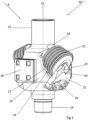
- Fig. 1 shows a raise boring tool 8 having a reamer head 10.
- the reamer head 10 comprises a reamer body 16 with a generally cylindrical shape.
- the cylindrical shape interrupted by cutter pockets 17 wherein roller cutters 21 are rotatably mounted on the reamer body 16 using mounting plates 22 (otherwise known as fasteners, tool holders or saddles).
- the raise boring tool 8 further has an upper drill string connection, or nose, 12 having a threaded connection for attachment to a drill pipe and/or a pilot bit (not shown).
- the upper drill string connection 12 is either connected to a drill pipe which is connected to a drill rig positioned preferably at ground level. The drill rig will then, through the drill pipe, transmit a rotational and a pulling force to pull the raise boring tool 8 through a pre-drilled pilot hole to make the hole larger in diameter.
- the upper drill string connection 12 is connected to a pilot bit which drills a raise at the same time as the raise boring tool increases the diameter of the hole.
- the raise boring tool 8 has a lower drill string connection 14 for connection to a drill rig positioned below the raise boring tool 8. This drill rig will then provide a rotational and a pushing force to push the raise boring tool 8 and pilot bit upwards.
- the raise boring tool 8 has a centre line CL around which the raise boring tool rotates during use.
- Wear pads 28 are attached to the reamer body 16 by conventional attachment means such as, for example, bolting, screwing or welding.
- the wear pads 28 provide stability and wear protection during drilling and are easily replaceable when worn down.
- the roller cutters 21 comprise cutting inserts (not shown).
- the cutting inserts are preferably made of a hard material such as, for example, cemented carbide.
- Roller cutter 21 rotates around an axle 23 which is attached to two saddle seats 24.
- One saddle seat 24 is part of the reamer body 16 and the other saddle seat is part of mounting plate 22.
- Fig. 1 The embodiment shown in Fig. 1 comprises two roller cutters 21. This is the most common number of roller cutters 21 for this type of tool but more than two roller cutters can also be used.
- Mounting plate 22 is preferably attached to the reamer body by conventional attachment means such as, for example, bolting or screwing. Alternatively, the mounting plate 22 can be formed integrally with the reamer body 16. Mounting plate 22 forms an acute angle with the center line CL.
- the mounting plate 22 comprises a cutout 26 in the form of a through hole. If no cutout is present cuttings will be formed during drilling and these cuttings will accumulate in the cutter pocket 17 beneath the roller cutter 21. Accumulation of cuttings in the cutter pocket 17 leads to increased wear of the cutting inserts and an increased load on the bearings in the roller cutter 21. Due to gravity the cuttings will fall downwards, in a direction away from the upper drill string connection 12, and the cuttings can then easily escape the cutter pocket 17 through the cutout 26 and away from the raise boring tool 8.
- Fig. 2 shows the raise boring tool 8 with the roller cutter 21 and mounting plate 22 removed.
- the cutter pocket 17 comprises a cutter pocket floor 18.
- the cutter pocket floor 18 has a generally concave shape in its width direction, i.e. the direction perpendicular to the longitudinal axle of the cutter pocket floor 18. That is a cross section parallel to the width of the mounting plate 22.
- a generally concave shape means that the overall appearance of the cutter pocket floor 18 is concave but that parts of the cutter pocket floor 18 may deviate from a concave shape.
- the central part of the cutter pocket floor 18 has a straight shape.
- the pocket cutter floor 18 is in a direction perpendicular to the longitudinal axle of the pocket cutter floor limited by convex edges 20.
- An exit 19 of the cutter pocket floor is defined as the cross section, perpendicular to the longitudinal axle of the cutter pocket floor 18, that is located at the rearward end of the cutter pocket floor 18.
- the exit 19 is thus the part of the cutter pocket floor 18 that is closest to the mounting plate 22.
- the exit 19 of the cutter pocket floor 18 has a width W.
- Fig. 3 shows a second embodiment of the invention with an alternative design for the cutter pocket 17.
- the cutter pocket floor 18 has an additional chute 18c at the exit 19c of the cutter pocket floor 18.
- the shape of the chute 18c in a cross section perpendicular to the longitudinal axle of the cutter pocket floor 18 is in the shown embodiment generally straight but can in alternative designs have a generally concave shape.
- the width of the exit 19c of the pocket cutter floor 18 is for this embodiment equal to the width of the chute Wc.
- Fig. 4 discloses a cross section through the centre line CL and through the centers of the roller cutters 21.
- the exit 19c of the chute 18c adjoins a bottom of the entrance 27 of the cutout 26.
- the exit 19c is here positioned approximately level with the bottom of the entrance 27 of the cutout 26. In other embodiments the exit 19c may be positioned up to 10 mm above the bottom of the entrance 27 of the cutout 26.
- the entrance of the cutout 26 is the side of the cutout that faces the cutter pocket 17. The reason for having the exit 19c level with, or up to 10 mm above, the bottom of the entrance 27 of the cutout 26 is to decrease the risk of cuttings getting stuck between the chute 18c and the mounting plate 22.
- the exit 19 of the cutter pocket floor 18 is level, or up to 10 mm above, the bottom of the entrance 27 of the cutout 26 in the mounting plate 22.
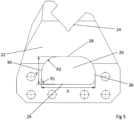
- Fig. 5 shows an embodiment of the mounting plate 22 in a view head-on.
- the cutout 26, in the form of a through hole has a form limited by two parallel side walls 30, a top wall 28 and a bottom wall 29. The respective walls are joined to each other by rounded corners.
- a radius R1 between the bottom 29 and respective side wall 30 is smaller than a radius R2 between the top 28 and respective side wall 30.
- the radius R1 is between 1 mm and 250 mm and the radius R2 is between 2 mm and 300 mm.
- the radii depends on the type of rock that is being drilled and on the size of the raise boring tool 8.
- R1 is smaller than R2.
- the purpose of having a small radius R1 between the bottom 29 and respective side wall 30 is to have as large opening as possible at the bottom of the cutout 26 to efficiently let cuttings through.
- the radius R2 at the top 30 of the cutout 26 is larger to increase the strength of the mounting plate 22 at a part where cuttings are less likely to pass through.
- the cutout 26 has a width X and a height Y.
- the width X is between 50-400 mm and the height Y is between 30-200 mm.
- the ratio between X and Y is between 1 and 5, more preferably between 1,3 and 4 and most preferably between 1,5 and 3. This gives a good balance between strength of the mounting plate 22 and ability for the cutout 26 to let cuttings through.
- the width X of the cutout 26 should preferably be at least 30 % of the width W of the exit 19 of the cutter pocket floor or the exit 19c of the chute.
- the purpose of having a cutout that is at least this wide is to decrease the risk of having cuttings getting stuck between the cutter pocket 17 and the mounting plate 22.
- Fig. 6 shows an alternative embodiment of the cutout 26.
- the cutout 26 here has a rectangular form.
- Fig. 7 shows an alternative embodiment of the cutout 26.
- the cutout 26 here has a trapezoidal shape.
- Fig. 8 shows an alternative embodiment of the cutout 26.
- the cutout 26 here has a circular form.
Landscapes
- Engineering & Computer Science (AREA)
- Geology (AREA)
- Life Sciences & Earth Sciences (AREA)
- Mining & Mineral Resources (AREA)
- Environmental & Geological Engineering (AREA)
- Fluid Mechanics (AREA)
- Physics & Mathematics (AREA)
- General Life Sciences & Earth Sciences (AREA)
- Geochemistry & Mineralogy (AREA)
- Mechanical Engineering (AREA)
- Drilling Tools (AREA)
- Working Measures On Existing Buildindgs (AREA)
- Earth Drilling (AREA)
Abstract
A reamer head 10 for raise boring operations comprising: a reamer body 16, a plurality of roller cutters 21 connected to the body 16, each connected to the body 16 using a mounting plate 22, and an upper drill string connection 12 connected to the body 16, wherein the mounting plate 22 comprises a cutout 26 in the form of a through hole for removal of cuttings from the reamer head 10.
Description
- The present invention relates to a raise boring tool, more particular to a reamer head for raise boring operations. The reamer head having improved cuttings evacuation.
- Raise boring tools have a reamer head that is used for drilling a raise by reaming a pilot hole to the desired final diameter. Reamer heads are usually composed of a number of roller cutters which are arranged in an annular pattern on a body and are rotated at the same time as the reamer head is fed upwardly, thus disintegrating the rock around the pilot hole. During the drilling a drive stem or bull nose is located in the pilot hole. The pilot hole can either be drilled at the same time as drilling the raise (in the case of blind boring) or in advance.
- A reamer head having wear pads for improved stability and that can be easily replaced after drilling is disclosed in
EP3916194 . A problem with the type of reamer head shown infigure 3 ofEP3916194 is that cuttings easily get stuck in the cutter pockets beneath the roller cutters. This leads to an increased wear of the inserts on the roller cutters. - Therefore, there is a need for improvements in reamer heads for raise boring operations such that cuttings are more efficiently transported away from the area beneath the roller cutters.
- It is therefore an object of the present invention to present an improved reamer head for raise boring operations with a decreased risk of having cuttings accumulated beneath the roller cutters.
- According to the present invention, the above mentioned object is achieved by means of a reamer head for raise boring operations having the features defined in claim 1.
- The reamer head for raise boring operations according to the present invention comprises: a reamer body, a plurality of roller cutters connected to the body, each connected to the body using a mounting plate, and an upper drill string connection connected to the body. The mounting plate comprises a cutout in the form of a through hole for removal of cuttings from the reamer head.
- The present inventors have realized that this configuration alleviates the problem of having cuttings accumulated beneath the roller cutters. The upper drill string connection or nose is the forward end of the raise boring tool, or more particularly the reamer head, when the reamer head is used for drilling. In the present application the upper drill string connection or nose will also be referred to as the forward end. The opposite end of the reamer head will be referred to as the rearward end. Throughout the application words like "upper", "top", "above" and "upwards" will be in a direction towards the forward end. Words like "lower", "bottom", "beneath" and "downwards" refer to a direction towards the rearward end.
- The upper drill string connection is usually connected to a drill pipe which in turn is connected to a drill rig positioned at the top of the hole to be reamed. The drill rig will then, through the drill pipe, transmit a rotational and a pulling force to pull the raise boring tool through a pre-drilled pilot hole to make the hole larger in diameter. Alternatively, the upper drill string connection is connected to a pilot bit which drills a raise at the same time as the raise boring tool increases the diameter of the hole. In this case the raise boring tool additionally has a lower drill string connection for connection to a drill rig positioned below the raise boring tool. This drill rig will then provide a rotational and a pushing force to push the raise boring tool and pilot bit upwards.
- Cuttings produced during the drilling operation will fall down from the roller cutters towards the rearward end due to gravity. Due to the cutout in the mounting plate the cuttings will not accumulate beneath the roller cutter. Instead the cuttings will pass through the cutout and escape down the drilled hole.
- Accumulation of cuttings beneath the roller cutters may lead to that the wear of the roller cutters and the cutting inserts positioned on the roller cutters is increased. The roller cutters may also stop rotating due to the accumulation of cuttings. The cutout in the form of a through hole in the mounting plate greatly reduces the wear of the roller cutters and cutting inserts and decreases the risk of the roller cutters stopping to rotate.
- According to one embodiment, the reamer head comprises a cutter pocket below each respective roller cutter, the cutter pocket having a cutter pocket floor wherein the cutter pocket floor comprises an exit with a lowest point that is positioned level, or up to 30 mm above, a bottom of an entrance of the cutout. More preferably, the lowest point of the exit of the cutter pocket floor is at most 20 mm above the entrance of the cutout and most preferably at most 10 mm above.
- The cutter pocket floor has a longitudinal axle which is generally parallel to a surface of a shell of respective roller cutter. Due to gravity cuttings will generally flow in the direction of the longitudinal axle of the cutter pocket floor. In a direction perpendicular to the longitudinal axle the cutter pocket floor is limited by convex edges.
- The exit is defined as the cross section, perpendicular to the longitudinal axle of the cutter pocket floor, that is located at the rearward end of the cutter pocket floor. The exit is thus the part of the cutter pocket floor that is closest to the mounting plate. The lowest point of the exit of the cutter pocket floor is the most rearward point of the exit.
- The entrance of the cutout is the opening of the cutout that is facing the cutter pocket floor. The bottom of the entrance is the rearward end of the entrance.
- The technical effect of having the lowest point of the exit of the cutter pocket floor level, or up to 30 mm above, a bottom of the entrance of the cutout is that the cuttings will then smoothly flow from the cutter pocket floor to the cutout and away from the reamer head. If the lowest point of the exit of the cutter pocket floor is located below the bottom of the entrance of the cutout a step will be formed where cuttings may accumulate.
- According to an embodiment, the cutter pocket floor has a generally concave shape in a direction perpendicular to the longitudinal direction of the cutter pocket to direct cuttings to the center of the cutout.
- Generally concave here means that most of the cutter pocket floor has a concave shape in a direction perpendicular to the longitudinal direction of the cutter pocket floor but some parts may have a flat bottom. The central part closest to the longitudinal axle of the cutter pocket floor may have a flat bottom and the areas closer to the convex edges are then convex in shape.
- The technical effect of this embodiment is that the cuttings will flow towards the central part closest to the longitudinal axle of the cutter pocket floor and thus reach the entrance of the cutout at a more central position. With this arrangement a width X of the cutout can be decreased and more material can be kept in the mounting plate thus leading to a mounting plate with higher strength.
- According to an embodiment, the cutter pocket comprises a centrally positioned chute in the area adjoining the mounting plate.
- From the exit of the cutter pocket floor and upwards along the longitudinal axle of the cutter pocket floor a chute is positioned.
- The technical effect of this embodiment is that most of the cuttings will flow along this chute towards a specific position at the exit of the cutter pocket floor.
- With this arrangement a width X of the cutout can be decreased and more material can be kept in the mounting plate thus leading to a mounting plate with higher strength.
- According to an embodiment, the chute has a concave shape in a direction perpendicular to the longitudinal direction of the cutter pocket.
- With this arrangement the cuttings will flow towards the longitudinal centre line of the chute and the width X of the cutout can thus be made smaller than the width of the chute. With a decreased width X of the cutout more material can be kept in the mounting plate thus leading to a mounting plate with higher strength.
- According to an embodiment, the chute has a flat bottom in a direction perpendicular to the longitudinal direction of the cutter pocket.
- With this arrangement the cuttings will flow evenly along the width of the chute towards the exit of the pocket cutter floor. Since the cuttings will be evenly distributed along the width X of the cutout a height Y of the cutout can be decreased. With a decreased height Y of the cutout more material can be kept in the mounting plate thus leading to a mounting plate with higher strength.
- According to an embodiment, the cutout has a width X that is at least 30 % of a width W of the exit of the cutter pocket floor. More preferably, the width X is at least 40 % of the width W of the exit of the cutter pocket floor. Even more preferably, the width X is at least 50 % of the width W of the exit of the cutter pocket floor. Most preferably, the width X is at least 70 % of the width W of the exit of the cutter pocket floor.
- With this arrangement it is less likely that cuttings accumulate at the edges of the cutout.
- According to an embodiment, the cutout has a width X and a height Y and the ratio X/Y is between 1 and 5.
- More preferably the ratio X/Y is between 1,3 and 4 and most preferably between 1,5 and 3.
- With this arrangement a steady flow of cuttings is achieved while still maintaining sufficient strength in the mounting plate.
- According to an embodiment, the cutout is limited by two parallel side walls, a top wall and a bottom wall and a radius R1 between the bottom wall and respective side wall is smaller than a radius R2 between the top wall and respective side wall.
- With this arrangement the bottom of the cutout has a large surface for efficient removal of cuttings while the large radii between the top wall and respective side wall ensures that more material can be kept in the mounting plate thus leading to a mounting plate with higher strength.
- According to an embodiment, the cutout has a cross-sectional area that is generally rectangular.
- According to an embodiment, the cutout has a cross-sectional area that is generally trapezoidal.
- According to an embodiment, the cutout has a cross-sectional area that is generally circular.
- According to an embodiment, the reamer head comprises exactly two roller cutters.
- This arrangement leads to a well balanced raise boring tool and is cost efficient compared to having more than two roller cutters.
- Further advantages of the present invention will appear from the description following below.
- Embodiments of the invention will now be described in detail with regard to the annexed drawings, in which:
-
Fig. 1 is a perspective view of the reamer head according to a first embodiment of the invention. -
Fig. 2 is a perspective view of the reamer head according to a second embodiment of the invention with the roller cutters and mounting plates removed. -
Fig. 3 is a perspective view of the reamer head according to a first embodiment of the invention with the roller cutters and mounting plates removed. -
Fig. 4 is a cross-sectional view through the center line CL and through the centers of the roller cutters according to the second embodiment of the invention. -
Fig. 5 is a front view of the mounting plate with a first embodiment of the cutout. -
Fig. 6 is a front view of the mounting plate with a second embodiment of the cutout. -
Fig. 7 is a front view of the mounting plate with a third embodiment of the cutout. -
Fig. 8 is a front view of the mounting plate with a fourth embodiment of the cutout. - Reference is made to
Fig. 1 which shows a raiseboring tool 8 having areamer head 10. Thereamer head 10 comprises areamer body 16 with a generally cylindrical shape. The cylindrical shape interrupted bycutter pockets 17 whereinroller cutters 21 are rotatably mounted on thereamer body 16 using mounting plates 22 (otherwise known as fasteners, tool holders or saddles). - The raise
boring tool 8 further has an upper drill string connection, or nose, 12 having a threaded connection for attachment to a drill pipe and/or a pilot bit (not shown). The upperdrill string connection 12 is either connected to a drill pipe which is connected to a drill rig positioned preferably at ground level. The drill rig will then, through the drill pipe, transmit a rotational and a pulling force to pull the raiseboring tool 8 through a pre-drilled pilot hole to make the hole larger in diameter. Alternatively, the upperdrill string connection 12 is connected to a pilot bit which drills a raise at the same time as the raise boring tool increases the diameter of the hole. In this case the raiseboring tool 8 has a lowerdrill string connection 14 for connection to a drill rig positioned below the raiseboring tool 8. This drill rig will then provide a rotational and a pushing force to push the raiseboring tool 8 and pilot bit upwards. - The raise
boring tool 8 has a centre line CL around which the raise boring tool rotates during use. - Wear
pads 28 are attached to thereamer body 16 by conventional attachment means such as, for example, bolting, screwing or welding. Thewear pads 28 provide stability and wear protection during drilling and are easily replaceable when worn down. - The
roller cutters 21 comprise cutting inserts (not shown). The cutting inserts are preferably made of a hard material such as, for example, cemented carbide.Roller cutter 21 rotates around anaxle 23 which is attached to twosaddle seats 24. Onesaddle seat 24 is part of thereamer body 16 and the other saddle seat is part of mountingplate 22. - The embodiment shown in
Fig. 1 comprises tworoller cutters 21. This is the most common number ofroller cutters 21 for this type of tool but more than two roller cutters can also be used. - Mounting
plate 22 is preferably attached to the reamer body by conventional attachment means such as, for example, bolting or screwing. Alternatively, the mountingplate 22 can be formed integrally with thereamer body 16. Mountingplate 22 forms an acute angle with the center line CL. - The mounting
plate 22 comprises acutout 26 in the form of a through hole. If no cutout is present cuttings will be formed during drilling and these cuttings will accumulate in thecutter pocket 17 beneath theroller cutter 21. Accumulation of cuttings in thecutter pocket 17 leads to increased wear of the cutting inserts and an increased load on the bearings in theroller cutter 21. Due to gravity the cuttings will fall downwards, in a direction away from the upperdrill string connection 12, and the cuttings can then easily escape thecutter pocket 17 through thecutout 26 and away from the raiseboring tool 8. -
Fig. 2 shows the raiseboring tool 8 with theroller cutter 21 and mountingplate 22 removed. Thecutter pocket 17 comprises acutter pocket floor 18. Thecutter pocket floor 18 has a generally concave shape in its width direction, i.e. the direction perpendicular to the longitudinal axle of thecutter pocket floor 18. That is a cross section parallel to the width of the mountingplate 22. A generally concave shape means that the overall appearance of thecutter pocket floor 18 is concave but that parts of thecutter pocket floor 18 may deviate from a concave shape. As seen inFig. 2 the central part of thecutter pocket floor 18 has a straight shape. Thepocket cutter floor 18 is in a direction perpendicular to the longitudinal axle of the pocket cutter floor limited byconvex edges 20. - An
exit 19 of the cutter pocket floor is defined as the cross section, perpendicular to the longitudinal axle of thecutter pocket floor 18, that is located at the rearward end of thecutter pocket floor 18. Theexit 19 is thus the part of thecutter pocket floor 18 that is closest to the mountingplate 22. Theexit 19 of thecutter pocket floor 18 has a width W. -
Fig. 3 shows a second embodiment of the invention with an alternative design for thecutter pocket 17. Thecutter pocket floor 18 has anadditional chute 18c at theexit 19c of thecutter pocket floor 18. The shape of thechute 18c in a cross section perpendicular to the longitudinal axle of thecutter pocket floor 18 is in the shown embodiment generally straight but can in alternative designs have a generally concave shape. The width of theexit 19c of thepocket cutter floor 18 is for this embodiment equal to the width of the chute Wc. -
Fig. 4 discloses a cross section through the centre line CL and through the centers of theroller cutters 21. Theexit 19c of thechute 18c adjoins a bottom of theentrance 27 of thecutout 26. Theexit 19c is here positioned approximately level with the bottom of theentrance 27 of thecutout 26. In other embodiments theexit 19c may be positioned up to 10 mm above the bottom of theentrance 27 of thecutout 26. The entrance of thecutout 26 is the side of the cutout that faces thecutter pocket 17. The reason for having theexit 19c level with, or up to 10 mm above, the bottom of theentrance 27 of thecutout 26 is to decrease the risk of cuttings getting stuck between thechute 18c and the mountingplate 22. - On embodiments without a
chute 18c theexit 19 of thecutter pocket floor 18 is level, or up to 10 mm above, the bottom of theentrance 27 of thecutout 26 in the mountingplate 22. -
Fig. 5 shows an embodiment of the mountingplate 22 in a view head-on. Thecutout 26, in the form of a through hole, has a form limited by twoparallel side walls 30, atop wall 28 and abottom wall 29. The respective walls are joined to each other by rounded corners. A radius R1 between the bottom 29 andrespective side wall 30 is smaller than a radius R2 between the top 28 andrespective side wall 30. The radius R1 is between 1 mm and 250 mm and the radius R2 is between 2 mm and 300 mm. The radii depends on the type of rock that is being drilled and on the size of the raiseboring tool 8. Preferably R1 is smaller than R2. - The purpose of having a small radius R1 between the bottom 29 and
respective side wall 30 is to have as large opening as possible at the bottom of thecutout 26 to efficiently let cuttings through. The radius R2 at the top 30 of thecutout 26 is larger to increase the strength of the mountingplate 22 at a part where cuttings are less likely to pass through. - The
cutout 26 has a width X and a height Y. The width X is between 50-400 mm and the height Y is between 30-200 mm. Preferably, the ratio between X and Y is between 1 and 5, more preferably between 1,3 and 4 and most preferably between 1,5 and 3. This gives a good balance between strength of the mountingplate 22 and ability for thecutout 26 to let cuttings through. - The width X of the
cutout 26 should preferably be at least 30 % of the width W of theexit 19 of the cutter pocket floor or theexit 19c of the chute. The purpose of having a cutout that is at least this wide is to decrease the risk of having cuttings getting stuck between thecutter pocket 17 and the mountingplate 22. -
Fig. 6 shows an alternative embodiment of thecutout 26. Thecutout 26 here has a rectangular form. -
Fig. 7 shows an alternative embodiment of thecutout 26. Thecutout 26 here has a trapezoidal shape. -
Fig. 8 shows an alternative embodiment of thecutout 26. Thecutout 26 here has a circular form.
Claims (13)
- A reamer head (10) for raise boring operations, comprising: a reamer body (16); a plurality of roller cutters (21) connected to the body (16), each connected to the body (16) using a mounting plate (22); and an upper drill string connection (12) connected to the body (16);
characterized in that the mounting plate (22) comprises a cutout (26) in the form of a through hole for removal of cuttings from the reamer head (10). - A reamer head (10) according to claim 1, characterized in that the reamer head (10) comprises a cutter pocket (17) below each respective roller cutter (21), the cutter pocket (17) having a cutter pocket floor (18), the cutter pocket floor comprises an exit (19, 19c) with a lowest point that is positioned level, or up to 30 mm above, a bottom of an entrance (27) of the cutout (26).
- A reamer head (10) according to claims 1 or 2, characterized in that the cutter pocket floor (18) has a generally concave shape in a direction perpendicular to the longitudinal direction of the cutter pocket (17) to direct cuttings towards the center of the cutout (26).
- A reamer head (10) according to any of the preceding claims characterized in that the cutter pocket floor (18) comprises a centrally positioned chute (18c) in the area adjoining the mounting plate (22).
- A reamer head (10) according to claim 4, characterized in that the chute (18c) has a concave shape in a direction perpendicular to the longitudinal direction of the cutter pocket (17).
- A reamer head (10) according to any of claims 1 to 4, characterized in that the chute (18c) has a flat bottom in a direction perpendicular to the longitudinal direction of the cutter pocket (17).
- A reamer head (10) according to any of claims 4 to 6, characterized in that the cutout (26) has a width X that is at least 30 % of a width W of the exit of the cutter pocket floor (18).
- A reamer head (10) according to any of the preceding claims, characterized in that the cutout has a width X and a height Y and the ratio X/Y is between 1 and 5.
- A reamer head (10) according to any of the preceding claims, characterized in that the cutout (26) is limited by two parallel side walls (30), a top wall (28) and a bottom wall (29) and a radius R1 between the bottom wall (29) and respective side wall (30) is smaller than a radius R2 between the top wall (28) and respective side wall (30).
- A reamer head (10) according to any of claims 1 to 8, characterized in that the cutout (26a) has a cross-sectional area that is generally rectangular.
- A reamer head (10) according to any of claims 1 to 8, characterized in that the cutout (26b) has a cross-sectional area that is generally trapezoidal.
- A reamer head (10) according to any of claims 1 to 7, characterized in that the cutout (26c) has a cross-sectional area that is generally circular.
- A reamer head (10) according to any of the previous claims, characterized in that the reamer head (10) comprises exactly two roller cutters (21).
Priority Applications (5)
| Application Number | Priority Date | Filing Date | Title |
|---|---|---|---|
| EP23180643.1A EP4481155A1 (en) | 2023-06-21 | 2023-06-21 | Raise boring tool with improved cuttings evacuation |
| PE2025002367A PE20260154A1 (en) | 2023-06-21 | 2024-06-19 | CHIMNEY DRILLING TOOL WITH IMPROVED DEBRIS EVACUATION |
| AU2024313465A AU2024313465A1 (en) | 2023-06-21 | 2024-06-19 | Raise boring tool with improved cuttings evacuation |
| PCT/EP2024/067157 WO2024261092A1 (en) | 2023-06-21 | 2024-06-19 | Raise boring tool with improved cuttings evacuation |
| CN202480033530.8A CN121219480A (en) | 2023-06-21 | 2024-06-19 | Reverse well boring tool with improved chip evacuation |
Applications Claiming Priority (1)
| Application Number | Priority Date | Filing Date | Title |
|---|---|---|---|
| EP23180643.1A EP4481155A1 (en) | 2023-06-21 | 2023-06-21 | Raise boring tool with improved cuttings evacuation |
Publications (1)
| Publication Number | Publication Date |
|---|---|
| EP4481155A1 true EP4481155A1 (en) | 2024-12-25 |
Family
ID=86942711
Family Applications (1)
| Application Number | Title | Priority Date | Filing Date |
|---|---|---|---|
| EP23180643.1A Pending EP4481155A1 (en) | 2023-06-21 | 2023-06-21 | Raise boring tool with improved cuttings evacuation |
Country Status (5)
| Country | Link |
|---|---|
| EP (1) | EP4481155A1 (en) |
| CN (1) | CN121219480A (en) |
| AU (1) | AU2024313465A1 (en) |
| PE (1) | PE20260154A1 (en) |
| WO (1) | WO2024261092A1 (en) |
Citations (5)
| Publication number | Priority date | Publication date | Assignee | Title |
|---|---|---|---|---|
| US2030722A (en) * | 1933-12-01 | 1936-02-11 | Hughes Tool Co | Cutter assembly |
| US2557619A (en) * | 1947-02-15 | 1951-06-19 | Security Engineering Co Inc | Removable pin installation for well drilling cutter assemblies |
| GB2355036A (en) * | 1999-10-08 | 2001-04-11 | Darron Oil Tools Ltd | Cutting Tool |
| US20160305189A1 (en) * | 2013-08-15 | 2016-10-20 | Herrenknecht Ag | Drill head for expanding a pilot bore in order to create a borehole |
| EP3916194A1 (en) | 2020-05-29 | 2021-12-01 | Sandvik Mining and Construction Tools AB | Wear pads for raise boring tools |
-
2023
- 2023-06-21 EP EP23180643.1A patent/EP4481155A1/en active Pending
-
2024
- 2024-06-19 WO PCT/EP2024/067157 patent/WO2024261092A1/en not_active Ceased
- 2024-06-19 AU AU2024313465A patent/AU2024313465A1/en active Pending
- 2024-06-19 CN CN202480033530.8A patent/CN121219480A/en active Pending
- 2024-06-19 PE PE2025002367A patent/PE20260154A1/en unknown
Patent Citations (5)
| Publication number | Priority date | Publication date | Assignee | Title |
|---|---|---|---|---|
| US2030722A (en) * | 1933-12-01 | 1936-02-11 | Hughes Tool Co | Cutter assembly |
| US2557619A (en) * | 1947-02-15 | 1951-06-19 | Security Engineering Co Inc | Removable pin installation for well drilling cutter assemblies |
| GB2355036A (en) * | 1999-10-08 | 2001-04-11 | Darron Oil Tools Ltd | Cutting Tool |
| US20160305189A1 (en) * | 2013-08-15 | 2016-10-20 | Herrenknecht Ag | Drill head for expanding a pilot bore in order to create a borehole |
| EP3916194A1 (en) | 2020-05-29 | 2021-12-01 | Sandvik Mining and Construction Tools AB | Wear pads for raise boring tools |
Also Published As
| Publication number | Publication date |
|---|---|
| WO2024261092A1 (en) | 2024-12-26 |
| PE20260154A1 (en) | 2026-01-23 |
| CN121219480A (en) | 2025-12-26 |
| AU2024313465A1 (en) | 2025-11-13 |
Similar Documents
| Publication | Publication Date | Title |
|---|---|---|
| US8448724B2 (en) | Hole opener with hybrid reaming section | |
| US8191635B2 (en) | Hole opener with hybrid reaming section | |
| US6123161A (en) | Rotary drill bits | |
| US8794356B2 (en) | Shaped cutting elements on drill bits and other earth-boring tools, and methods of forming same | |
| US5553681A (en) | Rotary cone drill bit with angled ramps | |
| US4176723A (en) | Diamond drill bit | |
| EP1815103B1 (en) | Rock drill bit | |
| EP0710765A2 (en) | Improvements relating to rotary drill bits | |
| US5732784A (en) | Cutting means for drag drill bits | |
| EP0117241A1 (en) | Drill bit and improved cutting element | |
| CN102216554A (en) | Drill bit with continuously sharp edge cutting elements | |
| CN112513406B (en) | Downhole tool with fixed cutter for rock removal | |
| US10000973B2 (en) | Reamer for use in drilling operations | |
| EP0974730A2 (en) | Rotary dag bit | |
| CA1095502A (en) | Enhanced cross-flow with two jet drilling | |
| AU2024313465A1 (en) | Raise boring tool with improved cuttings evacuation | |
| EP2486219B1 (en) | Hole opener with hybrid reaming section | |
| EP2486218B1 (en) | Hole opener with hybrid reaming section | |
| CA2776642A1 (en) | Hole opener with hybrid reaming section |
Legal Events
| Date | Code | Title | Description |
|---|---|---|---|
| PUAI | Public reference made under article 153(3) epc to a published international application that has entered the european phase |
Free format text: ORIGINAL CODE: 0009012 |
|
| STAA | Information on the status of an ep patent application or granted ep patent |
Free format text: STATUS: THE APPLICATION HAS BEEN PUBLISHED |
|
| AK | Designated contracting states |
Kind code of ref document: A1 Designated state(s): AL AT BE BG CH CY CZ DE DK EE ES FI FR GB GR HR HU IE IS IT LI LT LU LV MC ME MK MT NL NO PL PT RO RS SE SI SK SM TR |
|
| STAA | Information on the status of an ep patent application or granted ep patent |
Free format text: STATUS: REQUEST FOR EXAMINATION WAS MADE |
|
| 17P | Request for examination filed |
Effective date: 20250625 |