EP4481152A1 - An internal roof window screening arrangement with a connection arm and method for installing such a screening arrangement - Google Patents
An internal roof window screening arrangement with a connection arm and method for installing such a screening arrangement Download PDFInfo
- Publication number
- EP4481152A1 EP4481152A1 EP24182901.9A EP24182901A EP4481152A1 EP 4481152 A1 EP4481152 A1 EP 4481152A1 EP 24182901 A EP24182901 A EP 24182901A EP 4481152 A1 EP4481152 A1 EP 4481152A1
- Authority
- EP
- European Patent Office
- Prior art keywords
- side rail
- screening arrangement
- connection arm
- roof window
- top element
- Prior art date
- Legal status (The legal status is an assumption and is not a legal conclusion. Google has not performed a legal analysis and makes no representation as to the accuracy of the status listed.)
- Pending
Links
Images







Classifications
-
- E—FIXED CONSTRUCTIONS
- E04—BUILDING
- E04D—ROOF COVERINGS; SKY-LIGHTS; GUTTERS; ROOF-WORKING TOOLS
- E04D13/00—Special arrangements or devices in connection with roof coverings; Protection against birds; Roof drainage ; Sky-lights
- E04D13/03—Sky-lights; Domes; Ventilating sky-lights
- E04D13/033—Sky-lights; Domes; Ventilating sky-lights provided with means for controlling the light-transmission or the heat-reflection, (e.g. shields, reflectors, cleaning devices)
-
- E—FIXED CONSTRUCTIONS
- E06—DOORS, WINDOWS, SHUTTERS, OR ROLLER BLINDS IN GENERAL; LADDERS
- E06B—FIXED OR MOVABLE CLOSURES FOR OPENINGS IN BUILDINGS, VEHICLES, FENCES OR LIKE ENCLOSURES IN GENERAL, e.g. DOORS, WINDOWS, BLINDS, GATES
- E06B9/00—Screening or protective devices for wall or similar openings, with or without operating or securing mechanisms; Closures of similar construction
- E06B9/02—Shutters, movable grilles, or other safety closing devices, e.g. against burglary
- E06B9/08—Roll-type closures
- E06B9/11—Roller shutters
- E06B9/17—Parts or details of roller shutters, e.g. suspension devices, shutter boxes, wicket doors, ventilation openings
- E06B9/17061—Connection of the box to the guides
-
- E—FIXED CONSTRUCTIONS
- E06—DOORS, WINDOWS, SHUTTERS, OR ROLLER BLINDS IN GENERAL; LADDERS
- E06B—FIXED OR MOVABLE CLOSURES FOR OPENINGS IN BUILDINGS, VEHICLES, FENCES OR LIKE ENCLOSURES IN GENERAL, e.g. DOORS, WINDOWS, BLINDS, GATES
- E06B9/00—Screening or protective devices for wall or similar openings, with or without operating or securing mechanisms; Closures of similar construction
- E06B9/56—Operating, guiding or securing devices or arrangements for roll-type closures; Spring drums; Tape drums; Counterweighting arrangements therefor
- E06B9/58—Guiding devices
-
- E—FIXED CONSTRUCTIONS
- E06—DOORS, WINDOWS, SHUTTERS, OR ROLLER BLINDS IN GENERAL; LADDERS
- E06B—FIXED OR MOVABLE CLOSURES FOR OPENINGS IN BUILDINGS, VEHICLES, FENCES OR LIKE ENCLOSURES IN GENERAL, e.g. DOORS, WINDOWS, BLINDS, GATES
- E06B9/00—Screening or protective devices for wall or similar openings, with or without operating or securing mechanisms; Closures of similar construction
- E06B9/56—Operating, guiding or securing devices or arrangements for roll-type closures; Spring drums; Tape drums; Counterweighting arrangements therefor
- E06B9/58—Guiding devices
- E06B2009/587—Mounting of guiding devices to supporting structure
-
- E—FIXED CONSTRUCTIONS
- E06—DOORS, WINDOWS, SHUTTERS, OR ROLLER BLINDS IN GENERAL; LADDERS
- E06B—FIXED OR MOVABLE CLOSURES FOR OPENINGS IN BUILDINGS, VEHICLES, FENCES OR LIKE ENCLOSURES IN GENERAL, e.g. DOORS, WINDOWS, BLINDS, GATES
- E06B9/00—Screening or protective devices for wall or similar openings, with or without operating or securing mechanisms; Closures of similar construction
- E06B9/24—Screens or other constructions affording protection against light, especially against sunshine; Similar screens for privacy or appearance; Slat blinds
- E06B9/40—Roller blinds
- E06B9/42—Parts or details of roller blinds, e.g. suspension devices, blind boxes
Definitions
- the present invention relates to an internal roof window screening arrangement for mounting in a roof window, the roof window having a frame structure comprising a top member and a bottom member extending in a width direction and two mutually parallel side members extending in a longitudinal direction, the width direction and longitudinal direction defining a plane, the screening arrangement comprising a top element including a front cover configured to extend in the width direction in a mounted condition of the screening arrangement, and two side rails, wherein the screening arrangement is configured to be brought from a supply condition in which said side rails are detached from the top element to the mounted condition in which the side rails are connected to the top element and to respective side members of the frame structure and extending substantially in said plane.
- the invention also relates to a method for installing such a screening arrangement.
- Such internal screening arrangements provided for screening of windows installed in a roof are typically brought from the supply condition to the mounted condition in which the screening arrangement is connected to the frame structure of the roof window by a user not necessarily possessing craftsperson skills. Since the roof window is by nature provided in an inclined position, generally in a clearing in an inclined inner wall, mounting of such screening arrangements is particularly challenging and requires manual handling of the various components of the screening arrangement at the same time while fitting the components together.
- the screening arrangement further comprises a set of connection arms, each connection arm comprising a first end connected to or connectable to the top element, and each connection arm being further adapted to be connected to the respective side rail at a second end such that a hinge connection is formed between the top element and each side rail, and in that each side rail and at least a part of the respective connection arm when connected to the top element are configured to assume a first position at an angle relative to said plane corresponding to an assembly condition and a second position in which the side rail is parallel to the plane corresponding to the mounted condition, the side rails being allowed to hang free substantially vertically in the assembly condition, and each side rail being configured to be fixed to the frame structure in the second position to obtain the mounted condition in which each side rail extends along a side member of the frame structure.
- connection arms and the intermediate assembly condition of the screening arrangements between the supply condition and the mounted condition, the side rails may be connected and at least temporarily retained to the top element one after the other. This may for instance be the case when the person performing the mounting has mounted one side rail and reaches out for the other side rail, without the need to finalise fixing the first side rail to the side member of the frame structure first.
- the hinge connection allows the side rail is able to form an angle with a plane defined by the front rail of the top element which in the mounted condition of the screening arrangement substantially coincides with the plane defined by the frame such that the side rail assumes a free-hanging configuration.
- each side rail comprises a track
- the side rail is adapted to connect with the connection arm by receiving at least a part of the connection arm in the track. This provides for a mechanically simple and swiftly established connection between the connection arm and the side rail.
- each connection arm and the corresponding side rail are adapted to obtain a locked condition by means of a snap-lock.
- a snap-lock provides a reliable connection between the top element and the side rails.
- the snap-lock may be configured to be released either by a hard pull of the side rail, or require manual unlocking, for instance by moving the snap engagement members relative to each other.
- the snap-lock is configured to allow movement of the side rail in an upwards direction but prevents movement of the side rail in a downwards direction. In this way, the flexibility of installation is improved even further since unavoidable tolerances in the frame structure may be taken into account and accommodated by the movability of the side rail in the longitudinal direction along the side member of the frame structure.
- the snap-lock comprises a flexible tongue arranged on the connection arm configured to interact with the track of the side rail to obtain the locked condition, preferably the flexible tongue and connection arm are integrally formed.
- each connection arm comprises a latch configured to interact with engagement means in the track in the side rail.
- a latch is rigid in itself, and engagement and disengagement, respectively, with counterpart engagement means of the side rail is made possible by the presence of the hinge function of the connection arm.
- the engagement means in the track in the side rail may for instance be formed by an inserted hook element that could in principle also provide for resilient engagement with the latch of the connection arm.
- the hinge connection between the top element and each side rail is formed by providing the connection arm as a flexible element, preferably a resiliently flexible element, more preferably formed as a flexible spring or a strip of elastic material.
- the hinge connection is provided by the connection arm itself.
- the hinge connection may be formed by an actual hinge portion of the connection arm, or solely by the inherent properties of the connection arm. This embodiment has the advantage that the connection arms may be provided as part of the top element during transportation and handling of the screening arrangement with a reduced risk of damaging any components due to the ability of the connection arm to flex.
- connection arm In a preferred further development of this embodiment, the first end of each connection arm is fixedly connected to the top element in the supply condition. This facilitates the mounting procedure further, since it makes the step of connecting the connection arms to the top element during the installation process superfluous.
- each connection arm is provided as a separate element in the supply condition and comprises means for releasable connection with the top element. This provides increased flexibility in the design and manufacture of the connection arm, while still allowing for easy and logical mounting of the screening arrangement.
- the hinge connection between the connection arm and top element is provided by means of a hook adapted to connect to at least one pin.
- a hinge connection is easily obtained and is a well-proven technical solution.
- connection arm may advantageously comprise the hook, and the at least one pin extends from the top element.
- the hook is a two-part hook comprising two hook arms such that a slit is formed between the two hook arms, and the hinge connection comprises two pins projecting in opposite directions from a pin plate, wherein the pin plate is adapted to engage with the slit and each hook arm is adapted to engage with one of the two pins.
- the symmetry also provides for improved load-transferring properties.
- the at least one pin has an elongated cross-section with a pin width and a pin length
- the hook has a hook opening with a hook opening width, wherein the hook opening width is shorter than the pin length and larger than the pin width.
- the screening arrangement further comprises a spring assembly configured to provide a bias on the respective side rail in the longitudinal direction, preferably via the connection arm or on the bottom member of the frame structure in the mounted condition.
- the spring assembly comprises a spring which is compressible in the longitudinal direction and a sledge slidable in a track of the side rail, the spring being positioned to exert a force on the sledge, and wherein the sledge and the track comprise complementary locking means to retain the spring in a compressed state.
- the bias of the spring assembly may be prepared in a separate step during installation and remain biased until the user releases the complementary locking means at a suitable time. Without such complementary locking means, the biasing effect would still be obtainable, but the user would have to overcome the spring force throughout the mounting.
- the spring of the spring assembly may be configured to abut the second end of the connection arm in the assembly condition and in the mounted condition, and wherein the sledge is configured to be manually movable between a first opening and a second opening in the track of the side rail, the spring being in a compressed state when positioned in the second opening.
- each side rail is adapted to be mounted on a side member of the frame structure by means of at least one connection part to obtain a mounted condition, each connection part being mounted on the side member by means of an adhesive portion. In this way, it is ensured that the risk of damage to the roof window itself is minimised.
- the roof window remains substantially intact.
- each connection part further comprises engagement means adapted to engage with the side rail to obtain the mounted condition, said engagement means preferably comprising an engagement tongue of a tab connected to a central portion of the connection part, the tab being preferably connected to the central portion of the connection part by means of a resilient suspension ring, said engagement means being more preferably adapted to engage with a track of the side rail such that the side rail is freely slidable in the length direction when engaged with the connection part.
- the top element comprises two end pieces at respective longitudinal ends of the top element, and the top element is mounted to the frame structure by means of the end pieces engaging with mounting brackets provided on side members of the frame structure in a snap engagement.
- mounting brackets are well-known in the art and are typically pre-mounted in commercially available roof windows or may be supplied together with the screening arrangement of the invention as an installation kit for mounting in a step preceding the mounting of the screening arrangement itself.
- a method for installing an internal roof window screening arrangement comprises the steps of;
- the subsequent fixing of the side rails to the frame structure is typically carried out by attaching the side rails to the associated side member of the frame in question, most often the sash of the roof window, but other attachment locations are conceivable. It is preferred that a separate connection part with an adhesive portion fastened to the respective side members be used.
- the mounting of the top element may also be carried out arbitrarily; however, the use of mounting brackets on the side members is preferred for interaction with appropriately formed end pieces at the longitudinal ends of the top element.
- a feature described in relation to one of the aspects may also be incorporated in the other aspect, and the advantage of the feature is applicable to all aspects in which it is incorporated.
- a schematic drawing of a roof window 1 is shown from an internal, or interior, side.
- the roof window comprises one or more frame structures, typically a stationary frame 3 and a sash 2 carrying a glazing element 4 such as a transparent pane.
- the sash 2 may be openable or fixed.
- Fig. 1 shows an embodiment of a roof window 1 comprising a stationary frame 3 and an openable sash 2.
- the frame structure of the roof window will in the following be represented by the sash 2 which comprises two side members 2.2 and 2.3 extending in a height direction, here denoted a longitudinal direction L.
- the sash 2 further comprises a top member 2.1 and a bottom member 2.4 extending in a width direction W.
- the width direction Wand length direction L define a plane P (indicated in Fig. 9 ), to which a depth direction D is perpendicular.
- a window opening 5 is thus formed, here defined by the inner sides of the sash members 2.1, 2.2, 2.3, 2.4, and which window opening 5 is to be screened by a roof window screening arrangement 10 according to the invention as will be described in further detail below.
- the screening arrangement 10 may be arranged in the stationary frame 3, such as between two side members of the stationary frame 3.
- the roof window 1 is adapted to be installed in an inclined roof, here by means of a set of frame mounting brackets connected to the stationary frame 3 and of which two representative frame mounting brackets 6 are shown. It is noted that the inclinations shown throughout the drawings are merely representations and that an internal roof window screening arrangement 10 according to the invention may be mounted in a roof window 1 with an inclination different from the one indicated in these embodiments.
- the roof window screening arrangement 10 is shown in a mounted condition in the roof window 1.
- the screening arrangement 10 comprises two side rails 12, 13 connected to respective sash side members 2.2, 2.3.
- the side rail 13 is here a mirror version of side rail 12 and the two side rails 12, 13 are mounted in the same manner.
- detailed reference only to the right-hand side rail 12 will be made; it is to be understood that any features relating to the side rail 12 apply to the opposite side rail 13 as well.
- the two side rails 12, 13 each extends by its length extension in the longitudinal direction L in the mounted condition of the screening arrangement 10, and as shown for side rail 12, it has a side rail front 12.2 having a width dimension extending in the width direction W in the mounted condition.
- the side rail 12 has a track 12.1 having an extension in the depth direction D from the side rail front 12.2 and extending in the longitudinal direction L in the mounted condition of the screening arrangement 10 as shown in Fig. 1 .
- the screening arrangement additionally comprises a top element 11 extending between the two side members 2.2 and 2.3 in the mounted condition of the screening arrangement 10, in proximity of the top member 2.1 as shown in Fig. 1A .
- the top element 11 comprises a front cover 11.1 and may further comprise a back cover 11.2 and two end pieces 11.3, 11.4, with one end piece arranged at each end of the top element 11 as is known in the art.
- the front cover 11.1 of the top element 11 of the screening arrangement 10 has a generally elongate shape and extends in the width direction W, which is the same as the lengthwise direction of the front cover 11.1.
- the front cover 11.1 defines a plane as indicated in Fig.
- each side rail 12, 13 When referring to the side rails 12, 13 being in the mounted condition, i.e. in a position in which each side rail 12, 13 is substantially parallel to the plane P, it is to be understood as the side rail 12 being connected to the side member 2.2 of the sash 2 and the side rail 13 to the other side member 2.3.
- the side rail 12 is connected to the side member 2.2 partly via the top element 11, partly by means of a connection part 20 provided with an adhesive portion 21 on a surface facing the side member of the frame structure in the mounted condition.
- Fig. 2 shows a connection part 20 mounted on the left-hand sash side member 2.3.
- the connection part 20 is intended to provide the connection of the side rail 13 to the side member 2.3 of the sash 2 in the mounted condition of the screening arrangement 10.
- a corresponding connection part 20 is just visible on the right-hand sash side member 2.2 to provide connection of the side rail 12.
- each connection part 20 comprises engagement means 22 adapted to engage with the respective side rail 12, 13 to obtain the mounted condition.
- the engagement means 22 may as shown in Fig. 1C comprise an engagement tongue of a tab connected to a central portion of the connection part 20.
- the tab is preferably connected to the central portion of the connection part 20 by means of a resilient suspension ring.
- the engagement means 22 are adapted to engage with the track 12.1 of the side rail 12 such that the side rail 12 is freely slidable in the length direction when engaged with the connection part 20.
- connection of the side rails 12, 13 to the top element 11 by means of a respective connection arm 7 allowing the side rails to rotate by means of a hinge connection with the top element 11 will be described in further detail below.
- the screening arrangement 10 additionally comprises a screening body 15 having two side edges and a predefined length between a first end portion and a second end portion.
- the screening body 15 is movable in the longitudinal direction L between a non-screening position and a screening position in which the screening body 15 substantially covers the glazing element 4. In the non-screening position, the screening body 15 is configured to be accommodated in the top element 11 as shown in Fig. 2 .
- Fig. 1 the window opening 5 covered by the glazing element 4 is in turn covered by the screening body 15.
- a bottom profile 14 is provided to extend substantially in parallel with the top element 11 and is connected to the second end portion of the screening body 15.
- Fig. 1B shows a detailed view of the bottom profile 14 with two guide elements 14.1 and 14.2 of the bottom profile 14 engaging with the side rails 12, 13. By means of the guide elements 14.1 and 14.2, side edges of the screening body 15 and ends of the bottom profile 14 are guided on a back side of the side rails 12, 13 during screening.
- an end stop 14.3 is provided towards the bottom end of each side rail 12, 13 as shown in Fig. 1C , for instance fastened to the bottom member 2.4 of the sash 2.
- FIG. 1A the roof window screening arrangement 10 is shown in a mounted condition.
- a mounted condition of the top element 11 refers to the top element 11 being fixed in the frame structure, such as the sash 2, here to the side members 2.2, 2.3 by suitable attachment means such as mounting brackets 24 pre-mounted at the top of each side member 2.2, 2.3 of the sash 2 ( Fig. 14D ).
- the top element 11 may alternatively and/or additionally be fixed to the top member 2.1 of the sash 2, or other frame structure.
- connection arms 7 may either be pre-connected to the top element 11, or be supplied separately and connected to the top element 11 during installation in preparation of the step of connecting the side rails 12, 13.
- the connection arms 7 are connected to side rails 12, 13 such that a hinge connection is formed between the top element 11 and each side rail 12, 13.
- FIG. 2 shows the screening arrangement 10 at one step during the mounting procedure, the top element 11 being already in the position it will assume in the mounted condition of the screening arrangement 10 while the side rails 12, 13 are connected to the top element 11 by means of respective connection arms 7 and assume a first position corresponding to an assembly condition of the screening arrangement 10.
- the side rails 12, 13 and at least a part of the respective connection arm 7 form an angle ⁇ relative to the plane P. Since internal roof window screening arrangements of the present invention are mounted in roof windows installed in roofs having an inclination with the vertical, gravity will act to swing the side rails 12, 13 towards a substantially vertical position, the side rails 12, 13 being thus allowed to hang free in the assembly condition.
- the side rails 12, 13 are rotated through the angle ⁇ and into a second position in which the side rails 12, 13 are located substantially in parallel with the plane P and extend along respective side members 2.2, 2.3, following which they are connected to the sash 2, or other frame structure, in any suitable manner, here as mentioned in the above by means of the connection parts 20 fastened to the side members 2.2 or 2.3 of the sash 2.
- the hinge connection between the top element 11 and the side rails 12, 13 allows at least temporary retention of the side rails 12, 13 on the respective connection arm 7.
- connection arm 7 with the shape of a substantially longitudinal element, comprising a body portion with two ends, namely a first end 7.1 connected to or connectable to the top element 11, and a second end 7.2 to engage and retain the side rail 12, for instance in the track 12.1.
- connection arm 7 and the side rail 12, 13 are adapted to obtain a locked condition by means of a snap-lock.
- the snap-lock of the embodiments shown is configured to allow movement of the side rail 12, 13 in an upwards direction but prevents movement of the side rail 12, 13 in a downwards direction.
- the engagement between the second end 7.2 of the connection arm 7 and the side rail 12 may be frictional.
- FIG. 3A , 3B , and 3C show three alternative embodiments of the connection arm 7.
- elements having the same or analogous function are denoted by the same reference numerals. Only differences will be described in detail.
- connection arm 7 is formed as a flexible element allowing the second end 7.2 of the connection arm 7 to engage and follow the side rail 12 while the first end 7.1 remains stationary relative to the top element 11.
- the flexibility is obtained by providing a hinge 7.5 between the first and second ends 7.1 and 7.2.
- the connection arm 7 is a resiliently flexible element formed as a strip of elastic material.
- the connection arm 7 could comprise a spring.
- a latch 7.6 is formed which is configured to be received in the track 12.1 of the side rail 12, together with at least a part of the connection arm 7.
- the latch 7.6 is in itself rigid, and engagement with counterpart engagement means of the side rail is made possible by the hinge functionality provided by the connection arm 7, or by forming the engagement means of the side rail 12 as a flexible and/or elastic engagement means.
- the engagement means (not shown) of the side rail 12 are formed accordingly. In both of these embodiments, it is possible to connect the first end 7.1 of each connection arm 7 fixedly to the top element 11 in the supply condition of the screening arrangement 10.
- connection arm 7 is a substantially rigid longitudinal element. Since the connection arm 7 is rigid, i.e. is able to flex only to a limited extent, the hinge function needs to be provided by a rotational point.
- connection arm 7 of the third embodiment could in principle also be connected to the top element 11 in the supply condition
- connection arm 7 of this embodiment is able to be provided as a separate element in the supply condition and, to this end, the connection arm 7 comprises means for releasable connection with the top element 11.
- the hinge connection between the connection arm 7 and top element 11 is in these embodiments provided by means of a hook 7.3 adapted to be connected to at least one pin 11.3ii.
- the hook 7.3 is here comprised in the connection arm 7 and two pins 11.3ii are comprised in the top element 11.
- the hook 7.3 and connection arm 7 are integrally formed.
- one or more pins could be comprised in the connection arm 7 and the hook in the top element 11.
- the hook 7.3 is here a two-part hook comprising two hook arms 7.3i such that a slit 7.3ii is formed between the two hook arms 7.3i.
- the hinge connection means comprises two pins 11.3ii projecting in opposite directions from a pin plate 11.3i.
- Each hook arm 7.3i is adapted to engage with a respective pin 11.3ii on the pin plate 11.3i.
- This provides a more stable connection, where each of the two hook arms 7.3i engages with one of the two pins 11.3ii projecting from the pin plate 11.3i such that the slit 7.3ii is arranged between the two hook arms 7.3i in a connected condition.
- This arrangement limits unintentional disconnection between the connection arm 7 and the top element 11 such as a twist of the connection arm 7 in a direction different from the intended hinge bend direction.
- Each pin 11.3ii may have an elongated cross-section with a pin width PW and a pin length PL, wherein PL>PW.
- the hook 7.3 may have a hook opening 7.3ii with a hook opening width HOW, wherein the hook opening width is shorter than the pin length, PL>HOW, and the hook opening width is larger than the pin width, PW ⁇ HOW.
- HOW is measured at the outer periphery of the hook 7.3 and the narrowest part of the hook opening 7.3ii is smaller than the HOW.
- the narrowest part of the hook opening 7.3ii is narrower than the PW.
- the HOW is wider than the narrowest part of the hook opening 7.3ii.
- connection arm 7 and the top element 11 are adapted to be connected in a limited number of ways which ensures a correct assembly of the two parts. Additionally, it limits the risk of unintentional disconnection between the two parts once they are assembled.
- Fig. 8B the HOW is aligned with the PW and may thereby be disconnected.
- PL extends in the length direction parallel to the plane and the PW is arranged substantially perpendicular to the plane. In the shown embodiments, this ensures that the hook 7.3 and pin 11.3ii may only connect and disconnect when a length direction of the connection arm 7 is arranged perpendicular to the plane.
- Fig. 8C the connection arm 7 is turned such that the HOW is aligned with the PL. The connection arm 7 and top element 11 are thereby arranged in a locked condition where these cannot disengage without the use of destructive force.
- the track 12.1 of the side rail 12 comprises two track members 12.1i extending perpendicularly from the side rail front 12.2 to form the track 12.1. Additionally, the track 12.1 comprises two track retainers 12.1ii extending from the track members 12.1i substantially in parallel with the side rail front 12.2, such that when the connection arm 7 is inserted in the track 12.1, the connection arm 7 is limited to a sliding movement in the length direction L.
- the track retainers 12.1ii are discontinued intermittently to form one or more openings.
- a first opening 12.4 is provided near the upper end of the side rail 12 and a second opening 12.6 further downwards in the longitudinal direction L.
- the first and second openings 12.4 and 12.6 fulfil a function when the connection arm 7 and side rail 12 are configured to obtain a locked condition by means of a snap-lock.
- the connection arm 7 is adapted to fit in the track 12.1 of the side rail 12 by insertion of the second end 7.2 in one end of the track 12.1. It is noted that the size relation between the drawings figures does not necessarily reflect the size relation of the actual connection arm 7 and side rail 12, and the connection arm 7 is thus dimensioned to fit in the track 12.1 of the side rail 12.
- the snap-lock between the connection arm 7 and the side rail 12 comprises a flexible tongue 7.4 arranged on the connection arm 7 configured to interact with the first opening 12. 4 of the track 12.1 of the side rail 12.
- the locked condition is here obtained in that the flexible tongue 7.4 is pressed inwards during the passage under the track retainers 12.1ii and allowed to resume a relaxed state in the first opening 12.4 and thereby enter the locked condition shown in Fig. 6 .
- the flexible tongue 7.4 is pushed and guided under the track retainers 12.1ii.
- the second opening 12.6 has a function in embodiments in which a spring assembly is included in the screening arrangement 10. Such embodiments are shown in Figs. 10 to 13 .
- a spring assembly 50 is provided which is configured to provide a bias on the side rail 12, 13 in the longitudinal direction L in the mounted condition of the screening arrangement 10.
- the spring assembly 50 interacts with the connection arm 7 to provide the bias.
- biasing means could be provided at the bottom member 2.4 of the sash 2.
- the spring assembly 50 comprises a spring 51 which is compressible in the longitudinal direction and a sledge 52 slidable in the track 12.1 of the side rail 12.
- the spring 51 is positioned to exert a force on the sledge 52, and the sledge 52 and the track 12.1 comprise complementary locking means to retain the spring 51 in a compressed state.
- the sledge 52 comprises a first engagement part 52.1 configured to interact with the second end 7.2 of the connection arm 7, a second engagement part 52.2 interacting the spring 51, and a sledge runner 52.3 interacting with the track 12.1 of the side rail 12.
- a flexible tongue 53 and a finger grip section 54 are provided.
- the spring 51 of the spring assembly 50 in the embodiment shown is configured to abut the second end 7.2 of the connection arm 7 in the assembly condition and in the mounted condition.
- a track plate 12.5 retains the spring 51 relative to the track 12.1 of the side rail 12.
- the sledge 52 is configured to be manually movable between the first opening 12.4 and the second opening 12.6 in the track 12.1 of the side rail 12, in that the spring 51 is in a compressed state when positioned in the second opening 12.6.
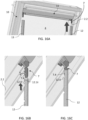
- connection arms 7 are connected to the top casing 11 and if required brought to a suitable position to allow connection with the side rails 12, 13. This is reflected in Figs. 14A to 14C .
- the top casing 11 with attached connection arms 7 is connected to the sash 2 by inserting the end pieces 11.3, 11.4 over mounting brackets 24 at the side members 2.2, 2.3 of the sash as indicated in Fig. 14D .
- the spring assembly 50 is biased by moving the sledge 52 by gripping the finger grip section 54, from the first opening 12.4 to the second opening 12.6 as shown in Figs. 15A and 15B .
- the side rails 12, 13 are then connected to the respective connection arm 7 and thus to the top element 11 as indicated in Figs. 16A to 16C .
- the screening arrangement 10 When the screening arrangement 10 is installed in roof window 1 in a roof with an inclination, the screening arrangement 10 will itself be inclined relative to the ground.
- the side rails 12, 13 are hingedly connected to the top element 11 and are allowed to hang free in the assembly position, the side rails 12, 13 will become substantially vertically arranged due to the pull of gravity.
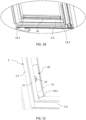
- Fig. 17A it is shown how the person performing the mounting takes hold of the side rail 12 and rotates it out of the vertical position in the direction towards the exterior until the side rail 12 is parallel to the plane P and the engagement means 22 of the connection part 20 is guided into the track 12.1 of the side rail.
- the upper edge of the side rail 12 is arranged behind the front cover 11.1 of the top element 11 as shown in the enlarged cut-out of Fig. 17B .
- Alternative configurations include that the front cover 11.1 of the top element and side rail front 12.2 are arranged to form a uniform front towards the interior such as a mitre joint.
- the side rails 12, 13 may as shown be mounted independently of each other, that is, one side rail may be connected to the connection arm 7 and then rotated into position and fixed in its mounted position while the other side rail is still in its supply condition. Or, as in the embodiments described, both side rails 12, 13 are connected to respective connection arms 7 and allowed to hang free before rotating one after the other into position. A further alternative is to take hold of both side rails 12, 13 at the same time from their free-hanging position and then rotate into place.
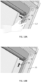
- Figs. 18A and 18B show how the spring 51 of the spring assembly 50 is allowed to exert its bias by moving the sledge 52 by its finger grip section 54 such that the side rail 12 is pressed downwards, thus providing a compression mount.
Landscapes
- Engineering & Computer Science (AREA)
- Structural Engineering (AREA)
- Architecture (AREA)
- Civil Engineering (AREA)
- Wing Frames And Configurations (AREA)
- Curtains And Furnishings For Windows Or Doors (AREA)
Abstract
In the internal roof window screening arrangement (10), a set of connection arms (7) is provided, each connection arm (7) comprising a first end connected to or connectable to the top element (11) and adapted to be connected to the respective side rail (12, 13) at a second end such that a hinge connection is formed between the top element (11) and each side rail (12, 13). Each side rail (12, 13) and at least a part of the respective connection arm (7) when connected to the top element (11) are configured to assume a first position at an angle (α) relative to a plane (P) of a front cover (11.1) of the top element (11) corresponding to an assembly condition and a second position in which the side rail (12, 13) is parallel to the plane (P) corresponding to the mounted condition, the side rails (12, 13) being allowed to hang free substantially vertically in the assembly condition, and each side rail (12, 13) being configured to be fixed to the frame structure (2) in the second position to obtain the mounted condition in which each side rail (11, 12) extends along a side member (2.2, 2.3) of frame structure (2).
Description
- The present invention relates to an internal roof window screening arrangement for mounting in a roof window, the roof window having a frame structure comprising a top member and a bottom member extending in a width direction and two mutually parallel side members extending in a longitudinal direction, the width direction and longitudinal direction defining a plane, the screening arrangement comprising a top element including a front cover configured to extend in the width direction in a mounted condition of the screening arrangement, and two side rails, wherein the screening arrangement is configured to be brought from a supply condition in which said side rails are detached from the top element to the mounted condition in which the side rails are connected to the top element and to respective side members of the frame structure and extending substantially in said plane. The invention also relates to a method for installing such a screening arrangement.
- Such internal screening arrangements provided for screening of windows installed in a roof are typically brought from the supply condition to the mounted condition in which the screening arrangement is connected to the frame structure of the roof window by a user not necessarily possessing craftsperson skills. Since the roof window is by nature provided in an inclined position, generally in a clearing in an inclined inner wall, mounting of such screening arrangements is particularly challenging and requires manual handling of the various components of the screening arrangement at the same time while fitting the components together.
- Prior art document
WO2008/131759 A1 shows and describes one example of an internal roof window screening arrangement of the kind mentioned in the introduction. While this document provides for relatively easy mounting, there is always room for improvement. - With this background, it is therefore an object of the invention to provide a screening arrangement by which a facilitated and flexible installation is made possible.
- In a first aspect, this and further objects are achieved with a roof window of the kind mentioned in the introduction which is furthermore characterised in that the screening arrangement further comprises a set of connection arms, each connection arm comprising a first end connected to or connectable to the top element, and each connection arm being further adapted to be connected to the respective side rail at a second end such that a hinge connection is formed between the top element and each side rail, and in that each side rail and at least a part of the respective connection arm when connected to the top element are configured to assume a first position at an angle relative to said plane corresponding to an assembly condition and a second position in which the side rail is parallel to the plane corresponding to the mounted condition, the side rails being allowed to hang free substantially vertically in the assembly condition, and each side rail being configured to be fixed to the frame structure in the second position to obtain the mounted condition in which each side rail extends along a side member of the frame structure.
- By the provision of the connection arms and the intermediate assembly condition of the screening arrangements, between the supply condition and the mounted condition, the side rails may be connected and at least temporarily retained to the top element one after the other. This may for instance be the case when the person performing the mounting has mounted one side rail and reaches out for the other side rail, without the need to finalise fixing the first side rail to the side member of the frame structure first. The hinge connection allows the side rail is able to form an angle with a plane defined by the front rail of the top element which in the mounted condition of the screening arrangement substantially coincides with the plane defined by the frame such that the side rail assumes a free-hanging configuration. Once the side rail or both side rails have been connected to respective connection arms, the user will be able to rotate the side rail by means of the hinge connection into the intended position along the side member of the frame structure and only then finalise the mounting procedure to obtain the mounted condition in which each side rail extends along a side member of the frame structure.
- In a presently preferred embodiment, each side rail comprises a track, and the side rail is adapted to connect with the connection arm by receiving at least a part of the connection arm in the track. This provides for a mechanically simple and swiftly established connection between the connection arm and the side rail.
- While it may in principle be sufficient to provide only a temporary retention of the side rail, for instance by an interference fit with the connection arm that is relatively easily overcome by overriding the frictional forces, it is advantageous if each connection arm and the corresponding side rail are adapted to obtain a locked condition by means of a snap-lock. Such a snap-lock provides a reliable connection between the top element and the side rails. The snap-lock may be configured to be released either by a hard pull of the side rail, or require manual unlocking, for instance by moving the snap engagement members relative to each other.
- In a preferred further development of this embodiment, the snap-lock is configured to allow movement of the side rail in an upwards direction but prevents movement of the side rail in a downwards direction. In this way, the flexibility of installation is improved even further since unavoidable tolerances in the frame structure may be taken into account and accommodated by the movability of the side rail in the longitudinal direction along the side member of the frame structure.
- In a presently preferred embodiment incorporating such a snap-lock, the snap-lock comprises a flexible tongue arranged on the connection arm configured to interact with the track of the side rail to obtain the locked condition, preferably the flexible tongue and connection arm are integrally formed. Providing the active part of the snap engagement means on the connection arm itself allows the side rails to be manufactured as a more or less standard version of for instance an extruded profile of a metal or composite material, while the connection arm may be formed by moulding to include the flexible tongue.
- In another embodiment, the at least temporary retention between the side rail and the connection arm and, in turn, the top element, is provided in that each connection arm comprises a latch configured to interact with engagement means in the track in the side rail. Such a latch is rigid in itself, and engagement and disengagement, respectively, with counterpart engagement means of the side rail is made possible by the presence of the hinge function of the connection arm. The engagement means in the track in the side rail may for instance be formed by an inserted hook element that could in principle also provide for resilient engagement with the latch of the connection arm.
- In one embodiment, the hinge connection between the top element and each side rail is formed by providing the connection arm as a flexible element, preferably a resiliently flexible element, more preferably formed as a flexible spring or a strip of elastic material. In this way, the hinge connection is provided by the connection arm itself. The hinge connection may be formed by an actual hinge portion of the connection arm, or solely by the inherent properties of the connection arm. This embodiment has the advantage that the connection arms may be provided as part of the top element during transportation and handling of the screening arrangement with a reduced risk of damaging any components due to the ability of the connection arm to flex.
- In a preferred further development of this embodiment, the first end of each connection arm is fixedly connected to the top element in the supply condition. This facilitates the mounting procedure further, since it makes the step of connecting the connection arms to the top element during the installation process superfluous.
- In an alternative embodiment, however, each connection arm is provided as a separate element in the supply condition and comprises means for releasable connection with the top element. This provides increased flexibility in the design and manufacture of the connection arm, while still allowing for easy and logical mounting of the screening arrangement.
- In a further development of this embodiment, the hinge connection between the connection arm and top element is provided by means of a hook adapted to connect to at least one pin. Such a hinge connection is easily obtained and is a well-proven technical solution.
- The first end of the connection arm may advantageously comprise the hook, and the at least one pin extends from the top element. This is an advantage in particular during transportation since the connection arm may be formed substantially without protruding parts, thus reducing the space needed for the component and also reduce the risk of damage on other parts, the packaging or the component itself.
- In one further development of this embodiment, the hook is a two-part hook comprising two hook arms such that a slit is formed between the two hook arms, and the hinge connection comprises two pins projecting in opposite directions from a pin plate, wherein the pin plate is adapted to engage with the slit and each hook arm is adapted to engage with one of the two pins. In addition to providing a simple and logical mounting, the symmetry also provides for improved load-transferring properties.
- It is preferred that the at least one pin has an elongated cross-section with a pin width and a pin length, and the hook has a hook opening with a hook opening width, wherein the hook opening width is shorter than the pin length and larger than the pin width. In this way, it is possible to lock the connection arm to the top element by rotating the connection arm to move out of the angle range, in which the pin may pass the hook opening. Thus, the connection arm may for instance be connected to the top element from a perpendicular direction relative to the direction the connection arm assumes in the mounted condition.
- In one further embodiment, the screening arrangement further comprises a spring assembly configured to provide a bias on the respective side rail in the longitudinal direction, preferably via the connection arm or on the bottom member of the frame structure in the mounted condition. By providing such a spring assembly, improved flexibility of installation is obtained since not only it is possible to account for unavoidable tolerances in the frame structure but the side rail automatically assumes an optimal position in the longitudinal direction along the side member of the frame structure.
- In a preferred further development of this embodiment, the spring assembly comprises a spring which is compressible in the longitudinal direction and a sledge slidable in a track of the side rail, the spring being positioned to exert a force on the sledge, and wherein the sledge and the track comprise complementary locking means to retain the spring in a compressed state. In this way, the bias of the spring assembly may be prepared in a separate step during installation and remain biased until the user releases the complementary locking means at a suitable time. Without such complementary locking means, the biasing effect would still be obtainable, but the user would have to overcome the spring force throughout the mounting.
- The spring of the spring assembly may be configured to abut the second end of the connection arm in the assembly condition and in the mounted condition, and wherein the sledge is configured to be manually movable between a first opening and a second opening in the track of the side rail, the spring being in a compressed state when positioned in the second opening. The provision of the two openings sets well-defined positions for the sledge position in the track of the side rail while at the same time forming simple and reliable holding means.
- The fixing of the side rail to the frame structure of the roof window, other than via the connection arm and the top element, may in principle take place in any suitable manner including the use of fastening means such as screws or other elements interacting with the frame structure to retain the screening arrangement safely to the frame structure in the mounted condition. In one embodiment, however, each side rail is adapted to be mounted on a side member of the frame structure by means of at least one connection part to obtain a mounted condition, each connection part being mounted on the side member by means of an adhesive portion. In this way, it is ensured that the risk of damage to the roof window itself is minimised. Thus, in case the screening arrangement needs to be removed, for instance when moving from rental lodging, the roof window remains substantially intact.
- During use of the screening arrangement, i.e. when operating the bottom profile to deploy the screening body to a screening position and back to the non-screening position, the side rails are exposed to some forces due to the interaction with especially the bottom profile during the movement thereof. In order to mitigate the effect from the ensuing load, it is preferable that each connection part further comprises engagement means adapted to engage with the side rail to obtain the mounted condition, said engagement means preferably comprising an engagement tongue of a tab connected to a central portion of the connection part, the tab being preferably connected to the central portion of the connection part by means of a resilient suspension ring, said engagement means being more preferably adapted to engage with a track of the side rail such that the side rail is freely slidable in the length direction when engaged with the connection part. By providing the engagement means in this way, the load from the side rails that would otherwise be transferred to the adhesive portion is to a large extent absorbed by the engagement means without the risk of compromising the adhesive properties of the adhesive portion.
- In a further embodiment, the top element comprises two end pieces at respective longitudinal ends of the top element, and the top element is mounted to the frame structure by means of the end pieces engaging with mounting brackets provided on side members of the frame structure in a snap engagement. Such mounting brackets are well-known in the art and are typically pre-mounted in commercially available roof windows or may be supplied together with the screening arrangement of the invention as an installation kit for mounting in a step preceding the mounting of the screening arrangement itself.
- In a second aspect, a method for installing an internal roof window screening arrangement is devised. The method comprises the steps of;
- mounting the top element of the screening arrangement between the two side members and proximal to the top member of the frame,
- optionally connecting the first end of each connection arm to the top element,
- optionally positioning the connection arm at an angle relative to said plane,
- connecting a side rail to the respective connection arm,
- allowing the side rails to assume a substantially vertical position to hang free in the assembly condition,
- rotating the side rail into the second position parallel to the plane corresponding to the mounted condition,
- connecting the side rail to the frame structure to obtain the mounted condition.
- In this way, the user will be guided through the steps of the mounting procedure, starting from in principle any supply condition. The offering of an assembly condition in which the side rails hang free gives an opportunity to so to say pause the installation to carry out preparation of further steps such as preparing for subsequent fixing of the side rails to the frame structure.
- The subsequent fixing of the side rails to the frame structure is typically carried out by attaching the side rails to the associated side member of the frame in question, most often the sash of the roof window, but other attachment locations are conceivable. It is preferred that a separate connection part with an adhesive portion fastened to the respective side members be used.
- The mounting of the top element may also be carried out arbitrarily; however, the use of mounting brackets on the side members is preferred for interaction with appropriately formed end pieces at the longitudinal ends of the top element.
- In combination, such preferred steps entail easy installation and also the possibility to dismount the internal roof window screening arrangement without damage of the roof window itself.
- Other presently preferred embodiments and further advantages will be apparent from the subsequent detailed description and drawings.
- A feature described in relation to one of the aspects may also be incorporated in the other aspect, and the advantage of the feature is applicable to all aspects in which it is incorporated.
- In the following description embodiments of the invention will be described with reference to the schematic drawings, in which
-
Fig. 1A is a perspective view of a roof window with a mounted internal roof window screening arrangement in a general embodiment of the invention. -
Fig. 1B shows a detailed partial view of the bottom of the roof window with the screening body of the screening arrangement ofFig. 1A in a screening position. -
Fig. 1C shows a partial view of the bottom left-hand corner of the roof window with the screening body of the screening arrangement ofFig. 1A in another screening position, or non-screening position. -
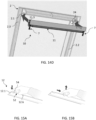
Fig. 2 is a perspective view of a roof window with the screening arrangement ofFig. 1A in an assembly condition. -
Fig. 3A is an exploded perspective view of a screening arrangement in a first embodiment. -
Fig. 3B is an exploded perspective view of a screening arrangement in a second embodiment. -
Fig. 3C is an exploded perspective view of a screening arrangement in a third embodiment. -
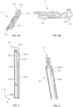
Fig. 4A is a perspective view of a connection arm of the screening arrangement of the third embodiment of the invention. -
Fig. 4B is a side view of the connection arm ofFig. 4A . -
Fig. 5 is a perspective view of a side rail of a screening arrangement in an embodiment of the invention. -
Fig. 6 is a perspective view of the connection arm of the third embodiment connected to the side rail in the embodiment ofFig. 5 . -
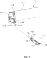
Fig. 7 is an exploded perspective view of a top element and the connection arm of the third embodiment. -
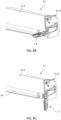
Fig. 8A is a partial exploded perspective view of the top element and the connection arm in the embodiment ofFig. 7 . -
Fig. 8B is a partial perspective view of the connection arm connected to the top element of the embodiment ofFig. 8A in a first position. -
Fig. 8C is a perspective view of the connection arm connected to the top element of the embodiment ofFig. 8A in a second position. -
Fig. 9 is a perspective view of a roof window with an internal roof window screening arrangement of a screening arrangement in an embodiment of the invention, with side rails in an assembly position. -
Fig. 10 is a perspective view of a side rail with a spring assembly in a further embodiment of the screening arrangement according to the invention. -
Figs. 11A and 11B show perspective views, from different angles, of a sledge of the spring assembly ofFig. 10 . -
Figs. 12A to 12C show schematic views of a sequence of coupling the connection arm of the third embodiment to the side rail and spring assembly of the embodiment ofFig. 10 . -
Fig. 13 is a partial perspective view of a top element, a side rail and a spring assembly in an embodiment of the internal roof window screening arrangement according to the invention. -
Figs. 14A to 14C show partial perspective views of the top element and connection arm in the embodiment ofFig. 7 in different configurations at various steps during mounting of the screening arrangement. -
Fig. 14D shows a partial perspective view of a top element and a connection arm in an embodiment of the internal roof window screening arrangement according to the invention. -
Figs. 15A and 15B show a mounting step involving activation of a biased state of the spring assembly. -
Figs. 16A to 16C show the step of connecting the side rails to the connection arms and the top element to arrive at the assembly condition. -
Figs. 17A and 17B show steps in bringing the screening arrangement from the assembly condition to the mounted condition. -
Figs. 18A and 18B show a mounting step involving deactivation of the biased state of the spring assembly to bring the screening arrangement in an embodiment of the invention to a mounted condition in a roof window. - In the following detailed description, a preferred embodiment of the present invention will be described. However, it is to be understood that features of the different embodiments are exchangeable between the embodiments and may be combined in different ways, unless anything else is specifically indicated. It may also be noted, for the sake of clarity, that the dimensions of certain components illustrated in the drawings may differ from the corresponding dimensions in real-life implementations.
- It is noted that terms such as "up", "down", "left-hand", "right-hand", "exterior", "interior", "outer", "inner" are relative and refers to the viewpoint in question. In general, when referring to an exterior side, this relates to a side of the roof window and/or screening arrangement in the mounted condition facing the outdoors or external side of the building. Conversely, an interior side refers to a side facing the internal side of the building, i.e. typically a subjacent room including any light shaft. Terms such as "outwards" and "inwards" are directions generally perpendicular to an interior-exterior direction, taking as its base point a centre of the roof window.
- Referring initially to
Figs. 1 and2 , a schematic drawing of aroof window 1 is shown from an internal, or interior, side. Typically, the roof window comprises one or more frame structures, typically astationary frame 3 and asash 2 carrying aglazing element 4 such as a transparent pane. Thesash 2 may be openable or fixed.Fig. 1 shows an embodiment of aroof window 1 comprising astationary frame 3 and anopenable sash 2. The frame structure of the roof window will in the following be represented by thesash 2 which comprises two side members 2.2 and 2.3 extending in a height direction, here denoted a longitudinal direction L. Thesash 2 further comprises a top member 2.1 and a bottom member 2.4 extending in a width direction W. The width direction Wand length direction L define a plane P (indicated inFig. 9 ), to which a depth direction D is perpendicular. Awindow opening 5 is thus formed, here defined by the inner sides of the sash members 2.1, 2.2, 2.3, 2.4, and whichwindow opening 5 is to be screened by a roofwindow screening arrangement 10 according to the invention as will be described in further detail below. In roof windows without a sash frame structure, thescreening arrangement 10 may be arranged in thestationary frame 3, such as between two side members of thestationary frame 3. - The
roof window 1 is adapted to be installed in an inclined roof, here by means of a set of frame mounting brackets connected to thestationary frame 3 and of which two representativeframe mounting brackets 6 are shown. It is noted that the inclinations shown throughout the drawings are merely representations and that an internal roofwindow screening arrangement 10 according to the invention may be mounted in aroof window 1 with an inclination different from the one indicated in these embodiments. - In
Fig. 1A , the roofwindow screening arrangement 10 is shown in a mounted condition in theroof window 1. Thescreening arrangement 10 comprises twoside rails side rail 13 is here a mirror version ofside rail 12 and the twoside rails hand side rail 12 will be made; it is to be understood that any features relating to theside rail 12 apply to theopposite side rail 13 as well. - Referring briefly also to
Fig. 5 , the twoside rails screening arrangement 10, and as shown forside rail 12, it has a side rail front 12.2 having a width dimension extending in the width direction W in the mounted condition. Finally, theside rail 12 has a track 12.1 having an extension in the depth direction D from the side rail front 12.2 and extending in the longitudinal direction L in the mounted condition of thescreening arrangement 10 as shown inFig. 1 . - The screening arrangement additionally comprises a
top element 11 extending between the two side members 2.2 and 2.3 in the mounted condition of thescreening arrangement 10, in proximity of the top member 2.1 as shown inFig. 1A . Thetop element 11 comprises a front cover 11.1 and may further comprise a back cover 11.2 and two end pieces 11.3, 11.4, with one end piece arranged at each end of thetop element 11 as is known in the art. The front cover 11.1 of thetop element 11 of thescreening arrangement 10 has a generally elongate shape and extends in the width direction W, which is the same as the lengthwise direction of the front cover 11.1. The front cover 11.1 defines a plane as indicated inFig. 3A which in the mounted condition of thescreening arrangement 10 coincides with the plane P spanned by the width direction W and length direction L of the frame structure of theroof window 1, i.e. here of thesash 2. For the sake of clarity, the plane will be referred to as the plane P during the description of thescreening arrangement 10 as such. - When referring to the side rails 12, 13 being in the mounted condition, i.e. in a position in which each
side rail side rail 12 being connected to the side member 2.2 of thesash 2 and theside rail 13 to the other side member 2.3. - In the embodiment shown, the
side rail 12 is connected to the side member 2.2 partly via thetop element 11, partly by means of aconnection part 20 provided with anadhesive portion 21 on a surface facing the side member of the frame structure in the mounted condition.Fig. 2 shows aconnection part 20 mounted on the left-hand sash side member 2.3. Theconnection part 20 is intended to provide the connection of theside rail 13 to the side member 2.3 of thesash 2 in the mounted condition of thescreening arrangement 10. Acorresponding connection part 20 is just visible on the right-hand sash side member 2.2 to provide connection of theside rail 12. Such aconnection part 20 and the mounting thereof on the side members of the sash is described in Applicant's co-pending patent application, filed on the same date as the present application. For the purposes of the present application, it is noted that it is preferred that eachconnection part 20 comprises engagement means 22 adapted to engage with therespective side rail Fig. 1C comprise an engagement tongue of a tab connected to a central portion of theconnection part 20. The tab is preferably connected to the central portion of theconnection part 20 by means of a resilient suspension ring. The engagement means 22 are adapted to engage with the track 12.1 of theside rail 12 such that theside rail 12 is freely slidable in the length direction when engaged with theconnection part 20. - The connection of the side rails 12, 13 to the
top element 11 by means of arespective connection arm 7 allowing the side rails to rotate by means of a hinge connection with thetop element 11 will be described in further detail below. - The
screening arrangement 10 additionally comprises ascreening body 15 having two side edges and a predefined length between a first end portion and a second end portion. Thescreening body 15 is movable in the longitudinal direction L between a non-screening position and a screening position in which thescreening body 15 substantially covers theglazing element 4. In the non-screening position, thescreening body 15 is configured to be accommodated in thetop element 11 as shown inFig. 2 . - In
Fig. 1 , thewindow opening 5 covered by theglazing element 4 is in turn covered by thescreening body 15. To operate thescreening body 15 of thescreening arrangement 10, abottom profile 14 is provided to extend substantially in parallel with thetop element 11 and is connected to the second end portion of thescreening body 15.Fig. 1B shows a detailed view of thebottom profile 14 with two guide elements 14.1 and 14.2 of thebottom profile 14 engaging with the side rails 12, 13. By means of the guide elements 14.1 and 14.2, side edges of thescreening body 15 and ends of thebottom profile 14 are guided on a back side of the side rails 12, 13 during screening. To provide an end stop for thebottom profile 14 in order to allow thescreening body 15 to assume a fully screening position, an end stop 14.3 is provided towards the bottom end of eachside rail Fig. 1C , for instance fastened to the bottom member 2.4 of thesash 2. - In
Fig. 1A the roofwindow screening arrangement 10 is shown in a mounted condition. A mounted condition of thetop element 11 refers to thetop element 11 being fixed in the frame structure, such as thesash 2, here to the side members 2.2, 2.3 by suitable attachment means such as mountingbrackets 24 pre-mounted at the top of each side member 2.2, 2.3 of the sash 2 (Fig. 14D ). Thetop element 11 may alternatively and/or additionally be fixed to the top member 2.1 of thesash 2, or other frame structure. - Due to the fact that the side rails 12, 13 extend at right angles to the
top element 11 in the mounted condition, they are typically packaged and transported detached from thetop element 11. Thus, bringing the side rails 12, 13 from a supply condition of thescreening arrangement 10 to the mounted condition involves connecting the side rails 12, 13 to thetop element 11 by means of a set ofconnection arms 7. Theconnection arms 7 may either be pre-connected to thetop element 11, or be supplied separately and connected to thetop element 11 during installation in preparation of the step of connecting the side rails 12, 13. Theconnection arms 7 are connected to side rails 12, 13 such that a hinge connection is formed between thetop element 11 and eachside rail Fig. 2 shows thescreening arrangement 10 at one step during the mounting procedure, thetop element 11 being already in the position it will assume in the mounted condition of thescreening arrangement 10 while the side rails 12, 13 are connected to thetop element 11 by means ofrespective connection arms 7 and assume a first position corresponding to an assembly condition of thescreening arrangement 10. - In the first position, the side rails 12, 13 and at least a part of the
respective connection arm 7 form an angle α relative to the plane P. Since internal roof window screening arrangements of the present invention are mounted in roof windows installed in roofs having an inclination with the vertical, gravity will act to swing the side rails 12, 13 towards a substantially vertical position, the side rails 12, 13 being thus allowed to hang free in the assembly condition. In order to move thescreening arrangement 10 further from the assembly condition and into the mounted condition, the side rails 12, 13 are rotated through the angle α and into a second position in which the side rails 12, 13 are located substantially in parallel with the plane P and extend along respective side members 2.2, 2.3, following which they are connected to thesash 2, or other frame structure, in any suitable manner, here as mentioned in the above by means of theconnection parts 20 fastened to the side members 2.2 or 2.3 of thesash 2. - In the assembly condition of the
screening arrangement 10, it is preferred that the hinge connection between thetop element 11 and the side rails 12, 13 allows at least temporary retention of the side rails 12, 13 on therespective connection arm 7. - One way of achieving retention is by forming the
connection arm 7 with the shape of a substantially longitudinal element, comprising a body portion with two ends, namely a first end 7.1 connected to or connectable to thetop element 11, and a second end 7.2 to engage and retain theside rail 12, for instance in the track 12.1. - In particular, it is advantageous that the
connection arm 7 and theside rail side rail side rail connection arm 7 and theside rail 12 may be frictional. - Reference is now also made to
Figs. 3A ,3B , and3C which show three alternative embodiments of theconnection arm 7. Throughout the embodiments, elements having the same or analogous function are denoted by the same reference numerals. Only differences will be described in detail. - In the embodiments of
Figs. 3A and3B , theconnection arm 7 is formed as a flexible element allowing the second end 7.2 of theconnection arm 7 to engage and follow theside rail 12 while the first end 7.1 remains stationary relative to thetop element 11. In the embodiment ofFig. 3A , the flexibility is obtained by providing a hinge 7.5 between the first and second ends 7.1 and 7.2. In the embodiment ofFig. 3B , theconnection arm 7 is a resiliently flexible element formed as a strip of elastic material. Alternatively, theconnection arm 7 could comprise a spring. At the second end 7.2 of theconnection arm 7, a latch 7.6 is formed which is configured to be received in the track 12.1 of theside rail 12, together with at least a part of theconnection arm 7. The latch 7.6 is in itself rigid, and engagement with counterpart engagement means of the side rail is made possible by the hinge functionality provided by theconnection arm 7, or by forming the engagement means of theside rail 12 as a flexible and/or elastic engagement means. The engagement means (not shown) of theside rail 12 are formed accordingly. In both of these embodiments, it is possible to connect the first end 7.1 of eachconnection arm 7 fixedly to thetop element 11 in the supply condition of thescreening arrangement 10. - In the embodiment shown in
Fig. 3C , and also in the subsequent embodiments ofFigs. 4A to 18B , theconnection arm 7 is a substantially rigid longitudinal element. Since theconnection arm 7 is rigid, i.e. is able to flex only to a limited extent, the hinge function needs to be provided by a rotational point. - While the
connection arm 7 of the third embodiment could in principle also be connected to thetop element 11 in the supply condition, theconnection arm 7 of this embodiment is able to be provided as a separate element in the supply condition and, to this end, theconnection arm 7 comprises means for releasable connection with thetop element 11. - At the first end 7.1 which is connectable to the
top element 11, the hinge connection between theconnection arm 7 andtop element 11 is in these embodiments provided by means of a hook 7.3 adapted to be connected to at least one pin 11.3ii. The hook 7.3 is here comprised in theconnection arm 7 and two pins 11.3ii are comprised in thetop element 11. Here, the hook 7.3 andconnection arm 7 are integrally formed. Alternatively, one or more pins could be comprised in theconnection arm 7 and the hook in thetop element 11. - The hook 7.3 is here a two-part hook comprising two hook arms 7.3i such that a slit 7.3ii is formed between the two hook arms 7.3i. On the
top element 11, the hinge connection means comprises two pins 11.3ii projecting in opposite directions from a pin plate 11.3i. Each hook arm 7.3i is adapted to engage with a respective pin 11.3ii on the pin plate 11.3i. This provides a more stable connection, where each of the two hook arms 7.3i engages with one of the two pins 11.3ii projecting from the pin plate 11.3i such that the slit 7.3ii is arranged between the two hook arms 7.3i in a connected condition. This arrangement limits unintentional disconnection between theconnection arm 7 and thetop element 11 such as a twist of theconnection arm 7 in a direction different from the intended hinge bend direction. - Turning to
Fig. 8A , a detailed view of the pin 11.3ii and theconnection arm 7 is shown. Each pin 11.3ii may have an elongated cross-section with a pin width PW and a pin length PL, wherein PL>PW. The hook 7.3 may have a hook opening 7.3ii with a hook opening width HOW, wherein the hook opening width is shorter than the pin length, PL>HOW, and the hook opening width is larger than the pin width, PW<HOW. HOW is measured at the outer periphery of the hook 7.3 and the narrowest part of the hook opening 7.3ii is smaller than the HOW. The narrowest part of the hook opening 7.3ii is narrower than the PW. The HOW is wider than the narrowest part of the hook opening 7.3ii. - PL being larger than the HOW ensures that the hook 7.3 and pin 11.3ii cannot be connected and disconnected when the hook opening 7.3ii is aligned with the pin length PL, as shown in
Fig. 8C . The PW being smaller than the HOW ensures that the hook 7.3 and the pin 11.3ii can be connected when these are aligned as shown inFig. 8B . Thereby, theconnection arm 7 and thetop element 11 are adapted to be connected in a limited number of ways which ensures a correct assembly of the two parts. Additionally, it limits the risk of unintentional disconnection between the two parts once they are assembled. - In
Fig. 8B , the HOW is aligned with the PW and may thereby be disconnected. Here, PL extends in the length direction parallel to the plane and the PW is arranged substantially perpendicular to the plane. In the shown embodiments, this ensures that the hook 7.3 and pin 11.3ii may only connect and disconnect when a length direction of theconnection arm 7 is arranged perpendicular to the plane. Turning toFig. 8C , theconnection arm 7 is turned such that the HOW is aligned with the PL. Theconnection arm 7 andtop element 11 are thereby arranged in a locked condition where these cannot disengage without the use of destructive force. - Referring now in particular to
Figs. 5 and 6 , the second end 7.2 of theconnection arm 7 will be described in more detail and its interaction with theside rail 12. Generally, the track 12.1 of theside rail 12 comprises two track members 12.1i extending perpendicularly from the side rail front 12.2 to form the track 12.1. Additionally, the track 12.1 comprises two track retainers 12.1ii extending from the track members 12.1i substantially in parallel with the side rail front 12.2, such that when theconnection arm 7 is inserted in the track 12.1, theconnection arm 7 is limited to a sliding movement in the length direction L. - The track retainers 12.1ii are discontinued intermittently to form one or more openings. Here, a first opening 12.4 is provided near the upper end of the
side rail 12 and a second opening 12.6 further downwards in the longitudinal direction L. - The first and second openings 12.4 and 12.6 fulfil a function when the
connection arm 7 andside rail 12 are configured to obtain a locked condition by means of a snap-lock. As shown inFigs. 4A to 4B and 6 , theconnection arm 7 is adapted to fit in the track 12.1 of theside rail 12 by insertion of the second end 7.2 in one end of the track 12.1. It is noted that the size relation between the drawings figures does not necessarily reflect the size relation of theactual connection arm 7 andside rail 12, and theconnection arm 7 is thus dimensioned to fit in the track 12.1 of theside rail 12. - In the embodiment shown, the snap-lock between the
connection arm 7 and theside rail 12 comprises a flexible tongue 7.4 arranged on theconnection arm 7 configured to interact with thefirst opening 12. 4 of the track 12.1 of theside rail 12. The locked condition is here obtained in that the flexible tongue 7.4 is pressed inwards during the passage under the track retainers 12.1ii and allowed to resume a relaxed state in the first opening 12.4 and thereby enter the locked condition shown inFig. 6 . In case it is desired to disengage theconnection arm 7 from the engagement, the flexible tongue 7.4 is pushed and guided under the track retainers 12.1ii. - The second opening 12.6 has a function in embodiments in which a spring assembly is included in the
screening arrangement 10. Such embodiments are shown inFigs. 10 to 13 . - Here, a
spring assembly 50 is provided which is configured to provide a bias on theside rail screening arrangement 10. Thespring assembly 50 interacts with theconnection arm 7 to provide the bias. Alternatively or additionally, biasing means could be provided at the bottom member 2.4 of thesash 2. - In the embodiment shown, the
spring assembly 50 comprises aspring 51 which is compressible in the longitudinal direction and asledge 52 slidable in the track 12.1 of theside rail 12. Thespring 51 is positioned to exert a force on thesledge 52, and thesledge 52 and the track 12.1 comprise complementary locking means to retain thespring 51 in a compressed state. Thesledge 52 comprises a first engagement part 52.1 configured to interact with the second end 7.2 of theconnection arm 7, a second engagement part 52.2 interacting thespring 51, and a sledge runner 52.3 interacting with the track 12.1 of theside rail 12. Finally, aflexible tongue 53 and afinger grip section 54 are provided. - In particular, the functioning of the interaction between the
side rail 12, thespring assembly 50, and theconnection arm 7 during coupling appears most clearly from the sequence shown inFigs. 12A to 12C . - As shown, the
spring 51 of thespring assembly 50 in the embodiment shown is configured to abut the second end 7.2 of theconnection arm 7 in the assembly condition and in the mounted condition. At the other end of thespring 51, a track plate 12.5 retains thespring 51 relative to the track 12.1 of theside rail 12. In order to activate the bias, thesledge 52 is configured to be manually movable between the first opening 12.4 and the second opening 12.6 in the track 12.1 of theside rail 12, in that thespring 51 is in a compressed state when positioned in the second opening 12.6. - In the following, a method of mounting of the
screening arrangement 10 from the supply condition to the mounted condition will be described with particular reference toFigs. 14A to 18B . Reference is also made to the embodiments described in the above. - As a first step, if provided separately, the
connection arms 7 are connected to thetop casing 11 and if required brought to a suitable position to allow connection with the side rails 12, 13. This is reflected inFigs. 14A to 14C . - Subsequently, the
top casing 11 with attachedconnection arms 7 is connected to thesash 2 by inserting the end pieces 11.3, 11.4 over mountingbrackets 24 at the side members 2.2, 2.3 of the sash as indicated inFig. 14D . Thespring assembly 50 is biased by moving thesledge 52 by gripping thefinger grip section 54, from the first opening 12.4 to the second opening 12.6 as shown inFigs. 15A and 15B . - The side rails 12, 13 are then connected to the
respective connection arm 7 and thus to thetop element 11 as indicated inFigs. 16A to 16C . When thescreening arrangement 10 is installed inroof window 1 in a roof with an inclination, thescreening arrangement 10 will itself be inclined relative to the ground. Thus, since the side rails 12, 13 are hingedly connected to thetop element 11 and are allowed to hang free in the assembly position, the side rails 12, 13 will become substantially vertically arranged due to the pull of gravity. - In
Fig. 17A , it is shown how the person performing the mounting takes hold of theside rail 12 and rotates it out of the vertical position in the direction towards the exterior until theside rail 12 is parallel to the plane P and the engagement means 22 of theconnection part 20 is guided into the track 12.1 of the side rail. During this movement, the upper edge of theside rail 12 is arranged behind the front cover 11.1 of thetop element 11 as shown in the enlarged cut-out ofFig. 17B . Alternative configurations include that the front cover 11.1 of the top element and side rail front 12.2 are arranged to form a uniform front towards the interior such as a mitre joint. - The side rails 12, 13 may as shown be mounted independently of each other, that is, one side rail may be connected to the
connection arm 7 and then rotated into position and fixed in its mounted position while the other side rail is still in its supply condition. Or, as in the embodiments described, both side rails 12, 13 are connected torespective connection arms 7 and allowed to hang free before rotating one after the other into position. A further alternative is to take hold of both side rails 12, 13 at the same time from their free-hanging position and then rotate into place. - Finally,
Figs. 18A and 18B show how thespring 51 of thespring assembly 50 is allowed to exert its bias by moving thesledge 52 by itsfinger grip section 54 such that theside rail 12 is pressed downwards, thus providing a compression mount. - The invention is not limited to the embodiments shown and described in the above, but various modifications and combinations may be carried out.
-
- 1
- roof window
- 2
- frame structure / sash
- 2.1
- top member
- 2.2
- side member
- 2.3
- side member
- 2.4
- bottom member
- 3
- stationary frame
- 4
- glazing element / pane
- 5
- window opening
- 6
- mounting bracket
- 7
- connection arm
- 7.1
- first end of connection arm
- 7.2
- second end of connection arm
- 7.3
- hook
- 7.3i
- hook arm
- 7.3ii
- hook opening
- 7.4
- flexible tongue
- 7.5
- hinge
- 7.6
- latch
- 10
- screening arrangement
- 11
- top element
- 11.1
- front cover
- 11.2
- back cover
- 11.3
- end piece
- 11.3i
- pin plate
- 11.3ii
- pin
- 11.4
- end piece
- 11.4i
- pin plate
- 11.4ii
- pin
- 12
- side rail
- 12.1
- track
- 12.1i
- track member
- 12.1ii
- track retainer
- 12.2
- side rail front
- 12.4
- opening
- 12.5
- track plate
- 12.6
- second opening
- 13
- side rail
- 14
- bottom profile
- 14.1
- guide element
- 14.2
- guide element
- 14.3
- end stop
- 15
- screening body
- 15.1
- end cap
- 20
- connection part
- 21
- adhesive portion
- 22
- engagement means
- 24
- mounting bracket
- 50
- spring assembly
- 51
- spring
- 52
- sledge
- 52.1
- first engagement part
- 52.2
- second engagement part
- 52.3
- sledge runner
- 53
- flexible tongue
- 54
- finger grip section
- α
- angle
- L
- longitudinal direction
- W
- width direction
- D
- depth direction
- P
- plane
Claims (16)
- An internal roof window screening arrangement (10) for mounting in a roof window (1), the roof window (1) having a frame structure (2) comprising a top member (2.1) and a bottom member (2.4) extending in a width direction (W) and two mutually parallel side members (2.2, 2.3) extending in a longitudinal direction (L), the width direction (W) and longitudinal direction (L) defining a plane (P),the screening arrangement (10) comprising a top element (11) including a front cover (11.1) configured to extend in the width direction (W) in a mounted condition of the screening arrangement (10), and two side rails (12, 13),wherein the screening arrangement (10) is configured to be brought from a supply condition in which said side rails (12, 13) are detached from the top element (11) to the mounted condition in which the side rails (12, 13) are connected to the top element (10) and to respective side members (2.2, 2.3) of the frame structure (2) and extending substantially in said plane (P),characterised in thatthe screening arrangement (10) further comprises a set of connection arms (7), each connection arm (7) comprising a first end (7.1) connected to or connectable to the top element (11), and each connection arm (7) being further adapted to be connected to the respective side rail (12, 13) at a second end (7.2) such that a hinge connection is formed between the top element (11) and each side rail (12, 13),and in that each side rail (12, 13) and at least a part of the respective connection arm (7) when connected to the top element (11) are configured to assume a first position at an angle (α) relative to said plane (P) corresponding to an assembly condition and a second position in which the side rail (12, 13) is parallel to the plane (P) corresponding to the mounted condition, the side rails (12, 13) being allowed to hang free substantially vertically in the assembly condition, and each side rail (12, 13) being configured to be fixed to the frame structure (2) in the second position to obtain the mounted condition in which each side rail (11, 12) extends along a side member (2.2, 2.3) of the frame structure (2).
- An internal roof window screening arrangement (10) according to claim 1, wherein each side rail (12) comprises a track (12.1), and the side rail (12) is adapted to connect with the connection arm (7) by receiving at least a part of the connection arm (7) in the track (12.1).
- An internal roof window screening arrangement (10) according to any of the preceding claims, wherein each connection arm (7) and the corresponding side rail (12, 13) are adapted to obtain a locked condition by means of a snap-lock, the snap-lock being preferably configured to allow movement of the side rail (12, 13) in an upwards direction in the longitudinal direction (L) but prevents movement of the side rail (12, 13) in a downwards direction.
- An internal roof window screening arrangement (10) according to claim 3, wherein the snap-lock comprises a flexible tongue (7.4) arranged on the connection arm (7) configured to interact with the track (12.1, 13.1) of the side rail (12) to obtain the locked condition, preferably the flexible tongue (7.4) and connection arm (7) are integrally formed.
- An internal roof window screening arrangement (10) according to any one of claims 2 to 3, wherein the connection arm (7) comprises a latch (7.6) configured to interact with engagement means in the track in the side rail.
- An internal roof window screening arrangement (10) according to any one the preceding claims, wherein the hinge connection between the top element (11) and each side rail (12, 13) is formed by providing the connection arm (7) as a flexible element, preferably a resiliently flexible element, more preferably formed as a flexible spring or a strip of elastic material.
- An internal roof window screening arrangement (10) according to any one the preceding claims, wherein the first end (7.1) of each connection arm (7) is fixedly connected to the top element (11) in the supply condition.
- An internal roof window screening arrangement (10) according to any one of claims 1 to 6, wherein each connection arm (7) is provided as a separate element in the supply condition and comprises means for releasable connection with the top element (11).
- An internal roof window screening arrangement (10) according to claim 8, wherein the hinge connection between the connection arm (7) and top element (11) is provided by means of a hook (7.3) adapted to connect to at least one pin (11.3ii), the first end (7.1) of the connection arm (7) preferably comprising the hook (7.3), and the at least one pin (11.3ii) more preferably extending from the top element (11).
- An internal roof window screening arrangement (10) according to claim 9, wherein the hook (7.3) is a two-part hook comprising two hook arms (7.3i) such that a slit (7.3ii) is formed between the two hook arms (7.3i), and the hinge connection comprises two pins (11.3ii) projecting in opposite directions from a pin plate (11.3i), wherein the pin plate (11.3) is adapted to engage with the slit and each hook arm (7.2i, 7.2ii) is adapted to engage with one of the two pins (11.2i, 11.2ii).
- An internal roof window screening arrangement (10) according to any one of claims 9 to 10, wherein the at least one pin (11.3ii) has an elongated cross-section with a pin width (PW) and a pin length (PL), and the hook (7.3) has a hook opening (7.3ii) with a hook opening width (HOW), wherein the hook opening width (HOW) is shorter than the pin length (PL) and larger than the pin width (PW).
- An internal roof window screening arrangement (10) according to any one the preceding claims, wherein the screening arrangement (10) further comprises a spring assembly (50) configured to provide a bias on the side rail (12, 13) in the longitudinal direction (L), preferably via the connection arm (7) or on the bottom member (2.4) of the frame structure (2) in the mounted condition.
- An internal roof window screening arrangement (10) according to claim 12, wherein the spring assembly (50) comprises a spring (51) which is compressible in the longitudinal direction and a sledge (52) slidable in a track (12.1) of the side rail (12, 13), the spring (51) being positioned to exert a force on the sledge (52), and wherein the sledge (52) and the track (12.1) comprise complementary locking means to retain the spring (51) in a compressed state, the spring (51) of the spring assembly (50) being preferably configured to abut the second end (7.2) of the connection arm (7) in the assembly condition and in the mounted condition, and wherein the sledge (52) is configured to be manually movable between a first opening (12.4) and a second opening (12.6) in the track (12.1) of the side rail (12, 13), the spring (51) being in a compressed state when positioned in the second opening (12.6).
- An internal roof window screening arrangement (10) according to any one of the preceding claims, wherein each side rail (12, 13) is adapted to be mounted on a side member (2.2, 2.3) of the frame structure (2) by means of at least one connection part (20) to obtain a mounted condition, each connection part (20) being mounted on the side member (2.2, 2.3) by means of an adhesive portion (21), and wherein each connection part (20) preferably further comprises engagement means (22) adapted to engage with the side rail (12, 13) to obtain the mounted condition, said engagement means (22) more preferably comprising an engagement tongue of a tab connected to a central portion of the connection part (20), the tab being still more preferably connected to the central portion of the connection part (20) by means of a resilient suspension ring, said engagement means (22) being even still more preferably adapted to engage with a track (12.1) of the side rail (12) such that the side rail (12) is freely slidable in the length direction when engaged with the connection part (20).
- An internal roof window screening arrangement (10) according to any one of the preceding claims, wherein the top element (11) comprises two end pieces (11.3, 11.4) at respective longitudinal ends of the top element (11), and wherein the top element (11) is mounted to the frame structure (11) by means of the end pieces (11.3, 11.4) engaging with mounting brackets (24) provided on side members (2.2, 2.3) of the frame structure (2) in a snap engagement.
- A method for installing an internal roof window screening arrangement (10) according to any one of the preceding claims in a roof window (1), comprising the steps of;- mounting the top element (11) of the screening arrangement (10) between the two side members (2.2, 2.3) and proximal to the top member (2.1) of the frame,- optionally connecting the first end (7.1) of each connection arm (7) to the top element (11),- optionally positioning the connection arm (7) at an angle α relative to said plane (P),- connecting a side rail (12, 13) to the respective connection arm (7),- allowing the side rails (12, 13) to assume a substantially vertical position to hang free in the assembly condition,- rotating the side rail (12) into the second position parallel to the plane (P) corresponding to the mounted condition,- connecting the side rail (12) to the frame structure (2) to obtain the mounted condition.
Applications Claiming Priority (1)
| Application Number | Priority Date | Filing Date | Title |
|---|---|---|---|
| DKPA202370309 | 2023-06-19 |
Publications (1)
| Publication Number | Publication Date |
|---|---|
| EP4481152A1 true EP4481152A1 (en) | 2024-12-25 |
Family
ID=91585332
Family Applications (1)
| Application Number | Title | Priority Date | Filing Date |
|---|---|---|---|
| EP24182901.9A Pending EP4481152A1 (en) | 2023-06-19 | 2024-06-18 | An internal roof window screening arrangement with a connection arm and method for installing such a screening arrangement |
Country Status (2)
| Country | Link |
|---|---|
| EP (1) | EP4481152A1 (en) |
| CN (1) | CN222924031U (en) |
Citations (4)
| Publication number | Priority date | Publication date | Assignee | Title |
|---|---|---|---|---|
| CH689764A5 (en) * | 1994-03-02 | 1999-10-15 | Reflexa Werke H P Albrecht | Roller shutters. |
| EP1045107A1 (en) * | 1999-04-16 | 2000-10-18 | Bubendorff Volet Roulant Société Anonyme | Roller shutter with a roller supported by corner pieces |
| EP1847677A2 (en) * | 2006-04-20 | 2007-10-24 | Delphia S.A.R.L. | Tunnel-shaped housing for a roller blind designed to be assembled with a window frame |
| WO2008131759A1 (en) | 2007-04-26 | 2008-11-06 | Vkr Holding A/S | A screening arrangement comprising means for mounting side rails and method of mounting such a screening arrangement |
-
2024
- 2024-06-18 EP EP24182901.9A patent/EP4481152A1/en active Pending
- 2024-06-19 CN CN202421408501.9U patent/CN222924031U/en active Active
Patent Citations (4)
| Publication number | Priority date | Publication date | Assignee | Title |
|---|---|---|---|---|
| CH689764A5 (en) * | 1994-03-02 | 1999-10-15 | Reflexa Werke H P Albrecht | Roller shutters. |
| EP1045107A1 (en) * | 1999-04-16 | 2000-10-18 | Bubendorff Volet Roulant Société Anonyme | Roller shutter with a roller supported by corner pieces |
| EP1847677A2 (en) * | 2006-04-20 | 2007-10-24 | Delphia S.A.R.L. | Tunnel-shaped housing for a roller blind designed to be assembled with a window frame |
| WO2008131759A1 (en) | 2007-04-26 | 2008-11-06 | Vkr Holding A/S | A screening arrangement comprising means for mounting side rails and method of mounting such a screening arrangement |
Also Published As
| Publication number | Publication date |
|---|---|
| CN222924031U (en) | 2025-05-30 |
Similar Documents
| Publication | Publication Date | Title |
|---|---|---|
| US6550733B1 (en) | Supporting means for a screening device | |
| US5301989A (en) | Tilt lock for double-hung windows | |
| EP0876544B1 (en) | A screening device for a wall opening | |
| JP3390048B2 (en) | Double window tilt sash type window system | |
| JP3226418U (en) | Hinge for windows, windows including a series of such hinges, and method of installing such windows | |
| KR102072952B1 (en) | Awning for Vehicle | |
| CN207499666U (en) | hinges for windows | |
| EP2492433B1 (en) | Wind-up-screen | |
| CN204199549U (en) | With the femerell of overburden fastener | |
| CN222924031U (en) | Internal roof window shielding device | |
| CN101868592B (en) | Screening device as add-on for a screening arrangement | |
| PL212427B1 (en) | Skylight | |
| KR20110003068A (en) | Glazing Bead Bonder in Aluminum Window | |
| EP4481132A1 (en) | An internal roof window screening arrangement with a connection part comprising engagement means for engagement with a side rail | |
| EP2037168B1 (en) | Push-push fixture clip | |
| CN218438830U (en) | Shutter locking assembly | |
| DK179698B1 (en) | A roof window with an improved hinge and covering assembly, and a method of providing such a hinge and covering assembly | |
| JP3057832U (en) | A dome for astronomical observation that can be disassembled and assembled | |
| MX2012010222A (en) | Spring latch and method for attaching a seat cushion to a seat frame. | |
| KR20110036169A (en) | Window lock | |
| KR102033497B1 (en) | A Fixed apparatus of Sliding roof | |
| EP1335096B1 (en) | Door with enhancing horizontal sections | |
| JP2536822Y2 (en) | Folding door fixing device | |
| JP2006167438A (en) | Hook for reed screen and reed screen mounting structure using the same | |
| JP2004204530A (en) | Shutter |
Legal Events
| Date | Code | Title | Description |
|---|---|---|---|
| PUAI | Public reference made under article 153(3) epc to a published international application that has entered the european phase |
Free format text: ORIGINAL CODE: 0009012 |
|
| STAA | Information on the status of an ep patent application or granted ep patent |
Free format text: STATUS: THE APPLICATION HAS BEEN PUBLISHED |
|
| AK | Designated contracting states |
Kind code of ref document: A1 Designated state(s): AL AT BE BG CH CY CZ DE DK EE ES FI FR GB GR HR HU IE IS IT LI LT LU LV MC ME MK MT NL NO PL PT RO RS SE SI SK SM TR |
|
| STAA | Information on the status of an ep patent application or granted ep patent |
Free format text: STATUS: REQUEST FOR EXAMINATION WAS MADE |
|
| 17P | Request for examination filed |
Effective date: 20250624 |