EP4481032A1 - Microfluidic device and method for using microfluidic device - Google Patents
Microfluidic device and method for using microfluidic device Download PDFInfo
- Publication number
- EP4481032A1 EP4481032A1 EP22927283.6A EP22927283A EP4481032A1 EP 4481032 A1 EP4481032 A1 EP 4481032A1 EP 22927283 A EP22927283 A EP 22927283A EP 4481032 A1 EP4481032 A1 EP 4481032A1
- Authority
- EP
- European Patent Office
- Prior art keywords
- flow path
- principal surface
- microfluidic device
- end open
- space
- Prior art date
- Legal status (The legal status is an assumption and is not a legal conclusion. Google has not performed a legal analysis and makes no representation as to the accuracy of the status listed.)
- Pending
Links
Images






Classifications
-
- C—CHEMISTRY; METALLURGY
- C12—BIOCHEMISTRY; BEER; SPIRITS; WINE; VINEGAR; MICROBIOLOGY; ENZYMOLOGY; MUTATION OR GENETIC ENGINEERING
- C12M—APPARATUS FOR ENZYMOLOGY OR MICROBIOLOGY; APPARATUS FOR CULTURING MICROORGANISMS FOR PRODUCING BIOMASS, FOR GROWING CELLS OR FOR OBTAINING FERMENTATION OR METABOLIC PRODUCTS, i.e. BIOREACTORS OR FERMENTERS
- C12M23/00—Constructional details, e.g. recesses, hinges
- C12M23/02—Form or structure of the vessel
- C12M23/16—Microfluidic devices; Capillary tubes
-
- C—CHEMISTRY; METALLURGY
- C12—BIOCHEMISTRY; BEER; SPIRITS; WINE; VINEGAR; MICROBIOLOGY; ENZYMOLOGY; MUTATION OR GENETIC ENGINEERING
- C12M—APPARATUS FOR ENZYMOLOGY OR MICROBIOLOGY; APPARATUS FOR CULTURING MICROORGANISMS FOR PRODUCING BIOMASS, FOR GROWING CELLS OR FOR OBTAINING FERMENTATION OR METABOLIC PRODUCTS, i.e. BIOREACTORS OR FERMENTERS
- C12M25/00—Means for supporting, enclosing or fixing the microorganisms, e.g. immunocoatings
- C12M25/14—Scaffolds; Matrices
-
- B—PERFORMING OPERATIONS; TRANSPORTING
- B01—PHYSICAL OR CHEMICAL PROCESSES OR APPARATUS IN GENERAL
- B01L—CHEMICAL OR PHYSICAL LABORATORY APPARATUS FOR GENERAL USE
- B01L2200/00—Solutions for specific problems relating to chemical or physical laboratory apparatus
- B01L2200/06—Fluid handling related problems
- B01L2200/0647—Handling flowable solids, e.g. microscopic beads, cells, particles
- B01L2200/0668—Trapping microscopic beads
-
- B—PERFORMING OPERATIONS; TRANSPORTING
- B01—PHYSICAL OR CHEMICAL PROCESSES OR APPARATUS IN GENERAL
- B01L—CHEMICAL OR PHYSICAL LABORATORY APPARATUS FOR GENERAL USE
- B01L2300/00—Additional constructional details
- B01L2300/06—Auxiliary integrated devices, integrated components
- B01L2300/069—Absorbents; Gels to retain a fluid
-
- B—PERFORMING OPERATIONS; TRANSPORTING
- B01—PHYSICAL OR CHEMICAL PROCESSES OR APPARATUS IN GENERAL
- B01L—CHEMICAL OR PHYSICAL LABORATORY APPARATUS FOR GENERAL USE
- B01L2300/00—Additional constructional details
- B01L2300/08—Geometry, shape and general structure
- B01L2300/0848—Specific forms of parts of containers
- B01L2300/0858—Side walls
-
- B—PERFORMING OPERATIONS; TRANSPORTING
- B01—PHYSICAL OR CHEMICAL PROCESSES OR APPARATUS IN GENERAL
- B01L—CHEMICAL OR PHYSICAL LABORATORY APPARATUS FOR GENERAL USE
- B01L3/00—Containers or dishes for laboratory use, e.g. laboratory glassware; Droppers
- B01L3/50—Containers for the purpose of retaining a material to be analysed, e.g. test tubes
- B01L3/502—Containers for the purpose of retaining a material to be analysed, e.g. test tubes with fluid transport, e.g. in multi-compartment structures
- B01L3/5027—Containers for the purpose of retaining a material to be analysed, e.g. test tubes with fluid transport, e.g. in multi-compartment structures by integrated microfluidic structures, i.e. dimensions of channels and chambers are such that surface tension forces are important, e.g. lab-on-a-chip
- B01L3/502761—Containers for the purpose of retaining a material to be analysed, e.g. test tubes with fluid transport, e.g. in multi-compartment structures by integrated microfluidic structures, i.e. dimensions of channels and chambers are such that surface tension forces are important, e.g. lab-on-a-chip specially adapted for handling suspended solids or molecules independently from the bulk fluid flow, e.g. for trapping or sorting beads or physically stretching molecules
Definitions
- the present invention relates to a microfluidic device and a method for using the microfluidic device.
- 3D gel culture allows cells to three-dimensionally grow, which makes it possible to carry out a study using a structure closer to in vivo conditions as compared to conventional two-dimensional cell culture. Therefore, study results unique to 3D gel culture are expected, such as tissue formation, such as organoid formation, that cannot be performed by conventional two-dimensional culture, application to regenerative medicine, analysis of pharma-cokinetics in a three-dimensional environment close to in vivo conditions, and a study of cell-to-cell interactions.
- a device for 3D gel culture such a device using a cell culture insert as disclosed in Patent Document 1 mentioned below is generally used.
- a device using micro flow paths (MPS) hereinafter, also referred to as a microfluidic device
- Patent Document 2 has been developed as a new technology.
- Such a conventional device having a cell culture insert has an advantage that a flat gel surface that enables cell seeding and has excellent observability can be constructed in the device, but has a problem that advantages of a microfluidic device cannot be adopted, such as that the size, shape, and oxygen concentration of a cell culture environment can be made close to those in vivo.
- a microfluidic device has the above-described unique advantage, but has a problem that a flat gel surface excellent in observability cannot be constructed in the device.
- the present invention is directed to a microfluidic device including: a plate-shaped main body having a first principal surface and a second principal surface facing each other in a first direction; a first flow path formed inside the main body and extending along a plane between the first principal surface and the second principal surface; and a plurality of first flow path ports extending in the first direction and each having one end open to an end of the first flow path and another end open to the second principal surface, in which the first flow path has an enlarged part so that a flow path width increases from a first principal surface side toward a second principal surface side when the first flow path is viewed in its extension direction.
- Such a microfluidic device enables cell seeding on the top surface of a gel because a space is maintained above the gel formed in the first flow path, and is excellent in observability because a flat gel surface can be formed.
- the present invention is also directed to a method for using the above-described microfluidic device, the method including:
- Such a method for using the microfluidic device enables cell seeding on the top surface of a gel because a space is maintained above the gel formed in the first flow path, and is excellent in observability because a flat gel surface can be formed.
- Fig. 1 is a perspective view of a microfluidic device 100 according to a first embodiment.
- the microfluidic device 100 includes a main body 1 having a first principal surface 1a and a second principal surface 1b.
- the first principal surface 1a and the second principal surface 1b are disposed so as to face each other.
- an XYZ coordinate system is appropriately referenced in which a plane parallel to the first principal surface 1a and the second principal surface 1b is defined as an XY plane and a direction orthogonal to the XY plane is defined as a Z direction.
- the main body 1 is formed in a plate shape so as to have the first principal surface 1a and the second principal surface 1b facing each other in the Z direction.
- the Z direction in the present embodiment corresponds to a "first direction”. It should be noted that the microfluidic device 100 is usually used so that the Z direction corresponds to a vertical direction, and the -Z direction corresponds to an upward direction.
- the microfluidic device 100 includes a first flow path 2 formed inside the main body 1.
- the first flow path 2 extends along the XY plane between the first principal surface 1a and the second principal surface 1b, and specifically extends in the X direction. Both ends 2a and 2b of the first flow path 2 are located inside the microfluidic device 100.
- the microfluidic device 100 includes first flow path ports 3 and 4 extending in the Z direction.
- the first flow path port 3 is connected to the one end 2a of the first flow path 2, and the first flow path port 4 is connected to the other end 2b of the first flow path 2.
- the first flow path port 3 has one end open to the one end 2a of the first flow path 2 and another end open to the second principal surface 1b.
- the first flow path port 4 has one end open to the other end 2b of the first flow path 2 and another end open to the second principal surface 1b.
- the first flow path ports 3 and 4 have at least one purpose selected from the purpose of injecting a liquid into the microfluidic device 100 and the purpose of discharging a liquid from the microfluidic device 100.
- the first flow path port 3 may be used as a liquid inlet and the first flow path port 4 may be used as a liquid outlet.
- the first flow path 2 of the first embodiment includes a first space 21 and a second space 22 adjacent to the first space 21 on the second principal surface 1b side in the Z direction (-Z direction side).
- the first space 21 has a rectangular cross-section in a YZ plane.
- the second space 22 has a trapezoidal cross-section in the YZ plane.
- the second space 22 has side walls 22a and 22b, and the side walls 22a and 22b are inclined with respect to the Z direction so as to separate from each other as extending toward the second principal surface 1b.
- the side walls 22a and 22b of the second space 22 allow a flow path width 2w of the first flow path 2 in the Y direction to increase from the first principal surface 1a side toward the second principal surface 1b side. That is, the side walls 22a and 22b of the second space 22 in the first embodiment correspond to "enlarged parts" in the present invention.
- a virtual surface 20 formed by connecting the first principal surface 1a-side end of the side wall 22a and the first principal surface 1a-side end of the side wall 22b, specifically an interface 20 between the first space 21 and the second space 22 is parallel to the first principal surface 1a.
- the microfluidic device 100 includes a plate-shaped main body 1 having a first principal surface 1a and a second principal surface 1b facing each other in the Z direction, a first flow path 2 formed inside the main body 1 and extending along the XY plane between the first principal surface 1a and the second principal surface 1b, and first flow path ports 3 and 4 extending in the Z direction and each having one end open to an end 2a or 2b of the first flow path 2 and another end open to the second principal surface 1b.
- the first flow path 2 has side walls 22a and 22b (enlarged parts) so that a flow path width 2w increases from the first principal surface 1a side toward the second principal surface 1b side when the first flow path 2 is viewed in its extension direction (X direction).
- X direction extension direction
- the first flow path 2 includes a first space 21 and a second space 22 that is adjacent to the first space 21 on the second principal surface 1b side in the Z direction and that has a larger flow path width 2w than the first space 21 by the side walls 22a and 22b (enlarged parts).
- the side walls 22a and 22b (enlarged parts) provide surfaces inclined with respect to the first principal surface 1a.
- the first flow path 2 has side walls 22a and 22b (enlarged parts) on its both sides in the Y direction respectively, and a virtual surface 20 formed by connecting together the first principal surface 1a-side end of the side wall 22a and the first principal surface 1a-side end of the side wall 22b is parallel to the first principal surface 1a.
- Fig. 4A to Fig. 4D are sectional views schematically illustrating the method for using the microfluidic device 100.
- the method for using the microfluidic device 100 includes: a first step (shown in Fig. 4A ) in which the microfluidic device 100 is disposed so that the first principal surface 1a is located on a lower side and the second principal surface 1b is located on an upper side; a second step (shown in Fig. 4B ) in which a sol S is injected into a region below the side walls 22a and 22b of the second space 22 in the first flow path 2, and a third step (shown in Fig.
- the method for using the microfluidic device 100 may further include a fourth step (shown in Fig. 4D ) in which a culture solution is injected into a region above the gel G in the first flow path 2 to culture the cells C.
- the sol S herein means a solution in which colloidal particles (dispersoid) are contained in a dispersion medium
- the gel G herein refers to one obtained by solidifying the sol S into a jelly-like state.
- a sol S is injected through the first flow path port 3 or the first flow path port 4.
- the amount of the sol S to be injected is equal to or less than an amount corresponding to the volume of the first space 21, preferably equal to an amount corresponding to the volume of the first space 21.
- the sol S injected through the first flow path port 3 or the first flow path port 4 remains in the first space 21 under the action of surface tension.
- Surface tension is the property of a liquid or solid to minimize its surface area as much as possible, and can quantitatively be represented as surface free energy per unit area in the unit of mJ/m 2 .
- Fig. 6 is a sectional view of a comparative example in which the flow path width of a first flow path 2P in the Y direction is constant in the Z direction.
- a sol S is in contact with the ceiling of the first flow path 2P when flowing into the first flow path 2P.
- the sol S is solidified in such a state, cells C cannot be seeded on the top surface of a gel, and a culture solution cannot be perfused, either.
- the reason why the sol S flows into the first flow path 2P in such a manner as shown in Fig. 6 is that a liquid (here, the sol S) flows into the first flow path 2P so that the total exposed surface area of the liquid (the area of the liquid-gas interface) is minimized for energetic stability.
- the second space 22 is maintained above the gel G so that cells C can be seeded on the top surface of the gel G in the third step.
- the cells C can be seeded by injecting a culture solution containing the cells C into the second space 22. Since the side walls 22a and 22b (enlarged parts) provide surfaces inclined with respect to the first principal surface 1a, the cells C can be prevented from adhering to surfaces other than the top surface of the gel 2 when the cells C are seeded.
- the cells C can be cultured by injecting a culture solution into a region above the gel G in the fourth step.
- the cells C after cultivation are observed through the first principal surface 1a with a microscope from the outside of the microfluidic device 100.
- the microfluidic device 100 according to the present invention is excellent in observability because the top surface of the gel G is flat and the parallel to the first principal surface 1a. It should be noted that the present embodiment has been described with reference to a case where the first principal surface 1a and the top surface of the gel G are parallel to each other, but when the microfluidic device 100 has a frame surrounding the first principal surface 1a, the top surface of the gel G shall be parallel to the bottom surface of the frame.
- the gel G is selected from the group consisting of collagen, gelatin, hyaluronate, hyaluronan, fibrin, alginate, agarose, chitosan, chitin, cellulose, pectin, starch, laminin, fibrinogen/thrombin, fibrillin, elastin, gum, cellulose, agar, gluten, casein, albumin, vitronectin, tenascin, entactin/nidogen, glycoprotein, glycosaminoglycan, poly(acrylic acid) and derivatives thereof, poly(ethylene oxide) and copolymers thereof, poly(vinyl alcohol), polyphosphazene, Matrigel, and combinations of two or more of them.
- Fig. 7 is a perspective view of a microfluidic device 100A according to a second embodiment.
- Fig. 8 is a sectional view of the microfluidic device 100A taken along a line VIII-VIII shown in Fig. 7
- Fig. 9 is a sectional view of the microfluidic device 100A taken along a line IX-IX shown in Fig. 7 .
- the first flow path 2 in the second embodiment includes projections 9 that project from side walls 2c and 2d in the Y direction and extend in the X direction.
- the projections 9 project from the central regions of both of the side walls 2c and 2d in the Z direction, respectively.
- Each of the projections 9 has a triangular cross-section in the YZ plane.
- Each of the projections 9 has a lower surface 9a on the first principal surface 1a side (+Z direction side) and an upper surface 9b on the second principal surface 1b side (-Z direction side).
- the lower surface 9a is parallel to the first principal surface 1a.
- the upper surface 9b is inclined with respect to the first principal surface 1a.
- the upper surface 9b is inclined so as to depart from the first principal surface 1a as extending from the tip of the projection 9 toward the side wall 2c or 2d. This allows the flow path width 2w of the first flow path 2 in the Y direction to increase from the first principal surface 1a side toward the second principal surface 1b side in a region where the projections 9 are formed.
- the upper surfaces 9b of the projections 9 in the second embodiment correspond to "enlarged parts" in the present invention. It should be noted that in a region where the projections 9 are not formed, both of the side walls 2c and 2d of the first flow path 2 in the Y direction are parallel to each other.
- the microfluidic device 100A includes a plate-shaped main body 1 having a first principal surface 1a and a second principal surface 1b facing each other in the Z direction, a first flow path 2 formed inside the main body 1 and extending along the XY plane between the first principal surface 1a and the second principal surface 1b, and first flow path ports 3 and 4 extending in the Z direction and each having one end open to an end of the first flow path 2 and another end open to the second principal surface 1b.
- the first flow path 2 has upper surfaces 9b of projections 9 (enlarged parts) so that a flow path width 2w increases from the first principal surface 1a side toward the second principal surface 1b side when the first flow path 2 is viewed in its extension direction (X direction).
- the upper surfaces 9b of the projections 9 are inclined with respect to the first principal surface 1a.
- the first flow path 2 has upper surfaces 9b of projections 9 (enlarged parts) on its both sides in the Y direction respectively, and a virtual surface 20 formed by connecting together the first principal surface 1a-side ends of the upper surfaces 9b is parallel to the first principal surface 1a.
- glycerol or thermal phase transition hydrogel G1 is injected through the second flow path port 53.
- the amount of the glycerol or thermal phase transition hydrogel G1 to be injected is set so that the height of the injected glycerol or thermal phase transition hydrogel G1 is higher than the upper wall surface 51t of the second flow path 51 and the upper wall surface 52t of the third flow path 52 and lower than the virtual surface 20.
- a sol S is injected through the first flow path port 3 so as to spread on the glycerol or thermal phase transition hydrogel G1 and is then gelatinized. At this time, the sol S is injected into a region below the virtual surface 20 in the first flow path 2.
- the glycerol or thermal phase transition hydrogel G1 is removed through the second flow path port 53 or the third flow path port 54.
- a gel G remains, and spaces are created above and below the gel G in the first flow path 2.
Landscapes
- Health & Medical Sciences (AREA)
- Chemical & Material Sciences (AREA)
- Wood Science & Technology (AREA)
- Organic Chemistry (AREA)
- Life Sciences & Earth Sciences (AREA)
- Engineering & Computer Science (AREA)
- Bioinformatics & Cheminformatics (AREA)
- Zoology (AREA)
- Biomedical Technology (AREA)
- Sustainable Development (AREA)
- Microbiology (AREA)
- Biotechnology (AREA)
- Biochemistry (AREA)
- General Engineering & Computer Science (AREA)
- General Health & Medical Sciences (AREA)
- Genetics & Genomics (AREA)
- Immunology (AREA)
- Dispersion Chemistry (AREA)
- Clinical Laboratory Science (AREA)
- Micromachines (AREA)
- Apparatus Associated With Microorganisms And Enzymes (AREA)
Abstract
Description
- The present invention relates to a microfluidic device and a method for using the microfluidic device.
- 3D gel culture (three-dimensional gel culture) allows cells to three-dimensionally grow, which makes it possible to carry out a study using a structure closer to in vivo conditions as compared to conventional two-dimensional cell culture. Therefore, study results unique to 3D gel culture are expected, such as tissue formation, such as organoid formation, that cannot be performed by conventional two-dimensional culture, application to regenerative medicine, analysis of pharma-cokinetics in a three-dimensional environment close to in vivo conditions, and a study of cell-to-cell interactions.
- As a device for 3D gel culture, such a device using a cell culture insert as disclosed in
Patent Document 1 mentioned below is generally used. On the other hand, a device using micro flow paths (MPS) (hereinafter, also referred to as a microfluidic device) disclosed inPatent Document 2 mentioned below has been developed as a new technology. -
- Patent Document 1:
JP-A-2020-202754 - Patent Document 2:
JP-T-2018-522586 - Such a conventional device having a cell culture insert has an advantage that a flat gel surface that enables cell seeding and has excellent observability can be constructed in the device, but has a problem that advantages of a microfluidic device cannot be adopted, such as that the size, shape, and oxygen concentration of a cell culture environment can be made close to those in vivo. On the other hand, a microfluidic device has the above-described unique advantage, but has a problem that a flat gel surface excellent in observability cannot be constructed in the device.
- In light of the above problems, it is an object of the present invention to provide a microfluidic device capable of constructing a gel surface that enables cell seeding and has excellent observability and a method for using the microfluidic device.
- The present invention is directed to a microfluidic device including: a plate-shaped main body having a first principal surface and a second principal surface facing each other in a first direction; a first flow path formed inside the main body and extending along a plane between the first principal surface and the second principal surface; and a plurality of first flow path ports extending in the first direction and each having one end open to an end of the first flow path and another end open to the second principal surface, in which
the first flow path has an enlarged part so that a flow path width increases from a first principal surface side toward a second principal surface side when the first flow path is viewed in its extension direction. - Such a microfluidic device enables cell seeding on the top surface of a gel because a space is maintained above the gel formed in the first flow path, and is excellent in observability because a flat gel surface can be formed.
- The present invention is also directed to a method for using the above-described microfluidic device, the method including:
- a first step in which the microfluidic device is disposed so that the first principal surface is located on a lower side and the second principal surface is located on an upper side;
- a second step in which a sol is injected into a region below the enlarged part in the first flow path, and
- a third step in which cells are seeded on a top surface of a gel obtained by solidifying the sol.
- Such a method for using the microfluidic device enables cell seeding on the top surface of a gel because a space is maintained above the gel formed in the first flow path, and is excellent in observability because a flat gel surface can be formed.
-
-
Fig. 1 is a perspective view of a microfluidic device according to a first embodiment. -
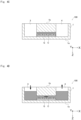
Fig. 2 is a sectional view of the microfluidic device taken along a line II-II shown inFig. 1 . -
Fig. 3 is a sectional view of the microfluidic device taken along a line III-III shown inFig. 1 . -
Fig. 4A is a sectional view for illustrating a method for using the microfluidic device shown inFig. 1 . -
Fig. 4B is a sectional view for illustrating a method for using the microfluidic device shown inFig. 1 . -
Fig. 4C is a sectional view for illustrating a method for using the microfluidic device shown inFig. 1 . -
Fig. 4D is a sectional view for illustrating a method for using the microfluidic device shown inFig. 1 . -
Fig. 5 is a sectional view for illustrating a method for using the microfluidic device shown inFig. 1 . -
Fig. 6 is a sectional view of a microfluidic device of a comparative example. -
Fig. 7 is a perspective view of a microfluidic device according to a second embodiment. -
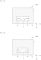
Fig. 8 is a sectional view of the microfluidic device taken along a line VIII-VIII shown inFig. 7 . -
Fig. 9 is a sectional view of the microfluidic device taken along a line IX-IX shown inFig. 7 . -
Fig. 10 is a sectional view of a microfluidic device according to another embodiment. -
Fig. 11 is a sectional view of a microfluidic device according to another embodiment. -
Fig. 12 is a sectional view of a microfluidic device according to another embodiment. -
Fig. 13 is a sectional view of a microfluidic device according to another embodiment. -
Fig. 14 is a sectional view of a microfluidic device according to another embodiment. -
Fig. 15 is a sectional view of a microfluidic device according to another embodiment. -
Fig. 16 is a sectional view of a microfluidic device according to another embodiment. -
Fig. 17 is a sectional view of a microfluidic device according to another embodiment. -
Fig. 18 is a sectional view of a microfluidic device according to another embodiment. -
Fig. 19 is a plan view of a microfluidic device according to another embodiment. -
Fig. 20 is a sectional view of the microfluidic device taken along a line XX-XX shown inFig. 19 . -
Fig. 21A is a sectional view for illustrating a method for using the microfluidic device shown inFig. 19 . -
Fig. 21B is a sectional view for illustrating a method for using the microfluidic device shown inFig. 19 . -
Fig. 21C is a sectional view for illustrating a method for using the microfluidic device shown inFig. 19 . -
Fig. 21D is a sectional view for illustrating a method for using the microfluidic device shown inFig. 19 . - A microfluidic device and a method for using the microfluidic device according to the present invention will be described with reference to the drawings. It should be noted that the drawings disclosed herein merely show schematic illustrations. Namely, the dimensional ratios on the drawings do not necessarily reflect the actual dimensional ratios, and the dimensional ratios are not necessarily the same between the drawings.
-
Fig. 1 is a perspective view of amicrofluidic device 100 according to a first embodiment. Themicrofluidic device 100 includes amain body 1 having a firstprincipal surface 1a and a secondprincipal surface 1b. The firstprincipal surface 1a and the secondprincipal surface 1b are disposed so as to face each other. - In the following description, an XYZ coordinate system is appropriately referenced in which a plane parallel to the first
principal surface 1a and the secondprincipal surface 1b is defined as an XY plane and a direction orthogonal to the XY plane is defined as a Z direction. - When it is necessary to make a distinction between positive and negative to express a direction herein, the direction is described with a positive or negative sign, such as "+X direction" or "-X direction". When it is not necessary to make a distinction between positive and negative to express a direction, the direction is simply described as "X direction". Namely, when the direction is simply described as "X direction" herein, both "+X direction" and "-X direction" are included. The same applies to a Y direction and a Z direction.
- The
main body 1 is formed in a plate shape so as to have the firstprincipal surface 1a and the secondprincipal surface 1b facing each other in the Z direction. The Z direction in the present embodiment corresponds to a "first direction". It should be noted that themicrofluidic device 100 is usually used so that the Z direction corresponds to a vertical direction, and the -Z direction corresponds to an upward direction. - As shown in
Fig. 2 , themicrofluidic device 100 includes afirst flow path 2 formed inside themain body 1. Thefirst flow path 2 extends along the XY plane between the firstprincipal surface 1a and the secondprincipal surface 1b, and specifically extends in the X direction. Both ends 2a and 2b of thefirst flow path 2 are located inside themicrofluidic device 100. - The
microfluidic device 100 includes firstflow path ports flow path port 3 is connected to the oneend 2a of thefirst flow path 2, and the firstflow path port 4 is connected to theother end 2b of thefirst flow path 2. The firstflow path port 3 has one end open to the oneend 2a of thefirst flow path 2 and another end open to the secondprincipal surface 1b. The firstflow path port 4 has one end open to theother end 2b of thefirst flow path 2 and another end open to the secondprincipal surface 1b. The firstflow path ports microfluidic device 100 and the purpose of discharging a liquid from themicrofluidic device 100. For example, the firstflow path port 3 may be used as a liquid inlet and the firstflow path port 4 may be used as a liquid outlet. - As shown in
Fig. 3 , thefirst flow path 2 of the first embodiment includes afirst space 21 and asecond space 22 adjacent to thefirst space 21 on the secondprincipal surface 1b side in the Z direction (-Z direction side). Thefirst space 21 has a rectangular cross-section in a YZ plane. Thesecond space 22 has a trapezoidal cross-section in the YZ plane. Thesecond space 22 hasside walls side walls principal surface 1b. Therefore, theside walls second space 22 allow aflow path width 2w of thefirst flow path 2 in the Y direction to increase from the firstprincipal surface 1a side toward the secondprincipal surface 1b side. That is, theside walls second space 22 in the first embodiment correspond to "enlarged parts" in the present invention. - A
virtual surface 20 formed by connecting the firstprincipal surface 1a-side end of theside wall 22a and the firstprincipal surface 1a-side end of theside wall 22b, specifically aninterface 20 between thefirst space 21 and thesecond space 22 is parallel to the firstprincipal surface 1a. - As described above, the
microfluidic device 100 according to the first embodiment includes a plate-shapedmain body 1 having a firstprincipal surface 1a and a secondprincipal surface 1b facing each other in the Z direction, afirst flow path 2 formed inside themain body 1 and extending along the XY plane between the firstprincipal surface 1a and the secondprincipal surface 1b, and firstflow path ports end first flow path 2 and another end open to the secondprincipal surface 1b. Further, thefirst flow path 2 hasside walls flow path width 2w increases from the firstprincipal surface 1a side toward the secondprincipal surface 1b side when thefirst flow path 2 is viewed in its extension direction (X direction). The function and effect of themicrofluidic device 100 will be described later in the description of a method for using themicrofluidic device 100. - Further, as described with reference to the first embodiment, the
first flow path 2 includes afirst space 21 and asecond space 22 that is adjacent to thefirst space 21 on the secondprincipal surface 1b side in the Z direction and that has a largerflow path width 2w than thefirst space 21 by theside walls - Further, as described with reference to the first embodiment, the
side walls principal surface 1a. - Further, as described with reference to the first embodiment, the
first flow path 2 hasside walls virtual surface 20 formed by connecting together the firstprincipal surface 1a-side end of theside wall 22a and the firstprincipal surface 1a-side end of theside wall 22b is parallel to the firstprincipal surface 1a. - Hereinbelow, a method for using the
microfluidic device 100 will be described in detail.Fig. 4A to Fig. 4D are sectional views schematically illustrating the method for using themicrofluidic device 100. The method for using themicrofluidic device 100 includes: a first step (shown inFig. 4A ) in which themicrofluidic device 100 is disposed so that the firstprincipal surface 1a is located on a lower side and the secondprincipal surface 1b is located on an upper side; a second step (shown inFig. 4B ) in which a sol S is injected into a region below theside walls second space 22 in thefirst flow path 2, and a third step (shown inFig. 4C ) in which cell C are seeded on a top surface of a gel G obtained by solidifying the sol S. The method for using themicrofluidic device 100 may further include a fourth step (shown inFig. 4D ) in which a culture solution is injected into a region above the gel G in thefirst flow path 2 to culture the cells C. - The sol S herein means a solution in which colloidal particles (dispersoid) are contained in a dispersion medium, and the gel G herein refers to one obtained by solidifying the sol S into a jelly-like state. In the second step shown in
Fig. 4B , a sol S is injected through the firstflow path port 3 or the firstflow path port 4. The amount of the sol S to be injected is equal to or less than an amount corresponding to the volume of thefirst space 21, preferably equal to an amount corresponding to the volume of thefirst space 21. - As shown in
Fig. 5 , the sol S injected through the firstflow path port 3 or the firstflow path port 4 remains in thefirst space 21 under the action of surface tension. Surface tension is the property of a liquid or solid to minimize its surface area as much as possible, and can quantitatively be represented as surface free energy per unit area in the unit of mJ/m2. -
Fig. 6 is a sectional view of a comparative example in which the flow path width of afirst flow path 2P in the Y direction is constant in the Z direction. When the flow path width of thefirst flow path 2P is constant in the Z direction, a sol S is in contact with the ceiling of thefirst flow path 2P when flowing into thefirst flow path 2P. When the sol S is solidified in such a state, cells C cannot be seeded on the top surface of a gel, and a culture solution cannot be perfused, either. - The reason why the sol S flows into the
first flow path 2P in such a manner as shown inFig. 6 is that a liquid (here, the sol S) flows into thefirst flow path 2P so that the total exposed surface area of the liquid (the area of the liquid-gas interface) is minimized for energetic stability. - On the other hand, in the present invention, the total surface area of the sol S at the time when the sol S remains at the level of the
interface 20 between thefirst space 21 and thesecond space 22 is smaller than that at the time when the sol S is filled beyond theinterface 20, and therefore the sol S remains at the level of theinterface 20 under the action of surface tension to be energetically stable. - When the sol S is solidified in such a state, the
second space 22 is maintained above the gel G so that cells C can be seeded on the top surface of the gel G in the third step. It should be noted that the cells C can be seeded by injecting a culture solution containing the cells C into thesecond space 22. Since theside walls principal surface 1a, the cells C can be prevented from adhering to surfaces other than the top surface of thegel 2 when the cells C are seeded. - Further, since the
second space 22 is maintained above the gel G, the cells C can be cultured by injecting a culture solution into a region above the gel G in the fourth step. The cells C after cultivation are observed through the firstprincipal surface 1a with a microscope from the outside of themicrofluidic device 100. In this regard, themicrofluidic device 100 according to the present invention is excellent in observability because the top surface of the gel G is flat and the parallel to the firstprincipal surface 1a. It should be noted that the present embodiment has been described with reference to a case where the firstprincipal surface 1a and the top surface of the gel G are parallel to each other, but when themicrofluidic device 100 has a frame surrounding the firstprincipal surface 1a, the top surface of the gel G shall be parallel to the bottom surface of the frame. - The gel G is selected from the group consisting of collagen, gelatin, hyaluronate, hyaluronan, fibrin, alginate, agarose, chitosan, chitin, cellulose, pectin, starch, laminin, fibrinogen/thrombin, fibrillin, elastin, gum, cellulose, agar, gluten, casein, albumin, vitronectin, tenascin, entactin/nidogen, glycoprotein, glycosaminoglycan, poly(acrylic acid) and derivatives thereof, poly(ethylene oxide) and copolymers thereof, poly(vinyl alcohol), polyphosphazene, Matrigel, and combinations of two or more of them.
-
Fig. 7 is a perspective view of amicrofluidic device 100A according to a second embodiment.Fig. 8 is a sectional view of themicrofluidic device 100A taken along a line VIII-VIII shown inFig. 7 , andFig. 9 is a sectional view of themicrofluidic device 100A taken along a line IX-IX shown inFig. 7 . - As shown in
Fig. 7 to Fig. 9 , thefirst flow path 2 in the second embodiment includesprojections 9 that project fromside walls projections 9 project from the central regions of both of theside walls projections 9 has a triangular cross-section in the YZ plane. - Each of the
projections 9 has alower surface 9a on the firstprincipal surface 1a side (+Z direction side) and anupper surface 9b on the secondprincipal surface 1b side (-Z direction side). Thelower surface 9a is parallel to the firstprincipal surface 1a. On the other hand, theupper surface 9b is inclined with respect to the firstprincipal surface 1a. Theupper surface 9b is inclined so as to depart from the firstprincipal surface 1a as extending from the tip of theprojection 9 toward theside wall flow path width 2w of thefirst flow path 2 in the Y direction to increase from the firstprincipal surface 1a side toward the secondprincipal surface 1b side in a region where theprojections 9 are formed. That is, theupper surfaces 9b of theprojections 9 in the second embodiment correspond to "enlarged parts" in the present invention. It should be noted that in a region where theprojections 9 are not formed, both of theside walls first flow path 2 in the Y direction are parallel to each other. - As described above, the
microfluidic device 100A according to the second embodiment includes a plate-shapedmain body 1 having a firstprincipal surface 1a and a secondprincipal surface 1b facing each other in the Z direction, afirst flow path 2 formed inside themain body 1 and extending along the XY plane between the firstprincipal surface 1a and the secondprincipal surface 1b, and firstflow path ports first flow path 2 and another end open to the secondprincipal surface 1b. Further, thefirst flow path 2 hasupper surfaces 9b of projections 9 (enlarged parts) so that aflow path width 2w increases from the firstprincipal surface 1a side toward the secondprincipal surface 1b side when thefirst flow path 2 is viewed in its extension direction (X direction). - Further, as described with reference to the second embodiment, the
upper surfaces 9b of the projections 9 (enlarged parts) are inclined with respect to the firstprincipal surface 1a. - Further, as described with reference to the second embodiment, the
first flow path 2 hasupper surfaces 9b of projections 9 (enlarged parts) on its both sides in the Y direction respectively, and avirtual surface 20 formed by connecting together the firstprincipal surface 1a-side ends of theupper surfaces 9b is parallel to the firstprincipal surface 1a. - Although the embodiments of the present invention have been described above with reference to the drawings, it should be understood that specific configurations are not limited to those of these embodiments. The scope of the present invention is indicated not only by the above description of the embodiments but also by the claims, and all changes which come within the meaning and range of equivalency of the claims are therefore intended to be embraced therein.
- The structure adopted in each of the above embodiments can be adopted in any other embodiment. Specific configurations of parts are not limited only to those in the above-described embodiments, and various modifications can be made without departing from the spirit of the present invention.
- (1) In the
microfluidic device 100 according to the first embodiment, thefirst flow path 2 is configured to include afirst space 21 and asecond space 22 that is adjacent to thefirst space 21 on the secondprincipal surface 1b side in the Z direction and that has a largerflow path width 2w than thefirst space 21 by theside walls microfluidic device 100 is not limited thereto. As in the case of amicrofluidic device 100B shown inFig. 10 , thefirst flow path 2 may include afirst space 21 and asecond space 22 that is adjacent to thefirst space 21 on the secondprincipal surface 1b side in the Z direction and that has a largerflow path width 2w than thefirst space 21 bybottom walls bottom walls second space 22 correspond to "enlarged parts" in the present invention. Thesecond space 22 has a rectangular cross-section in the YZ plane, and thebottom walls principal surface 1a. - (2) The
microfluidic device 100A according to the second embodiment is configured in such a manner that theupper surfaces 9b of theprojections 9 are inclined with respect to the firstprincipal surface 1a. However, the configuration of themicrofluidic device 100A is not limited thereto. As in the case of amicrofluidic device 100C shown inFig. 11 , theupper surfaces 9b of theprojections 9 may be parallel to the firstprincipal surface 1a. In this case, thelower surfaces 9a of theprojections 9 are inclined with respect to the firstprincipal surface 1a. - (3) The
microfluidic device 100A according to the second embodiment is configured in such a manner that thelower surfaces 9a of theprojections 9 are parallel to the firstprincipal surface 1a, and theupper surfaces 9b are inclined with respect to the firstprincipal surface 1a. However, the configuration of themicrofluidic device 100A is not limited thereto. As in the case of amicrofluidic device 100D shown inFig. 12 , thelower surfaces 9a of theprojections 9 may also be inclined with respect to the firstprincipal surface 1a similarly to theupper surfaces 9b. - (4) The
microfluidic device 100A according to the second embodiment is configured in such a manner that theprojections 9 are formed to have a triangular cross-section in the YZ plane. However, the configuration of themicrofluidic device 100A is not limited thereto. As in the case of amicrofluidic device 100E shown inFig. 13 , theprojections 9 may be formed to have a rectangular cross-section in the YZ plane. Alternatively, as in the case of amicrofluidic device 100F shown inFig. 14 , theprojections 9 may be formed in a thin film shape. In this case, each of the film-shapedprojections 9 has a thickness of, for example, 50 µm. - (5) The
microfluidic device 100A according to the second embodiment is configured in such a manner that both of theside walls first flow path 2 in the Y direction are parallel to each other in a region where theprojections 9 are not formed. However, the configuration of themicrofluidic device 100A is not limited thereto. As in the case of amicrofluidic device 100G shown inFig. 15 , a region above theprojections 9 and a region below theprojections 9 may be different in the flow path width of thefirst flow path 2. - (6) Alternatively, as in the case of a
microfluidic device 100H shown inFig. 16 , theprojections 9 may be formed to have a semicircular cross-section in the YZ plane. In this case, 1/4 circular arcs of thesemicircular projections 9 on the secondprincipal surface 1b side correspond to "enlarged parts" in the present invention. - (7) Alternatively, as in the case of a microfluidic device 100I shown in
Fig. 17 , thefirst flow path 2 may have more than twoprojections 9. In this case, two or more gel layers can be formed by, for example, first forming a gel using thelower projections 9 and then forming a gel using theupper projections 9. By changing a gel composition, density, or cells to be contained from layer to layer, various tissues or organs can be simulated, such as corneas, blood vessels (aortas, venae cavae), tracheal walls, and joints. - (8) Alternatively, as in the case of a
microfluidic device 100J shown inFig. 18 , ahole 8 may be provided which extends in the Z direction and has one end open to amiddle part 2e of thefirst flow path 2 and another end open to the secondprincipal surface 1b. Such a configuration makes it possible to culture cells seeded on the gel surface in a state where the apical side of the cells is in contact with air (air-liquid interface culture), thereby simulating an environment such as respiratory epithelial cells that interact with both liquid and air in vivo. - (9) Alternatively, as in the case of a
microfluidic device 100K shown inFig. 19 and Fig. 20 , asecond flow path 51 connected to thefirst flow path 2 and extending along the XY plane, athird flow path 52 connected to thefirst flow path 2 and extending along the XY plane, at least one secondflow path port 53 extending in the Z direction and having one end open to thesecond flow path 51 and another end open to the secondprincipal surface 1b, and at least one thirdflow path port 54 extending in the Z direction and having one end open to thethird flow path 52 and another end open to the secondprincipal surface 1b may be provided. In this embodiment, a secondprincipal surface 1b-sideupper wall surface 2t of thefirst flow path 2 is closer to the secondprincipal surface 1b than a secondprincipal surface 1b-sideupper wall surface 51t of thesecond flow path 51 and a secondprincipal surface 1b-sideupper wall surface 52 t of thethird flow path 52. Further, in this embodiment, theprojections 9 are configured to haveupper surfaces 9b corresponding to the enlarged parts as shown inFig. 9 , and thevirtual surface 20 is closer to the secondprincipal surface 1b than the secondprincipal surface 1b-sideupper wall surface 51t of thesecond flow path 51 and the secondprincipal surface 1b-sideupper wall surface 52t of thethird flow path 52. - An example of a method for using the
microfluidic device 100K shown inFig. 19 and Fig. 20 will simply be described. - First, as shown in
Fig. 21A , glycerol or thermal phase transition hydrogel G1 is injected through the secondflow path port 53. At this time, the amount of the glycerol or thermal phase transition hydrogel G1 to be injected is set so that the height of the injected glycerol or thermal phase transition hydrogel G1 is higher than theupper wall surface 51t of thesecond flow path 51 and theupper wall surface 52t of thethird flow path 52 and lower than thevirtual surface 20. - Then, as shown in
Fig. 21B , a sol S is injected through the firstflow path port 3 so as to spread on the glycerol or thermal phase transition hydrogel G1 and is then gelatinized. At this time, the sol S is injected into a region below thevirtual surface 20 in thefirst flow path 2. - Then, as shown in
Fig. 21C , the glycerol or thermal phase transition hydrogel G1 is removed through the secondflow path port 53 or the thirdflow path port 54. As a result, a gel G remains, and spaces are created above and below the gel G in thefirst flow path 2. - Then, as shown in
Fig. 21 D , cells C are seeded on the upper side of the gel G. -
- 100
- Microfluidic device
- 100A
- Microfluidic device
- 100B
- Microfluidic device
- 100C
- Microfluidic device
- 100D
- Microfluidic device
- 100E
- Microfluidic device
- 100F
- Microfluidic device
- 100G
- Microfluidic device
- 100H
- Microfluidic device
- 100I
- Microfluidic device
- 100J
- Microfluidic device
- 100K
- Microfluidic device
- 1
- Main body
- 1a
- First principal surface
- 1b
- Second principal surface
- 2
- First flow path
- 2a
- One end
- 2b
- Another end
- 2c
- Side wall
- 2d
- Side wall
- 2e
- Middle part
- 2t
- Upper wall surface
- 2w
- Flow path width
- 3
- First flow path port
- 4
- First flow path port
- 8
- Hole
- 9
- Projection
- 9a
- Lower surface of projection
- 9b
- Upper surface of projection
- 20
- Virtual surface (Interface)
- 21
- First space
- 22
- Second space
- 22a
- Side wall of second space
- 22b
- Side wall of second space
- 22c
- Bottom wall of second space
- 22d
- Bottom wall of second space
- 51
- Second flow path
- 51t
- Upper wall surface of second flow path
- 52
- Third flow path
- 52t
- Upper wall surface of third flow path
- 53
- Second flow path port
- 54
- Third flow path port
- C
- Cell
- G
- Gel
- G1
- Glycerol or thermal phase transition hydrogel
- S
- Sol
Claims (11)
- A microfluidic device comprising: a plate-shaped main body having a first principal surface and a second principal surface facing each other in a first direction; a first flow path formed inside the main body and extending along a plane between the first principal surface and the second principal surface; and a plurality of first flow path ports extending in the first direction and each having one end open to an end of the first flow path and another end open to the second principal surface, wherein
the first flow path has an enlarged part so that a flow path width increases from a first principal surface side toward a second principal surface side when the first flow path is viewed in its extension direction. - The microfluidic device according to claim 1, wherein the first flow path includes a first space and a second space that is adjacent to the first space on the second principal surface side and that has a larger flow path width than the first space by the enlarged part.
- The microfluidic device according to claim 1, whereinthe first flow path includes a projection that projects from a side wall and extends in the extension direction, andthe enlarged part corresponds to a second principal surface-side surface of the projection.
- The microfluidic device according to claim 1, wherein the enlarged part is a surface parallel to the first principal surface.
- The microfluidic device according to claim 1, wherein the enlarged part is a surface inclined with respect to the first principal surface.
- The microfluidic device according to claim 1, whereinthe first flow path has the enlarged parts on its both sides in a width direction respectively, anda virtual surface formed by connecting together first principal surface-side ends of the enlarged parts is parallel to the first principal surface or a bottom surface of a frame surrounding a periphery of the first principal surface.
- The microfluidic device according to claim 1, comprising a hole extending in the first direction and having one end open to a middle part of the first flow path and another end open to the second principal surface.
- The microfluidic device according to claim 1, comprising:a second flow path connected to the first flow path and extending along the plane;a third flow path connected to the first flow path and extending along the plane;at least one second flow path port extending in the first direction and having one end open to the second flow path and another end open to the second principal surface; andat least one third flow path port extending in the first direction and having one end open to the third flow path and another end open to the second principal surface.
- A method for using the microfluidic device according to claim 1, the method comprising:a first step in which the microfluidic device is disposed so that the first principal surface is located on a lower side and the second principal surface is located on an upper side;a second step in which a sol is injected into a region below the enlarged part in the first flow path, anda third step in which cells are seeded on a top surface of a gel obtained by solidifying the sol.
- The method for using the microfluidic device according to claim 9, comprising a fourth step in which a culture solution is injected into a region above the gel in the first flow path to culture the cells.
- The method for using the microfluidic device according to claim 9, wherein the gel is selected from the group consisting of collagen, gelatin, hyaluronate, hyaluronan, fibrin, alginate, agarose, chitosan, chitin, cellulose, pectin, starch, laminin, fibrinogen/thrombin, fibrillin, elastin, gum, cellulose, agar, gluten, casein, albumin, vitronectin, tenascin, entactin/nidogen, glycoprotein, glycosaminoglycan, poly(acrylic acid) and derivatives thereof, polyethylene oxide) and copolymers thereof, poly(vinyl alcohol), polyphosphazene, Matrigel, and combinations of two or more of them.
Applications Claiming Priority (2)
| Application Number | Priority Date | Filing Date | Title |
|---|---|---|---|
| JP2022022345A JP7875424B2 (en) | 2022-02-16 | 2022-02-16 | Microfluidic devices and methods for using microfluidic devices |
| PCT/JP2022/040586 WO2023157389A1 (en) | 2022-02-16 | 2022-10-31 | Microfluidic device and method for using microfluidic device |
Publications (2)
| Publication Number | Publication Date |
|---|---|
| EP4481032A1 true EP4481032A1 (en) | 2024-12-25 |
| EP4481032A4 EP4481032A4 (en) | 2025-04-30 |
Family
ID=87577918
Family Applications (1)
| Application Number | Title | Priority Date | Filing Date |
|---|---|---|---|
| EP22927283.6A Pending EP4481032A4 (en) | 2022-02-16 | 2022-10-31 | Microfluidic device and method for using microfluidic device |
Country Status (4)
| Country | Link |
|---|---|
| US (1) | US20250188396A1 (en) |
| EP (1) | EP4481032A4 (en) |
| JP (1) | JP7875424B2 (en) |
| WO (1) | WO2023157389A1 (en) |
Family Cites Families (6)
| Publication number | Priority date | Publication date | Assignee | Title |
|---|---|---|---|---|
| US8858682B2 (en) * | 2005-12-28 | 2014-10-14 | Shimadzu Corporation | Method for controlling pressure-difference bubble transfer |
| FR3030049B1 (en) * | 2014-12-11 | 2020-11-13 | Andrew David Griffiths | SYSTEM OF ANALYSIS AND CELL CULTURE, METHOD OF ANALYSIS AND ASSOCIATED CELL CULTURE AND METHOD OF MANUFACTURING THE ASSOCIATED CHIP |
| NL2015130B1 (en) | 2015-07-09 | 2017-02-01 | Mimetas B V | Barrier function measurements. |
| GB2591709B (en) * | 2015-12-04 | 2021-11-03 | Harvard College | Devices, methods, and compositions for restricting cell position and stabilizing cells in culture systems |
| US11680241B2 (en) * | 2018-02-08 | 2023-06-20 | University Of Florida Research Foundation, Inc. | Perfusion enabled bioreactors |
| JP7368117B2 (en) | 2019-06-14 | 2023-10-24 | 株式会社 資生堂 | Method for producing three-dimensional cultured skin and three-dimensional cultured skin obtained thereby |
-
2022
- 2022-02-16 JP JP2022022345A patent/JP7875424B2/en active Active
- 2022-10-31 US US18/838,126 patent/US20250188396A1/en active Pending
- 2022-10-31 EP EP22927283.6A patent/EP4481032A4/en active Pending
- 2022-10-31 WO PCT/JP2022/040586 patent/WO2023157389A1/en not_active Ceased
Also Published As
| Publication number | Publication date |
|---|---|
| EP4481032A4 (en) | 2025-04-30 |
| JP7875424B2 (en) | 2026-06-18 |
| JP2023119434A (en) | 2023-08-28 |
| WO2023157389A1 (en) | 2023-08-24 |
| US20250188396A1 (en) | 2025-06-12 |
Similar Documents
| Publication | Publication Date | Title |
|---|---|---|
| CN113893387B (en) | A tissue engineering scaffold assembled with cell-loaded microgel and its preparation method and application | |
| US8147562B2 (en) | Three dimensional construct for the design and fabrication of physiological fluidic networks | |
| CN218932176U (en) | Cell culture chip | |
| JP2020526216A (en) | Cell culture tank with a porous support | |
| BR112021000996A2 (en) | stacked recirculation bioreactor | |
| CN111094534A (en) | Handling Characteristics for Microcavity Cell Culture Vessels | |
| CN218459548U (en) | Micro-fluidic chip | |
| CN115386492B (en) | A microfluidic 3D bionic tooth peripheral tissue organoid chip and its construction method | |
| CN218465835U (en) | Cell culture chip | |
| US11857970B2 (en) | Cell culture vessel | |
| CN117721019A (en) | Vascularized organ chip and application thereof | |
| US20250188396A1 (en) | Microfluidic device and method for using microfluidic device | |
| CN218924720U (en) | Microfluidic chip | |
| Du et al. | Dynamics of endothelial cells migration in nature-mimicking blood vessels | |
| CN116077737A (en) | Artificial skin containing vascular structure and preparation method thereof | |
| CN119823871A (en) | Vascularized skin chip, vascularized skin model and its application | |
| CN116410863A (en) | A kind of microfluidic experiment plate and cell culture method | |
| KR20230035838A (en) | Microfluid chip for spheroid or organoid and method for producing spheroid or organoid model using the same | |
| EP4212611A1 (en) | Microfluidic device and method for using microfluidic device | |
| US20210348102A1 (en) | Cell culture device forming a three dimensional perfusion network from a patterned material upon exposure to hydrogel | |
| CN219861384U (en) | Cell culture unit and cell culture device | |
| CN112358966B (en) | A sliding microfluidic organ chip and preparation method thereof | |
| CN116496904A (en) | Cell culture unit, device, application and culture method | |
| CN116004384A (en) | Pluggable and fluxional multi-organ interconnection chip | |
| CN115747062A (en) | Automatic liquid changing culture dish |
Legal Events
| Date | Code | Title | Description |
|---|---|---|---|
| STAA | Information on the status of an ep patent application or granted ep patent |
Free format text: STATUS: THE INTERNATIONAL PUBLICATION HAS BEEN MADE |
|
| PUAI | Public reference made under article 153(3) epc to a published international application that has entered the european phase |
Free format text: ORIGINAL CODE: 0009012 |
|
| STAA | Information on the status of an ep patent application or granted ep patent |
Free format text: STATUS: REQUEST FOR EXAMINATION WAS MADE |
|
| 17P | Request for examination filed |
Effective date: 20240816 |
|
| AK | Designated contracting states |
Kind code of ref document: A1 Designated state(s): AL AT BE BG CH CY CZ DE DK EE ES FI FR GB GR HR HU IE IS IT LI LT LU LV MC ME MK MT NL NO PL PT RO RS SE SI SK SM TR |
|
| A4 | Supplementary search report drawn up and despatched |
Effective date: 20250327 |
|
| RIC1 | Information provided on ipc code assigned before grant |
Ipc: B01L 3/00 20060101ALN20250321BHEP Ipc: C12M 3/06 20060101ALI20250321BHEP Ipc: C12M 1/12 20060101ALI20250321BHEP Ipc: C12M 3/00 20060101AFI20250321BHEP |
|
| DAV | Request for validation of the european patent (deleted) | ||
| DAX | Request for extension of the european patent (deleted) | ||
| RAP3 | Party data changed (applicant data changed or rights of an application transferred) |
Owner name: USHIO DENKI KABUSHIKI KAISHA |
|
| RAP1 | Party data changed (applicant data changed or rights of an application transferred) |
Owner name: USHIO DENKI KABUSHIKI KAISHA Owner name: ZEON CORPORATION |
|
| RAP1 | Party data changed (applicant data changed or rights of an application transferred) |
Owner name: ZEON CORPORATION |