EP4480939A1 - Composite component with environmental protection - Google Patents
Composite component with environmental protection Download PDFInfo
- Publication number
- EP4480939A1 EP4480939A1 EP24184126.1A EP24184126A EP4480939A1 EP 4480939 A1 EP4480939 A1 EP 4480939A1 EP 24184126 A EP24184126 A EP 24184126A EP 4480939 A1 EP4480939 A1 EP 4480939A1
- Authority
- EP
- European Patent Office
- Prior art keywords
- ceramic
- barrier layer
- article
- matrix composite
- composite article
- Prior art date
- Legal status (The legal status is an assumption and is not a legal conclusion. Google has not performed a legal analysis and makes no representation as to the accuracy of the status listed.)
- Pending
Links
Images


Classifications
-
- C—CHEMISTRY; METALLURGY
- C04—CEMENTS; CONCRETE; ARTIFICIAL STONE; CERAMICS; REFRACTORIES
- C04B—LIME, MAGNESIA; SLAG; CEMENTS; COMPOSITIONS THEREOF, e.g. MORTARS, CONCRETE OR LIKE BUILDING MATERIALS; ARTIFICIAL STONE; CERAMICS; REFRACTORIES; TREATMENT OF NATURAL STONE
- C04B41/00—After-treatment of mortars, concrete, artificial stone or ceramics; Treatment of natural stone
- C04B41/009—After-treatment of mortars, concrete, artificial stone or ceramics; Treatment of natural stone characterised by the material treated
-
- C—CHEMISTRY; METALLURGY
- C04—CEMENTS; CONCRETE; ARTIFICIAL STONE; CERAMICS; REFRACTORIES
- C04B—LIME, MAGNESIA; SLAG; CEMENTS; COMPOSITIONS THEREOF, e.g. MORTARS, CONCRETE OR LIKE BUILDING MATERIALS; ARTIFICIAL STONE; CERAMICS; REFRACTORIES; TREATMENT OF NATURAL STONE
- C04B41/00—After-treatment of mortars, concrete, artificial stone or ceramics; Treatment of natural stone
- C04B41/45—Coating or impregnating, e.g. injection in masonry, partial coating of green or fired ceramics, organic coating compositions for adhering together two concrete elements
- C04B41/4505—Coating or impregnating, e.g. injection in masonry, partial coating of green or fired ceramics, organic coating compositions for adhering together two concrete elements characterised by the method of application
- C04B41/4523—Coating or impregnating, e.g. injection in masonry, partial coating of green or fired ceramics, organic coating compositions for adhering together two concrete elements characterised by the method of application applied from the molten state ; Thermal spraying, e.g. plasma spraying
-
- C—CHEMISTRY; METALLURGY
- C04—CEMENTS; CONCRETE; ARTIFICIAL STONE; CERAMICS; REFRACTORIES
- C04B—LIME, MAGNESIA; SLAG; CEMENTS; COMPOSITIONS THEREOF, e.g. MORTARS, CONCRETE OR LIKE BUILDING MATERIALS; ARTIFICIAL STONE; CERAMICS; REFRACTORIES; TREATMENT OF NATURAL STONE
- C04B41/00—After-treatment of mortars, concrete, artificial stone or ceramics; Treatment of natural stone
- C04B41/45—Coating or impregnating, e.g. injection in masonry, partial coating of green or fired ceramics, organic coating compositions for adhering together two concrete elements
- C04B41/4505—Coating or impregnating, e.g. injection in masonry, partial coating of green or fired ceramics, organic coating compositions for adhering together two concrete elements characterised by the method of application
- C04B41/4535—Coating or impregnating, e.g. injection in masonry, partial coating of green or fired ceramics, organic coating compositions for adhering together two concrete elements characterised by the method of application applied as a solution, emulsion, dispersion or suspension
- C04B41/4539—Coating or impregnating, e.g. injection in masonry, partial coating of green or fired ceramics, organic coating compositions for adhering together two concrete elements characterised by the method of application applied as a solution, emulsion, dispersion or suspension as a emulsion, dispersion or suspension
-
- C—CHEMISTRY; METALLURGY
- C04—CEMENTS; CONCRETE; ARTIFICIAL STONE; CERAMICS; REFRACTORIES
- C04B—LIME, MAGNESIA; SLAG; CEMENTS; COMPOSITIONS THEREOF, e.g. MORTARS, CONCRETE OR LIKE BUILDING MATERIALS; ARTIFICIAL STONE; CERAMICS; REFRACTORIES; TREATMENT OF NATURAL STONE
- C04B41/00—After-treatment of mortars, concrete, artificial stone or ceramics; Treatment of natural stone
- C04B41/45—Coating or impregnating, e.g. injection in masonry, partial coating of green or fired ceramics, organic coating compositions for adhering together two concrete elements
- C04B41/4505—Coating or impregnating, e.g. injection in masonry, partial coating of green or fired ceramics, organic coating compositions for adhering together two concrete elements characterised by the method of application
- C04B41/455—Coating or impregnating, e.g. injection in masonry, partial coating of green or fired ceramics, organic coating compositions for adhering together two concrete elements characterised by the method of application the coating or impregnating process including a chemical conversion or reaction
-
- C—CHEMISTRY; METALLURGY
- C04—CEMENTS; CONCRETE; ARTIFICIAL STONE; CERAMICS; REFRACTORIES
- C04B—LIME, MAGNESIA; SLAG; CEMENTS; COMPOSITIONS THEREOF, e.g. MORTARS, CONCRETE OR LIKE BUILDING MATERIALS; ARTIFICIAL STONE; CERAMICS; REFRACTORIES; TREATMENT OF NATURAL STONE
- C04B41/00—After-treatment of mortars, concrete, artificial stone or ceramics; Treatment of natural stone
- C04B41/80—After-treatment of mortars, concrete, artificial stone or ceramics; Treatment of natural stone of only ceramics
- C04B41/81—Coating or impregnation
-
- C—CHEMISTRY; METALLURGY
- C04—CEMENTS; CONCRETE; ARTIFICIAL STONE; CERAMICS; REFRACTORIES
- C04B—LIME, MAGNESIA; SLAG; CEMENTS; COMPOSITIONS THEREOF, e.g. MORTARS, CONCRETE OR LIKE BUILDING MATERIALS; ARTIFICIAL STONE; CERAMICS; REFRACTORIES; TREATMENT OF NATURAL STONE
- C04B41/00—After-treatment of mortars, concrete, artificial stone or ceramics; Treatment of natural stone
- C04B41/80—After-treatment of mortars, concrete, artificial stone or ceramics; Treatment of natural stone of only ceramics
- C04B41/81—Coating or impregnation
- C04B41/85—Coating or impregnation with inorganic materials
- C04B41/87—Ceramics
-
- C—CHEMISTRY; METALLURGY
- C04—CEMENTS; CONCRETE; ARTIFICIAL STONE; CERAMICS; REFRACTORIES
- C04B—LIME, MAGNESIA; SLAG; CEMENTS; COMPOSITIONS THEREOF, e.g. MORTARS, CONCRETE OR LIKE BUILDING MATERIALS; ARTIFICIAL STONE; CERAMICS; REFRACTORIES; TREATMENT OF NATURAL STONE
- C04B2235/00—Aspects relating to ceramic starting mixtures or sintered ceramic products
- C04B2235/02—Composition of constituents of the starting material or of secondary phases of the final product
- C04B2235/50—Constituents or additives of the starting mixture chosen for their shape or used because of their shape or their physical appearance
- C04B2235/52—Constituents or additives characterised by their shapes
- C04B2235/5208—Fibers
- C04B2235/5252—Fibers having a specific pre-form
-
- C—CHEMISTRY; METALLURGY
- C04—CEMENTS; CONCRETE; ARTIFICIAL STONE; CERAMICS; REFRACTORIES
- C04B—LIME, MAGNESIA; SLAG; CEMENTS; COMPOSITIONS THEREOF, e.g. MORTARS, CONCRETE OR LIKE BUILDING MATERIALS; ARTIFICIAL STONE; CERAMICS; REFRACTORIES; TREATMENT OF NATURAL STONE
- C04B2235/00—Aspects relating to ceramic starting mixtures or sintered ceramic products
- C04B2235/02—Composition of constituents of the starting material or of secondary phases of the final product
- C04B2235/50—Constituents or additives of the starting mixture chosen for their shape or used because of their shape or their physical appearance
- C04B2235/52—Constituents or additives characterised by their shapes
- C04B2235/5208—Fibers
- C04B2235/5252—Fibers having a specific pre-form
- C04B2235/5256—Two-dimensional, e.g. woven structures
-
- F—MECHANICAL ENGINEERING; LIGHTING; HEATING; WEAPONS; BLASTING
- F02—COMBUSTION ENGINES; HOT-GAS OR COMBUSTION-PRODUCT ENGINE PLANTS
- F02C—GAS-TURBINE PLANTS; AIR INTAKES FOR JET-PROPULSION PLANTS; CONTROLLING FUEL SUPPLY IN AIR-BREATHING JET-PROPULSION PLANTS
- F02C7/00—Features, components parts, details or accessories, not provided for in, or of interest apart form groups F02C1/00 - F02C6/00; Air intakes for jet-propulsion plants
-
- F—MECHANICAL ENGINEERING; LIGHTING; HEATING; WEAPONS; BLASTING
- F05—INDEXING SCHEMES RELATING TO ENGINES OR PUMPS IN VARIOUS SUBCLASSES OF CLASSES F01-F04
- F05D—INDEXING SCHEME FOR ASPECTS RELATING TO NON-POSITIVE-DISPLACEMENT MACHINES OR ENGINES, GAS-TURBINES OR JET-PROPULSION PLANTS
- F05D2230/00—Manufacture
- F05D2230/90—Coating; Surface treatment
-
- F—MECHANICAL ENGINEERING; LIGHTING; HEATING; WEAPONS; BLASTING
- F05—INDEXING SCHEMES RELATING TO ENGINES OR PUMPS IN VARIOUS SUBCLASSES OF CLASSES F01-F04
- F05D—INDEXING SCHEME FOR ASPECTS RELATING TO NON-POSITIVE-DISPLACEMENT MACHINES OR ENGINES, GAS-TURBINES OR JET-PROPULSION PLANTS
- F05D2300/00—Materials; Properties thereof
- F05D2300/60—Properties or characteristics given to material by treatment or manufacturing
- F05D2300/603—Composites; e.g. fibre-reinforced
- F05D2300/6033—Ceramic matrix composites [CMC]
Definitions
- a gas turbine engine typically includes a fan section, a compressor section, a combustor section and a turbine section. Air entering the compressor section is compressed and delivered into the combustion section where it is mixed with fuel and ignited to generate a high-energy exhaust gas flow. The high-energy exhaust gas flow expands through the turbine section to drive the compressor and the fan section.
- the compressor section typically includes low and high pressure compressors, and the turbine section includes low and high pressure turbines.
- This disclosure relates to composite articles, such as those used in gas turbine engines.
- Components such as gas turbine engine components, may be subjected to high temperatures, corrosive and oxidative conditions, and elevated stress levels.
- the component may include features that provide environmental protection.
- a ceramic matrix composite article includes ceramic-based reinforcements disposed in a ceramic-based matrix and a barrier layer present at least in part within bounds of the ceramic-based matrix of the ceramic matrix composite article.
- the barrier layer includes gettering particles.
- the barrier layer includes a top zone extending beyond the ceramic-based matrix and disposed on the surface of the ceramic matrix composite article.
- the ceramic-based reinforcements are fibers.
- the ceramic-based reinforcements are arranged in a three-dimensional weave.
- the ceramic-based reinforcements are arranged in a two-dimensional weave.
- the article includes an infiltrated (or integrated) zone in which the barrier layer is present within the bounds of the ceramic-based matrix.
- the infiltrated zone is at least about 100 microns thick.
- a method of applying a barrier layer to an article includes providing a ceramic matrix composite article including ceramic-based reinforcements disposed in a ceramic-based matrix and applying a barrier layer to the ceramic matrix composite article such that at least some of the barrier layer infiltrates into voids in the ceramic matrix composite article with a barrier layer.
- providing the ceramic matrix composite article includes providing fugitive reinforcements (such as fugitive fibers) in the ceramic matrix composite article.
- the method includes removing the fugitive reinforcements, thereby leaving behind the voids.
- the ceramic matrix composite article has a surface region having a looser weave structure compared to a weave structure in a body of the ceramic matrix composite article.
- the barrier layer is applied by slurry coating.
- the barrier layer is applied by one of melt infiltration and reactive melting.
- the barrier layer after the applying, includes a top zone extending beyond the ceramic-based matrix and disposed on the surface of the ceramic matrix composite article.
- the low speed spool 30 generally includes an inner shaft 40 that interconnects, a first (or low) pressure compressor 44 and a first (or low) pressure turbine 46.
- the inner shaft 40 is connected to the fan 42 through a speed change mechanism, which in exemplary gas turbine engine 20 is illustrated as a geared architecture 48 to drive a fan 42 at a lower speed than the low speed spool 30.
- the high speed spool 32 includes an outer shaft 50 that interconnects a second (or high) pressure compressor 52 and a second (or high) pressure turbine 54.
- a combustor 56 is arranged in exemplary gas turbine 20 between the high pressure compressor 52 and the high pressure turbine 54.
- a mid-turbine frame 57 of the engine static structure 36 may be arranged generally between the high pressure turbine 54 and the low pressure turbine 46.
- the mid-turbine frame 57 further supports bearing systems 38 in the turbine section 28.
- the inner shaft 40 and the outer shaft 50 are concentric and rotate via bearing systems 38 about the engine central longitudinal axis A which is colline
- the engine 20 in one example is a high-bypass geared aircraft engine.
- the engine 20 bypass ratio is greater than about six (6), with an example embodiment being greater than about ten (10)
- the geared architecture 48 is an epicyclic gear train, such as a planetary gear system or other gear system, with a gear reduction ratio of greater than about 2.3
- the low pressure turbine 46 has a pressure ratio that is greater than about five.
- the engine 20 bypass ratio is greater than about ten (10:1)
- the fan diameter is significantly larger than that of the low pressure compressor 44
- the low pressure turbine 46 has a pressure ratio that is greater than about five 5:1.
- Low pressure turbine 46 pressure ratio is pressure measured prior to inlet of low pressure turbine 46 as related to the pressure at the outlet of the low pressure turbine 46 prior to an exhaust nozzle.
- the geared architecture 48 may be an epicycle gear train, such as a planetary gear system or other gear system, with a gear reduction ratio of greater than about 2.3:1 and less than about 5:1. It should be understood, however, that the above parameters are only exemplary of one embodiment of a geared architecture engine and that the present invention is applicable to other gas turbine engines including direct drive turbofans. A significant amount of thrust is provided by the bypass flow B due to the high bypass ratio.
- the fan section 22 of the engine 20 is designed for a particular flight condition -- typically cruise at about 0.8 Mach and about 35,000 feet (10,668 meters).
- Low fan pressure ratio is the pressure ratio across the fan blade alone, without a Fan Exit Guide Vane (“FEGV”) system.
- the low fan pressure ratio as disclosed herein according to one non-limiting embodiment is less than about 1.45.
- “Low corrected fan tip speed” is the actual fan tip speed in ft/sec divided by an industry standard temperature correction of [(Tram °R) / (518.7 °R)]0.5.
- the "Low corrected fan tip speed” as disclosed herein according to one non-limiting embodiment is less than about 1150 ft / second (350.5 meters/second).
- the example gas turbine engine includes the fan section 22 that comprises in one non-limiting embodiment less than about 26 fan blades 42. In another non-limiting embodiment, the fan section 22 includes less than about 20 fan blades 42. Moreover, in one disclosed embodiment the low pressure turbine 46 includes no more than about 6 turbine rotors. In another non-limiting example embodiment the low pressure turbine 46 includes about 3 turbine rotors. A ratio between the number of fan blades 42 and the number of low pressure turbine rotors is between about 3.3 and about 8.6. The example low pressure turbine 46 provides the driving power to rotate the fan section 22 and therefore the relationship between the number of turbine rotors in the low pressure turbine 46 and the number of blades 42 in the fan section 22 disclose an example gas turbine engine 20 with increased power transfer efficiency.
- CMCs include, generally, ceramic-based reinforcement such as fibers or other reinforcements in a ceramic-based matrix.
- the use of CMCs for engine 20 components provide various benefits including high temperature capabilities as compared to traditional materials such as metals.
- CMC components in certain applications benefit from environmental and/or thermal protection which can be provided by a barrier layer (coating) on the component.
- a coating is applied to a CMC article after the article is formed by application methods such as slurry coating.
- Some coatings are susceptible to cracking and/or brittle fracture depending on the composition of the coating, which decreases the lifetime and effectiveness of the coating. For instance, in the case of an environmental barrier, oxidants can be introduced into the coating via cracks and more easily reach the underlying CMC article.
- some coatings are susceptible to delamination from the underlying substrate material, which can decrease its lifetime and effectives as well.
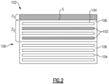
- FIG. 2 schematically illustrates a representative portion of an example CMC article 100 for the gas turbine engine that includes an integrated barrier layer 102.
- the CMC article 100 includes ceramic-based reinforcements 104, which in this example are fibers, dispersed in a ceramic-based matrix 106. It should be understood that the reinforcements 104 in any of the examples discussed here could also be tows, which are bundles of fibers.
- the article 100 can be, for example, an airfoil in the compressor section 24 or turbine section 28, a combustor liner panel in the combustor section 26, a blade outer air seal, or other component that would benefit from the examples herein.
- the integrated barrier layer 102 is used as an environmental barrier layer to protect an underlying substrate from environmental conditions, as well as thermal conditions.
- the integrated barrier layer 102 can be used as a stand-alone barrier layer or in combination with other coating layers, such as, but not limited to, ceramic-based topcoats.
- the integrated barrier layer 102 is integrated with the article 100 in that it is present at least in part within the structure of the CMC material of the article 100 (e.g., within the bounds of the matrix 106 of the CMC of the article 100).
- the integrated barrier layer 102 includes an integrated zone Zi in which barrier layer 102 is disposed within the matrix 106 and, optionally, a top zone Z T in which the barrier layer 102 extends beyond the matrix 106 and is disposed on the surface S of the CMC article 100. Because the barrier layer 102 is integrated into the CMC material of the article 100 the propensity for cracking and delamination are reduced, providing the barrier layer 102 with improved impact resistance.
- the barrier layer 102 is formed by creating or providing voids in the CMC structure of the article 100 and infiltrating the barrier layer 102 into the voids.
- the integrated zone Z I is at least about 100 microns thick.
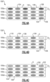
- FIG 3A schematically illustrates a CMC article 100 with three-dimensional woven fiber reinforcements 104 situated in a matrix 106, prior to application of the barrier layer 102.
- the CMC article 100 include fugitive fibers 108 near the surface S of the article 100 in what will become the integrated zone Zi.
- the use of fugitive fibers is well-known in the art and will not be described in great detail herein.
- the fugitive fibers comprise materials that can be dissolved away or burned off at relatively low temperatures, such as nylon or PVA (polyvinyl acetate).
- the fugitive fibers 108 are integrated within the CMC article 100 in the same weave pattern as the fibers 104. However, in other example fugitive fibers 108 could be incorporated into the CMC article 100 with a different weave pattern.
- Figure 3B shows the CMC article 100 with fugitive fibers 108 removed by any known method depending on the material selected for the fugitive fibers 108 and voids 110 left in place of the fugitive fibers 108.
- the removing can include heating to a temperature at which the fugitive fibers 108 burn off, which in some examples can occur during steps of manufacturing the CMC article 100 (which are well known in the art), such as during chemical vapor infiltration or other high temperature treatment of the preform.
- the removing occurs after lay-up/preforming of the CMC article 100.
- Figure 3C shows the CMC article 100 with barrier layer 102 integrated into the integrated zone Zi (e.g., wherein the barrier layer 102 infiltrates the voids 110).
- Figure 3C shows the optional top zone Z T in which the barrier layer 102 extends beyond the matrix 106 and is disposed on the surface S of the CMC article 100.
- FIG 4A schematically illustrates another example CMC article 100' with two-dimensional woven fiber reinforcements 104 situated in a matrix 106.
- the CMC article 100' comprises multiple plies 100a/100b/100c/100d of 2D woven fiber reinforcements 104 infiltrated with matrix 106.
- the outermost ply 100a comprises a combination of fugitive fibers 108 and fibers 104 of the CMC article 100.
- only one outermost ply 100a includes the fugitive fibers 108, but in other examples, there may be multiple plies that include the fugitive fibers 108 near the surface S of the CMC article 100.
- Figure 4B shows the CMC article 100' with fugitive fibers 108 removed and voids 110 left in place of the fugitive fibers 108.
- the removing can include heating to a temperature at which the fugitive fibers 108 burn off.
- Figure 4C shows the CMC article 100' with barrier layer 102 integrated into the integrated zone Zi (e.g., wherein the barrier layer 102 infiltrates the voids 110).
- Figure 4C does not show the optional top zone Z T , but one could be used as discussed above.
- CMC article 100/100' may include voids 110 in the form of porosity within the matrix 106.
- the CMC article 100/100' could be formed with graded porosity decreasing from the body of the CMC article 100/100' to its surface by various manufacturing techniques known in the art.
- the CMC article 100/100' could be provided with a surface region having a looser weave structure compared to the weave structure in the body of the CMC article 100/100'.
- the surface region which later becomes the integration zone Zi, therefore has larger spaces between adjacent fibers 104 and as a result will tend to have higher porosity after matrix 106 infiltration. Said voids 110 can be infiltrated with the barrier layer 102 as discussed above.
- the barrier layer 102 provides at least environmental protection to the CMC article 100/100'.
- the barrier layer 102 can in some examples include gettering particles dispersed in a matrix (which may be different from the matrix 106 of the CMC article 100/100').
- the gettering particles can react with oxidant particles, such as oxygen or water, that could diffuse into the barrier layer 102. In this way, the gettering particles could reduce the likelihood of those oxidant particles reaching and oxidizing the CMC article 100/100'.
- the gettering particles thus function as an oxygen and moisture diffusion barrier to limit the exposure of the underlying CMC article 100 to oxygen and/or moisture from the surrounding environment.
- the barrier layer 102 may optionally also include diffusive particles.
- the diffusive particles enhance oxidation and moisture protection by diffusion of some or all of the composition constituents to the outer surface of the barrier layer 102 and forming a sealing layer that seals the underlying CMC article 100/100' from oxygen/moisture exposure.
- the diffusive particles may include cationic metal species which can diffuse into the gettering particles to enhance oxidation stability of the gettering particle material.
- the diffusion behavior of the diffusive particles may operate to seal any microcracks that could form in the barrier layer 102. Sealing the micro-cracks could prevent oxygen from infiltrating the barrier layer 102, which further enhances the oxidation resistance of the barrier layer.
- the barrier layer 102 can be applied by any method suitable for the composition of the barrier layer 102 that enables the barrier layer 102 material to infiltrate into voids 110.
- gettering particles, and optional diffusive particles could be provided in the form of a slurry, applied to the CMC article by painting, dipping, spraying, or any suitable method, thereby infiltrating the barrier layer 102 into the voids 110 and optionally forming the top zone Z T , and then curing or sintering the barrier layer 102 as would be known in the art.
- Melt infiltration or reactive melting both of which are known in the art, could also be used to apply and infiltrate the barrier layer 102.
- melt infiltration/reactive melting are particularly well-suited for barrier layers 102 including silicates, such as rare earth silicates.
- silicates such as rare earth silicates.
- the delocalized nature of the barrier layer 102 dispersed within the voids 110 in the integrated zone Zi improves the oxidation resistance of the barrier layer 102 as compared to other coating system by providing more sites for potential neutralization of oxidants.
- the infiltration of the barrier layer 102 into the voids 110 creates an integrated zone Z I that has a lower porosity (higher density) than the body of the CMC article 100/100'.
- the lower porosity/higher density also contributes to the protective properties of the barrier layer 102 against environmental factors by reducing the propensity of oxidants to enter into the body of the CMC article 100/100' (known as "shielding").
Landscapes
- Chemical & Material Sciences (AREA)
- Engineering & Computer Science (AREA)
- Ceramic Engineering (AREA)
- Materials Engineering (AREA)
- Structural Engineering (AREA)
- Organic Chemistry (AREA)
- Dispersion Chemistry (AREA)
- Chemical Kinetics & Catalysis (AREA)
- Physics & Mathematics (AREA)
- Plasma & Fusion (AREA)
- Inorganic Chemistry (AREA)
- Turbine Rotor Nozzle Sealing (AREA)
Abstract
A ceramic matrix composite article (100) includes ceramic-based reinforcements (104) disposed in a ceramic-based matrix (106) and a barrier layer (102) present at least in part within bounds of the ceramic-based matrix (106) of the ceramic matrix composite article (100). A method of applying a barrier layer (102) to an article (100) is also disclosed.
Description
- A gas turbine engine typically includes a fan section, a compressor section, a combustor section and a turbine section. Air entering the compressor section is compressed and delivered into the combustion section where it is mixed with fuel and ignited to generate a high-energy exhaust gas flow. The high-energy exhaust gas flow expands through the turbine section to drive the compressor and the fan section. The compressor section typically includes low and high pressure compressors, and the turbine section includes low and high pressure turbines.
- This disclosure relates to composite articles, such as those used in gas turbine engines. Components, such as gas turbine engine components, may be subjected to high temperatures, corrosive and oxidative conditions, and elevated stress levels. In order to improve the thermal and/or oxidative stability, the component may include features that provide environmental protection.
- According to a first aspect of the invention, a ceramic matrix composite article includes ceramic-based reinforcements disposed in a ceramic-based matrix and a barrier layer present at least in part within bounds of the ceramic-based matrix of the ceramic matrix composite article.
- In an example of the foregoing, the barrier layer includes gettering particles.
- In a further example of any of the foregoing, the barrier layer includes a top zone extending beyond the ceramic-based matrix and disposed on the surface of the ceramic matrix composite article.
- In a further example of any of the foregoing, the ceramic-based reinforcements are fibers.
- In a further example of any of the foregoing, the ceramic-based reinforcements are arranged in a three-dimensional weave.
- In a further example of any of the foregoing, the ceramic-based reinforcements are arranged in a two-dimensional weave.
- In a further example of any of the foregoing, the article includes an infiltrated (or integrated) zone in which the barrier layer is present within the bounds of the ceramic-based matrix. The infiltrated zone is at least about 100 microns thick.
- According to another aspect of the invention, a method of applying a barrier layer to an article includes providing a ceramic matrix composite article including ceramic-based reinforcements disposed in a ceramic-based matrix and applying a barrier layer to the ceramic matrix composite article such that at least some of the barrier layer infiltrates into voids in the ceramic matrix composite article with a barrier layer.
- In a further example of the foregoing, providing the ceramic matrix composite article includes providing fugitive reinforcements (such as fugitive fibers) in the ceramic matrix composite article.
- In a further example of any of the foregoing, the method includes removing the fugitive reinforcements, thereby leaving behind the voids.
- In a further example of any of the foregoing, removing the fugitive reinforcements occurring during manufacture of the ceramic matrix composite article.
- In a further example of any of the foregoing, the ceramic matrix composite article has a surface region having a looser weave structure compared to a weave structure in a body of the ceramic matrix composite article.
- In a further example of any of the foregoing, the barrier layer is applied by slurry coating.
- In a further example of any of the foregoing, the barrier layer is applied by one of melt infiltration and reactive melting.
- In a further example of any of the foregoing, the barrier layer includes gettering particles.
- In a further example of any of the foregoing, after the applying, the barrier layer includes a top zone extending beyond the ceramic-based matrix and disposed on the surface of the ceramic matrix composite article.
- In a further example of any of the foregoing, the ceramic-based reinforcements are fibers.
- In a further example of any of the foregoing, providing the ceramic matrix composite article includes weaving the fibers into a three-dimensional weave.
- In a further example of any of the foregoing, providing the ceramic matrix composite article includes weaving the fibers into a two-dimensional weave.
- In a further example of any of the foregoing, the article includes an infiltrated (or integrated) zone in which the barrier layer is present within the bounds of the ceramic-based matrix. The infiltrated zone is at least about 100 microns thick.
-
-
Figure 1 is a schematic view of an example gas turbine engine. -
Figure 2 schematically illustrates an example article having a barrier layer. -
Figures 3A-C schematically illustrate an example article being infiltrated with the barrier layer. -
Figures 4A-C schematically illustrate another example article being infiltrated with the barrier layer. -
Figure 1 schematically illustrates agas turbine engine 20. Thegas turbine engine 20 is disclosed herein as a two-spool turbofan that generally incorporates afan section 22, acompressor section 24, acombustor section 26 and aturbine section 28. Thefan section 22 drives air along a bypass flow path B in a bypass duct defined within ahousing 15 such as a fan case or nacelle, and also drives air along a core flow path C for compression and communication into thecombustor section 26 then expansion through theturbine section 28. Although depicted as a two-spool turbofan gas turbine engine in the disclosed non-limiting embodiment, it should be understood that the concepts described herein are not limited to use with two-spool turbofans as the teachings may be applied to other types of turbine engines including three-spool architectures. - The
exemplary engine 20 generally includes alow speed spool 30 and ahigh speed spool 32 mounted for rotation about an engine central longitudinal axis A relative to an enginestatic structure 36 viaseveral bearing systems 38. It should be understood thatvarious bearing systems 38 at various locations may alternatively or additionally be provided, and the location ofbearing systems 38 may be varied as appropriate to the application. - The
low speed spool 30 generally includes aninner shaft 40 that interconnects, a first (or low)pressure compressor 44 and a first (or low)pressure turbine 46. Theinner shaft 40 is connected to thefan 42 through a speed change mechanism, which in exemplarygas turbine engine 20 is illustrated as a gearedarchitecture 48 to drive afan 42 at a lower speed than thelow speed spool 30. Thehigh speed spool 32 includes anouter shaft 50 that interconnects a second (or high)pressure compressor 52 and a second (or high)pressure turbine 54. Acombustor 56 is arranged inexemplary gas turbine 20 between thehigh pressure compressor 52 and thehigh pressure turbine 54. Amid-turbine frame 57 of the enginestatic structure 36 may be arranged generally between thehigh pressure turbine 54 and thelow pressure turbine 46. Themid-turbine frame 57 further supports bearingsystems 38 in theturbine section 28. Theinner shaft 40 and theouter shaft 50 are concentric and rotate viabearing systems 38 about the engine central longitudinal axis A which is collinear with their longitudinal axes. - The core airflow is compressed by the
low pressure compressor 44 then thehigh pressure compressor 52, mixed and burned with fuel in thecombustor 56, then expanded through thehigh pressure turbine 54 andlow pressure turbine 46. Themid-turbine frame 57 includesairfoils 59 which are in the core airflow path C. Theturbines low speed spool 30 andhigh speed spool 32 in response to the expansion. It will be appreciated that each of the positions of thefan section 22,compressor section 24,combustor section 26,turbine section 28, and fandrive gear system 48 may be varied. For example,gear system 48 may be located aft of the low pressure compressor, or aft of thecombustor section 26 or even aft ofturbine section 28, andfan 42 may be positioned forward or aft of the location ofgear system 48. - The
engine 20 in one example is a high-bypass geared aircraft engine. In a further example, theengine 20 bypass ratio is greater than about six (6), with an example embodiment being greater than about ten (10), the gearedarchitecture 48 is an epicyclic gear train, such as a planetary gear system or other gear system, with a gear reduction ratio of greater than about 2.3 and thelow pressure turbine 46 has a pressure ratio that is greater than about five. In one disclosed embodiment, theengine 20 bypass ratio is greater than about ten (10:1), the fan diameter is significantly larger than that of thelow pressure compressor 44, and thelow pressure turbine 46 has a pressure ratio that is greater than about five 5:1.Low pressure turbine 46 pressure ratio is pressure measured prior to inlet oflow pressure turbine 46 as related to the pressure at the outlet of thelow pressure turbine 46 prior to an exhaust nozzle. The gearedarchitecture 48 may be an epicycle gear train, such as a planetary gear system or other gear system, with a gear reduction ratio of greater than about 2.3:1 and less than about 5:1. It should be understood, however, that the above parameters are only exemplary of one embodiment of a geared architecture engine and that the present invention is applicable to other gas turbine engines including direct drive turbofans. A significant amount of thrust is provided by the bypass flow B due to the high bypass ratio. Thefan section 22 of theengine 20 is designed for a particular flight condition -- typically cruise at about 0.8 Mach and about 35,000 feet (10,668 meters). The flight condition of 0.8 Mach and 35,000 ft (10,668 meters), with the engine at its best fuel consumption - also known as "bucket cruise Thrust Specific Fuel Consumption ('TSFC')" - is the industry standard parameter of lbm of fuel being burned divided by lbf of thrust the engine produces at that minimum point. "Low fan pressure ratio" is the pressure ratio across the fan blade alone, without a Fan Exit Guide Vane ("FEGV") system. The low fan pressure ratio as disclosed herein according to one non-limiting embodiment is less than about 1.45. "Low corrected fan tip speed" is the actual fan tip speed in ft/sec divided by an industry standard temperature correction of [(Tram °R) / (518.7 °R)]0.5. The "Low corrected fan tip speed" as disclosed herein according to one non-limiting embodiment is less than about 1150 ft / second (350.5 meters/second). - The example gas turbine engine includes the
fan section 22 that comprises in one non-limiting embodiment less than about 26fan blades 42. In another non-limiting embodiment, thefan section 22 includes less than about 20fan blades 42. Moreover, in one disclosed embodiment thelow pressure turbine 46 includes no more than about 6 turbine rotors. In another non-limiting example embodiment thelow pressure turbine 46 includes about 3 turbine rotors. A ratio between the number offan blades 42 and the number of low pressure turbine rotors is between about 3.3 and about 8.6. The examplelow pressure turbine 46 provides the driving power to rotate thefan section 22 and therefore the relationship between the number of turbine rotors in thelow pressure turbine 46 and the number ofblades 42 in thefan section 22 disclose an examplegas turbine engine 20 with increased power transfer efficiency. - Some components of the gas turbine engine, such as blades or seals, comprise ceramic matrix composites ("CMC"). CMCs include, generally, ceramic-based reinforcement such as fibers or other reinforcements in a ceramic-based matrix. The use of CMCs for
engine 20 components provide various benefits including high temperature capabilities as compared to traditional materials such as metals. - CMC components in certain applications benefit from environmental and/or thermal protection which can be provided by a barrier layer (coating) on the component. In conventional processes a coating is applied to a CMC article after the article is formed by application methods such as slurry coating. Some coatings are susceptible to cracking and/or brittle fracture depending on the composition of the coating, which decreases the lifetime and effectiveness of the coating. For instance, in the case of an environmental barrier, oxidants can be introduced into the coating via cracks and more easily reach the underlying CMC article. Moreover, some coatings are susceptible to delamination from the underlying substrate material, which can decrease its lifetime and effectives as well.
- To that end,
Figure 2 schematically illustrates a representative portion of anexample CMC article 100 for the gas turbine engine that includes anintegrated barrier layer 102. TheCMC article 100 includes ceramic-basedreinforcements 104, which in this example are fibers, dispersed in a ceramic-basedmatrix 106. It should be understood that thereinforcements 104 in any of the examples discussed here could also be tows, which are bundles of fibers. Thearticle 100 can be, for example, an airfoil in thecompressor section 24 orturbine section 28, a combustor liner panel in thecombustor section 26, a blade outer air seal, or other component that would benefit from the examples herein. In this example, theintegrated barrier layer 102 is used as an environmental barrier layer to protect an underlying substrate from environmental conditions, as well as thermal conditions. As will be appreciated, theintegrated barrier layer 102 can be used as a stand-alone barrier layer or in combination with other coating layers, such as, but not limited to, ceramic-based topcoats. - The
integrated barrier layer 102 is integrated with thearticle 100 in that it is present at least in part within the structure of the CMC material of the article 100 (e.g., within the bounds of thematrix 106 of the CMC of the article 100). In general, theintegrated barrier layer 102 includes an integrated zone Zi in whichbarrier layer 102 is disposed within thematrix 106 and, optionally, a top zone ZT in which thebarrier layer 102 extends beyond thematrix 106 and is disposed on the surface S of theCMC article 100. Because thebarrier layer 102 is integrated into the CMC material of thearticle 100 the propensity for cracking and delamination are reduced, providing thebarrier layer 102 with improved impact resistance. As will be discussed in detail herein, in general, thebarrier layer 102 is formed by creating or providing voids in the CMC structure of thearticle 100 and infiltrating thebarrier layer 102 into the voids. - In a particular example, the integrated zone ZI is at least about 100 microns thick.
-
Figure 3A schematically illustrates aCMC article 100 with three-dimensionalwoven fiber reinforcements 104 situated in amatrix 106, prior to application of thebarrier layer 102. In the view ofFigure 3A (and Figures 3B-C ), a single fiber stack is shown. TheCMC article 100 includefugitive fibers 108 near the surface S of thearticle 100 in what will become the integrated zone Zi. The use of fugitive fibers is well-known in the art and will not be described in great detail herein. In general, the fugitive fibers comprise materials that can be dissolved away or burned off at relatively low temperatures, such as nylon or PVA (polyvinyl acetate). In the example ofFigure 3A thefugitive fibers 108 are integrated within theCMC article 100 in the same weave pattern as thefibers 104. However, in other examplefugitive fibers 108 could be incorporated into theCMC article 100 with a different weave pattern. -
Figure 3B shows theCMC article 100 withfugitive fibers 108 removed by any known method depending on the material selected for thefugitive fibers 108 andvoids 110 left in place of thefugitive fibers 108. For instance, the removing can include heating to a temperature at which thefugitive fibers 108 burn off, which in some examples can occur during steps of manufacturing the CMC article 100 (which are well known in the art), such as during chemical vapor infiltration or other high temperature treatment of the preform. In general, the removing occurs after lay-up/preforming of theCMC article 100. -
Figure 3C shows theCMC article 100 withbarrier layer 102 integrated into the integrated zone Zi (e.g., wherein thebarrier layer 102 infiltrates the voids 110). In addition,Figure 3C shows the optional top zone ZT in which thebarrier layer 102 extends beyond thematrix 106 and is disposed on the surface S of theCMC article 100. -
Figure 4A schematically illustrates another example CMC article 100' with two-dimensionalwoven fiber reinforcements 104 situated in amatrix 106. In the view ofFigures 4A-C , only out-of-plane reinforcements 104 are shown. In this example, the CMC article 100' comprisesmultiple plies 100a/100b/100c/100d of 2D wovenfiber reinforcements 104 infiltrated withmatrix 106. Theoutermost ply 100a comprises a combination offugitive fibers 108 andfibers 104 of theCMC article 100. Moreover, in this example only oneoutermost ply 100a includes thefugitive fibers 108, but in other examples, there may be multiple plies that include thefugitive fibers 108 near the surface S of theCMC article 100. -
Figure 4B shows the CMC article 100' withfugitive fibers 108 removed andvoids 110 left in place of thefugitive fibers 108. For instance, the removing can include heating to a temperature at which thefugitive fibers 108 burn off. -
Figure 4C shows the CMC article 100' withbarrier layer 102 integrated into the integrated zone Zi (e.g., wherein thebarrier layer 102 infiltrates the voids 110).Figure 4C does not show the optional top zone ZT, but one could be used as discussed above. - Though in the examples discussed above
voids 110 are created by removingfugitive fibers 108, it should be understood that in other examplesfugitive fibers 108 may not be used. Instead,CMC article 100/100' may includevoids 110 in the form of porosity within thematrix 106. TheCMC article 100/100' could be formed with graded porosity decreasing from the body of theCMC article 100/100' to its surface by various manufacturing techniques known in the art. For instance, theCMC article 100/100' could be provided with a surface region having a looser weave structure compared to the weave structure in the body of theCMC article 100/100'. The surface region, which later becomes the integration zone Zi, therefore has larger spaces betweenadjacent fibers 104 and as a result will tend to have higher porosity aftermatrix 106 infiltration. Saidvoids 110 can be infiltrated with thebarrier layer 102 as discussed above. - In a particular example, the
barrier layer 102 provides at least environmental protection to theCMC article 100/100'. In that respect, thebarrier layer 102 can in some examples include gettering particles dispersed in a matrix (which may be different from thematrix 106 of theCMC article 100/100'). The gettering particles can react with oxidant particles, such as oxygen or water, that could diffuse into thebarrier layer 102. In this way, the gettering particles could reduce the likelihood of those oxidant particles reaching and oxidizing theCMC article 100/100'. The gettering particles thus function as an oxygen and moisture diffusion barrier to limit the exposure of theunderlying CMC article 100 to oxygen and/or moisture from the surrounding environment. Thebarrier layer 102 may optionally also include diffusive particles. Without being bound by any particular theory, the diffusive particles enhance oxidation and moisture protection by diffusion of some or all of the composition constituents to the outer surface of thebarrier layer 102 and forming a sealing layer that seals theunderlying CMC article 100/100' from oxygen/moisture exposure. Additionally, the diffusive particles may include cationic metal species which can diffuse into the gettering particles to enhance oxidation stability of the gettering particle material. Further, the diffusion behavior of the diffusive particles may operate to seal any microcracks that could form in thebarrier layer 102. Sealing the micro-cracks could prevent oxygen from infiltrating thebarrier layer 102, which further enhances the oxidation resistance of the barrier layer. - The
barrier layer 102 can be applied by any method suitable for the composition of thebarrier layer 102 that enables thebarrier layer 102 material to infiltrate intovoids 110. For instance for theexample barrier layer 102 discussed above the matrix material, gettering particles, and optional diffusive particles could be provided in the form of a slurry, applied to the CMC article by painting, dipping, spraying, or any suitable method, thereby infiltrating thebarrier layer 102 into thevoids 110 and optionally forming the top zone ZT, and then curing or sintering thebarrier layer 102 as would be known in the art. Melt infiltration or reactive melting, both of which are known in the art, could also be used to apply and infiltrate thebarrier layer 102. In particular melt infiltration/reactive melting are particularly well-suited forbarrier layers 102 including silicates, such as rare earth silicates. In this particular example the delocalized nature of thebarrier layer 102 dispersed within thevoids 110 in the integrated zone Zi improves the oxidation resistance of thebarrier layer 102 as compared to other coating system by providing more sites for potential neutralization of oxidants. - The infiltration of the
barrier layer 102 into thevoids 110 creates an integrated zone ZI that has a lower porosity (higher density) than the body of theCMC article 100/100'. The lower porosity/higher density also contributes to the protective properties of thebarrier layer 102 against environmental factors by reducing the propensity of oxidants to enter into the body of theCMC article 100/100' (known as "shielding"). - As used herein, the term "about" and "approximately" have the typical meanings in the art, however in a particular example "about" and "approximately" can mean deviations of up to 10% of the values described herein.
- Although the different examples are illustrated as having specific components, the examples of this disclosure are not limited to those particular combinations. It is possible to use some of the components or features from any of the embodiments in combination with features or components from any of the other embodiments.
- The foregoing description shall be interpreted as illustrative and not in any limiting sense. A worker of ordinary skill in the art would understand that certain modifications could come within the scope of this disclosure. For these reasons, the following claims should be studied to determine the true scope and content of this disclosure.
Claims (15)
- A ceramic matrix composite article (100) comprising:ceramic-based reinforcements (104) disposed in a ceramic-based matrix (106); anda barrier layer (102) present at least in part within bounds of the ceramic-based matrix (106).
- The article (100) of claim 1, wherein the barrier layer (102) includes a top zone (ZT) extending beyond the ceramic-based matrix (106) and disposed on the surface (S) of the ceramic matrix composite article (100).
- A method of applying a barrier layer (102) to an article (100), comprising:providing a ceramic matrix composite article (100) including ceramic-based reinforcements (104) disposed in a ceramic-based matrix (106); andapplying a barrier layer (102) to the ceramic matrix composite article (100) such that at least some of the barrier layer (102) infiltrates into voids (110) in the ceramic matrix composite article (100).
- The method of claim 3, wherein providing the ceramic matrix composite article (100) includes providing fugitive reinforcements (108) in the ceramic matrix composite article (100).
- The method of claim 4, further comprising removing the fugitive reinforcements (108), thereby leaving behind the voids (110).
- The method of claim 5, wherein removing the fugitive reinforcements (108) occurs during manufacture of the ceramic matrix composite article (100).
- The method of any of claims 3 to 6, wherein the ceramic matrix composite article (100) has a surface region having a looser weave structure compared to a weave structure in a body of the ceramic matrix composite article (100).
- The method of any of claims 3 to 7, wherein the barrier layer (102) is applied by slurry coating.
- The method of any of claims 3 to 7, wherein the barrier layer (102) is applied by one of melt infiltration and reactive melting.
- The article or method of any preceding claim, wherein the barrier layer (102) includes gettering particles.
- The method of any of claims 8 to 10, wherein after the applying, the barrier layer (102) includes a top zone (ZT) extending beyond the ceramic-based matrix (106) and disposed on the surface of the ceramic matrix composite article (100).
- The article or method of any preceding claim, wherein the ceramic-based reinforcements (104) are fibers, and optionally wherein providing the ceramic matrix composite article (100) includes weaving the fibers (104) into:a three-dimensional weave; ora two-dimensional weave.
- The article (100) of claim 12, wherein the ceramic-based reinforcements (104) are arranged in a three-dimensional weave.
- The article (100) of claim 12, wherein the ceramic-based reinforcements (104) are arranged in a two-dimensional weave.
- The article or method of any preceding claim, wherein the article (100) includes an infiltrated zone (Zi) in which the barrier layer (102) is present within the bounds of the ceramic-based matrix (106), and the infiltrated zone (ZI) is at least about 100 microns thick.
Applications Claiming Priority (1)
| Application Number | Priority Date | Filing Date | Title |
|---|---|---|---|
| US18/213,665 US12441665B2 (en) | 2023-06-23 | 2023-06-23 | Composite component with environmental protection |
Publications (1)
| Publication Number | Publication Date |
|---|---|
| EP4480939A1 true EP4480939A1 (en) | 2024-12-25 |
Family
ID=91664641
Family Applications (1)
| Application Number | Title | Priority Date | Filing Date |
|---|---|---|---|
| EP24184126.1A Pending EP4480939A1 (en) | 2023-06-23 | 2024-06-24 | Composite component with environmental protection |
Country Status (2)
| Country | Link |
|---|---|
| US (2) | US12441665B2 (en) |
| EP (1) | EP4480939A1 (en) |
Citations (5)
| Publication number | Priority date | Publication date | Assignee | Title |
|---|---|---|---|---|
| JP2008247722A (en) * | 2007-03-30 | 2008-10-16 | Ihi Corp | Ceramic-based composite member and method for manufacturing ceramic-based composite member |
| US7641941B2 (en) * | 2003-04-22 | 2010-01-05 | Goodrich Corporation | Oxidation inhibition of carbon-carbon composites |
| US20180194695A1 (en) * | 2017-01-06 | 2018-07-12 | United Technologies Corporation | Method to fabricate high temperature composite with integrated barrier coating |
| US20180305264A1 (en) * | 2011-03-02 | 2018-10-25 | Applied Thin Films Inc. | Protective Internal Coatings for Porous Substrates |
| EP3904314A1 (en) * | 2020-04-27 | 2021-11-03 | Raytheon Technologies Corporation | Environmental barrier coating |
Family Cites Families (8)
| Publication number | Priority date | Publication date | Assignee | Title |
|---|---|---|---|---|
| US10093586B2 (en) * | 2015-02-26 | 2018-10-09 | General Electric Company | Ceramic matrix composite articles and methods for forming same |
| US10024175B2 (en) | 2015-05-26 | 2018-07-17 | Rolls-Royce Corporation | Cooling holes manufactured with EBC in place |
| EP3141631B1 (en) | 2015-09-10 | 2018-03-14 | Rolls-Royce High Temperature Composites Inc | Applying silicon metal-containing bond layer to ceramic or ceramic matrix composite substrates |
| US20170081250A1 (en) * | 2015-09-17 | 2017-03-23 | Siemens Energy, Inc. | Method of forming a thermal barrier coating having a porosity architecture using additive manufacturing |
| US20190323112A1 (en) * | 2018-04-23 | 2019-10-24 | Rolls-Royce High Temperature Composites, Inc. | Composite bond coats |
| US20210198160A1 (en) | 2018-12-20 | 2021-07-01 | Rolls-Royce High Temperature Composites, Inc. | Dense multi-phase bond coat |
| US12024473B2 (en) * | 2021-06-04 | 2024-07-02 | Rtx Corporation | Through thickness reinforcement |
| US20230312425A1 (en) * | 2022-04-01 | 2023-10-05 | Raytheon Technologies Corporation | Ceramic matrix composite component and method of making the same |
-
2023
- 2023-06-23 US US18/213,665 patent/US12441665B2/en active Active
-
2024
- 2024-06-24 EP EP24184126.1A patent/EP4480939A1/en active Pending
-
2025
- 2025-08-20 US US19/304,728 patent/US20250388516A1/en active Pending
Patent Citations (5)
| Publication number | Priority date | Publication date | Assignee | Title |
|---|---|---|---|---|
| US7641941B2 (en) * | 2003-04-22 | 2010-01-05 | Goodrich Corporation | Oxidation inhibition of carbon-carbon composites |
| JP2008247722A (en) * | 2007-03-30 | 2008-10-16 | Ihi Corp | Ceramic-based composite member and method for manufacturing ceramic-based composite member |
| US20180305264A1 (en) * | 2011-03-02 | 2018-10-25 | Applied Thin Films Inc. | Protective Internal Coatings for Porous Substrates |
| US20180194695A1 (en) * | 2017-01-06 | 2018-07-12 | United Technologies Corporation | Method to fabricate high temperature composite with integrated barrier coating |
| EP3904314A1 (en) * | 2020-04-27 | 2021-11-03 | Raytheon Technologies Corporation | Environmental barrier coating |
Also Published As
| Publication number | Publication date |
|---|---|
| US20250388516A1 (en) | 2025-12-25 |
| US20240425423A1 (en) | 2024-12-26 |
| US12441665B2 (en) | 2025-10-14 |
Similar Documents
| Publication | Publication Date | Title |
|---|---|---|
| US12221393B2 (en) | Environmental barrier coating | |
| EP4219910B1 (en) | Cmc honeycomb base for abradable coating on cmc boas | |
| US11919819B2 (en) | Ceramic matrix composite with interfacial coating system | |
| US20210332709A1 (en) | Environmental barrier coating and method of applying an environmental barrier coating | |
| EP3838871A1 (en) | Environmental barrier coating | |
| EP4480939A1 (en) | Composite component with environmental protection | |
| EP4375264A1 (en) | Environmental barrier coating with thermal resistance | |
| EP3885534B1 (en) | Airfoil with buffer layer to absorb thermal mismatch | |
| EP4253601A1 (en) | Environmental barrier coating | |
| EP4317109A1 (en) | Ceramic matrix composite article and method of making the same | |
| US12503953B2 (en) | Ceramic matrix composite component with coating | |
| EP4628705A1 (en) | Blade outer air seal, gas turbine engine and method of protecting a blade outer air seal | |
| US12594579B2 (en) | Environmental barrier coating and method of repairing the same | |
| US20240141997A1 (en) | Seal with coating | |
| US12359575B2 (en) | Machinable coating with thermal protection | |
| US11976571B1 (en) | Machinable coating with thermal protection |
Legal Events
| Date | Code | Title | Description |
|---|---|---|---|
| PUAI | Public reference made under article 153(3) epc to a published international application that has entered the european phase |
Free format text: ORIGINAL CODE: 0009012 |
|
| STAA | Information on the status of an ep patent application or granted ep patent |
Free format text: STATUS: THE APPLICATION HAS BEEN PUBLISHED |
|
| AK | Designated contracting states |
Kind code of ref document: A1 Designated state(s): AL AT BE BG CH CY CZ DE DK EE ES FI FR GB GR HR HU IE IS IT LI LT LU LV MC ME MK MT NL NO PL PT RO RS SE SI SK SM TR |
|
| STAA | Information on the status of an ep patent application or granted ep patent |
Free format text: STATUS: REQUEST FOR EXAMINATION WAS MADE |
|
| 17P | Request for examination filed |
Effective date: 20250624 |