EP4480925A1 - Verfahren und vorrichtung zur hydrothermalen behandlung von kohlenstoffhaltigem material - Google Patents
Verfahren und vorrichtung zur hydrothermalen behandlung von kohlenstoffhaltigem material Download PDFInfo
- Publication number
- EP4480925A1 EP4480925A1 EP24180675.1A EP24180675A EP4480925A1 EP 4480925 A1 EP4480925 A1 EP 4480925A1 EP 24180675 A EP24180675 A EP 24180675A EP 4480925 A1 EP4480925 A1 EP 4480925A1
- Authority
- EP
- European Patent Office
- Prior art keywords
- aqueous fraction
- cell
- fraction
- reactor
- feedstock
- Prior art date
- Legal status (The legal status is an assumption and is not a legal conclusion. Google has not performed a legal analysis and makes no representation as to the accuracy of the status listed.)
- Pending
Links
Images


Classifications
-
- C—CHEMISTRY; METALLURGY
- C02—TREATMENT OF WATER, WASTE WATER, SEWAGE, OR SLUDGE
- C02F—TREATMENT OF WATER, WASTE WATER, SEWAGE, OR SLUDGE
- C02F11/00—Treatment of sludge; Devices therefor
- C02F11/06—Treatment of sludge; Devices therefor by oxidation
- C02F11/08—Wet air oxidation
- C02F11/086—Wet air oxidation in the supercritical state
-
- B—PERFORMING OPERATIONS; TRANSPORTING
- B09—DISPOSAL OF SOLID WASTE; RECLAMATION OF CONTAMINATED SOIL
- B09B—DISPOSAL OF SOLID WASTE NOT OTHERWISE PROVIDED FOR
- B09B3/00—Destroying solid waste or transforming solid waste into something useful or harmless
- B09B3/40—Destroying solid waste or transforming solid waste into something useful or harmless involving thermal treatment, e.g. evaporation
-
- C—CHEMISTRY; METALLURGY
- C02—TREATMENT OF WATER, WASTE WATER, SEWAGE, OR SLUDGE
- C02F—TREATMENT OF WATER, WASTE WATER, SEWAGE, OR SLUDGE
- C02F1/00—Treatment of water, waste water, or sewage
- C02F1/46—Treatment of water, waste water, or sewage by electrochemical methods
- C02F1/461—Treatment of water, waste water, or sewage by electrochemical methods by electrolysis
- C02F1/467—Treatment of water, waste water, or sewage by electrochemical methods by electrolysis by electrochemical disinfection; by electrooxydation or by electroreduction
- C02F1/4672—Treatment of water, waste water, or sewage by electrochemical methods by electrolysis by electrochemical disinfection; by electrooxydation or by electroreduction by electrooxydation
- C02F1/4674—Treatment of water, waste water, or sewage by electrochemical methods by electrolysis by electrochemical disinfection; by electrooxydation or by electroreduction by electrooxydation with halogen or compound of halogens, e.g. chlorine, bromine
-
- C—CHEMISTRY; METALLURGY
- C02—TREATMENT OF WATER, WASTE WATER, SEWAGE, OR SLUDGE
- C02F—TREATMENT OF WATER, WASTE WATER, SEWAGE, OR SLUDGE
- C02F1/00—Treatment of water, waste water, or sewage
- C02F1/46—Treatment of water, waste water, or sewage by electrochemical methods
- C02F1/469—Treatment of water, waste water, or sewage by electrochemical methods by electrochemical separation, e.g. by electro-osmosis, electrodialysis, electrophoresis
- C02F1/4693—Treatment of water, waste water, or sewage by electrochemical methods by electrochemical separation, e.g. by electro-osmosis, electrodialysis, electrophoresis electrodialysis
-
- C—CHEMISTRY; METALLURGY
- C10—PETROLEUM, GAS OR COKE INDUSTRIES; TECHNICAL GASES CONTAINING CARBON MONOXIDE; FUELS; LUBRICANTS; PEAT
- C10G—CRACKING HYDROCARBON OILS; PRODUCTION OF LIQUID HYDROCARBON MIXTURES, e.g. BY DESTRUCTIVE HYDROGENATION, OLIGOMERISATION, POLYMERISATION; RECOVERY OF HYDROCARBON OILS FROM OIL-SHALE, OIL-SAND, OR GASES; REFINING MIXTURES MAINLY CONSISTING OF HYDROCARBONS; REFORMING OF NAPHTHA; MINERAL WAXES
- C10G1/00—Production of liquid hydrocarbon mixtures from oil-shale, oil-sand, or non-melting solid carbonaceous or similar materials, e.g. wood, coal
- C10G1/004—Inhibiting of corrosion
-
- C—CHEMISTRY; METALLURGY
- C10—PETROLEUM, GAS OR COKE INDUSTRIES; TECHNICAL GASES CONTAINING CARBON MONOXIDE; FUELS; LUBRICANTS; PEAT
- C10G—CRACKING HYDROCARBON OILS; PRODUCTION OF LIQUID HYDROCARBON MIXTURES, e.g. BY DESTRUCTIVE HYDROGENATION, OLIGOMERISATION, POLYMERISATION; RECOVERY OF HYDROCARBON OILS FROM OIL-SHALE, OIL-SAND, OR GASES; REFINING MIXTURES MAINLY CONSISTING OF HYDROCARBONS; REFORMING OF NAPHTHA; MINERAL WAXES
- C10G1/00—Production of liquid hydrocarbon mixtures from oil-shale, oil-sand, or non-melting solid carbonaceous or similar materials, e.g. wood, coal
- C10G1/10—Production of liquid hydrocarbon mixtures from oil-shale, oil-sand, or non-melting solid carbonaceous or similar materials, e.g. wood, coal from rubber or rubber waste
-
- C—CHEMISTRY; METALLURGY
- C10—PETROLEUM, GAS OR COKE INDUSTRIES; TECHNICAL GASES CONTAINING CARBON MONOXIDE; FUELS; LUBRICANTS; PEAT
- C10G—CRACKING HYDROCARBON OILS; PRODUCTION OF LIQUID HYDROCARBON MIXTURES, e.g. BY DESTRUCTIVE HYDROGENATION, OLIGOMERISATION, POLYMERISATION; RECOVERY OF HYDROCARBON OILS FROM OIL-SHALE, OIL-SAND, OR GASES; REFINING MIXTURES MAINLY CONSISTING OF HYDROCARBONS; REFORMING OF NAPHTHA; MINERAL WAXES
- C10G3/00—Production of liquid hydrocarbon mixtures from oxygen-containing organic materials, e.g. fatty oils, fatty acids
- C10G3/40—Thermal non-catalytic treatment
-
- C—CHEMISTRY; METALLURGY
- C10—PETROLEUM, GAS OR COKE INDUSTRIES; TECHNICAL GASES CONTAINING CARBON MONOXIDE; FUELS; LUBRICANTS; PEAT
- C10G—CRACKING HYDROCARBON OILS; PRODUCTION OF LIQUID HYDROCARBON MIXTURES, e.g. BY DESTRUCTIVE HYDROGENATION, OLIGOMERISATION, POLYMERISATION; RECOVERY OF HYDROCARBON OILS FROM OIL-SHALE, OIL-SAND, OR GASES; REFINING MIXTURES MAINLY CONSISTING OF HYDROCARBONS; REFORMING OF NAPHTHA; MINERAL WAXES
- C10G3/00—Production of liquid hydrocarbon mixtures from oxygen-containing organic materials, e.g. fatty oils, fatty acids
- C10G3/42—Catalytic treatment
-
- C—CHEMISTRY; METALLURGY
- C25—ELECTROLYTIC OR ELECTROPHORETIC PROCESSES; APPARATUS THEREFOR
- C25B—ELECTROLYTIC OR ELECTROPHORETIC PROCESSES FOR THE PRODUCTION OF COMPOUNDS OR NON-METALS; APPARATUS THEREFOR
- C25B1/00—Electrolytic production of inorganic compounds or non-metals
-
- C—CHEMISTRY; METALLURGY
- C25—ELECTROLYTIC OR ELECTROPHORETIC PROCESSES; APPARATUS THEREFOR
- C25B—ELECTROLYTIC OR ELECTROPHORETIC PROCESSES FOR THE PRODUCTION OF COMPOUNDS OR NON-METALS; APPARATUS THEREFOR
- C25B1/00—Electrolytic production of inorganic compounds or non-metals
- C25B1/01—Products
- C25B1/02—Hydrogen or oxygen
- C25B1/04—Hydrogen or oxygen by electrolysis of water
-
- C—CHEMISTRY; METALLURGY
- C25—ELECTROLYTIC OR ELECTROPHORETIC PROCESSES; APPARATUS THEREFOR
- C25B—ELECTROLYTIC OR ELECTROPHORETIC PROCESSES FOR THE PRODUCTION OF COMPOUNDS OR NON-METALS; APPARATUS THEREFOR
- C25B1/00—Electrolytic production of inorganic compounds or non-metals
- C25B1/01—Products
- C25B1/24—Halogens or compounds thereof
- C25B1/26—Chlorine; Compounds thereof
-
- C—CHEMISTRY; METALLURGY
- C25—ELECTROLYTIC OR ELECTROPHORETIC PROCESSES; APPARATUS THEREFOR
- C25B—ELECTROLYTIC OR ELECTROPHORETIC PROCESSES FOR THE PRODUCTION OF COMPOUNDS OR NON-METALS; APPARATUS THEREFOR
- C25B15/00—Operating or servicing cells
- C25B15/02—Process control or regulation
-
- C—CHEMISTRY; METALLURGY
- C25—ELECTROLYTIC OR ELECTROPHORETIC PROCESSES; APPARATUS THEREFOR
- C25B—ELECTROLYTIC OR ELECTROPHORETIC PROCESSES FOR THE PRODUCTION OF COMPOUNDS OR NON-METALS; APPARATUS THEREFOR
- C25B15/00—Operating or servicing cells
- C25B15/08—Supplying or removing reactants or electrolytes; Regeneration of electrolytes
- C25B15/081—Supplying products to non-electrochemical reactors that are combined with the electrochemical cell, e.g. Sabatier reactor
-
- B—PERFORMING OPERATIONS; TRANSPORTING
- B09—DISPOSAL OF SOLID WASTE; RECLAMATION OF CONTAMINATED SOIL
- B09B—DISPOSAL OF SOLID WASTE NOT OTHERWISE PROVIDED FOR
- B09B2101/00—Type of solid waste
- B09B2101/25—Non-industrial waste, e.g. household waste
-
- B—PERFORMING OPERATIONS; TRANSPORTING
- B09—DISPOSAL OF SOLID WASTE; RECLAMATION OF CONTAMINATED SOIL
- B09B—DISPOSAL OF SOLID WASTE NOT OTHERWISE PROVIDED FOR
- B09B2101/00—Type of solid waste
- B09B2101/70—Kitchen refuse; Food waste
-
- B—PERFORMING OPERATIONS; TRANSPORTING
- B09—DISPOSAL OF SOLID WASTE; RECLAMATION OF CONTAMINATED SOIL
- B09B—DISPOSAL OF SOLID WASTE NOT OTHERWISE PROVIDED FOR
- B09B2101/00—Type of solid waste
- B09B2101/75—Plastic waste
-
- B—PERFORMING OPERATIONS; TRANSPORTING
- B09—DISPOSAL OF SOLID WASTE; RECLAMATION OF CONTAMINATED SOIL
- B09B—DISPOSAL OF SOLID WASTE NOT OTHERWISE PROVIDED FOR
- B09B2101/00—Type of solid waste
- B09B2101/85—Paper; Wood; Fabrics, e.g. cloths
-
- C—CHEMISTRY; METALLURGY
- C02—TREATMENT OF WATER, WASTE WATER, SEWAGE, OR SLUDGE
- C02F—TREATMENT OF WATER, WASTE WATER, SEWAGE, OR SLUDGE
- C02F1/00—Treatment of water, waste water, or sewage
- C02F1/46—Treatment of water, waste water, or sewage by electrochemical methods
- C02F1/461—Treatment of water, waste water, or sewage by electrochemical methods by electrolysis
- C02F1/46104—Devices therefor; Their operating or servicing
- C02F1/46109—Electrodes
- C02F2001/46133—Electrodes characterised by the material
- C02F2001/46138—Electrodes comprising a substrate and a coating
- C02F2001/46142—Catalytic coating
-
- C—CHEMISTRY; METALLURGY
- C02—TREATMENT OF WATER, WASTE WATER, SEWAGE, OR SLUDGE
- C02F—TREATMENT OF WATER, WASTE WATER, SEWAGE, OR SLUDGE
- C02F1/00—Treatment of water, waste water, or sewage
- C02F1/46—Treatment of water, waste water, or sewage by electrochemical methods
- C02F1/461—Treatment of water, waste water, or sewage by electrochemical methods by electrolysis
- C02F1/46104—Devices therefor; Their operating or servicing
- C02F1/46109—Electrodes
- C02F2001/46133—Electrodes characterised by the material
- C02F2001/46138—Electrodes comprising a substrate and a coating
- C02F2001/46147—Diamond coating
-
- C—CHEMISTRY; METALLURGY
- C02—TREATMENT OF WATER, WASTE WATER, SEWAGE, OR SLUDGE
- C02F—TREATMENT OF WATER, WASTE WATER, SEWAGE, OR SLUDGE
- C02F2201/00—Apparatus for treatment of water, waste water or sewage
- C02F2201/46—Apparatus for electrochemical processes
- C02F2201/461—Electrolysis apparatus
- C02F2201/46105—Details relating to the electrolytic devices
- C02F2201/46115—Electrolytic cell with membranes or diaphragms
-
- C—CHEMISTRY; METALLURGY
- C10—PETROLEUM, GAS OR COKE INDUSTRIES; TECHNICAL GASES CONTAINING CARBON MONOXIDE; FUELS; LUBRICANTS; PEAT
- C10L—FUELS NOT OTHERWISE PROVIDED FOR; NATURAL GAS; SYNTHETIC NATURAL GAS OBTAINED BY PROCESSES NOT COVERED BY SUBCLASSES C10G OR C10K; LIQUIFIED PETROLEUM GAS; USE OF ADDITIVES TO FUELS OR FIRES; FIRE-LIGHTERS
- C10L9/00—Treating solid fuels to improve their combustion
- C10L9/08—Treating solid fuels to improve their combustion by heat treatments, e.g. calcining
- C10L9/086—Hydrothermal carbonization
Definitions
- the invention relates to methods and devices for hydrothermally treating carbon-containing material.
- the invention relates to methods and devices for hydrothermally treating carbon-containing material such that consumption of water is reduced.
- the invention relates electrochemical purification of industrial wastewaters.
- the invention relates electrochemical purification of wastewater of an industrial process for the purpose of recycling the water into the same industrial process.
- Carbon-containing material such as biomass, e.g. lignocellulosic material, refuse-derived fuel (RDF) and/or solid recovered fuel (SRF), is probably the most widely used source of renewable energy.
- biofuel sometimes called biocrude or bio-oil.
- the pressure and temperature may be a few hundred bars and a few hundred degrees Celsius, respectively.
- From the hydrothermal treatment of the carbon-containing material in addition to the biofuel, also an aqueous phase is obtained; they are both separated from the reaction product of the hydrothermal treatment.
- the process requires a lot of water. There is therefore a need to decrease the water consumption.
- the inventor realized that by using an electrochemical purifier to purify the aqueous phase, the amount of chloride ions can be reduced. Namely, the chloride ions (Cl - ) oxidize near at the anode of the electrochemical purifier to form chlorine gas (Cl 2 ) at least at certain process conditions. Thus, the amount of the corrosive chloride ions is reduced, and the water can be recycled with less corrosion problems. In the alternative, the amount of the corrosive chloride ions can be reduced by producing hypochlorous acid in a first cell and recycling aqueous solution from another cell of the electrochemical purifier. In addition, in some embodiments of the invention, sodium and potassium ions are also purified from the aqueous phase. Thus, the method is usable also when an alkali content of the feedstock is reasonably high.
- the electrochemical purifier comprises an ion exchange membrane to prevent mixing of a low-pH part of the electrolyte (i.e. the aqueous phase to be purified and/or at least partly purified) with a high-pH part of the electrolyte, which are formed by the electrolysis.
- aqueous fraction of the same cell that comprises the anode can be utilized to improve the separation of a product fraction and the aqueous phase from an intermediate product comprising polar compounds and non-polar compounds. This can be done irrespective of otherwise recycling aqueous fractions within the process.
- carbon-containing material refers to a material that comprises carbon.
- carbon-containing material comprises at least 25 w% (percentage by weight) carbon, more preferably at least 40 w% carbon, in terms of dry mass.
- Carbon-containing material may comprise or consist of biomass.
- Carbon-containing material may comprise polymer materials, e.g. plastics.
- Carbon-containing material may comprise or consist of residue-derived material, such as refuse-derived fuel (RDF) and/or solid recovered fuel (SRF).
- RDF refuse-derived fuel
- SRF solid recovered fuel
- SRF solid recovered fuel
- the carbon-containing material may comprise or consist of biomass.
- Biomass may comprise materials of animal origin and/or material of plant origin.
- material of plant origin comprises lignocellulosic material.
- Lignocellulosic material refers to material comprising at least one of lignin and cellulose.
- Lignocellulosic material may comprise virgin and waste materials of plant origin, such as virgin wood, wood residues, forest residues, waste, municipal waste, industrial waste or by-products, agricultural waste or by-products, residues or by-products of the wood-processing industry, waste or by-products of the food industry, solid or semi-solid organic residues of anaerobic or aerobic digestion, such as residues from bio-gas production from lignocellulosic and/or municipal waste material, residues from bio-ethanol production process, and any combinations thereof.
- virgin wood, wood residues, forest residues, waste, municipal waste, industrial waste or by-products, agricultural waste or by-products, residues or by-products of the wood-processing industry, waste or by-products of the food industry, solid or semi-solid organic residues of anaerobic or aerobic digestion such as residues from bio-gas production from lignocellulosic and/or municipal waste material, residues from bio-ethanol production process, and any combinations thereof.
- said lignocellulosic material comprises waste and by-products of the wood-processing industry such as slash, urban wood waste, lumber waste, wood chips, wood waste, sawdust, straw, firewood, wood materials, paper, by-products of the papermaking or timber processes, where the lignocellulosic material is composed of at least lignin.
- the lignocellulosic material may further comprise cellulose; however, cellulose fibres of wood may have been removed for other purposes, and the remaining biomass may constitute the lignocellulosic material of the feedstock.
- Specific examples of lignocellulosic materials include black liquor (comprising lignin but only a minor amount, if any, cellulose), and wood residues (comprising lignin and cellulose, and also hemicellulose).
- a content of chloride is reduced, and in some embodiments, also a content of alkali ions is reduced by recycling such an aqueous fraction that has a low content of alkali ions.
- an aqueous fraction is used to improve separation of a product fraction PF and a second aqueous fraction A2 from an intermediate product IP.
- Concerning chloride the method is usable even if a chloride content of the feedstock material is reasonably high.
- Specific examples of materials having a high chloride content and are therefore usable as a feedstock material of the present invention includes in general material having a high content of salt and/or a high content of ash.
- Such materials include microalgae, in particular microalgae grown in sea water, because such microalgae have a high salt content.
- some embodiments are usable also when an alkali content of the feedstock is reasonably high, because also a content of alkali ions can be reduced.
- Specific examples of materials having a high alkali content and are therefore usable as a feedstock material of the present invention includes in general material having a high content of salt and/or a high content of ash.
- Such materials include residues from a pulp process, e.g. a Kraft pulp process, such as black liquor.
- various slurries often contain a high amount of ash, which oftentimes contain a lot of chloride and/or alkali, whereby such a slurry may serve as (a part) of the feedstock.
- many materials of circular economy have a reasonably high content of contaminants. Such contaminants oftentimes include salt and/or ash. Therefore, the feedstock may comprise recycled material and/or recyclable materials.
- a part of the hydrothermal treatment of the carbon-containing material is carried out in a reactor 150.
- the carbon-containing material is supplied to the rector 150 as a part of a feedstock FS, whereby the feedstock FS comprises the carbon-containing material.
- the feedstock FS comprises lignocellulosic material.
- the hydrothermal conversion refers to a process in which the carbon-containing material is treated at an elevated temperature and in a high pressure in the presence of water.
- the method comprises supplying the feedstock FS and a first aqueous fraction A1 to a reactor 150.
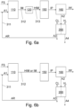
- the feedstock FS and the first aqueous fraction A1 may be supplied to the reactor 150 through other components, such as a mixer 110 and a heater 120, as will be detailed later in connection with Figs. 6a to 6c .
- the first aqueous fraction A1 may comprise make-up fraction A0 and a recyclable aqueous fraction AR receivable from an electrochemical purifier 200.
- the make-up fraction A0 and the recyclable aqueous fraction AR may be mixed with each other upstream from the reactor 150, as in Fig. 1 , or they may be supplied to the reactor 150 separately. If the electrochemical purifier 200 produces sufficiently recyclable aqueous fraction AR, the make-up fraction A0 is not needed.
- the method comprises holding the feedstock FS and the first aqueous fraction A1 in the reactor 150 in a pressure and at a temperature for a period to hydrothermally treat the feedstock FS. As the feedstock FS is treated, the carbon-containing material thereof is converted, and an intermediate product IP is formed in the reactor 150.
- the pressure in the reactor 150 during the treatment is in the in the range 50 bar to 400 bar.
- a temperature in the reactor 150 during the treatment is in the range 250 °C to 500 °C.
- the period should be sufficiently long to facilitate the conversion reactions. However, the period should not be too long to avoid repolymerization and other secondary reactions of the reaction products. Moreover, a long period (i.e. long retention time) implies larger equipment and higher thermal losses, thereby increasing investment and operational costs.
- the temperature and pressure affect the limit, how long the period should be at least. As an example, when the pressure is 150 bar to 250 bar and the temperature is 300 °C to 380 °C, a duration of the period may be e.g. 3 to 10 minutes.
- a duration of the period of time may be e.g. 60 minutes.
- the pressure needs not be constant during the treatment.
- the temperature needs not be constant during the treatment.
- hydrothermal treatment of the carbon-containing material is known by various names including hydrothermal upgrading (HTU), hydrothermal liquefaction (HTL), hydrothermal carbonization (HTC), super critical water liquefaction (SCWL), and super critical water oxidation (SCWO).
- HTU hydrothermal upgrading
- HTL hydrothermal liquefaction
- HTC hydrothermal carbonization
- SCWL super critical water liquefaction
- SCWO super critical water oxidation
- the temperature of the hydrothermally treated carbon-containing material is reduced to 25 - 200 °C and the pressure is reduced to 1 - 70 bar.
- the reduction of temperature and pressure may be done by reducing the temperature and the pressure in the reactor 150 (see Fig. 7 ).
- the reduction of temperature and pressure may be done by reducing the temperature and the pressure in a separator 160 (see Fig. 1 ).
- the intermediate product IP forms in the reactor 150.
- the intermediate product IP is the reaction product of the feedstock FS and the first aqueous fraction A1.
- the method comprises, after the conversion of the carbon-containing material, separating from the intermediate product IP a product fraction PF and a second aqueous fraction A2.
- an embodiment comprises separating from the intermediate product IP a product fraction PF and a second aqueous fraction A2 in a separator 160.
- the separation may be carried out in the reactor 150, as shown in Fig. 7 .
- the separator 160 may be integrated with other parts of the reactor 150.
- the separation of the product fraction PF and the second aqueous fraction A2 is improved by feeding at least part of a third aqueous fraction A3 to the separator 160, which may be an integral part of the reactor 150, or to a location that is between the reactor 150 and the separator 160. Reference is made to Figs. 3 and 4 . It is also noted that the separation of the product fraction PF and the second aqueous fraction A2 can be improved as discussed, even if no aqueous fraction is recycled to the reactor 150 or upstream therefrom (not shown in figures). The separation is improved particularly when hydrocarbons are formed in the hydrothermal conversion process, whereby the intermediate product IP comprises a first phase comprising mainly non-polar compounds and a second phase comprising mainly polar compounds.
- the separation may be carried out after lowering the temperature and pressure to the range discussed above.
- the separation may occur in the reactor 150 as a result of lowering the temperature and pressure of the reactor 150.
- the intermediate product IP may be conveyed from the (high pressure and temperature) reactor 150 to a separator 160 having a lower temperature and pressure within the limits disclosed above.
- hydrocarbons are formed. Hydrocarbons in general are non-polar compounds. In contrast, water is a polar compound. Polar compounds do not dissolve in a non-polar compound.
- a first phase comprising mainly non-polar compounds and a second phase comprising mainly polar compounds may be separated.
- the first phase may constitute the product fraction PF.
- the second phase may constitute the second aqueous fraction A2.
- polar compounds have a different density than the non-polar compounds. Therefore, the phases can be separated, e.g. by means of gravity and/or by using a centrifuge. However, which one of the phases has a higher density may depend on the case at hand. For example, a content of salts affects a density of the second aqueous phase A2, and the type of carbon-containing material may affect the type of hydrocarbons that are produced by the conversion, which affect the density of the product fraction PF.
- the separation of the product fraction PF and the second aqueous fraction A2 from the intermediate product IP comprises allowing phase-separation of polar compounds from non-polar compounds to form a non-polar phase and a polar phase, and the product fraction PF comprises the non-polar phase and the second aqueous fraction A2 comprises the polar phase.
- the second aqueous fraction A2 comprises water.
- a water content of the second aqueous fraction A2 is higher than a water content of the product fraction PF.
- a content of hydrocarbons in the product fraction PF is higher than a content of hydrocarbons in the second aqueous fraction A2.
- the term content refers here to a relative content, as measured in mass percentage (kg/kg).
- the second aqueous fraction A2 comprises water, salt, and organic compounds.
- salt refers to a chemical compound consisting of an ionic assembly of positively charged cations and negatively charged anions, which results in a compound with no net electric charge.
- the product fraction PF comprises oily compounds that are non-polar.
- the product fraction PF has a higher content of oily compounds than the second aqueous fraction A2.
- the product fraction PF has a lower content of water than the second aqueous fraction A2.
- the feedstock FS comprises also salts, in particular salts comprising chloride.
- the second aqueous fraction A2 typically comprises chloride (Cl - ) resulting from the salts of the feedstock FS, which poses problems for recycling the second aqueous fraction A2 as such.
- the method comprises conveying the second aqueous fraction A2 to an electrochemical purifier 200.
- a purpose of the electrochemical purifier 200 is to reduce the amount chloride ions in the aqueous fraction such that a part of the second aqueous fraction A2 can be recycled with less risk of corrosion.
- chloride content can be reduced by removing chloride ions from the recycled part of the second aqueous fraction A2 with the electrochemical purifier 200.
- chlorine gas Cl 2 is produced in the process.
- the second aqueous fraction A2 oftentimes comprises some carbon-containing material, e.g. hydrocarbons.
- some of the carbon-containing materials of the second aqueous fraction A2 are oxidized at the anode 212 and carbon dioxide (CO 2 ) is produced in a first cell 210 of the electrochemical purifier 200.
- Selecting the material of the anode 212 may promote this oxidation.
- the oxidation which is an exothermic reaction, has the benefit that it has been found to decrease the amount of electricity needed for electrochemical purification.
- the electrochemical purifier 200 comprises a first cell 210, an anode 212 arranged in the first cell 210, a second cell 220, and a cathode 222 arranged in the second cell 220.
- anode and cathode both these are electrodes, i.e. capable of conducting electricity.
- the anode 212 is positive relative to the cathode 222.
- the method comprises applying a first voltage V1 to the anode 212 and a second voltage V2 to the cathode 222 such that the first voltage V1 is greater than the second voltage V2 (V1>V2).
- the second aqueous fraction A2 becomes purified by electrolysis.
- the electrolyte in the cells 210, 220 is formed of the second aqueous fraction A2 and/or obtained from another cell of the purifier 200.
- the composition of the electrolyte in the first cell 210 is different from the composition of the electrolyte in the second cell 220.
- a first part of the second aqueous fraction A2 is conveyed to the first cell 210 and a second part of the second aqueous fraction A2 is conveyed to the second cell 220.
- the electrochemical purifier 200 operates by electrodialysis. Therefore, the electrochemical purifier 200 comprises a first ion-exchange membrane 211 arranged between the first cell 210 and the second cell 220.
- the term "cell” refers to a volume of the electrochemical purifier 200, the volume being delimited by walls of the electrochemical purifier 200 and at least one ion-exchange membrane.
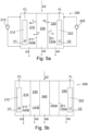
- a cell (210, 220, 230, 240) may be delimited by two ion-exchange membranes, in particular an anion-exchange membrane AEM and a cation exchange membrane CEM, and walls of the purifier 200, as shown in Figs. 5a and 5b . Accordingly, one, two, or more than two, ion-exchange membrane(s) divide the interior of the electrochemical purifier 200 to (at least) two cells: a first cell 210 and a second cell 220.
- an ion-exchange membrane 211 is a semi-permeable membrane that transports certain dissolved ions, while blocking other ions or neutral molecules. Ion-exchange membranes are therefore electrically conductive.
- at least one ion-exchange membrane is used mainly for desalination of the second aqueous fraction A2, moving ions from one cell (e.g. from 210; or 220) to another cell (e.g. to (220 or 230); or e.g. to (210 or 230)) with little or no transfer of water between the cells.
- the first ion-exchange membrane 211 is an anion-exchange membrane or a cation-exchange membrane.
- an anion-exchange membrane is a membrane though which anions (i.e. negative ions) can pass, and conversely, cations (positive ions) cannot pass.
- a cation-exchange membrane is a membrane though which cations (positive ions) can pass, and conversely, anions (i.e. negative ions) cannot pass.
- This operation principle is shown in Fig. 5a for chloride Cl - as an example of an anion, and sodium ion Na + as an example of a cation.
- the anion (Cl - ) can pass the anion-exchange membrane AEM but not the cation exchange membrane CEM.
- the cation (Na + ) can pass the cation-exchange membrane CEM but not the anion exchange membrane AEM.
- the first ion-exchange 211 membrane is an anion-exchange membrane to allow the chloride ion to pass the membrane 211 towards the anode 212 (see Fig. 5a ).
- chloride can be removed from both the cells 210 and 230 (in Fig. 5a ) or, if an anion-exchange membrane is used as the first ion exchange membrane 211 in the embodiment of Fig. 1 , chloride can be removed from both the cells 210 and 220.
- chloride is removed from the first cell 210.
- the chloride ions Cl - are dragged by electronic attractive forces to the anode 212.
- the chloride ions form hypochlorous acid (HClO) and/or become oxidized to form chlorine gas (Cl 2 ).
- a preferable embodiment comprises producing chlorine Cl 2 in the first cell 210.
- the chlorine is produced in the gaseous form.
- An embodiment comprises collecting the chlorine gas.
- the chlorine is not fed back to the process. However, it may be used in another process. It has been found that a low pH in the first cell 210 promotes the production of chlorine as opposed to production of hypochlorous acid (HClO).
- the hydronium ions H + and/or hydroxonium ions H 3 O + are dragged by electronic attractive forces to the cathode 222.
- a hydronium ion H + of a hydroxonium ion H 3 O + reacts at the cathode 222 with another hydronium ion H + or another hydroxonium to form hydrogen gas H 2 and water H 2 O within the second cell 220.
- the method comprises producing hydrogen H 2 in the second cell 220.
- the hydrogen H 2 is produced in gaseous form. Possibilities for utilizing hydrogen H 2 will be discussed below.
- the oxidation of hydrocarbons at the anode 212 may promote the production of hydrogen H 2 , thereby reducing the consumption of electricity.
- the first ion exchange membrane 211 provides for a much smaller use of electricity as compared to electrochemical purification without any ion exchange membrane. Moreover, as the first ion exchange membrane 211 only allow for ions (anions or cation) to pass, the first ion exchange membrane 211 provides for good control of the ion contents of the various aqueous fractions (A3, A4, A5) and in this way, in particular allows for controlling the content of a recyclable aqueous fraction AR, as defined below. Moreover, the first ion exchange membrane 211 helps to keep the pH of the third aqueous fraction A3 low if chlorine gas (Cl 2 ) is to be produced.
- the second aqueous fraction A2 is being purified by electrodialysis in the electrochemical purifier 200.
- a third aqueous fraction A3 is produced into the first cell 210 and a fourth aqueous fraction A4 is produced into the second cell 220.
- the third aqueous fraction A3 is arranged in the first cell 210 and the fourth aqueous fraction A4 is arranged in the second cell 220.
- a fifth aqueous fraction A5 may be produced in a third cell 230.
- Other aqueous fractions are producible in other cells, if used.
- an embodiment comprises mixing the third aqueous fraction A3 and/or mixing the fourth aqueous fraction A4.
- Mixing the third aqueous fraction A3 may be performed by a mixer arranged in the first cell 210 (not shown).
- Mixing the fourth aqueous fraction A4 may be performed by a mixer arranged in the second cell 220.
- the mixing of the third aqueous fraction A3 comprises recycling a part of the third aqueous fraction A3 to the first cell 210.
- a first pump 215 is used for recycling a part of the third aqueous fraction A3 to the first cell 210.
- the mixing of the fourth aqueous fraction A4 comprises recycling a part of the fourth aqueous fraction A4 to the second cell 220.
- a second pump 225 is used for recycling a part of the fourth aqueous fraction A4 to the second cell 220.
- such an amount of the chlorine (Cl 2 ) is produced that a chloride content of the third aqueous fraction A3 is less than a chloride content of the second aqueous fraction A2.
- the third aqueous fraction A3 has an at least 50 % lower content of chloride Cl - than the second aqueous fraction A2.
- the third aqueous fraction A3 has an at least 75 % lower content of chloride Cl - than the second aqueous fraction A2.
- the content is defined in unit of mass per volume (e.g. milligrams per litre).
- a part of the third aqueous fraction A3 can be utilized in the separation of the product fraction and the second aqueous fraction from the intermediate product, as discussed above.
- the third aqueous fraction A3 has a low chloride content, it can be recycled back to the process, i.e. back to the reactor 150.
- the third aqueous fraction A3 has a low content of chloride also in such a case, where the first ion exchange membrane 211 is a cation exchange membrane and the pH of the third aqueous fraction A3 is so low that chlorine is produced at the anode 212. Moreover, in such a case, the third aqueous fraction A3 has lower content of alkali than the second aqueous fraction A2. The low pH also promotes the separation of the polar and non-polar phases of the intermediate product.
- the fifth aqueous fraction A5 (if produced) has a low content of chloride.
- the fifth aqueous fraction A5 can be recycled back to the process, i.e. back to the reactor 150.
- the chloride content of the fifth aqueous fraction A5 is reduced irrespective of whether the chloride ions in the first cell 210 form hypochlorous acid or are oxidized to form chloride.
- the fifth aqueous fraction A5 also has a low content of content of cations, because the cation exchange membrane 221 allows cations to pass.
- a low content of cations implies a low content of alkali ions, in particular sodium and potassium.
- the third aqueous fraction A3 can be supplied to the second cell 220 of the electrochemical purifier, whereby also the fourth aqueous fraction A4 may have a low chloride content.
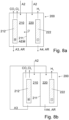
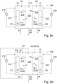
- Fig. 8d shows a further possibility for oxidizing hydrocarbons at the anode 212 and producing a fifth aqueous fraction A5 having a low content of both chloride and sodium.
- the fifth aqueous fraction A5 in Figs. 5a , 8c, and 8d have a reduced content of chloride even if chlorine Cl 2 is not produced at the anode 212.
- the method comprises recycling at least a part of a recyclable aqueous fraction AR from the electrochemical purifier 200 to the reactor 150.
- the recyclable aqueous fraction AR has a lower content of chloride Cl - than the second aqueous fraction A2. This is due to the formation of chlorine Cl 2 and/or hypochlorous acid HClO at the anode 212.
- the recyclable aqueous fraction AR has an at least 50 % lower content of chloride Cl - than the second aqueous fraction A2.
- the recyclable aqueous fraction AR has an at least 75 % lower content of chloride Cl - than the second aqueous fraction A2.
- the content is defined in unit of mass per volume (e.g. milligrams per litre).
- the recyclable aqueous fraction AR comprises the third aqueous fraction A3.
- the recyclable aqueous fraction AR comprises the third aqueous fraction A3 and the fourth aqueous fraction A4.
- the recyclable aqueous fraction AR comprises the fifth aqueous fraction A5.
- the recyclable aqueous fraction AR comprises the fourth aqueous fraction A4.
- the recyclable aqueous fraction AR has been purified from chloride at least to some extent, it can be recycled back to the process, particularly back to the reactor 150.
- the recyclable aqueous fraction AR has a lower content of alkali ions (Na + , K + , Mg 2+ , Ca 2+ ) than the second aqueous fraction A2. This is due to the cathode attracting the alkali ions and the recyclable aqueous fraction AR being taken from another location (e.g. from the first cell 210 as the third aqueous fraction A3 and/or from the third cell 230 as the fifth aqueous fraction A5).
- the recyclable aqueous fraction A5 has an at least 50 % lower content of alkali ions than the second aqueous fraction A2.
- the content is defined in unit of mass per volume (e.g. milligrams per litre).
- an embodiment of the method comprises feeding at least a part of the second aqueous fraction A2 to the first cell 210 and producing carbon dioxide CO 2 in the first cell 210 by oxidizing a carbon-containing compound of the second aqueous fraction A2 at the anode 212.
- Feeding at least a part of the second aqueous fraction A2 to the first cell 210 is schematically shown at least in Figs. 1 , 3 , 7 (in which a part of A2 or A3 may be fed to the second cell 220), 8a, 8b, and 8d. It is noted that also in the embodiment of Fig.
- the second aqueous fraction A2 is first fed to the third cell 230 and desalinated therein to form a fifth aqueous fraction A5, which comprises the hydrocarbons and water of the second aqueous fraction A2. Thereafter, the fifth aqueous fraction A5, which is a part of the second aqueous fraction, is fed to the first cell 210 for oxidating the carbon-containing material therein. As shown in Fig. 8c , a part of the fifth aqueous fraction A5 is fed to the second cell 220, too.
- the second (A2) or the third (A3) aqueous fraction could be fed to the second cell 220 for use as an electrolyte therein.
- any one of the second, third, or fifth aqueous fractions (A2, A3, A5) may be fed to the second cell for use as an electrolyte therein.
- chlorine is produced in the first cell 210, whereby also the third aqueous fraction A3 can be used as at least a part of the recyclable aqueous fraction AR.
- the third aqueous fraction A3 can be used as at least a part of the recyclable aqueous fraction AR.
- a cation-exchange membrane CEM would be used instead of an AEM, then the content of chloride in the second cell 220 would not be significantly reduced. In that case, however, the production of chlorine in the first cell 210 will reduce content of chloride and enable recycling of the third aqueous fraction A3.
- the third aqueous fraction A3 may be recycled e.g. through the second cell 220.
- the amount of produced chlorine depends on pH, as will be detailed below, and also on a magnitude of the electric current running from the anode 212 to the cathode.
- the anode 212 conducts electricity much better than the electrolyte. Therefore, the current is spread over a surface of the anode. Therefore, a density of electric current is an important quantity for characterizing the reduction process at the anode 212.
- the density of the electric current is calculated by dividing the electric current running from the anode 212 to the cathode 222 by an area of the surface of the anode 212.
- the surface herein refers to the interface between the anode 212 and the electrolyte in which the anode 212 is arranged in use. It has been found that a suitable density of the electric current in view of chlorine production, at least when the pH of the aqueous fraction in the first cell 220 is at most 3, is 1 A/m 2 to 50 A/m 2 (Amperes per square metre).
- the current (and thus the current density) can be controlled by controlling a difference of the first voltage V1 and the second voltage V2, the difference V2 subtracted from V1.
- V2 may be set to a ground potential (i.e. zero by definition), whereby only V1 needs to be controlled.
- a direct current (DC) potential may be used for the voltages V1, V2, however, the DC voltage difference V1-V2 may be also controlled.
- an embodiment comprises applying the first voltage V1 to the anode 212 and the second voltage V2 to the cathode 222 such that a density of the electric current running from the anode 212 to the cathode 222 is 1 to 50 Amperes per square metre.
- Figure 1 shows schematically a device for hydrothermally treating feedstock FS that comprises carbon-containing material.
- the device comprises the reactor 150.
- the reactor is configured to hold the feedstock FS and the first aqueous fraction A1 in the reactor 150 in a pressure and at a temperature for a period to hydrothermally treat the feedstock FS for forming the intermediate product IP.
- the temperature and pressure may be within the limits disclosed in the context of the method above. This poses some limitations for the material selections of the reactor 150.
- the device is configured to separate from the intermediate product IP a product fraction PF and a second aqueous fraction A2.
- the device comprises a separator 160 configured to separate from the intermediate product IP a product fraction PF and a second aqueous fraction A2. What has been said about the contents of these fraction in connection with the method applies.
- the device comprises the electrochemical purifier 200 as discussed above.
- the electrochemical purifier 200 is configured to receive the second aqueous fraction A2.
- the electrochemical purifier 200 comprises an electric source 250 (see Fig. 1 ).
- the electric source 250 is configured to generate the first voltage V1 and the second voltage V2 as discussed above.
- the electrochemical purifier 200 comprises a first electric conductor 214 configured to conduct the first voltage V1 to the anode 212.
- the electrochemical purifier 200 comprises a second electric conductor 224 configured to conduct the second voltage V2 to the cathode 222.
- the device comprises a first pipeline 310 configured to recycle at least a part of a recyclable aqueous fraction A5 from the electrochemical purifier 200 to the reactor 150 optionally through other components of the device.
- the first pipeline 310 is configured to recycle at least a part of a third aqueous fraction A3 from the first cell 210 to the reactor 150 directly.
- Figs. 6a to 6c more typical embodiments are shown in Figs. 6a to 6c .
- Figs. 6b and 6c comprise a mixer 110.
- a first part 311 of the first pipeline 310 is configured to recycle at least a part of the recyclable aqueous fraction A5 from the electrochemical purifier 200 to the mixer 110.
- a second part 312 of the first pipeline 310 is configured to convey input material IM or heated input material HIM from the mixer 110 to the reactor 150, which in Fig. 6c comprises a heater 120.
- the mixer 110 may comprise a heater, in which case heated input material HIM can be conveyed from the mixer 110 to the reactor 150 through the second part 312 of the first pipeline 310.
- the reactor 150 comprises a heater 120 or the device comprises a separate heater 120
- input material IM can be conveyed from the mixer 110 to the reactor 150 (or to the heater 120) through the second part 312.
- a heater 120 that is not comprised by the reactor 150
- the second part 312 of the first pipeline 310 is configured to convey input material IM or heated input material HIM from the mixer 110 to the reactor 150 optionally through other components of the device; e.g. in Fig. 6a through the heater 120 and in Figs. 6b and 6c directly to the reactor 150.
- the embodiment of Fig. 6a comprises the mixer 110 and a heater 120.
- the second part 312 of the first pipeline 310 is configured to convey at least a part of an input material IM from the mixer 110 to the heater 120.
- a third part 313 of the first pipeline 310 is configured to convey heated input material HIM from the heater 120 to the reactor 150.
- the mixer 110, the heater 120, or the reactor 150 (or a combination of these) is configured to mix the feedstock FS with the first aqueous fraction A1 and heat the mixture thereof to the process temperature disclosed above.
- the pressure may increase because of the increasing temperature (reference is made to saturation point of water).
- the device may comprise a pump or pumps to pump both the feedstock FS and the first aqueous fraction A1 to the reactor 150 separately or in the form of their mixture.
- the anode 212 drags the chloride ions (Cl - ) towards the anode 212.
- the cathode 222 drags the alkali metal ions and earth alkali metal ions (Na + , K + , Mg 2+ , Ca 2+ ) and hydronium ions (H + ) towards the cathode 222.
- the chemical reactions in the cells 210, 220 include reactions at the anode 212, formally as: 2H 2 O ⁇ O 2 + 4H + + 4e- .
- an anion-exchange membrane may prevent the hydronium H + from escaping the first cell 210, whereby the presence of hydronium may decrease the pH therein.
- the chemical reactions in the cells include reactions at the cathode 222, formally as: 2H 2 O + 2e- ⁇ 2H 2 + 2OH - ; and 2H + + 2e - ⁇ H 2 , the electrons being emitted by the cathode 222.
- the chloride ions may form metal radicals, which, when reacting with each other, form the chlorine gas.
- the reactions include 2M + 2Cl - ⁇ 2(MCl • ) + 2e - ⁇ 2M + Cl 2 + 2e - , the electrons e- being absorbed by the anode 212.
- the metal material M used on the surface of the anode 212 plays a significant role in the formation of chlorine gas.
- the anode 212 comprises at least one of ruthenium (Ru), iridium (Ir), platinum (Pt), tin (Sn), lead (Pb), boron (B), iron (Fe), nickel (Ni), and graphite.
- Steel is an example of material comprising iron (Fe).
- some of these metals may be present in the form of a suitable compound.
- anode 212 comprises at least one of ruthenium oxide (RuO 2 ), iridium oxide (IrO 2 ), platinum (Pt), tin oxide (SnO 2 ), lead oxide (PbO 2 ), boron doped diamond (BDD), iron (Fe), steel, nickel (Ni), and graphite.
- the metal is preferably present on the surface of the anode 212.
- the anode 212 comprises on its surface at least one ruthenium (Ru), iridium (Ir), platinum (Pt), tin (Sn), lead (Pb), boron (B), iron (Fe), nickel (Ni), and graphite.
- the anode 212 comprises on its surface at least one of ruthenium oxide (RuO 2 ), iridium oxide (IrO 2 ), platinum (Pt), tin oxide (SnO 2 ), lead oxide (PbO 2 ), boron doped diamond (BDD), iron (Fe), steel, nickel (Ni), and graphite.
- a core of the anode may be made of a first metal, e.g. titanium, fully or partly coated with a second material, the second material being selected from the group of RuO 2 , IrO 2 , Pt, SnO 2 , PbO 2 , BDD, Fe, steel, Ni, and graphite.
- the material of the cathode 222 is not so critical.
- the cathode comprises electrically conductive material.
- an electrically conductive material means material whose resistivity is at most 10 -2 ⁇ m at a temperature of 20°C. Examples include stainless steel, acid-proof steel, titanium, graphite, and conductive polymers.
- the cathode comprises steel, such as stainless steel or acid-proof steel.
- the shape of the electrodes may be formed as a plate, as a mesh, as a rod, or as a series of rods.
- a shape of an electrode may be planar or substantially planar.
- co-axial electrodes the inner electrode being rod-like, and the outer electrode being circumferential and laterally surrounding the inner electrode (not shown, but reference is made to US2015/0122741 ).
- the chlorine Cl 2 that is formed at the anode does not necessarily escape from the first cell 210 in the form of gas. Instead (or in addition) at least some of the chlorine may react with water to form hypochlorous acid (HClO), and the hypochlorous acid (HClO) may form hypochlorite ions (ClO - ) according to the following reactions: Cl 2 + H 2 O ⁇ Cl - + HClO + H + HClO ⁇ ClO - + H +
- the distribution of these two chlorine species depends on the pH of the solution.
- the pH in the first cell 210 should be kept low to avoid the formation of hypochlorous acid (HClO) and hypochlorite ions (ClO - ).
- the low pH thus has the benefit that a content of hypochlorous acid (HClO) and hypochlorite ions (ClO - ), both which are toxic, is reduced.
- an embodiment of the method comprises purifying the second aqueous fraction A2 in the electrochemical purifier 200 such that a pH of the third aqueous A3 fraction is at most 3. It has been found that the tendency of forming hypochlorous acid (HClO) and hypochlorite ions (ClO - ) is significantly reduced below this limit.
- the method comprises purifying the second aqueous fraction A2 such that a pH of the third aqueous A3 fraction is at most 2.
- the pH in the first cell 210 may decrease because of the electrochemical purification as such, which involves oxidation organic compounds present in the second aqueous fraction A2. In brief, decomposition of organic compounds will produce H + and CO 2 which both cause acidity in the first cell 210.
- water of the second aqueous fraction A2 form metals radical compounds at the anode 212, formally as: M + H 2 O ⁇ M(HO • ) + H + + e -
- the hydronium H + decreases the pH in the first cell 210, and with reference to Fig. 5a , the first ion-exchange membrane 211 may prevent hydronium H + from passing to the second cell 220. In this way, the pH in the first cell 210 tends to decrease naturally. For this reason, too, the selection for the metal material of the anode should be considered carefully.
- the materials disclosed above for the anode suitably promote the oxidation of organic compounds, too, in addition to formation of chlorine.
- the pH of the electrolyte in the first cell 210 can be measured, and, provided that the natural decrement of pH is not sufficient for production of chlorine gas, suitable acid may be added.
- the acid may be added for keeping the pH below 3, more preferably below 2.
- hydrochloric acid (HCl) may be used for the purpose, if needed.
- the pH may be measured from the first cell 210, or if a circulation is used for mixing (see Fig. 5a ), from the circulation comprising the first pump 215.
- the first ion-exchange membrane 211 is an anion-exchange membrane AEM. This prevents the hydronium from escaping the first cell 210 and in this way helps to keep the pH low for the formation of chlorine gas.
- the first ion-exchange membrane 211 is an anion-exchange membrane AEM and the electrochemical purifier 200 comprises a second ion-exchange membrane 221 that is a cation-exchange membrane CEM.
- the electrochemical purifier 200 may comprise a set of ion-exchange membranes, the set of ion-exchange membranes comprising the first ion-exchange membrane 211, which is an anion-exchange membrane AEM, and the second ion-exchange membrane 221, which is a cation-exchange membrane CEM.
- the ion-exchange membranes are arranged such that the first ion-exchange membrane 211 is that one of the ion-exchange membranes that is closest to the anode 212. In other words, a cation-exchange membrane is not arranged between the first ion-exchange membrane 211 (which is AEM) and the anode 212. Moreover, preferably, the ion-exchange membranes are arranged such that the second ion-exchange membrane 221 is that one of the ion-exchange membranes that is closest to the cathode. In other words, an anion-exchange membrane is not arranged between the second ion-exchange membrane 221 (which is CEM) and the cathode 222. Reference is made to Figs. 5a and 5b .
- a third cell 230 remains between the anion-exchange membrane AEM and the cation-exchange membrane CEM.
- a fifth aqueous fraction A5 is receivable from the third cell 230.
- the chloride ions from the third cell 230 can also transfer through the first ion-exchange membrane 211 to the cathode 212 to form the chlorine as detailed above. Therefore, the fifth aqueous fraction A5 can be used in a similar way as the third aqueous fraction A3.
- the recyclable aqueous fraction AR may comprise at least a part of the fifth aqueous fraction A5.
- the throughput of desalinated water of the electrochemical purifier 200 may be improved by using further ion-exchange membranes.
- the further ion-exchange membranes (further relative to the embodiment of Fig. 5a ) may be used such that each anion-exchange membrane AEM of the further ion-exchange membranes is arranged between two cation-exchange membranes CEM (see Fig. 5b ).
- each cation-exchange membrane CEM of the further ion-exchange membranes may be arranged between two anion-exchange membranes AEM (see Fig. 5b ).
- two AEMs can be arranged next to each other and/or two CEMs can be arranged next to each other, because then they function in a similar manner as a single AEM or CEM, respectively. However, since they function as one, there is no technical reason for doing so.
- the electrochemical purifier 200 comprises an even number (2N) of ion-exchange membranes 211, wherein the even number is two times an integer N that is at least one.
- the type of the ion-exchange membranes 211 is selected such that N pieces of the ion-exchange membranes (i.e. half of them) are anion-exchange membranes AEM and N pieces of the ion-exchange membranes (i.e. the other half of them) are cation-exchange membranes CEM.
- the even number (2N) is two, four six, eight, or more than eight.
- the electrochemical purifier 200 may comprise an odd number (2N+1) of ion-exchange membranes, such as three, five, seven, or more. As readable from the above, only one ion-exchange membrane may suffice. In such a case, it is preferably an anion-exchange membrane.
- a sixth aqueous fraction A6 is receivable from a fourth cell 240.
- the chloride ions of the fourth cell cannot pass the CEM that is arranged between the fourth cell 240 and the anode 212.
- the sixth aqueous fraction A6 comprises chloride.
- the sixth aqueous fraction A6 may be fed to a point upstream from the electrochemical purifier and downstream from the reactor 150 or downstream from the separator 160, if the separation is made in a separator 160.
- the sixth aqueous fraction A6 may thus e.g.
- the sixth aqueous fraction A6 may be fed to the electrochemical purifier 200, e.g. such that at least a part of the sixth aqueous fraction A6 is fed to the first cell 210.
- the feedstock FS As for the efficiency of the hydrothermal treatment of the carbon-containing material comprised by the feedstock FS, it has been found that many elements from the group I or II of the periodic table of elements, in particular sodium (Na), potassium (K), magnesium (Mg) and calcium (Ca), act as catalysts for the hydrothermal treatment reactions in the reactor 150. These materials may be added to the process, if needed. However, most often the feedstock FS comprises a sufficient amount of these compounds naturally in the form of salts. Of these materials, the elements from the group I of the periodic table of elements seem to be preferable catalysts.
- the feedstock FS comprises salt or salts comprising at least one of sodium (Na), potassium (K), magnesium (Mg) and calcium (Ca)
- the content of at least one of them in the reactor 150 can be increased by recycling also a part of such a fourth aqueous fraction A4, which is receivable from the second cell 220.
- the cations (the sodium cation Na + shown as an example in Fig. 5 ) are dragged by the cathode 222 to the cathode 222, whereby the concentration of the cations of these elements increase in the second cell 220.
- these elements form hydroxides, such as sodium hydroxide (NaOH), potassium hydroxide (KOH), magnesium hydroxide (Mg(OH) 2 ), and calcium hydroxide (Ca(OH) 2 ).
- hydroxides such as sodium hydroxide (NaOH), potassium hydroxide (KOH), magnesium hydroxide (Mg(OH) 2 ), and calcium hydroxide (Ca(OH) 2 ).
- the method preferably comprises recovering a fourth aqueous fraction A4 from the second cell 220.
- the fourth aqueous fraction A4 comprises at least one sodium hydroxide (NaOH), potassium hydroxide (KOH), magnesium hydroxide (Mg(OH) 2 ), and calcium hydroxide (Ca(OH) 2 ).
- NaOH sodium hydroxide
- KOH potassium hydroxide
- Mg(OH) 2 magnesium hydroxide
- Ca(OH) 2 calcium hydroxide
- Figs. 2 and 4 showing recycling a part of the fourth aqueous fraction A4, whereby the recyclable aqueous fraction AR comprises at least a part of the fourth aqueous fraction A4.
- Recycling least a part of the fourth aqueous fraction A4 to the reactor 150 has the further benefit that the fourth aqueous fraction A4 is, in such a case, can be used also to neutralize the third aqueous fraction A3, when both are comprised by the recyclable aqueous fraction AR.
- a pH of the third aqueous fraction A3 is low to generate the chlorine gas.
- the hydrothermal treatment in the reactor 150 may be performed at a higher pH.
- a pH of the fourth aqueous fraction A4 is high. Therefore, in addition to providing the catalysts to the reactor 150, recycling at least a part of the fourth aqueous fraction A4 to the reactor 150 also increases a pH therein.
- the fourth aqueous fraction A4 does not comprise any one of NaOH, KOH, Mg(OH) 2 , and Ca(OH) 2 .
- the feedstock FS comprises salt or salts comprising at least one of sodium (Na), potassium (K); whereby the fourth aqueous fraction A4 comprises sodium hydroxide (NaOH) and/or potassium hydroxide (KOH).
- the at least part of the fourth aqueous fraction A4 can be conveyed separate from the third aqueous fraction A3 to the reactor 150, the mixer 110, or the heater 120.
- a pH of the aqueous streams may be more easily controllable, and the equipment may remain simpler, if the at least part of the fourth aqueous fraction A4 is recycled to the reactor 150 with the at least part of the third aqueous fraction A3 that is recycled to the reactor 150.
- Figs. 2 and 4 Reference is made to Figs. 2 and 4 .
- the at least part of the fourth aqueous fraction A4 is recycled by mixing it with the at least part of the third aqueous A3 fraction to obtain the recyclable aqueous fraction AR.
- the mixing may occur upstream of the reactor 150, and if used, also upstream of the mixer 110. In this way the pH of the mixture of the aqueous fraction A3 and A4 (denoted by A3+A4 and AR) can be measured and controlled to be suitable for the process.
- such an amount of the fourth aqueous fraction A4 mixed with the at least part of the third aqueous A3 fraction that a pH of the mixture (A3+A4) of the at least part of the fourth aqueous fraction A4 and the at least part of the third aqueous fraction A3 is at least 5. More preferably, the pH of the mixture (A3+A4) is at least 6 or at least 6.5.
- the low pH of the third aqueous fraction A3 can be utilized in the separation of the product fraction PF and the second aqueous fraction A2. This applies particularly when a pH of the third aqueous fraction A3 is at most 3 to promote production of chlorine Cl 2 in the first cell 210.
- the non-polar phase (as discussed above) is insoluble to the polar phase (as discussed above) at least when pH is neutral or low.
- a pH of the intermediate product IP may be, in some cases, relatively high, which may hinder the separation of the product fraction PF and the second aqueous fraction A2 from the intermediate product IP.
- an embodiment comprises utilising at least part of the third aqueous fraction A3 to improve the separation of the product fraction PF and the second aqueous fraction A2 from the intermediate product IP.
- the at least a part of the third aqueous fraction A3 can be supplied to the process to a location downstream from the hydrothermal conversion reaction.
- the at least a part of the third aqueous fraction A3 can be supplied to the separator 160, or upstream therefrom.
- a corresponding device comprises a fourth pipeline 340 for conveying at least a part of the third aqueous fraction A3 to the rector 150, to a separator 160, or to a location that is between the reactor 150 and the separator 160 for utilising at least part of the third aqueous fraction A3 to improve the separation of the product fraction PF and the second aqueous fraction A2 from the intermediate product IP.
- An embodiment comprises recycling a mixture of both (at least a part of) the third aqueous fraction A3 and (at least a part of) the fifth aqueous fraction A5 both to the reactor 150 and the separator 160.
- An embodiment comprises recycling at least a part of (only) the fifth aqueous fraction A5 to the reactor 150 and recycling at least a part of (only) the third aqueous fraction A3, which has a lower pH than the fifth aqueous fraction A5, to separator 160 for improving the separation of the product fraction PF and the second aqueous fraction A2 from the intermediate product IP.
- the product fraction PF may comprise a lot of oxygen, which may pose problems if the product fraction PF stored for a long time because of internal oxidation. Therefore, the product fraction PF may be refined.
- the product fraction PF may be refined for example in a hydrodeoxygenation (HDO) process.
- HDO hydrodeoxygenation
- the hydrogen H 2 produced in the second cell 220 can be used for refining the product fraction PF.
- the product fraction PF and the hydrogen H 2 are conveyed to a refining reactor 170, wherein the product fraction PF and the hydrogen H 2 are allowed to react with each other.
- the refining process in the refining reactor 170 may be e.g. a hydrodeoxygenation (HDO) process.
- HDO hydrodeoxygenation
- suitable catalysts may be used in such a process.
- Suitable catalysts for HDO include nikel-molybdenium (NiMo) and cobalt-molybdenium (CoMo). In HDO a temperature varies typically in the range of 200°C - 350°C and a pressure varies typically in the range of 50 bar - 150 bar.
- an embodiment comprise producing hydrogen H 2 in the second cell 220.
- a preferable embodiment comprises collecting or utilizing the hydrogen produced in the second cell 220.
- An embodiment comprises allowing at least a part of the hydrogen H 2 produced in the second cell 220 to chemically react with the product fraction PF or a part thereof. As a result, a refined fraction RF is obtained.
- the at least a part of the hydrogen H 2 produced in the second cell 220 is allowed to chemically react with the product fraction PF in the presence of a catalyst, such as NiMo or CoMo or Na or K. More preferably the at least a part of the hydrogen H 2 produced in the second cell 220 is allowed to chemically react with the product fraction PF in a pressure that is in the range in the range of 50 bar - 150 bar and at a temperature that is in the range of 200°C - 350°C.
- a catalyst such as one of the catalysts disclosed above, may be present also in these process conditions.
- An embodiment of the device comprises a refining reactor 170, a second pipeline 320 configured to convey at least a part of the product fraction PF to the refining reactor 170, and a third pipeline 330 configured to convey at least part of the of the hydrogen H 2 produced in the second cell 220 to the second pipeline 320 or to the refining reactor 170.
- the hydrogen may be premixed in the second pipeline 320 with the product fraction PF upstream from the refining reactor 170 (not shown).
- the hydrogen H 2 may be conveyed directly to the refining reactor 170 (see Fig. 3 ).
- the refining reactor 170 may be a HDO reactor.
- the refining reactor 170 may be configured to withstand a pressure of at least 150 bar and a temperature of at least 350 °C.
- the refining reactor 170 may contain catalyst configured to catalyse chemical reactions between the product fraction PF and the hydrogen H 2 .
- a temperature and a pressure of the intermediate product fraction IP may be lowered before the separation, or for the separation to occur.
- an embodiment comprises lowering a temperature of the intermediate product IP to the range of 25 - 200 °C and lowering a pressure in which the of the intermediate product IP is held to a range of 1 - 70 bar before or during separating the product fraction PF and the second aqueous fraction A2 from the intermediate product IP.
- At least a part of the third aqueous fraction A3 may be utilised, as detailed above.
- An embodiment comprises separating also carbon dioxide CO 2 from the intermediate product IP. Separation of carbon dioxide is shown in Fig. 4 . However, even if not shown in other figures, separation of carbon dioxide can be applied in those embodiments, too.
- the temperature is high.
- the feedstock FS and the recyclable aqueous fraction AR need to be heated. Heating may be done in the reactor 150.
- to facilitate chemical reactions between the feedstock FS and the recyclable aqueous fraction AR they need to be mixed with each other. The mixing, too, can be done in the reactor 150. Reference is made to Fig. 1 .
- the mixing may be done even if the materials are not hot, i.e. before heating.
- the device for running the method comprises a mixer 110 and the mixing may be performed in the mixer 110.
- both the feedstock FS and the recyclable aqueous fraction AR are fed to the mixer 110, and input material IM or heated input material HIM for the rector is receivable from the mixer 110.
- the material(s) may be heated in the mixer 110, in a separate heater 120, or in the reactor 150.
- the feedstock FS and the recyclable aqueous fraction AR are fed to the mixer 110 to form input material IM for the reactor 150.
- the input material is, prior to feeding into the reactor 150, heated in a heater 120.
- the heater 120 Upon heating the input material IM, the heater 120 lets out heated input material HIM, which is conveyed to the reactor 150.
- Fig 6b shows two embodiments in the same figure.
- the feedstock FS and the recyclable aqueous fraction AR are fed to the mixer 110 wherein they are mixed, but not heated, to form input material IM for the reactor 150.
- the (non-heated) input material IM is fed to the reactor 150, wherein it is heated to facilitate the chemical reactions between the feedstock and the first aqueous fraction A1 comprising the recyclable aqueous fraction AR.
- the feedstock FS and the recyclable aqueous fraction AR are fed to the mixer 110, wherein they are mixed and heated to form heated input material HIM for the reactor 150.
- the heated input material HIM is fed to the reactor 150, wherein the chemical reactions between the feedstock and the first aqueous fraction A1 comprising the recyclable aqueous fraction AR are facilitated, because the heated input material is sufficiently hot.
- the material(s) may be heated in one, two, or all of: the mixer 110, the heater 120, and the reactor 150.
- the feedstock FS and the recyclable aqueous fraction AR are supplied to the reactor 150 by feeding the feedstock FS and the recyclable aqueous fraction AR to the mixer 110 and mixing the feedstock FS with the recyclable aqueous fraction AR in the mixer 110 to form an input material IM.
- the recyclable aqueous fraction AR may be supplied in the form of the first aqueous fraction A1, which comprises the recyclable aqueous fraction AR and may further comprise the make-up fraction A0 (see Fig. 1 ).
- the make-up fraction A0 may comprise of water or consist of water (fresh water or sea water).
- the input material IM may be fed to the rector 150 without heating, as discussed above.
- an embodiment comprises feeding the input material IM to the reactor 150.
- the input material IM may be heated (in the mixer 110 or in a heater 120) to form the heated input material HIM, whereby an embodiment comprises feeding the heated the input material HIM to the reactor 150.
- the input material is heated in a heater 120, which is separate from the reactor 150.
- a heater 120 comprises heating the input material IM in a heater 120 to form heated input material HIM and feeding the thus heated input material HIM to the reactor 150.
- a heater 120 may be part of the reactor 150.
- the input material IM may be fed to the heater 120 of the reactor 150 to form heated input material HIM, and the heated input material HIM may be conveyed, within the reactor 150 to a reaction zone 152 of the reactor 150.
- Fig. 6c shows a reactor 150 having an integrated heater 120 and a reaction zone 152.
- the invention also relates to a use of an electrochemical purifier 200 as detailed above.
- the electrochemical purifier 200 is used for purifying an aqueous fraction, i.e. the second aqueous fraction A2 discussed above, which results from hydrothermal treatment of carbon-containing material.
- the electrochemical purifier 200 is used also for reducing content of chloride of the aqueous fraction to enable recycling of at least a part of the aqueous fraction to the hydrothermal treatment of the carbon-containing material.
- the electrochemical purifier 200 is used such that chlorine gas and/or hypochlorous acid is produced at the anode 212 of the electrochemical purifier 200.
Landscapes
- Chemical & Material Sciences (AREA)
- Engineering & Computer Science (AREA)
- Chemical Kinetics & Catalysis (AREA)
- Organic Chemistry (AREA)
- Oil, Petroleum & Natural Gas (AREA)
- Electrochemistry (AREA)
- General Chemical & Material Sciences (AREA)
- Metallurgy (AREA)
- Materials Engineering (AREA)
- Life Sciences & Earth Sciences (AREA)
- Inorganic Chemistry (AREA)
- Environmental & Geological Engineering (AREA)
- Wood Science & Technology (AREA)
- Hydrology & Water Resources (AREA)
- Water Supply & Treatment (AREA)
- Thermal Sciences (AREA)
- Physics & Mathematics (AREA)
- Automation & Control Theory (AREA)
- Health & Medical Sciences (AREA)
- Analytical Chemistry (AREA)
- Molecular Biology (AREA)
- Water Treatment By Electricity Or Magnetism (AREA)
Applications Claiming Priority (1)
| Application Number | Priority Date | Filing Date | Title |
|---|---|---|---|
| FI20235698 | 2023-06-21 |
Publications (1)
| Publication Number | Publication Date |
|---|---|
| EP4480925A1 true EP4480925A1 (de) | 2024-12-25 |
Family
ID=91465407
Family Applications (1)
| Application Number | Title | Priority Date | Filing Date |
|---|---|---|---|
| EP24180675.1A Pending EP4480925A1 (de) | 2023-06-21 | 2024-06-07 | Verfahren und vorrichtung zur hydrothermalen behandlung von kohlenstoffhaltigem material |
Country Status (1)
| Country | Link |
|---|---|
| EP (1) | EP4480925A1 (de) |
Citations (3)
| Publication number | Priority date | Publication date | Assignee | Title |
|---|---|---|---|---|
| JPH11267698A (ja) * | 1998-03-26 | 1999-10-05 | Ube Ind Ltd | 廃棄物の処理方法およびその装置 |
| US6348143B1 (en) * | 1997-08-11 | 2002-02-19 | Ebara Corporation | Hydrothermal electrolysis method and apparatus |
| US20150122741A1 (en) | 2012-01-30 | 2015-05-07 | Originoil, Inc. | Systems and methods for treating wastewater |
-
2024
- 2024-06-07 EP EP24180675.1A patent/EP4480925A1/de active Pending
Patent Citations (3)
| Publication number | Priority date | Publication date | Assignee | Title |
|---|---|---|---|---|
| US6348143B1 (en) * | 1997-08-11 | 2002-02-19 | Ebara Corporation | Hydrothermal electrolysis method and apparatus |
| JPH11267698A (ja) * | 1998-03-26 | 1999-10-05 | Ube Ind Ltd | 廃棄物の処理方法およびその装置 |
| US20150122741A1 (en) | 2012-01-30 | 2015-05-07 | Originoil, Inc. | Systems and methods for treating wastewater |
Similar Documents
| Publication | Publication Date | Title |
|---|---|---|
| Garcia-Rodriguez et al. | Electrochemical treatment of highly concentrated wastewater: A review of experimental and modeling approaches from lab-to full-scale | |
| Tang et al. | Municipal wastewater treatment plants coupled with electrochemical, biological and bio-electrochemical technologies: Opportunities and challenge toward energy self-sufficiency | |
| Hou et al. | Nickel-based membrane electrodes enable high-rate electrochemical ammonia recovery | |
| Shamaei et al. | Treatment of oil sands produced water using combined electrocoagulation and chemical coagulation techniques | |
| Pikaar et al. | Electrochemical abatement of hydrogen sulfide from waste streams | |
| Iskander et al. | Resource recovery from landfill leachate using bioelectrochemical systems: opportunities, challenges, and perspectives | |
| Rocha et al. | Application of electrochemical oxidation as alternative treatment of produced water generated by Brazilian petrochemical industry | |
| CN106687417B (zh) | 使用由废水生产的氧化剂的工业废水处理方法及装置 | |
| Ntagia et al. | Electrochemical treatment of industrial sulfidic spent caustic streams for sulfide removal and caustic recovery | |
| Sakar et al. | Ammonium removal and recovery from real digestate wastewater by a modified operational method of membrane capacitive deionization unit | |
| AU2009304585A1 (en) | Treatment of solutions or wastewater | |
| Zhao et al. | Technoeconomic assessment of electrochemical hydrogen peroxide production with gas diffusion electrodes under scenarios relevant to practical water treatment | |
| Johnson et al. | Electrochemical oxidation of distillery wastewater by dimensionally stable Ti-RuO2 anodes | |
| Fajardo et al. | Treatment of a synthetic phenolic mixture by electrocoagulation using Al, Cu, Fe, Pb, and Zn as anode materials | |
| CN105585180A (zh) | 一种高效反渗透浓水处理方法 | |
| Alvarez-Pugliese et al. | Perspectives on electrochemical valorization of organic waste | |
| Lourinho et al. | Electrolytic treatment of swine wastewater: recent progress and challenges | |
| KR101828913B1 (ko) | 전기충전 인프라 구축용 염분차 발전 시스템 | |
| Liu et al. | Electrochemical catalytic oxidation treatment of highly saline organic wastewater in coal chemical industry | |
| Snyder et al. | Perspective on the electrochemical recovery of phosphate from wastewater streams | |
| Meena et al. | Sustainable approaches for tannery wastewater treatment using a hybrid electrocoagulation-electrooxidation process | |
| Das et al. | Green hydrogen from wastewater─ a dual crisis resolution | |
| CN117920736A (zh) | 一种飞灰处理及固废无害资源化利用的装置系统及方法 | |
| Shankar et al. | Simultaneous treatment and energy production from PIW using electro coagulation & microbial fuel cell | |
| Uğurlu et al. | Experimental Investigation of Chemical Oxygen Demand, Lignin and Phenol Removal from Paper Mill Effluents Using Three-Phase Three-Dimensional Electrode Reactor. |
Legal Events
| Date | Code | Title | Description |
|---|---|---|---|
| PUAI | Public reference made under article 153(3) epc to a published international application that has entered the european phase |
Free format text: ORIGINAL CODE: 0009012 |
|
| STAA | Information on the status of an ep patent application or granted ep patent |
Free format text: STATUS: THE APPLICATION HAS BEEN PUBLISHED |
|
| AK | Designated contracting states |
Kind code of ref document: A1 Designated state(s): AL AT BE BG CH CY CZ DE DK EE ES FI FR GB GR HR HU IE IS IT LI LT LU LV MC ME MK MT NL NO PL PT RO RS SE SI SK SM TR |
|
| STAA | Information on the status of an ep patent application or granted ep patent |
Free format text: STATUS: REQUEST FOR EXAMINATION WAS MADE |
|
| 17P | Request for examination filed |
Effective date: 20250220 |