EP4480803A1 - Method for producing a gravity-based structure (gbs) at a specialized production site - Google Patents
Method for producing a gravity-based structure (gbs) at a specialized production site Download PDFInfo
- Publication number
- EP4480803A1 EP4480803A1 EP22927498.0A EP22927498A EP4480803A1 EP 4480803 A1 EP4480803 A1 EP 4480803A1 EP 22927498 A EP22927498 A EP 22927498A EP 4480803 A1 EP4480803 A1 EP 4480803A1
- Authority
- EP
- European Patent Office
- Prior art keywords
- concreted
- slab
- gbs
- central part
- outer walls
- Prior art date
- Legal status (The legal status is an assumption and is not a legal conclusion. Google has not performed a legal analysis and makes no representation as to the accuracy of the status listed.)
- Pending
Links
Images



Classifications
-
- B—PERFORMING OPERATIONS; TRANSPORTING
- B63—SHIPS OR OTHER WATERBORNE VESSELS; RELATED EQUIPMENT
- B63B—SHIPS OR OTHER WATERBORNE VESSELS; EQUIPMENT FOR SHIPPING
- B63B35/00—Vessels or similar floating structures specially adapted for specific purposes and not otherwise provided for
- B63B35/44—Floating buildings, stores, drilling platforms, or workshops, e.g. carrying water-oil separating devices
-
- E—FIXED CONSTRUCTIONS
- E02—HYDRAULIC ENGINEERING; FOUNDATIONS; SOIL SHIFTING
- E02B—HYDRAULIC ENGINEERING
- E02B17/00—Artificial islands mounted on piles or like supports, e.g. platforms on raisable legs or offshore constructions; Construction methods therefor
- E02B17/02—Artificial islands mounted on piles or like supports, e.g. platforms on raisable legs or offshore constructions; Construction methods therefor placed by lowering the supporting construction to the bottom, e.g. with subsequent fixing thereto
- E02B17/025—Reinforced concrete structures
-
- B—PERFORMING OPERATIONS; TRANSPORTING
- B63—SHIPS OR OTHER WATERBORNE VESSELS; RELATED EQUIPMENT
- B63B—SHIPS OR OTHER WATERBORNE VESSELS; EQUIPMENT FOR SHIPPING
- B63B21/00—Tying-up; Shifting, towing, or pushing equipment; Anchoring
- B63B21/24—Anchors
- B63B21/26—Anchors securing to bed
- B63B21/29—Anchors securing to bed by weight, e.g. flukeless weight anchors
-
- B—PERFORMING OPERATIONS; TRANSPORTING
- B63—SHIPS OR OTHER WATERBORNE VESSELS; RELATED EQUIPMENT
- B63B—SHIPS OR OTHER WATERBORNE VESSELS; EQUIPMENT FOR SHIPPING
- B63B25/00—Load-accommodating arrangements, e.g. stowing, trimming; Vessels characterised thereby
- B63B25/02—Load-accommodating arrangements, e.g. stowing, trimming; Vessels characterised thereby for bulk goods
- B63B25/08—Load-accommodating arrangements, e.g. stowing, trimming; Vessels characterised thereby for bulk goods fluid
- B63B25/12—Load-accommodating arrangements, e.g. stowing, trimming; Vessels characterised thereby for bulk goods fluid closed
-
- B—PERFORMING OPERATIONS; TRANSPORTING
- B63—SHIPS OR OTHER WATERBORNE VESSELS; RELATED EQUIPMENT
- B63B—SHIPS OR OTHER WATERBORNE VESSELS; EQUIPMENT FOR SHIPPING
- B63B5/00—Hulls characterised by their construction of non-metallic material
- B63B5/14—Hulls characterised by their construction of non-metallic material made predominantly of concrete, e.g. reinforced
-
- B—PERFORMING OPERATIONS; TRANSPORTING
- B63—SHIPS OR OTHER WATERBORNE VESSELS; RELATED EQUIPMENT
- B63B—SHIPS OR OTHER WATERBORNE VESSELS; EQUIPMENT FOR SHIPPING
- B63B5/00—Hulls characterised by their construction of non-metallic material
- B63B5/14—Hulls characterised by their construction of non-metallic material made predominantly of concrete, e.g. reinforced
- B63B5/16—Hulls characterised by their construction of non-metallic material made predominantly of concrete, e.g. reinforced monolithic
-
- B—PERFORMING OPERATIONS; TRANSPORTING
- B63—SHIPS OR OTHER WATERBORNE VESSELS; RELATED EQUIPMENT
- B63B—SHIPS OR OTHER WATERBORNE VESSELS; EQUIPMENT FOR SHIPPING
- B63B73/00—Building or assembling vessels or marine structures, e.g. hulls or offshore platforms
-
- E—FIXED CONSTRUCTIONS
- E02—HYDRAULIC ENGINEERING; FOUNDATIONS; SOIL SHIFTING
- E02B—HYDRAULIC ENGINEERING
- E02B17/00—Artificial islands mounted on piles or like supports, e.g. platforms on raisable legs or offshore constructions; Construction methods therefor
- E02B17/02—Artificial islands mounted on piles or like supports, e.g. platforms on raisable legs or offshore constructions; Construction methods therefor placed by lowering the supporting construction to the bottom, e.g. with subsequent fixing thereto
-
- E—FIXED CONSTRUCTIONS
- E02—HYDRAULIC ENGINEERING; FOUNDATIONS; SOIL SHIFTING
- E02D—FOUNDATIONS; EXCAVATIONS; EMBANKMENTS; UNDERGROUND OR UNDERWATER STRUCTURES
- E02D27/00—Foundations as substructures
- E02D27/32—Foundations for special purposes
- E02D27/52—Submerged foundations, i.e. submerged in open water
-
- B—PERFORMING OPERATIONS; TRANSPORTING
- B63—SHIPS OR OTHER WATERBORNE VESSELS; RELATED EQUIPMENT
- B63B—SHIPS OR OTHER WATERBORNE VESSELS; EQUIPMENT FOR SHIPPING
- B63B2207/00—Buoyancy or ballast means
- B63B2207/02—Variable ballast or buoyancy
-
- B—PERFORMING OPERATIONS; TRANSPORTING
- B63—SHIPS OR OTHER WATERBORNE VESSELS; RELATED EQUIPMENT
- B63B—SHIPS OR OTHER WATERBORNE VESSELS; EQUIPMENT FOR SHIPPING
- B63B2231/00—Material used for some parts or elements, or for particular purposes
- B63B2231/60—Concretes
- B63B2231/64—Reinforced or armoured concretes
-
- E—FIXED CONSTRUCTIONS
- E02—HYDRAULIC ENGINEERING; FOUNDATIONS; SOIL SHIFTING
- E02B—HYDRAULIC ENGINEERING
- E02B17/00—Artificial islands mounted on piles or like supports, e.g. platforms on raisable legs or offshore constructions; Construction methods therefor
- E02B2017/0056—Platforms with supporting legs
- E02B2017/0069—Gravity structures
-
- E—FIXED CONSTRUCTIONS
- E02—HYDRAULIC ENGINEERING; FOUNDATIONS; SOIL SHIFTING
- E02D—FOUNDATIONS; EXCAVATIONS; EMBANKMENTS; UNDERGROUND OR UNDERWATER STRUCTURES
- E02D2250/00—Production methods
- E02D2250/0023—Cast, i.e. in situ or in a mold or other formwork
-
- E—FIXED CONSTRUCTIONS
- E02—HYDRAULIC ENGINEERING; FOUNDATIONS; SOIL SHIFTING
- E02D—FOUNDATIONS; EXCAVATIONS; EMBANKMENTS; UNDERGROUND OR UNDERWATER STRUCTURES
- E02D2250/00—Production methods
- E02D2250/0046—Production methods using prestressing techniques
-
- E—FIXED CONSTRUCTIONS
- E02—HYDRAULIC ENGINEERING; FOUNDATIONS; SOIL SHIFTING
- E02D—FOUNDATIONS; EXCAVATIONS; EMBANKMENTS; UNDERGROUND OR UNDERWATER STRUCTURES
- E02D2300/00—Materials
- E02D2300/0004—Synthetics
- E02D2300/0018—Cement used as binder
- E02D2300/002—Concrete
-
- E—FIXED CONSTRUCTIONS
- E02—HYDRAULIC ENGINEERING; FOUNDATIONS; SOIL SHIFTING
- E02D—FOUNDATIONS; EXCAVATIONS; EMBANKMENTS; UNDERGROUND OR UNDERWATER STRUCTURES
- E02D2300/00—Materials
- E02D2300/0026—Metals
- E02D2300/0029—Steel; Iron
Definitions
- the invention pertains to fabrication (construction) of gravity-based structures (GBS) and can be used as part of development of various kinds of near-shore and offshore production (including natural gas liquefaction, ammonia, methanol, hydrogen production, and power generation), transportation, transshipment, and storage facilities.
- GRS gravity-based structures
- a gravity-based structure (GBS, a fixed gravity-based offshore platform) is a platform, which is fixed on a seabed with the help of its own weight. Gravity-based structures are used in coastal and shelf waters where the water depths are sufficient to support a superstructure of the required height above the water level once the GBS is installed on the seabed.
- a GBS can feature internal compartments to enable its floatability during transportation to its installation site. GBS are designed to be floatable and have ballasting systems to enable long-distance transportation and installation for operation at the intended offshore site without using expensive lifting and transportation equipment. GBS are mostly made of reinforced concrete and steel.
- GBS are produced at production sites and shipyards that have special equipment.
- GBS gravity-based structure
- a method which is the closest to the proposed one, features a gravity-based structure (GBS) fabrication for Adriatic LNG, an offshore liquified natural gas receiving and regasification terminal built at Algeciras' production site in Spain ( Design and Construction on Gravity Based Structure and Modularized LNG Tanks for the Adriatic LNG Terminal. Lisa B. Waters et al. ExxonMobil Development Company. 2007. http://www.ivt.ntnu.no/ept/fag/tep4215/innhold/LNG%20Conferences/2007/f scommand/PS6_7_Waters_s.pdf . )
- This GBS is made in a form of a rectangular prism with a top slab, a base slab, an intermediate support slab for self-supported LNG tanks, external walls, internal longitudinal and transversal walls to separate the compartments.
- the above production method features the following:
- This method has the following drawbacks.
- the rectangular prism-shaped GBS has large draft when transported to the installation site, which makes transportation through shallow water areas impossible.
- the rectangular prism-shaped GBS is not protected from external influences such as ice drift and emergency ship impact.
- the technical problem resolved with the invention is as follows. Taking into account the increasing share of production and infrastructure facilities located in underdeveloped areas, including coastal and water area of Arctic seas, there is an urgent need to develop a new and efficient method for construction of gravity-based structures which could house production, transportation, transshipment and storage complexes for various purposes in the coastal and water areas and adapted for use in water areas with ice conditions.
- a method for producing a GBS representing a three-dimensional reinforced concrete structure with internal walls separating compartments and aimed for installation on a bottom of a water object and which may serve as a foundation to accommodate a topside for various purposes.
- the GBS may stay floating during its transportation though water routes from a production location to an installation location, and when installed on a seabed, it can resist ice loads from an iced basin.
- the topside can be erected either immediately after the GBS production or after the GBS placement onto a seabed or at one of the interim locations during the GBS transportation from the production location to the installation location.
- a reinforcement cage is assembled, a formwork is installed, embedments are set and supports for equipment are concreted on the top slab.
- a reinforcement cage is assembled, a formwork is installed and an intermediate slab is concreted, post-tensioned, and inside at least one compartment shaped by the walls, intermediate slab and top slab, a tank for storage of liquid is assembled from panels, delivered through the wall openings.
- the technical result is acheived by the GBS fabricated with the protruding part and it means the following.
- the protruding part adds to buoyancy of the GBS and the entire structure, as well as reduces its submersion during transportation to the installation site. Additional ballast compartments in the peripheral part of the GBS inside the protruding part make it easy to balance the GBS, i.e. to settle the GBS down evenly, without trim and list.
- Increased width of the GBS lower part adds to stability of the entire structure during its transportation, enabling to install the topside structure of greater height and weight onto the GBS.
- the GBS that uses the protruding part instead of having the same volume across its height has a tangible advantage in terms of the draft and the overall weight-to-floatability ratio, which enables a much greater displacement for a relatively modest increase in the platform's own weight.
- the protruding part of the GBS also protects the central part, which can accommodate main storage compartments, from drifting ice and emergency ship impact.
- the production program implies mass production of GBSs as part of a staged process at a specialized fabrication site with dry docks.
- the location of the fabrication site facilities allows producing materials for every separate stage of fabrication within limits of a separate facility with subsequent transportation to dry docks for use in the GBS fabrication.
- the GBS fabrication sequence is designed to optimize the use of equipment and personnel and reduce construction time through parallel performance of part of the work stages.
- the GBS is fabricated as follows.
- the dry dock is isolated from the adjacent water area using a dock gate, then the dock is drained with pumps. Then, at the bottom of the dock, an area with a cover of compacted crushed rock is prepared for fabrication of the GBS foundation slab.
- Reinforcement is cut and bent and reinforcement cages are fabricated and labelled in a reinforcement shop. Reinforcement elements are transported to the dry dock by road and fed at the GBS reinforcement cage assembly site with loaders or lifting cranes. The GBS reinforcement cage is assembled by welding, lashing, and sleeving.
- duct tubes for bundles of post-tensioning reinforcement strands are installed in the tensioned structures, as well as the anchors and embedments for equipment to be installed.
- Traditional formwork panels are produced from cut wood and laminated plywood in the formwork shop.
- the traditional formwork is used to concrete objects of smaller height, mainly for slabs and supports.
- Basic elements of the inventory formwork are panels or blocks, frames, bearing structures, connectors and fastenings.
- panel-type formwork Two types of inventory formwork are applied: panel-type formwork and slipforming.
- Panel-type formwork is collapsible and consists of large-sized elements, accelerating construction of large-scale objects.
- Slipforming consists of two identical rows of panels, 1.0 - 1.2 m high, rigidly connected to one another by bolts and attached to a special frame, which is moved upwards by jacks along with the structure's concreting process.
- Slipforming is used for the GBS walls concreting. With slipforming applied, concreting is monolithic, that is, without the "cold seams", thus improving the structure's performance parameters.
- the use of slipforming enables the GBS walls to be concreted very fast - over 2.5 meters upwards per day.
- Permanent formwork is used when formwork removal is impossible, e.g. during concreting of the intermediate ceiling slab when the equipment is installed inside the compartment.
- This type of formwork is also used for construction of pit structures in LNG tanks and other parts of the GBS, removal of which is labor-intensive after closure of outer structures.
- Concrete which is the main construction material for GBS production, is mixed at a concrete batching plant, located close to the dry docks. Location of the concrete batching plant ensures the least distance for concrete to be transported to the pouring point.
- Bulk materials for concrete mixing may be delivered to the fabrication site via a quay, located in front of the concrete batching plant, and it secures the shortest way for the materials from the offloading point to the place where they are stored and consequently used.
- the GBS production employs special concrete mix designs of high strength, having the pre-requisite density and durability features.
- the use of concrete of different densities in combination with weight control allows to achieve optimal targets for mass, buoyancy and stability of the structure.
- the concrete mix is delivered to the dry dock by truck mixers.
- the concrete is poured into the formwork with concrete pumps.
- the GBS is fabricated with an intermediate slab 7 to accommodate at least one liquid storage tank 8 ( Fig. 4 ), as concreting of individual sections of the walls 2 of the central part between the base slab 1 and intermediate slab 7 is completed, concreting of the GBS intermediate slab 7 begins, in parallel with concreting of the internal and external walls 3 and 4 in the GBS central part.
- a reinforcement cage is assembled, formwork is erected and the intermediate slab 7 is concreted.
- the central part of the slab is bent upwards before concreting to ensure camber in the opposite direction.
- the slab settles down due to its weight and takes design configuration enabling partial offset of downward bending.
- the liquid storage tank 8 is locally erected from panels delivered through the openings in the walls.
- top slabs 6 of the GBS protruding part are connected to the external walls 4 of the central part by extending and tying protruding reinforcements into sleeves and anchor rods that were earlier flush-mounted during slipforming of walls 4 in accordance with the design.
- supports are built from reinforced concrete along the outer edge of the GBS protruding part above the top slab 6 for the purpose of installation of berthing structures and fenders for berthing and mooring of vessels enabling the use of GBS structures as a berth. These supports are erected with the help of an inventory formwork.
- a reinforcement cage is assembled, formwork is installed, embedments are set in and the supports 10 are concreted to provide support for load-bearing structures of the topside cages which may house process equipment ( Fig. 5 ).
- the post-tensioning materials workshop accommodates storage of reinforcement strands, duct tubes and anchores, preparation of materials and equipment to perform post-tensioning.
- the equipment is installed in the dry dock. Once the equipment is ready, the post-tensioning materials are transported to the dry dock where strand bundles are installed and tensioned to the design values with anchoring and transmission of tensioning force to anchoring devices on reinforced concrete structures of the GBS.
- Concrete structures are post-tensioned using "tension on concrete” with bonding restoration, which means that after the concrete of the tensioned reinforced concrete structures of the GBS is poured, the strands are forced/pulled through the pre-installed duct tubes made of corrugated steel. After the concrete has reached the minimum required strength, the strand bundles are tensioned and fixed thus transmitting the tensioning force to steel anchoring devices pre-installed onto the short ends of the structure body. Reinforcement strands are tensioned with hydraulic jacks. After strand bundles are tensioned and pull-out testing is done, the duct tubes are filled with nonshrink cement mortar and all temporary openings and niches are filled up. The duct tubes will protect the reinforcement strands from external impact and partially transfer load from the strands to the concrete along the entire length of the structure.
- the targeted performance can be achieved more efficiently, especially for limit states group II, such as crack resistance and impermeability. As a result, it reduces the amount of non-tensioned reinforcement required and contributes to reducing the structure weight, as well as increases the overall spatial stiffness of the load-bearing reinforced concrete cage of the GBS.
- topside modules 12 may be fabricated in parallel and independently of the GBS construction schedule, and then installed on the supports 10 with the help of a specialized jacking and skidding system.
- the supports 10 are also the main load-carrying elements supporting the bearing guardrails of the topsides skidding system.
- cranes are also used in the dry docks, allowing to install heavy equipment and steel structures onto the GBS from the area near the dock.
- the dry dock 13 with the GBS inside is gradually filled with water 14 from the nearby water area with the help of pumps.
- GBS compartments are checked for leak tightness by hydraulic and pneumatic tests.
- GBS ballast compartments are flooded as well, to increase the structure's weight and thus ensure its steadiness on the dock bottom.
- GBS is fixed inside the dock with mooring hawsers and retention and guiding dolphins located at the bottom of the dry dock. Once GBS testing and mooring is complete, water is pumped out of the compartments of the moored GBS to ensure its floating up during the high tide.
- the GBS is towed out of the dock by tugboats. After being towed out of the dry dock, the GBS is towed to the installation site. By the onshore winches and by tugs, the GBS is installed in the point of destination at a quayside, where the GBS is connected to onshore communication lines in the deposit area. Once its position is confirmed as correct, the GBS is ballasted to be installed onto a foundation, previously arranged in the bottom of a water body.
Landscapes
- Engineering & Computer Science (AREA)
- Mechanical Engineering (AREA)
- General Engineering & Computer Science (AREA)
- Structural Engineering (AREA)
- Civil Engineering (AREA)
- Ocean & Marine Engineering (AREA)
- Chemical & Material Sciences (AREA)
- Combustion & Propulsion (AREA)
- Paleontology (AREA)
- Mining & Mineral Resources (AREA)
- General Life Sciences & Earth Sciences (AREA)
- Life Sciences & Earth Sciences (AREA)
- Architecture (AREA)
- On-Site Construction Work That Accompanies The Preparation And Application Of Concrete (AREA)
- Filling Or Discharging Of Gas Storage Vessels (AREA)
- Foundations (AREA)
- Manufacturing Of Tubular Articles Or Embedded Moulded Articles (AREA)
Abstract
Description
- The invention pertains to fabrication (construction) of gravity-based structures (GBS) and can be used as part of development of various kinds of near-shore and offshore production (including natural gas liquefaction, ammonia, methanol, hydrogen production, and power generation), transportation, transshipment, and storage facilities.
- A gravity-based structure (GBS, a fixed gravity-based offshore platform) is a platform, which is fixed on a seabed with the help of its own weight. Gravity-based structures are used in coastal and shelf waters where the water depths are sufficient to support a superstructure of the required height above the water level once the GBS is installed on the seabed. A GBS can feature internal compartments to enable its floatability during transportation to its installation site. GBS are designed to be floatable and have ballasting systems to enable long-distance transportation and installation for operation at the intended offshore site without using expensive lifting and transportation equipment. GBS are mostly made of reinforced concrete and steel.
- GBS are produced at production sites and shipyards that have special equipment.
- There exists a method for fabricating a gravity-based structure (GBS) made from reinforced concrete to support a floating power plant and store liquefied natural gas which has a form of a rectangular prism with a base slab, a top slab, and side walls. The method consists in placing reinforcement bars, concreting the GBS elements, and performing pre-stressing and post-tensioning of the GBS elements (
KR20150136823A - A method, which is the closest to the proposed one, features a gravity-based structure (GBS) fabrication for Adriatic LNG, an offshore liquified natural gas receiving and regasification terminal built at Algeciras' production site in Spain (Design and Construction on Gravity Based Structure and Modularized LNG Tanks for the Adriatic LNG Terminal. Lisa B. Waters et al. ExxonMobil Development Company. 2007. http://www.ivt.ntnu.no/ept/fag/tep4215/innhold/LNG%20Conferences/2007/f scommand/PS6_7_Waters_s.pdf. )
- This GBS is made in a form of a rectangular prism with a top slab, a base slab, an intermediate support slab for self-supported LNG tanks, external walls, internal longitudinal and transversal walls to separate the compartments.
- The above production method features the following:
- a GBS construction site is prepared, including installation of concrete cavities for steel skirts and installation of these steel skirts, in this case the skirts hang loose in the concrete cavities in such a way that the GBS weight is shifted to the site backfilled with gravel and to the concrete foundations;
- a rectangular reinforcement cage is assembled for the base slab, formwork for the base slab is installed and the base slab is then concreted;
- once concreting of individual base slab areas is completed, reinforcement cages for the external and internal walls are assembled and the external and internal walls are slip-formed except the short-end walls on one of the GBS sides (on the side where the LNG tanks were installed);
- simultaneously with walls concreting, a reinforcement cage for the intermediate slab is assembled, formwork is erected and the intermediate slab is concreted;
- roof beams are fabricated and installed;
- as separate wall sections are concreted, a reinforcement cage for the top slab is assembled, the top slab formwork is installed and then the top slab is concreted,
- insulation and a second barrier for LNG tank compartments are installed;
- sections for self-supporting LNG tanks are erected;
- the short-end walls on one of the GBS sides are concreted (on the side where the LNG tanks are installed);
- the top slab and base slab, as well as inner and outer walls are post-tensioned with the rereinforcement strands.
- This method has the following drawbacks.
- Installation of concrete cavities for steel skirts and steel skirts increases the scope and duration of works at a preparatory stage, presence of concrete cavities makes preparation of the foundation more complicated.
- Use of roof beams complicates construction works and requires use of cranes with higher carrying capacity.
- Concreting of the short-end walls on one side of the GBS (on which the LNG tanks are installed) is carried out the last after the tanks are installed in the GBS compartments, which increases the construction time and violates monolithic nature of the reinforced concrete structure due presence of "cold joints" in this section.
- The rectangular prism-shaped GBS has large draft when transported to the installation site, which makes transportation through shallow water areas impossible.
- The rectangular prism-shaped GBS is not protected from external influences such as ice drift and emergency ship impact.
- The technical problem resolved with the invention is as follows. Taking into account the increasing share of production and infrastructure facilities located in underdeveloped areas, including coastal and water area of Arctic seas, there is an urgent need to develop a new and efficient method for construction of gravity-based structures which could house production, transportation, transshipment and storage complexes for various purposes in the coastal and water areas and adapted for use in water areas with ice conditions.
- To resolve the above-said problem, there was proposed a method for producing a GBS representing a three-dimensional reinforced concrete structure with internal walls separating compartments and aimed for installation on a bottom of a water object and which may serve as a foundation to accommodate a topside for various purposes. Besides, the GBS may stay floating during its transportation though water routes from a production location to an installation location, and when installed on a seabed, it can resist ice loads from an iced basin. The topside can be erected either immediately after the GBS production or after the GBS placement onto a seabed or at one of the interim locations during the GBS transportation from the production location to the installation location.
- The technical issue is solved by a method of a gravity-based structure (GBS) production, meaning that
- a reinforcement cage is assembled for a rectangular base slab, a base slab formwork is installed and the base slab is then concreted,
- as separate sections of the base slab are concreted, reinforcement cages for inner and outer walls are assembled and concreted with slipforming,
- as separate wall sections are concreted, a reinforcement cage for top slab is assembled, a top slab formwork is installed and then the top slab is concreted,
- the top slab and base slab, as well as inner and outer walls are post-tensioned with reinforcement strands,
- along with that, as per the invention,
- the GBS is fabricated, including a central part and a protruding part that have the common base slab,
- inner and outer walls as well as the top slab are concreted for the central part of GBS, that takes form of a rectangular prism,
- as separate sections of the outer walls of the central part are concreted, a reinforcement cage is assembled, a formwork is installed and concreting is performed for inner and outer walls of the GBS protruding part, the outer walls of which are made along a perimeter of the base slab, and at the same time height of the outer walls of the protruding part is lower than height of the outer walls of the central part,
- as separate wall sections of the protruding part are concreted, a reinforcement cage is assembled and a formwork is installed for the top slab of the protruding part and then concreted,
- and the base and top slabs of the central part, as well as the inner and outer walls of the central part and protruding part are post-tensioned as the top slabs of the central part and protruding part are concreted and the concrete of the post-tensioned structures gains required strength.
- In addition, it is advisable to concrete the top slab with upward bending of its central part so that the central part of the top slab lowers later on its own weight to a design position.
- Moreover, in the preferred option of the invention, as separate sections of the top slab of the central part are concreted, a reinforcement cage is assembled, a formwork is installed, embedments are set and supports for equipment are concreted on the top slab.
- Furthermore, as the outer and inner walls of the central part are concreted, it is advisable to leave openings for formwork removal and further installation of equipment inside the GBS compartments shaped by the walls and slabs.
- Should it be required to accommodate at least one tank for storage of liquid in the GBS, then simultaneously with concreting of the walls of the central part, a reinforcement cage is assembled, a formwork is installed and an intermediate slab is concreted, post-tensioned, and inside at least one compartment shaped by the walls, intermediate slab and top slab, a tank for storage of liquid is assembled from panels, delivered through the wall openings.
- The technical result is acheived by the GBS fabricated with the protruding part and it means the following. The protruding part adds to buoyancy of the GBS and the entire structure, as well as reduces its submersion during transportation to the installation site. Additional ballast compartments in the peripheral part of the GBS inside the protruding part make it easy to balance the GBS, i.e. to settle the GBS down evenly, without trim and list. Increased width of the GBS lower part adds to stability of the entire structure during its transportation, enabling to install the topside structure of greater height and weight onto the GBS.
- Unlike platforms that are installed and towed in deepwater areas, the GBS that uses the protruding part instead of having the same volume across its height has a tangible advantage in terms of the draft and the overall weight-to-floatability ratio, which enables a much greater displacement for a relatively modest increase in the platform's own weight.
- The protruding part of the GBS also protects the central part, which can accommodate main storage compartments, from drifting ice and emergency ship impact.
- Erecting both side walls and short-end walls before the top slab is formed as well as having possibility to assemble the tanks from separate panels in a confined compartment helps to accelerate the GBS fabrication and to reduce the number of "cold welds" in the reinforced concrete construction.
- To reduce the overall GBS production time, certain stages are carried out in parallel.
-
-
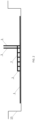
Fig. 1 shows fabrication of the base slab and walls of the GBS central part between the base slab and the intermediate slab. -
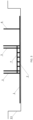
Fig. 2 - fabrication of the base slab and intermediate slab as well as inner walls of the GBS central part. -
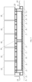
Fig. 3 - fabrication of the inner and outer walls of the GBS central part. -
Fig. 4 - fabrication of the outer walls of the GBS central part, top slab, topside supports on the top slab, outer walls of the GBS protruding part and tanks for liquids storage inside the GBS. -
Fig. 5 - fabrication of the top slab of the GBS central part, top slab of the GBS protruding part and top structure supports. -
Fig. 6 - the fabricated GBS when towed out of a dock, front view. -
Figure 7 - the fabricated GBS when towed out of the dock, side view. - The production program implies mass production of GBSs as part of a staged process at a specialized fabrication site with dry docks. The location of the fabrication site facilities allows producing materials for every separate stage of fabrication within limits of a separate facility with subsequent transportation to dry docks for use in the GBS fabrication. The GBS fabrication sequence is designed to optimize the use of equipment and personnel and reduce construction time through parallel performance of part of the work stages.
- The GBS is fabricated as follows.
- The dry dock is isolated from the adjacent water area using a dock gate, then the dock is drained with pumps. Then, at the bottom of the dock, an area with a cover of compacted crushed rock is prepared for fabrication of the GBS foundation slab.
- Reinforcement is cut and bent and reinforcement cages are fabricated and labelled in a reinforcement shop. Reinforcement elements are transported to the dry dock by road and fed at the GBS reinforcement cage assembly site with loaders or lifting cranes. The GBS reinforcement cage is assembled by welding, lashing, and sleeving.
- Simultaneously with the reinforcement cage, duct tubes for bundles of post-tensioning reinforcement strands are installed in the tensioned structures, as well as the anchors and embedments for equipment to be installed.
- Three types of formworks are used for the GBS concreting: traditional formwork, inventory formwork and permanent formwork. In a formwork shop, traditional and permanent formwork is produced, and inventory formwork assembly sections are assembled. Completed sections are stored in a formwork laydown area and, when needed, they are transported to the dry dock and installed for concreting of the GBS structure.
- Traditional formwork panels are produced from cut wood and laminated plywood in the formwork shop. The traditional formwork is used to concrete objects of smaller height, mainly for slabs and supports.
- Basic elements of the inventory formwork are panels or blocks, frames, bearing structures, connectors and fastenings. Depending on the structure to be concreted, two types of inventory formwork are applied: panel-type formwork and slipforming.
- Panel-type formwork is collapsible and consists of large-sized elements, accelerating construction of large-scale objects. Slipforming consists of two identical rows of panels, 1.0 - 1.2 m high, rigidly connected to one another by bolts and attached to a special frame, which is moved upwards by jacks along with the structure's concreting process. Slipforming is used for the GBS walls concreting. With slipforming applied, concreting is monolithic, that is, without the "cold seams", thus improving the structure's performance parameters. Moreover, the use of slipforming enables the GBS walls to be concreted very fast - over 2.5 meters upwards per day.
- Permanent formwork is used when formwork removal is impossible, e.g. during concreting of the intermediate ceiling slab when the equipment is installed inside the compartment. This type of formwork is also used for construction of pit structures in LNG tanks and other parts of the GBS, removal of which is labor-intensive after closure of outer structures.
- Concrete, which is the main construction material for GBS production, is mixed at a concrete batching plant, located close to the dry docks. Location of the concrete batching plant ensures the least distance for concrete to be transported to the pouring point.
- Bulk materials for concrete mixing may be delivered to the fabrication site via a quay, located in front of the concrete batching plant, and it secures the shortest way for the materials from the offloading point to the place where they are stored and consequently used.
- The GBS production employs special concrete mix designs of high strength, having the pre-requisite density and durability features. The use of concrete of different densities in combination with weight control allows to achieve optimal targets for mass, buoyancy and stability of the structure. The concrete mix is delivered to the dry dock by truck mixers. The concrete is poured into the formwork with concrete pumps.
- Concreting starts with sectionalized concrete casting of the
base slab 1, which is common for the GBS central and protruding parts (Fig. 1 ). A reinforcement cage is assembled for therectangular base slab 1, a formwork for thebase slab 1 is installed and thebase slab 1 is then concreted. As individual sections of thebase slab 1 are completed, reinforcement cages are assembled in the central part of the GBS forinternal walls 2 with the help of an inventory formwork. In parallel, reinforcement installation is performed forinternal walls 3 andexternal walls 4 in the GBS central part (Fig. 2 ,3 ), which are slipformed. During this process, the GBS central part is shaped as a rectangular prism. For the purposes of formwork removal and subsequent equipment installation in GBS compartments, relatively small service openings are left in the walls to be further thoroughly closed and sealed once the work inside the compartments is finished. - In case the GBS is fabricated with an
intermediate slab 7 to accommodate at least one liquid storage tank 8 (Fig. 4 ), as concreting of individual sections of thewalls 2 of the central part between thebase slab 1 andintermediate slab 7 is completed, concreting of the GBSintermediate slab 7 begins, in parallel with concreting of the internal andexternal walls intermediate slab 7 is concreted. - As individual sections of the
external walls 4 of the central part are concreted, a reinforcement cage is assembled, formwork is installed, and external and internal walls of the protruding part are concreted section by section, using slipforming. Theexternal walls 5 of the GBS protruding part are erected all along the base slab perimeter, with theexternal walls 5 of the protruding part being lower than theexternal walls 4 of the central part. - In parallel, in the sections where concreting of
walls top slab 9 of the GBS central part begins. For this purpose, a reinforcement cage is assembled for thetop slab 9, formwork is erected for thetop slab 9 and thetop slab 9 is concreted. In addition, to erect the formwork, the scaffolding and trestles are installed inside the GBS compartments allowing to avoid using roof beams. Using scaffolding in combination with the formwork provides their universal usage both for building thetop slab 9 and for performing subsequent preparation and installation of structural elements oftanks 8 at different heights, which ultimately results in overall construction acceleration. - To offset the downward bending of the
top slab 9 due to its weight, the central part of the slab is bent upwards before concreting to ensure camber in the opposite direction. Once the concreting is completed and the formwork is removed, the slab settles down due to its weight and takes design configuration enabling partial offset of downward bending. Using a beamless design for thetop slab 9 with uneven thickness similar to an arc where the slab is thicker near its edges than in the span (not shown in the drawings) enables better target specifications for weight and rigidity as well as accelerated formwork instalation through simplification of the slab bottom surface, which has no protruding parts. - At least in one of the compartments formed by internal reinforced-
concrete walls 3,intermediate slab 7 andtop slab 9, theliquid storage tank 8 is locally erected from panels delivered through the openings in the walls. - In parallel, as the
external walls 5 of the GBS protruding part are completed, concreting oftop slabs 6 of the GBS protruding part begins (Fig. 4 ,5 ). Thetop slabs 6 of the GBS protruding part are connected to theexternal walls 4 of the central part by extending and tying protruding reinforcements into sleeves and anchor rods that were earlier flush-mounted during slipforming ofwalls 4 in accordance with the design. - If the intended use of the GBS includes berthing of vessels, supports are built from reinforced concrete along the outer edge of the GBS protruding part above the
top slab 6 for the purpose of installation of berthing structures and fenders for berthing and mooring of vessels enabling the use of GBS structures as a berth. These supports are erected with the help of an inventory formwork. - Should it be required to fabricate a GBS with
supports 10 for a topside equipment to be installed on thetop slab 9, then a reinforcement cage is assembled, formwork is installed, embedments are set in and thesupports 10 are concreted to provide support for load-bearing structures of the topside cages which may house process equipment (Fig. 5 ). - The post-tensioning materials workshop accommodates storage of reinforcement strands, duct tubes and anchores, preparation of materials and equipment to perform post-tensioning. In the areas where sequence of works makes it possible to start this type of work, the equipment is installed in the dry dock. Once the equipment is ready, the post-tensioning materials are transported to the dry dock where strand bundles are installed and tensioned to the design values with anchoring and transmission of tensioning force to anchoring devices on reinforced concrete structures of the GBS.
- Concrete structures are post-tensioned using "tension on concrete" with bonding restoration, which means that after the concrete of the tensioned reinforced concrete structures of the GBS is poured, the strands are forced/pulled through the pre-installed duct tubes made of corrugated steel. After the concrete has reached the minimum required strength, the strand bundles are tensioned and fixed thus transmitting the tensioning force to steel anchoring devices pre-installed onto the short ends of the structure body. Reinforcement strands are tensioned with hydraulic jacks. After strand bundles are tensioned and pull-out testing is done, the duct tubes are filled with nonshrink cement mortar and all temporary openings and niches are filled up. The duct tubes will protect the reinforcement strands from external impact and partially transfer load from the strands to the concrete along the entire length of the structure.
- With post-tensioning during GBS construction, the targeted performance can be achieved more efficiently, especially for limit states group II, such as crack resistance and impermeability. As a result, it reduces the amount of non-tensioned reinforcement required and contributes to reducing the structure weight, as well as increases the overall spatial stiffness of the load-bearing reinforced concrete cage of the GBS.
- Closing of process openings in the GBS walls, concreting of post-tension anchors, and cleaning of concrete surface take place in the end.
- After the GBS fabrication is complete,
equipment 11 is installed inside compartments and on thetop slab 9 and a modulartopside structure 12 is installed onto thesupports 10 on the top slab 9 (seeFig. 6 and7 ).Topside modules 12 may be fabricated in parallel and independently of the GBS construction schedule, and then installed on thesupports 10 with the help of a specialized jacking and skidding system. The supports 10 are also the main load-carrying elements supporting the bearing guardrails of the topsides skidding system. - Besides the skidding system, cranes are also used in the dry docks, allowing to install heavy equipment and steel structures onto the GBS from the area near the dock.
- After the GBS construction and equipment installation are complete, the
dry dock 13 with the GBS inside is gradually filled withwater 14 from the nearby water area with the help of pumps. At each stage of the dock flooding, GBS compartments are checked for leak tightness by hydraulic and pneumatic tests. Along with the dock flooding, GBS ballast compartments are flooded as well, to increase the structure's weight and thus ensure its steadiness on the dock bottom. - Once tests are complete, GBS is fixed inside the dock with mooring hawsers and retention and guiding dolphins located at the bottom of the dry dock. Once GBS testing and mooring is complete, water is pumped out of the compartments of the moored GBS to ensure its floating up during the high tide.
- The GBS is towed out of the dock by tugboats. After being towed out of the dry dock, the GBS is towed to the installation site. By the onshore winches and by tugs, the GBS is installed in the point of destination at a quayside, where the GBS is connected to onshore communication lines in the deposit area. Once its position is confirmed as correct, the GBS is ballasted to be installed onto a foundation, previously arranged in the bottom of a water body.
Claims (5)
- A method for fabricating a gravity-based structure (GBS), consisting in that a reinforcement cage is assembled for a rectangular base slab, base slab formwork is installed and the base slab is then concreted, as separate sections of the base slab are concreted, reinforcement cages for inner and outer walls are assembled and the inner and outer walls are concreted by slipforming, as separate wall sections are concreted, a reinforcement cage for a top slab is assembled, a top slab formwork is installed and then the top slab is concreted, the top slab and base slab, as well as inner and outer walls are post-tensioned with reinforcement strands, characterized in that the GBS is fabricated including a central part and protruding part that have the common base slab, besides the inner and outer walls as well as the top slab are concreted for the central part of GBS, that takes form of a rectangular prism, as separate sections of the outer walls of the central part are concreted, a reinforcement cage is assembled, formwork is installed and concreting is performed for inner and outer walls of the GBS protruding part, the outer walls of which are made along the perimeter of the base slab, and at the same time the height of the outer walls of the protruding part is lower than the height of the outer walls of the central part, as separate wall sections of the protruding part are concreted, a reinforcement cage is assembled and formwork is installed for a top slab of the protruding part and then concreted, and the base and top slabs of the central part, as well as the inner and outer walls of the central part and protruding part are post-tensioned as the top slabs of the central part and protruding part are concreted and the concrete of the post-tensioned structures is cured.
- The method according to claim 1, where the top slab is concreted with upward bending of its central part so that the central part of the slab lowers on its own weight to a design position.
- The method according to claim 1, where, as soon as separate sections of the top slab of the central part are concreted, a reinforcement cage is assembled, a formwork is installed, embedments are set and supports for equipment are concreted on the top slab.
- The method according to claim 1, where, in the course of the outer and inner walls of the central part being concreted, openings are left for form work removal and further installation of equipment inside the GBS compartments shaped by the walls and slabs.
- The method according to claim 3, where, simultaneously with concreting of the walls of the central part, a reinforcement cage is assembled, aformwork is installed and an intermediate slab is concreted, post-tensioned, and inside at least one compartment shaped by the walls, intermediate slab and top slab, a tank for storage of liquids is arranged with panels, delivered through temporary wall openings.
Applications Claiming Priority (2)
| Application Number | Priority Date | Filing Date | Title |
|---|---|---|---|
| RU2022103801A RU2771197C1 (en) | 2022-02-15 | 2022-02-15 | Method for manufacturing a gravity-type base (gtb) at a specialized production site |
| PCT/RU2022/000312 WO2023158337A1 (en) | 2022-02-15 | 2022-10-14 | Method for producing a gravity-based structure (gbs) at a specialized production site |
Publications (3)
| Publication Number | Publication Date |
|---|---|
| EP4480803A1 true EP4480803A1 (en) | 2024-12-25 |
| EP4480803A8 EP4480803A8 (en) | 2025-11-12 |
| EP4480803A4 EP4480803A4 (en) | 2026-08-19 |
Family
ID=81458859
Family Applications (1)
| Application Number | Title | Priority Date | Filing Date |
|---|---|---|---|
| EP22927498.0A Pending EP4480803A4 (en) | 2022-02-15 | 2022-10-14 | METHOD FOR PRODUCING A GRAVITY-BASED STRUCTURE (GBS) AT A SPECIALIZED PRODUCTION SITE |
Country Status (7)
| Country | Link |
|---|---|
| US (1) | US12655592B2 (en) |
| EP (1) | EP4480803A4 (en) |
| JP (1) | JP7820533B2 (en) |
| CN (1) | CN118871347A (en) |
| CA (1) | CA3243888A1 (en) |
| RU (1) | RU2771197C1 (en) |
| WO (1) | WO2023158337A1 (en) |
Families Citing this family (1)
| Publication number | Priority date | Publication date | Assignee | Title |
|---|---|---|---|---|
| RU2767575C1 (en) * | 2021-11-24 | 2022-03-17 | Публичное акционерное общество "НОВАТЭК" | Integrated complex for production of liquefied natural gas (lng) on gravity-based foundation (gbf) |
Family Cites Families (9)
| Publication number | Priority date | Publication date | Assignee | Title |
|---|---|---|---|---|
| JPS58101915A (en) * | 1981-12-11 | 1983-06-17 | Penta Ocean Constr Co Ltd | Caisson type platform with oil storage tank |
| JPS6076131U (en) * | 1983-10-26 | 1985-05-28 | 清水建設株式会社 | Concrete marine platform bottom support frame |
| WO2010138978A2 (en) * | 2009-05-05 | 2010-12-02 | Ahmed Phuly Engineering & Consulting, Inc. | Fatigue resistant foundation |
| KR101564945B1 (en) * | 2013-08-23 | 2015-11-03 | 삼성중공업 주식회사 | Gravity offshore structure |
| KR102227888B1 (en) * | 2014-05-28 | 2021-03-15 | 대우조선해양 주식회사 | Concrete gravity based structure type floating storage power plant system and construction method its |
| KR20180051852A (en) | 2016-11-09 | 2018-05-17 | 현대중공업 주식회사 | Fixed LNG Production, Storage, and Offloading Unit for Nearshore |
| ES2617991B1 (en) * | 2017-02-14 | 2018-03-27 | Berenguer Ingenieros S.L. | MARITIME STRUCTURE FOR THE FOUNDATION BY GRAVITY OF BUILDINGS, FACILITIES AND AEROGENERATORS IN THE MARINE ENVIRONMENT |
| NL2022433B1 (en) * | 2019-01-22 | 2020-08-18 | Koninklijke Bam Groep Nv | Method for manufacturing a gravity based foundation for an offshore installation, and gravity based foundation. |
| US20220324541A1 (en) | 2019-11-28 | 2022-10-13 | Jgc Corporation | Structure for offshore plant |
-
2022
- 2022-02-15 RU RU2022103801A patent/RU2771197C1/en active
- 2022-10-14 EP EP22927498.0A patent/EP4480803A4/en active Pending
- 2022-10-14 WO PCT/RU2022/000312 patent/WO2023158337A1/en not_active Ceased
- 2022-10-14 CA CA3243888A patent/CA3243888A1/en active Pending
- 2022-10-14 US US18/728,584 patent/US12655592B2/en active Active
- 2022-10-14 JP JP2024542196A patent/JP7820533B2/en active Active
- 2022-10-14 CN CN202280091705.1A patent/CN118871347A/en active Pending
Also Published As
| Publication number | Publication date |
|---|---|
| JP2025507252A (en) | 2025-03-18 |
| WO2023158337A1 (en) | 2023-08-24 |
| EP4480803A8 (en) | 2025-11-12 |
| JP7820533B2 (en) | 2026-02-25 |
| CA3243888A1 (en) | 2025-06-13 |
| US20250109561A1 (en) | 2025-04-03 |
| RU2771197C1 (en) | 2022-04-28 |
| EP4480803A4 (en) | 2026-08-19 |
| CN118871347A (en) | 2024-10-29 |
| US12655592B2 (en) | 2026-06-16 |
Similar Documents
| Publication | Publication Date | Title |
|---|---|---|
| CN114457668B (en) | Large-span space special-shaped arch rib delphinium type basket steel box arch bridge and rapid construction method | |
| CN211849244U (en) | Novel assembled high-pile beam-slab wharf structure | |
| US20160340855A1 (en) | Modular construction mold apparatus and method for constructing concrete buildings and structures | |
| EP3584373A1 (en) | Maritime structure for laying the foundations of buildings, installations and wind turbines by means of gravity in a marine environment | |
| CN113481931B (en) | Modular assembly type high-pile wharf structure and construction method thereof | |
| CN107975059A (en) | A kind of assembled pile foundation wharfs structure and its construction method | |
| CN217536681U (en) | Assembling support of large-tonnage steel-concrete combined cross beam of cable-stayed bridge cable tower | |
| US20250109561A1 (en) | Method for fabricating a gravity-based structure (gbs) at a specialized fabrication site | |
| CN211815986U (en) | High-pile beamless plate wharf structure | |
| CN111827239A (en) | Construction method of assembled berthing pier | |
| WO2020200856A1 (en) | Floatable structure and method of making same | |
| CN207919582U (en) | A kind of assembled pile foundation wharfs structure | |
| CN111139752B (en) | Method for dismantling T-shaped hanging beam | |
| OA21744A (en) | Method for producing a gravity-based structure (GBS) at a specialized production site. | |
| CN110656576A (en) | Pier structure and construction method thereof | |
| CN114908673A (en) | Construction method of deepwater foundation trestle and drilling platform | |
| Jansson | Construction of the∅ resund Bridge | |
| CN118911067A (en) | High-pile pier assembled pier structure and construction method thereof | |
| JP2024057389A (en) | Substructure for floating offshore wind power generation and construction method for the substructure for floating offshore wind power generation | |
| Mattar | Segmental post-tensioned dolphin at Tagrin Point | |
| STEPHENSON et al. | TANKER ACCOMODATION IN THE MERSEY AT TRANMERE. | |
| Valenchon | Offshore Application of High Performance Concrete Space Frame | |
| Yao et al. | Proposed design criteria on thin-wall precast panels for hydraulic concrete structures | |
| Shao et al. | Donghai Bridge–the first super long open sea crossing in China | |
| Stabenfeldt | The Salhus Bridge: Construction and Installation |
Legal Events
| Date | Code | Title | Description |
|---|---|---|---|
| STAA | Information on the status of an ep patent application or granted ep patent |
Free format text: STATUS: THE INTERNATIONAL PUBLICATION HAS BEEN MADE |
|
| PUAI | Public reference made under article 153(3) epc to a published international application that has entered the european phase |
Free format text: ORIGINAL CODE: 0009012 |
|
| STAA | Information on the status of an ep patent application or granted ep patent |
Free format text: STATUS: REQUEST FOR EXAMINATION WAS MADE |
|
| 17P | Request for examination filed |
Effective date: 20240815 |
|
| AK | Designated contracting states |
Kind code of ref document: A1 Designated state(s): AL AT BE BG CH CY CZ DE DK EE ES FI FR GB GR HR HU IE IS IT LI LT LU LV MC ME MK MT NL NO PL PT RO RS SE SI SK SM TR |
|
| DAX | Request for extension of the european patent (deleted) | ||
| RAV | Requested validation state of the european patent: fee paid |
Extension state: TN Effective date: 20240815 Extension state: MA Effective date: 20240815 Extension state: KH Effective date: 20240815 |
|
| RBV | Designated contracting states (corrected) |
Designated state(s): AL CH GB IS LI MC ME MK NO RS SM TR |
|
| REG | Reference to a national code |
Ref country code: DE Ref legal event code: R108 |