EP4480788A1 - Apparatus and method for controlling 4-wheel independent steering system - Google Patents
Apparatus and method for controlling 4-wheel independent steering system Download PDFInfo
- Publication number
- EP4480788A1 EP4480788A1 EP23208716.3A EP23208716A EP4480788A1 EP 4480788 A1 EP4480788 A1 EP 4480788A1 EP 23208716 A EP23208716 A EP 23208716A EP 4480788 A1 EP4480788 A1 EP 4480788A1
- Authority
- EP
- European Patent Office
- Prior art keywords
- mode
- switch
- steering
- transition
- far
- Prior art date
- Legal status (The legal status is an assumption and is not a legal conclusion. Google has not performed a legal analysis and makes no representation as to the accuracy of the status listed.)
- Granted
Links
Images



Classifications
-
- B—PERFORMING OPERATIONS; TRANSPORTING
- B62—LAND VEHICLES FOR TRAVELLING OTHERWISE THAN ON RAILS
- B62D—MOTOR VEHICLES; TRAILERS
- B62D7/00—Steering linkage; Stub axles or their mountings
- B62D7/06—Steering linkage; Stub axles or their mountings for individually-pivoted wheels, e.g. on king-pins
- B62D7/14—Steering linkage; Stub axles or their mountings for individually-pivoted wheels, e.g. on king-pins the pivotal axes being situated in more than one plane transverse to the longitudinal centre line of the vehicle, e.g. all-wheel steering
- B62D7/15—Steering linkage; Stub axles or their mountings for individually-pivoted wheels, e.g. on king-pins the pivotal axes being situated in more than one plane transverse to the longitudinal centre line of the vehicle, e.g. all-wheel steering characterised by means varying the ratio between the steering angles of the steered wheels
- B62D7/159—Steering linkage; Stub axles or their mountings for individually-pivoted wheels, e.g. on king-pins the pivotal axes being situated in more than one plane transverse to the longitudinal centre line of the vehicle, e.g. all-wheel steering characterised by means varying the ratio between the steering angles of the steered wheels characterised by computing methods or stabilisation processes or systems, e.g. responding to yaw rate, lateral wind, load, road condition
-
- B—PERFORMING OPERATIONS; TRANSPORTING
- B62—LAND VEHICLES FOR TRAVELLING OTHERWISE THAN ON RAILS
- B62D—MOTOR VEHICLES; TRAILERS
- B62D7/00—Steering linkage; Stub axles or their mountings
- B62D7/06—Steering linkage; Stub axles or their mountings for individually-pivoted wheels, e.g. on king-pins
- B62D7/14—Steering linkage; Stub axles or their mountings for individually-pivoted wheels, e.g. on king-pins the pivotal axes being situated in more than one plane transverse to the longitudinal centre line of the vehicle, e.g. all-wheel steering
- B62D7/15—Steering linkage; Stub axles or their mountings for individually-pivoted wheels, e.g. on king-pins the pivotal axes being situated in more than one plane transverse to the longitudinal centre line of the vehicle, e.g. all-wheel steering characterised by means varying the ratio between the steering angles of the steered wheels
- B62D7/1509—Steering linkage; Stub axles or their mountings for individually-pivoted wheels, e.g. on king-pins the pivotal axes being situated in more than one plane transverse to the longitudinal centre line of the vehicle, e.g. all-wheel steering characterised by means varying the ratio between the steering angles of the steered wheels with different steering modes, e.g. crab-steering, or steering specially adapted for reversing of the vehicle
-
- B—PERFORMING OPERATIONS; TRANSPORTING
- B62—LAND VEHICLES FOR TRAVELLING OTHERWISE THAN ON RAILS
- B62D—MOTOR VEHICLES; TRAILERS
- B62D1/00—Steering controls, i.e. means for initiating a change of direction of the vehicle
- B62D1/02—Steering controls, i.e. means for initiating a change of direction of the vehicle vehicle-mounted
- B62D1/04—Hand wheels
- B62D1/046—Adaptations on rotatable parts of the steering wheel for accommodation of switches
-
- B—PERFORMING OPERATIONS; TRANSPORTING
- B62—LAND VEHICLES FOR TRAVELLING OTHERWISE THAN ON RAILS
- B62D—MOTOR VEHICLES; TRAILERS
- B62D5/00—Power-assisted or power-driven steering
- B62D5/04—Power-assisted or power-driven steering electrical, e.g. using an electric servo-motor connected to, or forming part of, the steering gear
- B62D5/0409—Electric motor acting on the steering column
-
- B—PERFORMING OPERATIONS; TRANSPORTING
- B62—LAND VEHICLES FOR TRAVELLING OTHERWISE THAN ON RAILS
- B62D—MOTOR VEHICLES; TRAILERS
- B62D5/00—Power-assisted or power-driven steering
- B62D5/04—Power-assisted or power-driven steering electrical, e.g. using an electric servo-motor connected to, or forming part of, the steering gear
- B62D5/0457—Power-assisted or power-driven steering electrical, e.g. using an electric servo-motor connected to, or forming part of, the steering gear characterised by control features of the drive means as such
-
- B—PERFORMING OPERATIONS; TRANSPORTING
- B60—VEHICLES IN GENERAL
- B60Y—INDEXING SCHEME RELATING TO ASPECTS CROSS-CUTTING VEHICLE TECHNOLOGY
- B60Y2400/00—Special features of vehicle units
- B60Y2400/84—Rear wheel steering; All wheel steerings
-
- B—PERFORMING OPERATIONS; TRANSPORTING
- B62—LAND VEHICLES FOR TRAVELLING OTHERWISE THAN ON RAILS
- B62D—MOTOR VEHICLES; TRAILERS
- B62D6/00—Arrangements for automatically controlling steering depending on driving conditions sensed and responded to, e.g. control circuits
- B62D6/002—Arrangements for automatically controlling steering depending on driving conditions sensed and responded to, e.g. control circuits computing target steering angles for front or rear wheels
-
- B—PERFORMING OPERATIONS; TRANSPORTING
- B62—LAND VEHICLES FOR TRAVELLING OTHERWISE THAN ON RAILS
- B62D—MOTOR VEHICLES; TRAILERS
- B62D6/00—Arrangements for automatically controlling steering depending on driving conditions sensed and responded to, e.g. control circuits
- B62D6/007—Arrangements for automatically controlling steering depending on driving conditions sensed and responded to, e.g. control circuits adjustable by the driver, e.g. sport mode
Definitions
- Exemplary embodiments of the present disclosure relate to an apparatus and method for controlling a 4-wheel independent steering system, and more particularly, to an apparatus and method for controlling a 4-wheel independent steering system, which enable a steering mode transition operation of a 4-wheel independent steering system to be performed.
- a 4-wheel independent steering system reduces a radius of rotation of a vehicle upon parking or low-speed turn by also applying the steering system to the rear wheels, and improves driving stability when the direction of the vehicle is turned during high-speed driving.
- a steering mode transition operation is performed by installing a plurality of switches corresponding to modes (e.g., a left crab mode (i.e., a left right-angle driving mode), a right crab mode (i.e., a right right-angle driving mode), a spin mode, a reverse phase mode, an in-phase mode, and a gear ratio variable mode) of a 4-wheel independent steering system, respectively, and manipulating a corresponding switch.
- modes e.g., a left crab mode (i.e., a left right-angle driving mode), a right crab mode (i.e., a right right-angle driving mode), a spin mode, a reverse phase mode, an in-phase mode, and a gear ratio variable mode
- modes e.g., a left crab mode (i.e., a left right-angle driving mode), a right crab mode (i.e., a right right-angle driving mode), a spin mode, a reverse phase mode, an in-phase mode, and a gear
- Various embodiments are directed to providing an apparatus and method for controlling a 4-wheel independent steering system, which enable a steering mode transition operation of a 4-wheel independent steering system to be performed.
- an apparatus for controlling a 4-wheel independent steering system includes a sensor module, a switch module including a plurality of switches for receiving an instruction for the transition of a steering mode of the 4-wheel independent steering system, and a processor configured to perform a steering mode transition operation of the 4-wheel independent steering system based on a combination of the switches of the switch module.
- the switch module includes a first switch and a second switch included in a steering wheel.
- the switches of the switch module are provided on left and right sides, respectively, on the basis of a central axis of a steering wheel.
- LCS first switch
- the reverse phase mode is a mode in which front wheels and rear wheels are controlled to have a reverse phase.
- the operation of transition to the reverse phase mode is a mode in which an operation of decreasing a gear ratio from a current gear ratio state to -1 is performed during the time for which the first switch (LCS) is selected.
- the processor continues to maintain a right crab mode if a steering mode that is maintained so far is the right crab mode when only the second switch (PCS) is selected, enters the right crab mode if a steering mode that is maintained so far is not the right crab mode and is a neutral (N) mode, a brake pedal has been stepped on (Brake Pedal ON), and a vehicle is not in a driving state when only the second switch (RCS) is selected, and performs an operation of transition to an in-phase mode if a steering mode that is maintained so far is neither the right crab mode nor the neutral (N) mode when only the second switch (RCS) is selected.
- PCS the second switch
- the in-phase mode is a mode in which front wheels and rear wheels are controlled to have the same phase.
- the operation of transition to the in-phase mode is a mode in which an operation of increasing a gear ratio from a current gear ratio state to 1 is performed during the time for which the second switch (RCS) is selected.
- the dynamic 4WS mode is a mode in which gear ratios of front wheels and rear wheels are varied in response to a steering angle speed or angular acceleration, and is a mode in which a spin operation is performed in a corresponding direction when a steering wheel is turned left or right at a specific angle (a) or more upon operation of transition to the spin mode or the dynamic 4WS mode.
- a method of controlling a 4-wheel independent steering system includes receiving, by a processor, an instruction for transition of a steering mode of the 4-wheel independent steering system through a plurality of switches of a switch module, and performing, by the processor, a steering mode transition operation of the 4-wheel independent steering system based on a combination of the switches of the switch module.
- a steering mode transition operation of the 4-wheel independent steering system can be conveniently performed by using a smaller number of switches than the existing number of switches.
- a steering mode transition operation can be performed by using the switches included in the steering wheel.
- the transition of steering modes of the 4-wheel independent steering system can be organizationally performed without colliding against each other.
- the components described in the example embodiments may be implemented by hardware components including, for example, at least one digital signal processor (DSP), a processor, a controller, an application-specific integrated circuit (ASIC), a programmable logic element, such as an FPGA, other electronic devices, or combinations thereof.
- DSP digital signal processor
- ASIC application-specific integrated circuit
- FPGA field-programmable gate array
- At least some of the functions or the processes described in the example embodiments may be implemented by software, and the software may be recorded on a recording medium.
- the components, the functions, and the processes described in the example embodiments may be implemented by a combination of hardware and software.
- the method according to example embodiments may be embodied as a program that is executable by a computer, and may be implemented as various recording media such as a magnetic storage medium, an optical reading medium, and a digital storage medium.
- Various techniques described herein may be implemented as digital electronic circuitry, or as computer hardware, firmware, software, or combinations thereof.
- the techniques may be implemented as a computer program product, i.e., a computer program tangibly embodied in an information carrier, e.g., in a machine-readable storage device (for example, a computer-readable medium) or in a propagated signal for processing by, or to control an operation of a data processing apparatus, e.g., a programmable processor, a computer, or multiple computers.
- a computer program(s) may be written in any form of a programming language, including compiled or interpreted languages and may be deployed in any form including a stand-alone program or a module, a component, a subroutine, or other units suitable for use in a computing environment.
- a computer program may be deployed to be executed on one computer or on multiple computers at one site or distributed across multiple sites and interconnected by a communication network.
- processors suitable for execution of a computer program include, by way of example, both general and special purpose microprocessors, and any one or more processors of any kind of digital computer.
- a processor will receive instructions and data from a read-only memory or a random access memory or both.
- Elements of a computer may include at least one processor to execute instructions and one or more memory devices to store instructions and data.
- a computer will also include or be coupled to receive data from, transfer data to, or perform both on one or more mass storage devices to store data, e.g., magnetic, magneto-optical disks, or optical disks.
- Examples of information carriers suitable for embodying computer program instructions and data include semiconductor memory devices, for example, magnetic media such as a hard disk, a floppy disk, and a magnetic tape, optical media such as a compact disk read only memory (CD-ROM), a digital video disk (DVD), etc. and magneto-optical media such as a floptical disk, and a read only memory (ROM), a random access memory (RAM), a flash memory, an erasable programmable ROM (EPROM), and an electrically erasable programmable ROM (EEPROM) and any other known computer readable medium.
- a processor and a memory may be supplemented by, or integrated into, a special purpose logic circuit.
- the processor may run an operating system (OS) and one or more software applications that run on the OS.
- the processor device also may access, store, manipulate, process, and create data in response to execution of the software.
- OS operating system
- the description of a processor device is used as singular; however, one skilled in the art will be appreciated that a processor device may include multiple processing elements and/or multiple types of processing elements.
- a processor device may include multiple processors or a processor and a controller.
- different processing configurations are possible, such as parallel processors.
- non-transitory computer-readable media may be any available media that may be accessed by a computer, and may include both computer storage media and transmission media.
- components that are distinguished from each other are intended to clearly illustrate each feature. However, it does not necessarily mean that the components are separate. That is, a plurality of components may be integrated into one hardware or software unit, or a single component may be distributed into a plurality of hardware or software units. Thus, unless otherwise noted, such integrated or distributed embodiments are also included within the scope of the present disclosure.
- components described in the various embodiments are not necessarily essential components, and some may be optional components. Accordingly, embodiments consisting of a subset of the components described in one embodiment are also included within the scope of the present disclosure. In addition, embodiments that include other components in addition to the components described in the various embodiments are also included in the scope of the present disclosure.
- a component when referred to as being "linked,” “coupled,” or “connected” to another component, it is understood that not only a direct connection relationship but also an indirect connection relationship through an intermediate component may also be included.
- a component when referred to as “comprising” or “having” another component, it may mean further inclusion of another component not the exclusion thereof, unless explicitly described to the contrary.
- first, second, etc. are used only for the purpose of distinguishing one component from another, and do not limit the order or importance of components, etc., unless specifically stated otherwise.
- a first component in one exemplary embodiment may be referred to as a second component in another embodiment, and similarly a second component in one exemplary embodiment may be referred to as a first component.
- components that are distinguished from each other are intended to clearly illustrate each feature. However, it does not necessarily mean that the components are separate. That is, a plurality of components may be integrated into one hardware or software unit, or a single component may be distributed into a plurality of hardware or software units. Thus, unless otherwise noted, such integrated or distributed embodiments are also included within the scope of the present disclosure.
- components described in the various embodiments are not necessarily essential components, and some may be optional components. Accordingly, embodiments consisting of a subset of the components described in one embodiment are also included within the scope of the present disclosure. In addition, exemplary embodiments that include other components in addition to the components described in the various embodiments are also included in the scope of the present disclosure.
- FIG. 1 is an exemplary diagram illustrating a schematic construction of an apparatus for controlling a 4-wheel independent steering system according to an embodiment of the present disclosure.
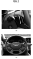
- FIG. 2 is an exemplary diagram illustrating switches included in a steering wheel in order to select a steering mode transition operation in FIG. 1 .
- the apparatus for controlling a 4-wheel independent steering system includes a sensor module 110, a storage module 120, a processor 130, a front wheel driving module 140, a rear wheel driving module 150, and a switch module 160.
- the sensor module 110 may include a current sensor (i.e., a current detection sensor) and a steering angle sensor (i.e., a steering angle detection sensor).
- a current sensor i.e., a current detection sensor
- a steering angle sensor i.e., a steering angle detection sensor
- the sensor module 110 may include wheel speed sensors included in front wheels and rear wheels, respectively, and an acceleration sensor for detecting the acceleration of a vehicle.
- the sensor module 110 may sense information related to an operation of the vehicle, such as braking.
- the processor 130 may measure a steering angle speed by using the steering angle sensor.
- the processor 130 performs a steering mode transition operation of a 4-wheel independent steering system in response to the selection of each switch (e.g., a first switch or a second switch) of the switch module 160.
- each switch e.g., a first switch or a second switch
- the processor 130 may calculate a target yaw rate value that is targeted by a driver, based on a steering angle when the driver performs steering, a driving direction, and a vehicle speed when the driver steps on an accelerator. At this time, driving forces may be optimally distributed to left rear wheels or right rear wheels in accordance with a target yaw rate value, and may be distributed by using a closed loop controller.
- the storage module 120 stores an algorithm for the processor 130 to control the driving forces of the rear wheels and information (or data) detected through the sensor module 110.
- the storage module 120 and the processor 130 may be implemented as separate chips, or may be implemented as a single chip having a form in which the storage module 120 is included in the processor 130.
- the storage module 120 may be implemented as at least one of storage media, such as a cache, a nonvolatile memory device such as read only memory (ROM), programmable ROM (PROM), erasable programmable ROM (EPROM), electrically erasable programmable ROM (EEPROM), or flash memory, a volatile memory device such as random access memory (RAM), a hard disk drive (HDD), or CD-ROM, but the present disclosure is not limited thereto.
- storage media such as a cache, a nonvolatile memory device such as read only memory (ROM), programmable ROM (PROM), erasable programmable ROM (EPROM), electrically erasable programmable ROM (EEPROM), or flash memory, a volatile memory device such as random access memory (RAM), a hard disk drive (HDD), or CD-ROM, but the present disclosure is not limited thereto.
- storage media such as a cache, a nonvolatile memory device such as read only memory (ROM), programmable ROM (PROM),
- the processor 130 may be implemented as an electronic control unit (ECU) for controlling the driving of the vehicle.
- ECU electronice control unit
- the front wheel driving module 140 is connected to front wheels FW1 and FW2, and may drive the actuators (e.g., actuators that adjust rotation directions, rotation speeds, and steering angles of the front wheels by a motor or oil pressure) of the front wheels FW1 and FW2 under the control of the processor 130.
- actuators e.g., actuators that adjust rotation directions, rotation speeds, and steering angles of the front wheels by a motor or oil pressure
- the front wheel driving module 140 may be included in the processor 130.
- the rear wheel driving module 150 is connected to rear wheels RW1 and RW2, and may drive the actuators (e.g., actuators that adjust rotation directions, rotation speeds, and steering angles of the rear wheels by a motor or oil pressure) of the rear wheels RW1 and RW2 under the control of the processor 130.
- actuators e.g., actuators that adjust rotation directions, rotation speeds, and steering angles of the rear wheels by a motor or oil pressure
- the rear wheel driving module 150 may be included in the processor 130.
- the processor 130 may control steering angles of the front wheels and the rear wheels identically or differently by controlling the front wheel driving module 140 and the rear wheel driving module 150.
- the switch module 160 includes a plurality of switches (or buttons) (e.g., a first switch and a second switch) included in a steering wheel (refer to FIG. 2 ).
- switches or buttons
- the switches (e.g., the first switch and the second switch) of the switch module 160 may be provided on the left and right sides, respectively, on the basis of the central axis of the steering wheel.
- the first switch i.e., a left control switch (LCS)
- the second switch i.e., a right control switch (PCS)
- PCS right control switch
- FIG. 3 is a flowchart for illustrating a steering mode transition operation according to the selection of the first switch (LCS) according to a first embodiment of the present disclosure.
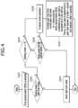
- FIG. 4 is a flowchart for illustrating a steering mode transition operation according to the selection of the second switch (RCS) according to a second embodiment of the present disclosure.
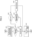
- FIG. 5 is a flowchart for illustrating a steering mode transition operation according to the selection of the first switch (LCS) and the second switch (RCS) according to a third embodiment of the present disclosure.
- the left crab mode is entered when the first switch (LCS) is selected in the state in which a driver steps on the brake pedal and a condition in which the vehicle speed is 0.
- LCD first switch
- the processor 130 When only the first switch (LCS) is selected (S101), if the existing mode (i.e., a steering mode that is maintained so far) is neither the left crab mode (N in S102) nor the neutral (N) mode (N in S104), the processor 130 performs an operation of transition to a reverse phase mode (i.e., a mode in which the front wheels and the rear wheels are controlled to have a reverse phase) (S106).
- a reverse phase mode i.e., a mode in which the front wheels and the rear wheels are controlled to have a reverse phase
- the reverse phase mode is a mode in which the front wheels and the rear wheels are controlled to have the reverse phase.
- the operation of transition to the reverse phase mode includes performing an operation of decreasing a gear ratio from a current gear ratio state to -1 during the time for which the first switch (LCS) is selected.
- the gear ratio is decreased by 0.1 per 200 ms. That is, if the gear ratio is started from 0, an operation of the gear ratio reaching -0.5 after 1 second and reaching -1 after 2 seconds is performed. In this case, it is important that the amount in which the phase of the gear ratio is changed into the reverse phase is determined by the time for which the first switch is held.
- the right crab mode is entered when the second switch (RCS) is selected in the state in which a driver steps on the brake pedal and a condition in which the vehicle speed is 0.
- RCS second switch
- the processor 130 When only the second switch (RCS) is selected (S201), if the existing mode (i.e., a steering mode that is maintained so far) is neither the right crab mode (N in S202) nor the neutral (N) mode (N in S204), the processor 130 performs an operation of transition to an in-phase mode (i.e., a mode in which the front wheels and the rear wheels are controlled to have the same phase) (S206).
- an in-phase mode i.e., a mode in which the front wheels and the rear wheels are controlled to have the same phase
- the in-phase mode is a mode in which the front wheels and the rear wheels are controlled to have the same phase.
- the operation of transition to the in-phase mode includes performing an operation of increasing the gear ratio from a current gear ratio state to 1 during the time for which the second switch (RCS) is selected.
- the gear ratio is increased by 0.1 per 200 ms. That is, if the gear ratio is started from 0, an operation of the gear ratio reaching 0.5 after 1 second and reaching 1 after 2 seconds is performed. In this case, it is important that the amount in which the gear ratio is changed to have the same phase is determined by the time for which the second switch is held.
- the processor 130 continues to enter (i.e., maintain) the spin mode (S303).
- the spin mode is entered when the first switch (LCS) and the second switch (RCS) are simultaneously selected in the state in which a driver has stepped on the brake pedal and a condition in which the vehicle speed is 0.
- the rotation direction is determined when the steering wheel is turned to the left (or right).
- the processor 130 When the first switch (LCS) and the second switch (RCS) are simultaneously selected (S301), if the existing mode (i.e., the steering mode that is maintained so far) is neither the spin mode (N in S302) nor the neutral (N) mode (N in S304), the processor 130 performs an operation of transition to a dynamic 4WS mode (S306).
- the existing mode i.e., the steering mode that is maintained so far
- the processor 130 performs an operation of transition to a dynamic 4WS mode (S306).
- the dynamic 4WS mode is a mode in which the gear ratios of the front wheels and the rear wheels are varied in response to a steering angle speed or angular acceleration.
- the dynamic 4WS mode is transitioned when the first switch (LCS) and the second switch (PCS) are simultaneously selected in the state in which a vehicle speed is present.
- a spin operation i.e., the spin mode is performed in a corresponding direction (S307).
- the spin operation i.e., the spin mode
- FIG. 6 is an exemplary diagram for describing an operating method of the dynamic 4WS mode in FIG. 5 .
- the processor 130 controls the angle of the rear wheels to the front wheels by varying a targeted yaw rate in response to a steering angle speed or steering angular acceleration. That is, the amount of error of a yaw rate that is sensed in a vehicle and that is fed back is made 0 through closed loop control, in other words, a tracking controller by applying an Ref model, that is, an equation for the targeted yaw rate, so that a difference between the targeted yaw rate and the feedback yaw rate becomes 0.
- an Ref model that is, an equation for the targeted yaw rate
- the sensed yaw rate is filtered by applying a low pass filter (LPF) because the value of the sensed yaw rate includes severe noise.
- LPF low pass filter
- variable steer gradient K vs is determined by yaw acceleration, and depends on steering angular acceleration.
- the existing under-steer gradient K us is applied as the variable steer gradient K vs , thereby enabling dynamic 4WS control.
- an embodiment of the present disclosure has an effect in that a steering mode transition operation of the 4-wheel independent steering system can be conveniently performed by using a smaller number of switches than the existing number of switches. Furthermore, an embodiment of the present disclosure has effects in that a steering mode transition operation can be performed by using the switches included in a steering wheel and the steering mode can be organizationally transitioned without a collision between steering modes of the 4-wheel independent steering system.
Landscapes
- Engineering & Computer Science (AREA)
- Chemical & Material Sciences (AREA)
- Combustion & Propulsion (AREA)
- Transportation (AREA)
- Mechanical Engineering (AREA)
- Physics & Mathematics (AREA)
- Mathematical Physics (AREA)
- Theoretical Computer Science (AREA)
- Steering Control In Accordance With Driving Conditions (AREA)
- Steering-Linkage Mechanisms And Four-Wheel Steering (AREA)
Abstract
Description
- This application claims priority from and the benefit of
Korean Patent Application No. 10-2023-0078790, filed on June 20, 2023 - Exemplary embodiments of the present disclosure relate to an apparatus and method for controlling a 4-wheel independent steering system, and more particularly, to an apparatus and method for controlling a 4-wheel independent steering system, which enable a steering mode transition operation of a 4-wheel independent steering system to be performed.
- Recently, an in-wheel motor system in which a motor is embedded in each of four wheels of a vehicle and the four wheels can be independently driven is developed.
- There is an advantage in that more flexible and various driving performance can be provided by implementing a 4-wheel independent driving and 4-wheel independent steering system by organizationally coupling such an in-wheel motor system with a vehicle.
- In the existing common vehicle, the direction of progress of the vehicle is changed by steering only front wheels. In this case, the direction of progress of the vehicle and a driver's gaze direction are not matched with each other because timing at which a lateral force of the front wheels occurs and timing at which a lateral force of rear wheels occurs are different from each other. However, a 4-wheel independent steering system reduces a radius of rotation of a vehicle upon parking or low-speed turn by also applying the steering system to the rear wheels, and improves driving stability when the direction of the vehicle is turned during high-speed driving.
- Conventionally, a steering mode transition operation is performed by installing a plurality of switches corresponding to modes (e.g., a left crab mode (i.e., a left right-angle driving mode), a right crab mode (i.e., a right right-angle driving mode), a spin mode, a reverse phase mode, an in-phase mode, and a gear ratio variable mode) of a 4-wheel independent steering system, respectively, and manipulating a corresponding switch.
- Accordingly, there are problems in that many spaces for installing the switches are required and a driver may feel confused in selecting a switch corresponding to a mode.
- Accordingly, there is a need for a method capable of conveniently performing a steering mode transition operation of a 4-wheel independent steering system by using a smaller number of switches than the existing number of switches.
- The Background Art of the present disclosure is disclosed in
Korean Patent No. 10-2274120 (registered on July 1, 2021 - Various embodiments are directed to providing an apparatus and method for controlling a 4-wheel independent steering system, which enable a steering mode transition operation of a 4-wheel independent steering system to be performed.
- In an embodiment, an apparatus for controlling a 4-wheel independent steering system includes a sensor module, a switch module including a plurality of switches for receiving an instruction for the transition of a steering mode of the 4-wheel independent steering system, and a processor configured to perform a steering mode transition operation of the 4-wheel independent steering system based on a combination of the switches of the switch module.
- In an embodiment of the present disclosure, the switch module includes a first switch and a second switch included in a steering wheel.
- In an embodiment of the present disclosure, the switches of the switch module are provided on left and right sides, respectively, on the basis of a central axis of a steering wheel.
- In an embodiment of the present disclosure, the processor continues to maintain a left crab mode if a steering mode that is maintained so far is the left crab mode when only a first switch (LCS) is selected, enters a left crab mode if a steering mode that is maintained so far is not the left crab mode and is a neutral (N) mode, a brake pedal has been stepped on (Brake Pedal ON), and a vehicle is not in a driving state (a vehicle speed==0), when only the first switch (LCS) is selected, and performs an operation of transition to a reverse phase mode if a steering mode that is maintained so far is neither the left crab mode nor the neutral (N) mode when only the first switch (LCS) is selected.
- In an embodiment of the present disclosure, the reverse phase mode is a mode in which front wheels and rear wheels are controlled to have a reverse phase. The operation of transition to the reverse phase mode is a mode in which an operation of decreasing a gear ratio from a current gear ratio state to -1 is performed during the time for which the first switch (LCS) is selected.
- In an embodiment of the present disclosure, the processor continues to maintain a right crab mode if a steering mode that is maintained so far is the right crab mode when only the second switch (PCS) is selected, enters the right crab mode if a steering mode that is maintained so far is not the right crab mode and is a neutral (N) mode, a brake pedal has been stepped on (Brake Pedal ON), and a vehicle is not in a driving state when only the second switch (RCS) is selected, and performs an operation of transition to an in-phase mode if a steering mode that is maintained so far is neither the right crab mode nor the neutral (N) mode when only the second switch (RCS) is selected.
- In an embodiment of the present disclosure, the in-phase mode is a mode in which front wheels and rear wheels are controlled to have the same phase. The operation of transition to the in-phase mode is a mode in which an operation of increasing a gear ratio from a current gear ratio state to 1 is performed during the time for which the second switch (RCS) is selected.
- In an embodiment of the present disclosure, the processor continues to maintain a spin mode when a steering mode that is maintained so far is the spin mode when the first switch (LCS) and the second switch (RCS) are simultaneously selected, enters the spin mode if a steering mode that is maintained so far is not the spin mode and is a neutral (N) mode, a brake pedal has been stepped on (Brake Pedal ON), and a vehicle is not in a driving state (a vehicle speed==0) when the first switch (LCS) and the second switch (RCS) are simultaneously selected, and performs an operation of transition to a dynamic 4WS mode if a steering mode that is maintained so far is neither the spin mode nor the neutral (N) mode when the first switch (LCS) and the second switch (RCS) are simultaneously selected.
- In an embodiment of the present disclosure, the dynamic 4WS mode is a mode in which gear ratios of front wheels and rear wheels are varied in response to a steering angle speed or angular acceleration, and is a mode in which a spin operation is performed in a corresponding direction when a steering wheel is turned left or right at a specific angle (ⓐ) or more upon operation of transition to the spin mode or the dynamic 4WS mode.
- In an embodiment, a method of controlling a 4-wheel independent steering system includes receiving, by a processor, an instruction for transition of a steering mode of the 4-wheel independent steering system through a plurality of switches of a switch module, and performing, by the processor, a steering mode transition operation of the 4-wheel independent steering system based on a combination of the switches of the switch module.
- According to an embodiment of the present disclosure, a steering mode transition operation of the 4-wheel independent steering system can be conveniently performed by using a smaller number of switches than the existing number of switches.
- Furthermore, according to an embodiment of the present disclosure, a steering mode transition operation can be performed by using the switches included in the steering wheel.
- Furthermore, according to an embodiment of the present disclosure, the transition of steering modes of the 4-wheel independent steering system can be organizationally performed without colliding against each other.
-
-
FIG. 1 is an exemplary diagram illustrating a schematic construction of an apparatus for controlling a 4-wheel independent steering system according to an embodiment of the present disclosure. -
FIG. 2 is an exemplary diagram illustrating switches included in a steering wheel in order to select a steering mode transition operation inFIG. 1 . -
FIG. 3 is a flowchart for illustrating a steering mode transition operation according to the selection of a first switch (LCS) according to a first embodiment of the present disclosure. -
FIG. 4 is a flowchart for illustrating a steering mode transition operation according to the selection of a second switch (PCS) according to a second embodiment of the present disclosure. -
FIG. 5 is a flowchart for illustrating a steering mode transition operation according to the selection of the first switch (LCS) and the second switch (PCS) according to a third embodiment of the present disclosure. -
FIG. 6 is an exemplary diagram for describing an operating method of a dynamic 4WS mode inFIG. 5 . - The components described in the example embodiments may be implemented by hardware components including, for example, at least one digital signal processor (DSP), a processor, a controller, an application-specific integrated circuit (ASIC), a programmable logic element, such as an FPGA, other electronic devices, or combinations thereof. At least some of the functions or the processes described in the example embodiments may be implemented by software, and the software may be recorded on a recording medium. The components, the functions, and the processes described in the example embodiments may be implemented by a combination of hardware and software.
- The method according to example embodiments may be embodied as a program that is executable by a computer, and may be implemented as various recording media such as a magnetic storage medium, an optical reading medium, and a digital storage medium.
- Various techniques described herein may be implemented as digital electronic circuitry, or as computer hardware, firmware, software, or combinations thereof. The techniques may be implemented as a computer program product, i.e., a computer program tangibly embodied in an information carrier, e.g., in a machine-readable storage device (for example, a computer-readable medium) or in a propagated signal for processing by, or to control an operation of a data processing apparatus, e.g., a programmable processor, a computer, or multiple computers. A computer program(s) may be written in any form of a programming language, including compiled or interpreted languages and may be deployed in any form including a stand-alone program or a module, a component, a subroutine, or other units suitable for use in a computing environment. A computer program may be deployed to be executed on one computer or on multiple computers at one site or distributed across multiple sites and interconnected by a communication network.
- Processors suitable for execution of a computer program include, by way of example, both general and special purpose microprocessors, and any one or more processors of any kind of digital computer. Generally, a processor will receive instructions and data from a read-only memory or a random access memory or both. Elements of a computer may include at least one processor to execute instructions and one or more memory devices to store instructions and data. Generally, a computer will also include or be coupled to receive data from, transfer data to, or perform both on one or more mass storage devices to store data, e.g., magnetic, magneto-optical disks, or optical disks. Examples of information carriers suitable for embodying computer program instructions and data include semiconductor memory devices, for example, magnetic media such as a hard disk, a floppy disk, and a magnetic tape, optical media such as a compact disk read only memory (CD-ROM), a digital video disk (DVD), etc. and magneto-optical media such as a floptical disk, and a read only memory (ROM), a random access memory (RAM), a flash memory, an erasable programmable ROM (EPROM), and an electrically erasable programmable ROM (EEPROM) and any other known computer readable medium. A processor and a memory may be supplemented by, or integrated into, a special purpose logic circuit.
- The processor may run an operating system (OS) and one or more software applications that run on the OS. The processor device also may access, store, manipulate, process, and create data in response to execution of the software. For purpose of simplicity, the description of a processor device is used as singular; however, one skilled in the art will be appreciated that a processor device may include multiple processing elements and/or multiple types of processing elements. For example, a processor device may include multiple processors or a processor and a controller. In addition, different processing configurations are possible, such as parallel processors.
- Also, non-transitory computer-readable media may be any available media that may be accessed by a computer, and may include both computer storage media and transmission media.
- The present specification includes details of a number of specific implements, but it should be understood that the details do not limit any invention or what is claimable in the specification but rather describe features of the specific example embodiment. Features described in the specification in the context of individual example embodiments may be implemented as a combination in a single example embodiment. In contrast, various features described in the specification in the context of a single example embodiment may be implemented in multiple example embodiments individually or in an appropriate sub-combination. Furthermore, the features may operate in a specific combination and may be initially described as claimed in the combination, but one or more features may be excluded from the claimed combination in some cases, and the claimed combination may be changed into a sub-combination or a modification of a sub-combination.
- Similarly, even though operations are described in a specific order on the drawings, it should not be understood as the operations needing to be performed in the specific order or in sequence to obtain desired results or as all the operations needing to be performed. In a specific case, multitasking and parallel processing may be advantageous. In addition, it should not be understood as requiring a separation of various apparatus components in the above described example embodiments in all example embodiments, and it should be understood that the above-described program components and apparatuses may be incorporated into a single software product or may be packaged in multiple software products.
- It should be understood that the example embodiments disclosed herein are merely illustrative and are not intended to limit the scope of the invention. It will be apparent to one of ordinary skill in the art that various modifications of the example embodiments may be made without departing from the spirit and scope of the claims and their equivalents.
- Hereinafter, with reference to the accompanying drawings, embodiments of the present disclosure will be described in detail so that a person skilled in the art can readily carry out the present disclosure. However, the present disclosure may be embodied in many different forms and is not limited to the embodiments described herein.
- In the following description of the embodiments of the present disclosure, a detailed description of known functions and configurations incorporated herein will be omitted when it may make the subject matter of the present disclosure rather unclear. Parts not related to the description of the present disclosure in the drawings are omitted, and like parts are denoted by similar reference numerals.
- In the present disclosure, components that are distinguished from each other are intended to clearly illustrate each feature. However, it does not necessarily mean that the components are separate. That is, a plurality of components may be integrated into one hardware or software unit, or a single component may be distributed into a plurality of hardware or software units. Thus, unless otherwise noted, such integrated or distributed embodiments are also included within the scope of the present disclosure.
- In the present disclosure, components described in the various embodiments are not necessarily essential components, and some may be optional components. Accordingly, embodiments consisting of a subset of the components described in one embodiment are also included within the scope of the present disclosure. In addition, embodiments that include other components in addition to the components described in the various embodiments are also included in the scope of the present disclosure.
- Hereinafter, with reference to the accompanying drawings, embodiments of the present disclosure will be described in detail so that a person skilled in the art can readily carry out the present disclosure. However, the present disclosure may be embodied in many different forms and is not limited to the embodiments described herein.
- In the following description of the embodiments of the present disclosure, a detailed description of known functions and configurations incorporated herein will be omitted when it may make the subject matter of the present disclosure rather unclear. Parts not related to the description of the present disclosure in the drawings are omitted, and like parts are denoted by similar reference numerals.
- In the present disclosure, when a component is referred to as being "linked," "coupled," or "connected" to another component, it is understood that not only a direct connection relationship but also an indirect connection relationship through an intermediate component may also be included. In addition, when a component is referred to as "comprising" or "having" another component, it may mean further inclusion of another component not the exclusion thereof, unless explicitly described to the contrary.
- In the present disclosure, the terms first, second, etc. are used only for the purpose of distinguishing one component from another, and do not limit the order or importance of components, etc., unless specifically stated otherwise. Thus, within the scope of this disclosure, a first component in one exemplary embodiment may be referred to as a second component in another embodiment, and similarly a second component in one exemplary embodiment may be referred to as a first component.
- In the present disclosure, components that are distinguished from each other are intended to clearly illustrate each feature. However, it does not necessarily mean that the components are separate. That is, a plurality of components may be integrated into one hardware or software unit, or a single component may be distributed into a plurality of hardware or software units. Thus, unless otherwise noted, such integrated or distributed embodiments are also included within the scope of the present disclosure.
- In the present disclosure, components described in the various embodiments are not necessarily essential components, and some may be optional components. Accordingly, embodiments consisting of a subset of the components described in one embodiment are also included within the scope of the present disclosure. In addition, exemplary embodiments that include other components in addition to the components described in the various embodiments are also included in the scope of the present disclosure.
- Hereinafter, an apparatus and method for controlling a 4-wheel independent steering system according to embodiments of the present disclosure will be described with reference to the accompanying drawings.
- In this process, the thicknesses of lines or the sizes of components illustrated in the drawings may have been exaggerated for the clarity of a description and for convenience' sake. Furthermore, terms to be described below have been defined by taking into consideration their functions in the present disclosure, and may be changed depending on a user or operator's intention or practice. Accordingly, such terms should be defined based on the overall contents of this specification.
-
FIG. 1 is an exemplary diagram illustrating a schematic construction of an apparatus for controlling a 4-wheel independent steering system according to an embodiment of the present disclosure.FIG. 2 is an exemplary diagram illustrating switches included in a steering wheel in order to select a steering mode transition operation inFIG. 1 . - As illustrated in
FIG. 1 , the apparatus for controlling a 4-wheel independent steering system according to the present embodiment includes asensor module 110, astorage module 120, aprocessor 130, a frontwheel driving module 140, a rearwheel driving module 150, and aswitch module 160. - The
sensor module 110 may include a current sensor (i.e., a current detection sensor) and a steering angle sensor (i.e., a steering angle detection sensor). - The
sensor module 110 may include wheel speed sensors included in front wheels and rear wheels, respectively, and an acceleration sensor for detecting the acceleration of a vehicle. - The
sensor module 110 may sense information related to an operation of the vehicle, such as braking. - The
processor 130 may measure a steering angle speed by using the steering angle sensor. - The
processor 130 performs a steering mode transition operation of a 4-wheel independent steering system in response to the selection of each switch (e.g., a first switch or a second switch) of theswitch module 160. - The
processor 130 may calculate a target yaw rate value that is targeted by a driver, based on a steering angle when the driver performs steering, a driving direction, and a vehicle speed when the driver steps on an accelerator. At this time, driving forces may be optimally distributed to left rear wheels or right rear wheels in accordance with a target yaw rate value, and may be distributed by using a closed loop controller. - The
storage module 120 stores an algorithm for theprocessor 130 to control the driving forces of the rear wheels and information (or data) detected through thesensor module 110. - In this case, the
storage module 120 and theprocessor 130 may be implemented as separate chips, or may be implemented as a single chip having a form in which thestorage module 120 is included in theprocessor 130. - Furthermore, the
storage module 120 may be implemented as at least one of storage media, such as a cache, a nonvolatile memory device such as read only memory (ROM), programmable ROM (PROM), erasable programmable ROM (EPROM), electrically erasable programmable ROM (EEPROM), or flash memory, a volatile memory device such as random access memory (RAM), a hard disk drive (HDD), or CD-ROM, but the present disclosure is not limited thereto. - Furthermore, the
processor 130 may be implemented as an electronic control unit (ECU) for controlling the driving of the vehicle. - The front
wheel driving module 140 is connected to front wheels FW1 and FW2, and may drive the actuators (e.g., actuators that adjust rotation directions, rotation speeds, and steering angles of the front wheels by a motor or oil pressure) of the front wheels FW1 and FW2 under the control of theprocessor 130. - The front
wheel driving module 140 may be included in theprocessor 130. - The rear
wheel driving module 150 is connected to rear wheels RW1 and RW2, and may drive the actuators (e.g., actuators that adjust rotation directions, rotation speeds, and steering angles of the rear wheels by a motor or oil pressure) of the rear wheels RW1 and RW2 under the control of theprocessor 130. - The rear
wheel driving module 150 may be included in theprocessor 130. - Furthermore, the
processor 130 may control steering angles of the front wheels and the rear wheels identically or differently by controlling the frontwheel driving module 140 and the rearwheel driving module 150. - The
switch module 160 includes a plurality of switches (or buttons) (e.g., a first switch and a second switch) included in a steering wheel (refer toFIG. 2 ). - The switches (e.g., the first switch and the second switch) of the
switch module 160 may be provided on the left and right sides, respectively, on the basis of the central axis of the steering wheel. - For example, referring to
FIG. 2 , the first switch (i.e., a left control switch (LCS)) may be provided on the left side of the steering wheel. The second switch (i.e., a right control switch (PCS)) may be provided on the right side of the steering wheel. - Hereinafter, a steering mode transition operation of the
processor 130 is described with reference to the flowcharts ofFIGS. 3 to 5 . -
FIG. 3 is a flowchart for illustrating a steering mode transition operation according to the selection of the first switch (LCS) according to a first embodiment of the present disclosure.FIG. 4 is a flowchart for illustrating a steering mode transition operation according to the selection of the second switch (RCS) according to a second embodiment of the present disclosure.FIG. 5 is a flowchart for illustrating a steering mode transition operation according to the selection of the first switch (LCS) and the second switch (RCS) according to a third embodiment of the present disclosure. - Referring to
FIG. 3 , when only the first switch (LCS) is selected (S101), if the existing mode (i.e., a steering mode that is maintained so far) is a left crab mode (Y (Yes) in S102), theprocessor 130 continues to enter (i.e., maintain) the left crab mode (S103). - When only the first switch (LCS) is selected (S101), if the existing mode (i.e., a steering mode that is maintained so far) is not the left crab mode (N (No) in S102) and is a neutral (N) mode, a brake pedal has been stepped on (Brake Pedal ON), and the vehicle is not in a driving state (i.e., a vehicle speed==0) (Y in S105), the
processor 130 enters the left crab mode (S103). - That is, the left crab mode is entered when the first switch (LCS) is selected in the state in which a driver steps on the brake pedal and a condition in which the vehicle speed is 0.
- When only the first switch (LCS) is selected (S101), if the existing mode (i.e., a steering mode that is maintained so far) is neither the left crab mode (N in S102) nor the neutral (N) mode (N in S104), the
processor 130 performs an operation of transition to a reverse phase mode (i.e., a mode in which the front wheels and the rear wheels are controlled to have a reverse phase) (S106). - In this case, the reverse phase mode is a mode in which the front wheels and the rear wheels are controlled to have the reverse phase. The operation of transition to the reverse phase mode includes performing an operation of decreasing a gear ratio from a current gear ratio state to -1 during the time for which the first switch (LCS) is selected. For example, the gear ratio is decreased by 0.1 per 200 ms. That is, if the gear ratio is started from 0, an operation of the gear ratio reaching -0.5 after 1 second and reaching -1 after 2 seconds is performed. In this case, it is important that the amount in which the phase of the gear ratio is changed into the reverse phase is determined by the time for which the first switch is held.
- Referring to
FIG. 4 , when only the second switch (PCS) is selected (S201), if the existing mode (i.e., a steering mode that is maintained so far) is a right crab mode (Y in S202), theprocessor 130 continues to enter (i.e., maintain) the right crab mode (S203). - When only the second switch (RCS) is selected (S201), if the existing mode (i.e., a steering mode that is maintained so far) is not the right crab mode (N in S202) and is the neutral (N) mode, the brake pedal has been stepped on (Brake Pedal ON), and the vehicle is not in the driving state (i.e., a vehicle speed==0) (Y in S205), the
processor 130 enters the right crab mode (S203). - That is, the right crab mode is entered when the second switch (RCS) is selected in the state in which a driver steps on the brake pedal and a condition in which the vehicle speed is 0.
- When only the second switch (RCS) is selected (S201), if the existing mode (i.e., a steering mode that is maintained so far) is neither the right crab mode (N in S202) nor the neutral (N) mode (N in S204), the
processor 130 performs an operation of transition to an in-phase mode (i.e., a mode in which the front wheels and the rear wheels are controlled to have the same phase) (S206). - In this case, the in-phase mode is a mode in which the front wheels and the rear wheels are controlled to have the same phase. The operation of transition to the in-phase mode includes performing an operation of increasing the gear ratio from a current gear ratio state to 1 during the time for which the second switch (RCS) is selected. For example, the gear ratio is increased by 0.1 per 200 ms. That is, if the gear ratio is started from 0, an operation of the gear ratio reaching 0.5 after 1 second and reaching 1 after 2 seconds is performed. In this case, it is important that the amount in which the gear ratio is changed to have the same phase is determined by the time for which the second switch is held.
- Referring to
FIG. 5 , when the first switch (LCS) and the second switch (RCS) are simultaneously selected (S301), if the existing mode (i.e., a steering mode that is maintained so far) is a spin mode (Y in S302), theprocessor 130 continues to enter (i.e., maintain) the spin mode (S303). - When the first switch (LCS) and the second switch (RCS) are simultaneously selected (S301), if the existing mode (i.e., a steering mode that is maintained so far) is not the spin mode (N in S302) and is the neutral (N) mode (Y in S304), the brake pedal has been stepped on (Brake Pedal ON), and the vehicle is not in the driving state (i.e., a vehicle speed==0) (Y in S305), the
processor 130 enters the spin mode (S303). - That is, the spin mode is entered when the first switch (LCS) and the second switch (RCS) are simultaneously selected in the state in which a driver has stepped on the brake pedal and a condition in which the vehicle speed is 0. In this case, the rotation direction is determined when the steering wheel is turned to the left (or right).
- When the first switch (LCS) and the second switch (RCS) are simultaneously selected (S301), if the existing mode (i.e., the steering mode that is maintained so far) is neither the spin mode (N in S302) nor the neutral (N) mode (N in S304), the
processor 130 performs an operation of transition to a dynamic 4WS mode (S306). - In this case, the dynamic 4WS mode is a mode in which the gear ratios of the front wheels and the rear wheels are varied in response to a steering angle speed or angular acceleration. The dynamic 4WS mode is transitioned when the first switch (LCS) and the second switch (PCS) are simultaneously selected in the state in which a vehicle speed is present.
- In this case, upon operation of transition to the spin mode or the dynamic 4WS mode, when the steering wheel is turned to the left (or right) by a specific angle (ⓐ) or more, a spin operation (i.e., the spin mode) is performed in a corresponding direction (S307).
- For example, when the specific angle (ⓐ) is 10 degrees and the steering wheel is turned -15 degrees (i.e., to the left), the spin operation (i.e., the spin mode) is performed to the left.
- For reference,
FIG. 6 is an exemplary diagram for describing an operating method of the dynamic 4WS mode inFIG. 5 . - Referring to
FIG. 6 , upon operation in the dynamic 4WS mode, theprocessor 130 controls the angle of the rear wheels to the front wheels by varying a targeted yaw rate in response to a steering angle speed or steering angular acceleration. That is, the amount of error of a yaw rate that is sensed in a vehicle and that is fed back is made 0 through closed loop control, in other words, a tracking controller by applying an Ref model, that is, an equation for the targeted yaw rate, so that a difference between the targeted yaw rate and the feedback yaw rate becomes 0. - In this case, the sensed yaw rate is filtered by applying a low pass filter (LPF) because the value of the sensed yaw rate includes severe noise.
- In this case, it is important that noise is filtered out from the sensed yaw rate, that is, the fed-back yaw rate, through the LPF or a Kalman filter. In the dynamic 4WS mode, all of over, neutral, and under-steer operations are performed based on a steering propensity of a driver, that is, a steering angle speed or angular acceleration, by applying a variable gradient Kvs to an actual final yaw rate reference value without applying the existing under-steer gradient Kus through the following equation based on a value of the sensed yaw rate.





wherein Kus means an under-steer gradient, Kvs means a variable steer gradient, V means a vehicle speed, L means a vehicle wheel base length, g means gravity acceleration, δf means a front wheel steering angle , δr means a rear wheel steering angle, Cf means cornering stiffness of a front wheel, Cr means cornering stiffness of a rear wheel, lz means inertia moment of the vehicle, Fyf means a lateral force of a front wheel, Fyr means a lateral force of the rear wheel, R means a radius of rotation, ay means lateral acceleration, and m means vehicle weight. - An operation of the final yaw rate in the dynamic 4WS mode may be known through the deployment of the equation as described above. As a result, the variable steer gradient Kvs is determined by yaw acceleration, and depends on steering angular acceleration. In other words, in the present embodiment, the existing under-steer gradient Kus is applied as the variable steer gradient Kvs, thereby enabling dynamic 4WS control.
- As described above, an embodiment of the present disclosure has an effect in that a steering mode transition operation of the 4-wheel independent steering system can be conveniently performed by using a smaller number of switches than the existing number of switches. Furthermore, an embodiment of the present disclosure has effects in that a steering mode transition operation can be performed by using the switches included in a steering wheel and the steering mode can be organizationally transitioned without a collision between steering modes of the 4-wheel independent steering system.
Claims (10)
- An apparatus for controlling a 4-wheel independent steering system, the apparatus comprising:a sensor module;a switch module comprising a plurality of switches for receiving an instruction for a transition of a steering mode of the 4-wheel independent steering system; anda processor configured to perform a steering mode transition operation of the 4-wheel independent steering system based on a combination of the switches of the switch module.
- The apparatus of claim 1, wherein the switch module comprises a first switch and a second switch included in a steering wheel.
- The apparatus of claim 1, or 2, wherein the switches of the switch module are provided on left and right sides, respectively, on a basis of a central axis of a steering wheel.
- The apparatus of claim 1, 2, or 3, wherein the processorcontinues to maintain a left crab mode if a steering mode that is maintained so far is the left crab mode when only a first switch (LCS) is selected,enters a left crab mode if a steering mode that is maintained so far is not the left crab mode and is a neutral (N) mode, a brake pedal has been stepped on (Brake Pedal ON), and a vehicle is not in a driving state (a vehicle speed==0), when only the first switch (LCS) is selected, andperforms an operation of transition to a reverse phase mode if a steering mode that is maintained so far is neither the left crab mode nor the neutral (N) mode when only the first switch (LCS) is selected.
- The apparatus of claim 4, wherein:the reverse phase mode is a mode in which front wheels and rear wheels are controlled to have a reverse phase, andthe operation of transition to the reverse phase mode is a mode in which an operation of decreasing a gear ratio from a current gear ratio state to -1 is performed during time for which the first switch (LCS) is selected.
- The apparatus of any one of claims 1 to 5, wherein the processorcontinues to maintain a right crab mode if a steering mode that is maintained so far is the right crab mode when only the second switch (PCS) is selected,enters the right crab mode if a steering mode that is maintained so far is not the right crab mode and is a neutral (N) mode, a brake pedal has been stepped on (Brake Pedal ON), and a vehicle is not in a driving state when only the second switch (RCS) is selected, andperforms an operation of transition to an in-phase mode if a steering mode that is maintained so far is neither the right crab mode nor the neutral (N) mode when only the second switch (RCS) is selected.
- The apparatus of claim 6, wherein:the in-phase mode is a mode in which front wheels and rear wheels are controlled to have an identical phase, andthe operation of transition to the in-phase mode is a mode in which an operation of increasing a gear ratio from a current gear ratio state to 1 is performed during time for which the second switch (RCS) is selected.
- The apparatus of any one of claims 1 to 7, wherein the processorcontinues to maintain a spin mode when a steering mode that is maintained so far is the spin mode when the first switch (LCS) and the second switch (RCS) are simultaneously selected,enters the spin mode if a steering mode that is maintained so far is not the spin mode and is a neutral (N) mode, a brake pedal has been stepped on (Brake Pedal ON), and a vehicle is not in a driving state (a vehicle speed==0) when the first switch (LCS) and the second switch (PCS) are simultaneously selected, andperforms an operation of transition to a dynamic 4WS mode if a steering mode that is maintained so far is neither the spin mode nor the neutral (N) mode when the first switch (LCS) and the second switch (RCS) are simultaneously selected.
- The apparatus of claim 8, wherein the dynamic 4WS mode is a mode in which gear ratios of front wheels and rear wheels are varied in response to a steering angle speed or angular acceleration, and is a mode in which a spin operation is performed in a corresponding direction when a steering wheel is turned left or right at a specific angle (ⓐ) or more upon operation of transition to the spin mode or the dynamic 4WS mode.
- A method of controlling a 4-wheel independent steering system, the method comprising:receiving, by a processor, an instruction for transition of a steering mode of the 4-wheel independent steering system through a plurality of switches of a switch module; andperforming, by the processor, a steering mode transition operation of the 4-wheel independent steering system based on a combination of the switches of the switch module.
Applications Claiming Priority (1)
| Application Number | Priority Date | Filing Date | Title |
|---|---|---|---|
| KR1020230078790A KR20240177433A (en) | 2023-06-20 | 2023-06-20 | Apparatus and method for controlling of 4wheel independent steering system |
Publications (2)
| Publication Number | Publication Date |
|---|---|
| EP4480788A1 true EP4480788A1 (en) | 2024-12-25 |
| EP4480788B1 EP4480788B1 (en) | 2026-02-11 |
Family
ID=88778103
Family Applications (1)
| Application Number | Title | Priority Date | Filing Date |
|---|---|---|---|
| EP23208716.3A Active EP4480788B1 (en) | 2023-06-20 | 2023-11-09 | Apparatus and method for controlling 4-wheel independent steering system |
Country Status (3)
| Country | Link |
|---|---|
| US (1) | US12459566B2 (en) |
| EP (1) | EP4480788B1 (en) |
| KR (1) | KR20240177433A (en) |
Citations (4)
| Publication number | Priority date | Publication date | Assignee | Title |
|---|---|---|---|---|
| US7114591B2 (en) * | 2002-02-27 | 2006-10-03 | Hitachi Construction Machinery Co., Ltd. | Steering system for working truck |
| US20140305715A1 (en) * | 2011-11-28 | 2014-10-16 | Ntn Corporation | Automobile |
| DE102018127929A1 (en) * | 2018-11-08 | 2020-05-14 | Schaeffler Technologies AG & Co. KG | Device for operating a motor vehicle in a user-controlled driving mode |
| KR102274120B1 (en) | 2017-04-12 | 2021-07-07 | 현대자동차주식회사 | Control apparatus and method for rear wheel steering system |
Family Cites Families (1)
| Publication number | Priority date | Publication date | Assignee | Title |
|---|---|---|---|---|
| JP2009241663A (en) * | 2008-03-28 | 2009-10-22 | Iseki & Co Ltd | Working vehicle |
-
2023
- 2023-06-20 KR KR1020230078790A patent/KR20240177433A/en active Pending
- 2023-11-09 EP EP23208716.3A patent/EP4480788B1/en active Active
- 2023-12-04 US US18/527,503 patent/US12459566B2/en active Active
Patent Citations (4)
| Publication number | Priority date | Publication date | Assignee | Title |
|---|---|---|---|---|
| US7114591B2 (en) * | 2002-02-27 | 2006-10-03 | Hitachi Construction Machinery Co., Ltd. | Steering system for working truck |
| US20140305715A1 (en) * | 2011-11-28 | 2014-10-16 | Ntn Corporation | Automobile |
| KR102274120B1 (en) | 2017-04-12 | 2021-07-07 | 현대자동차주식회사 | Control apparatus and method for rear wheel steering system |
| DE102018127929A1 (en) * | 2018-11-08 | 2020-05-14 | Schaeffler Technologies AG & Co. KG | Device for operating a motor vehicle in a user-controlled driving mode |
Also Published As
| Publication number | Publication date |
|---|---|
| KR20240177433A (en) | 2024-12-27 |
| US12459566B2 (en) | 2025-11-04 |
| EP4480788B1 (en) | 2026-02-11 |
| US20240425110A1 (en) | 2024-12-26 |
Similar Documents
| Publication | Publication Date | Title |
|---|---|---|
| CN104703854B (en) | Vehicle motion controls | |
| CN110622230B (en) | Route generation device, vehicle, and vehicle system | |
| US20180297594A1 (en) | Vehicular motion control device and method | |
| US10272944B2 (en) | Steering systems and methods for generating haptic feel torque | |
| US20130110332A1 (en) | System and method for controlling a vehicle using in-wheel system | |
| US7472766B2 (en) | Regeneration control system | |
| EP3409564B1 (en) | System and method for performing parallel parking manuevers with single side braking | |
| CN111959506B (en) | Vehicle and control method and device for vehicle formation running | |
| US20210094560A1 (en) | Vehicle steering backup | |
| US20250145019A1 (en) | Drift and Power Slide Mode for a Vehicle | |
| US11772679B2 (en) | Steer control logic for emergency handling of autonomous vehicles | |
| CN109895845A (en) | The method of the all-wheel control system and operation all-wheel control system of motor vehicles | |
| EP4480788B1 (en) | Apparatus and method for controlling 4-wheel independent steering system | |
| US20250026402A1 (en) | Apparatus for and method of controlling rear-wheel steering | |
| CN115056850B (en) | Auxiliary control method, system, vehicle and medium based on wire control steering | |
| US12195122B2 (en) | Emergency steering control apparatus and method of four wheel independent steering system | |
| US11897560B2 (en) | Road surface impact stimulation device of steer-by-wire system | |
| CN115107742B (en) | Vehicle control method and system and 6×6 vehicle | |
| EP4549289A1 (en) | Apparatus and method for controlling four-wheel independent steering vehicle | |
| EP4470819A1 (en) | Four-wheel independent steering control apparatus and method | |
| US12565214B2 (en) | Apparatus and method for estimating steering angle based on differential braking, and computer-readable storage medium storing program for performing the method | |
| JP2009202770A (en) | Device and method for controlling traveling posture of vehicle | |
| EP4660024A1 (en) | Control apparatus of four-wheel independent control vehicle and method thereof | |
| US20250381979A1 (en) | Systems and methods for dynamic steering of vehicle wheels to follow driving path | |
| CN121268579A (en) | Vehicle auxiliary steering control method based on inner front wheel braking and vehicle |
Legal Events
| Date | Code | Title | Description |
|---|---|---|---|
| PUAI | Public reference made under article 153(3) epc to a published international application that has entered the european phase |
Free format text: ORIGINAL CODE: 0009012 |
|
| STAA | Information on the status of an ep patent application or granted ep patent |
Free format text: STATUS: THE APPLICATION HAS BEEN PUBLISHED |
|
| AK | Designated contracting states |
Kind code of ref document: A1 Designated state(s): AL AT BE BG CH CY CZ DE DK EE ES FI FR GB GR HR HU IE IS IT LI LT LU LV MC ME MK MT NL NO PL PT RO RS SE SI SK SM TR |
|
| STAA | Information on the status of an ep patent application or granted ep patent |
Free format text: STATUS: REQUEST FOR EXAMINATION WAS MADE |
|
| 17P | Request for examination filed |
Effective date: 20250624 |
|
| GRAP | Despatch of communication of intention to grant a patent |
Free format text: ORIGINAL CODE: EPIDOSNIGR1 |
|
| STAA | Information on the status of an ep patent application or granted ep patent |
Free format text: STATUS: GRANT OF PATENT IS INTENDED |
|
| RIC1 | Information provided on ipc code assigned before grant |
Ipc: B62D 7/15 20060101AFI20250910BHEP Ipc: B62D 1/04 20060101ALI20250910BHEP Ipc: B62D 6/00 20060101ALI20250910BHEP |
|
| INTG | Intention to grant announced |
Effective date: 20250924 |
|
| GRAS | Grant fee paid |
Free format text: ORIGINAL CODE: EPIDOSNIGR3 |
|
| GRAA | (expected) grant |
Free format text: ORIGINAL CODE: 0009210 |
|
| STAA | Information on the status of an ep patent application or granted ep patent |
Free format text: STATUS: THE PATENT HAS BEEN GRANTED |
|
| AK | Designated contracting states |
Kind code of ref document: B1 Designated state(s): AL AT BE BG CH CY CZ DE DK EE ES FI FR GB GR HR HU IE IS IT LI LT LU LV MC ME MK MT NL NO PL PT RO RS SE SI SK SM TR |
|
| REG | Reference to a national code |
Ref country code: CH Ref legal event code: F10 Free format text: ST27 STATUS EVENT CODE: U-0-0-F10-F00 (AS PROVIDED BY THE NATIONAL OFFICE) Effective date: 20260211 Ref country code: GB Ref legal event code: FG4D |
|
| P01 | Opt-out of the competence of the unified patent court (upc) registered |
Free format text: CASE NUMBER: UPC_APP_0000964_4480788/2026 Effective date: 20260112 |
|
| REG | Reference to a national code |
Ref country code: DE Ref legal event code: R096 Ref document number: 602023011843 Country of ref document: DE |
|
| REG | Reference to a national code |
Ref country code: IE Ref legal event code: FG4D |
|
| REG | Reference to a national code |
Ref country code: NL Ref legal event code: MP Effective date: 20260211 |
|
| PG25 | Lapsed in a contracting state [announced via postgrant information from national office to epo] |
Ref country code: RS Free format text: LAPSE BECAUSE OF FAILURE TO SUBMIT A TRANSLATION OF THE DESCRIPTION OR TO PAY THE FEE WITHIN THE PRESCRIBED TIME-LIMIT Effective date: 20260511 |
|
| PG25 | Lapsed in a contracting state [announced via postgrant information from national office to epo] |
Ref country code: ES Free format text: LAPSE BECAUSE OF FAILURE TO SUBMIT A TRANSLATION OF THE DESCRIPTION OR TO PAY THE FEE WITHIN THE PRESCRIBED TIME-LIMIT Effective date: 20260211 |
|
| PG25 | Lapsed in a contracting state [announced via postgrant information from national office to epo] |
Ref country code: PL Free format text: LAPSE BECAUSE OF FAILURE TO SUBMIT A TRANSLATION OF THE DESCRIPTION OR TO PAY THE FEE WITHIN THE PRESCRIBED TIME-LIMIT Effective date: 20260211 |
|
| PG25 | Lapsed in a contracting state [announced via postgrant information from national office to epo] |
Ref country code: GR Free format text: LAPSE BECAUSE OF FAILURE TO SUBMIT A TRANSLATION OF THE DESCRIPTION OR TO PAY THE FEE WITHIN THE PRESCRIBED TIME-LIMIT Effective date: 20260512 |
|
| REG | Reference to a national code |
Ref country code: LT Ref legal event code: MG9D |
|
| PG25 | Lapsed in a contracting state [announced via postgrant information from national office to epo] |
Ref country code: LT Free format text: LAPSE BECAUSE OF FAILURE TO SUBMIT A TRANSLATION OF THE DESCRIPTION OR TO PAY THE FEE WITHIN THE PRESCRIBED TIME-LIMIT Effective date: 20260211 |
|
| PG25 | Lapsed in a contracting state [announced via postgrant information from national office to epo] |
Ref country code: NO Free format text: LAPSE BECAUSE OF FAILURE TO SUBMIT A TRANSLATION OF THE DESCRIPTION OR TO PAY THE FEE WITHIN THE PRESCRIBED TIME-LIMIT Effective date: 20260511 |
|
| PG25 | Lapsed in a contracting state [announced via postgrant information from national office to epo] |
Ref country code: FI Free format text: LAPSE BECAUSE OF FAILURE TO SUBMIT A TRANSLATION OF THE DESCRIPTION OR TO PAY THE FEE WITHIN THE PRESCRIBED TIME-LIMIT Effective date: 20260211 Ref country code: AT Free format text: LAPSE BECAUSE OF FAILURE TO SUBMIT A TRANSLATION OF THE DESCRIPTION OR TO PAY THE FEE WITHIN THE PRESCRIBED TIME-LIMIT Effective date: 20260211 Ref country code: SE Free format text: LAPSE BECAUSE OF FAILURE TO SUBMIT A TRANSLATION OF THE DESCRIPTION OR TO PAY THE FEE WITHIN THE PRESCRIBED TIME-LIMIT Effective date: 20260211 |
|
| REG | Reference to a national code |
Ref country code: AT Ref legal event code: MK05 Ref document number: 1885449 Country of ref document: AT Kind code of ref document: T Effective date: 20260211 |
|
| PG25 | Lapsed in a contracting state [announced via postgrant information from national office to epo] |
Ref country code: HR Free format text: LAPSE BECAUSE OF FAILURE TO SUBMIT A TRANSLATION OF THE DESCRIPTION OR TO PAY THE FEE WITHIN THE PRESCRIBED TIME-LIMIT Effective date: 20260211 |
|
| PG25 | Lapsed in a contracting state [announced via postgrant information from national office to epo] |
Ref country code: PT Free format text: LAPSE BECAUSE OF FAILURE TO SUBMIT A TRANSLATION OF THE DESCRIPTION OR TO PAY THE FEE WITHIN THE PRESCRIBED TIME-LIMIT Effective date: 20260611 Ref country code: IS Free format text: LAPSE BECAUSE OF FAILURE TO SUBMIT A TRANSLATION OF THE DESCRIPTION OR TO PAY THE FEE WITHIN THE PRESCRIBED TIME-LIMIT Effective date: 20260611 |
|
| PG25 | Lapsed in a contracting state [announced via postgrant information from national office to epo] |
Ref country code: NL Free format text: LAPSE BECAUSE OF FAILURE TO SUBMIT A TRANSLATION OF THE DESCRIPTION OR TO PAY THE FEE WITHIN THE PRESCRIBED TIME-LIMIT Effective date: 20260211 |
|
| PG25 | Lapsed in a contracting state [announced via postgrant information from national office to epo] |
Ref country code: LV Free format text: LAPSE BECAUSE OF FAILURE TO SUBMIT A TRANSLATION OF THE DESCRIPTION OR TO PAY THE FEE WITHIN THE PRESCRIBED TIME-LIMIT Effective date: 20260211 |
|
| PG25 | Lapsed in a contracting state [announced via postgrant information from national office to epo] |
Ref country code: BG Free format text: LAPSE BECAUSE OF FAILURE TO SUBMIT A TRANSLATION OF THE DESCRIPTION OR TO PAY THE FEE WITHIN THE PRESCRIBED TIME-LIMIT Effective date: 20260211 |