EP4480715A1 - Pneumatic tire - Google Patents
Pneumatic tire Download PDFInfo
- Publication number
- EP4480715A1 EP4480715A1 EP24172609.0A EP24172609A EP4480715A1 EP 4480715 A1 EP4480715 A1 EP 4480715A1 EP 24172609 A EP24172609 A EP 24172609A EP 4480715 A1 EP4480715 A1 EP 4480715A1
- Authority
- EP
- European Patent Office
- Prior art keywords
- tire
- elastic modulus
- complex elastic
- rim
- rubber layer
- Prior art date
- Legal status (The legal status is an assumption and is not a legal conclusion. Google has not performed a legal analysis and makes no representation as to the accuracy of the status listed.)
- Granted
Links
Images


Classifications
-
- B—PERFORMING OPERATIONS; TRANSPORTING
- B60—VEHICLES IN GENERAL
- B60C—VEHICLE TYRES; TYRE INFLATION; TYRE CHANGING; CONNECTING VALVES TO INFLATABLE ELASTIC BODIES IN GENERAL; DEVICES OR ARRANGEMENTS RELATED TO TYRES
- B60C11/00—Tyre tread bands; Tread patterns; Anti-skid inserts
- B60C11/0041—Tyre tread bands; Tread patterns; Anti-skid inserts comprising different tread rubber layers
- B60C11/005—Tyre tread bands; Tread patterns; Anti-skid inserts comprising different tread rubber layers with cap and base layers
-
- B—PERFORMING OPERATIONS; TRANSPORTING
- B60—VEHICLES IN GENERAL
- B60C—VEHICLE TYRES; TYRE INFLATION; TYRE CHANGING; CONNECTING VALVES TO INFLATABLE ELASTIC BODIES IN GENERAL; DEVICES OR ARRANGEMENTS RELATED TO TYRES
- B60C3/00—Tyres characterised by the transverse section
- B60C3/04—Tyres characterised by the transverse section characterised by the relative dimensions of the section, e.g. low profile
-
- B—PERFORMING OPERATIONS; TRANSPORTING
- B60—VEHICLES IN GENERAL
- B60C—VEHICLE TYRES; TYRE INFLATION; TYRE CHANGING; CONNECTING VALVES TO INFLATABLE ELASTIC BODIES IN GENERAL; DEVICES OR ARRANGEMENTS RELATED TO TYRES
- B60C9/00—Reinforcements or ply arrangement of pneumatic tyres
- B60C2009/0071—Reinforcements or ply arrangement of pneumatic tyres characterised by special physical properties of the reinforcements
- B60C2009/0078—Modulus
-
- B—PERFORMING OPERATIONS; TRANSPORTING
- B60—VEHICLES IN GENERAL
- B60C—VEHICLE TYRES; TYRE INFLATION; TYRE CHANGING; CONNECTING VALVES TO INFLATABLE ELASTIC BODIES IN GENERAL; DEVICES OR ARRANGEMENTS RELATED TO TYRES
- B60C11/00—Tyre tread bands; Tread patterns; Anti-skid inserts
- B60C11/0008—Tyre tread bands; Tread patterns; Anti-skid inserts characterised by the tread rubber
- B60C2011/0016—Physical properties or dimensions
- B60C2011/0025—Modulus or tan delta
Definitions
- the present invention relates to a pneumatic tire.
- a tire mounted to the above-described small-size bus is required to have a reduced outer diameter in order to maximize a vehicle cabin space.
- this type of tire receives a high load, excellent wear resistance is required. Further, from the viewpoint of increasing the comfort of the occupant, the tire is also required to provide excellent ride comfort.
- the present invention has been made in view of the above circumstances, and a main object of the present invention is to provide a pneumatic tire which has a specific tire size and has improved wear resistance and ride comfort.
- the present invention is directed to a pneumatic tire to be mounted and used on a rim.
- the rim has a rim diameter RD of 12 to 17 inches.
- a ratio SH/SW of a tire cross-sectional height SH to a tire cross-sectional width SW is 0.30 to 0.45.
- a ratio RW/SW of a rim width RW of the rim to the tire cross-sectional width SW is 0.78 to 0.99.
- the pneumatic tire includes a tread portion.
- the tread portion includes a tread rubber, and a belt layer including two belt plies and disposed inward of the tread rubber in a tire radial direction.
- the tread rubber includes a cap rubber layer forming a ground-contact surface, and a base rubber layer disposed inward of the cap rubber layer in the tire radial direction.
- a complex elastic modulus E* 1 (MPa) of the cap rubber layer is larger than a complex elastic modulus E*2 (MPa) of the base rubber layer.
- a plurality of belt cords having a flexural rigidity M (g cm) are arranged so as to have a number n of the belt cords per ply width of 5 cm.
- the complex elastic modulus E* 1, the complex elastic modulus E*2, the flexural rigidity M, and the number n satisfy a relationship of a following formula (1).
- the pneumatic tire of the present invention has the above-described structure, and thus can improve wear resistance and ride comfort.
- FIG. 1 is a transverse cross-sectional view of a pneumatic tire 1 (hereinafter, may be simply referred to as "tire 1") according to one embodiment of the present invention.
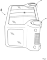
- FIG. 2 is a perspective view conceptually showing a vehicle Ve on which the tires 1 of the present invention are mounted. As shown in FIG. 1 and FIG. 2 , the tire 1 of the present embodiment is mounted and used on a rim R, and is suitably used as a pneumatic tire for the vehicle Ve such as a small-size bus or a small-size shuttle bus, for example.
- the above-described vehicle Ve is a four-wheel automobile.
- the vehicle Ve is not limited to a four-wheel one, and may have six wheels or eight wheels.
- a predetermined number of the tires 1 are mounted to the vehicle Ve according to the wheel structure.
- the vehicle Ve falls under a small-size shuttle bus to be used for transporting people or articles in urban areas, for example.
- a small-size shuttle bus a vehicle having an entire length of 4 m to 7 m, an entire width of about 2 m, and a total vehicle weight of about 3 t is assumed.
- the tire 1 of the present invention may be used for not only the vehicles in the above-described range but also various kinds of vehicles.
- the vehicle Ve may be used not only for transportation of people but also for transportation of articles, and may be further used as a mobile store, a mobile office, or the like.
- the vehicle Ve is preferably an electric automobile having an automatic driving function, for example.
- the vehicle Ve is mainly intended for transporting people, articles, and the like in urban areas, and thus is assumed to have a relatively low running speed range (an average speed of about 50 km/h). Thus, importance need not necessarily be placed on wet performance.
- the vehicle Ve is not limited to such a mode.
- the vehicle Ve is an electric automobile
- a motor is preferably disposed in a rim.
- the vehicle Ve preferably has an independent steering function that allows each wheel to be steered independently. Accordingly, turning or the like is easily performed on the spot, and a vehicle cabin space of the vehicle Ve can be increased.
- the tire 1 of the present embodiment to be used for such a vehicle Ve is required to have a high space efficiency.
- a rim diameter for the tire 1 is required to be small, or the tire 1 is required to have a small tire cross-sectional height.
- the vehicle Ve has a commensurate weight, and thus the tire 1 is also required to have high wear resistance.
- the vehicle Ve is also required to provide excellent ride comfort.
- FIG. 1 is a transverse cross-sectional view, including a tire rotation axis, of the tire 1 in a standardized state.
- the "standardized state” refers to a state in which a tire is mounted on a standardized rim and is inflated to a standardized internal pressure and no load is applied to the tire.
- the standardized state means a standard use state, corresponding to the purpose of use of the tire, in which the tire is not mounted on a vehicle and no load is applied to the tire.
- dimensions and the like of components of the tire are values measured in the standardized state.
- dimensions of components e.g., an inner member of the tire 1 that cannot be measured in the standardized state are values measured in a state in which the tire 1 is made to approximate the standardized state as much as possible.
- the "standardized rim” refers to a rim that is defined, in a standard system including a standard on which the tire is based, by the standard for each tire, and is, for example, “standard rim” in the JATMA standard, "Design Rim” in the TRA standard, or “Measuring Rim” in the ETRTO standard.
- the "standardized internal pressure” refers to an air pressure that is defined, in a standard system including a standard on which the tire is based, by the standard for each tire, and is "maximum air pressure” in the JATMA standard, the maximum value recited in the table "TIRE LOAD LIMITS AT VARIOUS COLD INFLATION PRESSURES" in the TRA standard, or "INFLATION PRESSURE” in the ETRTO standard.
- the tire 1 includes a tread portion 2, a pair of sidewall portions 3, and a pair of bead portions 4.
- the sidewall portions 3 are respectively connected to the outer sides of the tread portion 2 in a tire axial direction, and extend in a tire radial direction.
- the bead portions 4 are respectively connected to the inner sides of the sidewall portions 3 in the tire radial direction.
- the tire 1 includes a carcass 6.
- the carcass 6 extends between the pair of bead portions 4. In other words, the carcass 6 extends from one of the bead portions 4 to the other of the bead portions 4, through one of the sidewall portions 3, the tread portion 2, and the other of the sidewall portions 3.
- the carcass 6 includes two carcass plies 6A, 6B, for example.
- Each carcass ply includes a body portion 6a and turned-up portions 6b, for example.
- the body portion 6a extends between the pair of bead portions 4, for example.
- the turned-up portions 6b are connected to the body portion 6a, and are respectively turned up around bead cores 5 from the inner side to the outer side in the tire axial direction.
- the carcass plies 6A, 6B each include a plurality of carcass cords and a topping rubber covering the carcass cords (not shown).
- the carcass cords for example, organic fiber cords such as aramid cords and rayon cords are used.
- the carcass cords are preferably arranged at an angle of 70 to 90° relative to a tire equator C, for example.
- the tire 1 of the present invention is not limited to such a mode.
- the rim R has a rim diameter RD of 12 to 17 inches.
- a ratio SH/SW of a tire cross-sectional height SH to a cross-sectional width SW of the tire 1 is 0.30 to 0.45.
- a ratio RW/SW of a rim width RW of the rim R to the cross-sectional width SW of the tire 1 is 0.78 to 0.99.
- the cross-sectional width SW is, for example, 150 to 250 mm.
- the rim diameter RD is an outer diameter of a rim body part to which the bead cores 5 of the bead portions 4 fit.
- the cross-sectional width SW of the tire 1 corresponds to a width obtained by excluding the projections.
- the cross-sectional height SH of the tire 1 corresponds to 1/2 of the difference between an outer diameter of the tire and the rim diameter RD.
- the cross-sectional height SH corresponds to a distance in the tire radial direction from a bead base line BL to an outer end, in the tire radial direction, of the tire 1.
- the bead base line BL means a tire axial line passing through a rim diameter position.
- the rim width RW of the rim R corresponds to a distance in the tire axial direction from an inner surface of one of rim flanges Rf to an inner surface of the other of the rim flanges Rf. In the case where the inner surfaces are inclined, the above-described distance is measured at the center position, in the tire radial direction, of each bead core 5 of the tire 1 mounted on the rim R.
- the rim diameter RD and the cross-sectional height SH are relatively small, and the rim width RW is relatively large with respect to the tire cross-sectional width SW.
- a tire 1 mounted on the above-described vehicle Ve allows space efficiency to be enhanced in a vehicle space, and allows, in a vehicle having a motor disposed inside the rim, a sufficient storage space for the motor to be ensured.
- such a tire 1 can retain a sufficient air volume for supporting the total weight of the vehicle.
- FIG. 3 is an enlarged cross-sectional view of the tread portion 2 of the tire 1 in FIG. 1 .
- the tread portion 2 includes a tread rubber 2G, and a belt layer 7 including two belt plies and disposed inward of the tread rubber 2G in the tire radial direction.
- the belt layer 7 of the present embodiment includes a first belt ply 11 adjacent to the carcass 6, and a second belt ply 12 disposed outward of the first belt ply 11 in the tire radial direction.
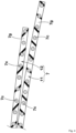
- FIG. 4 is an enlarged cross-sectional view of end portions of these belt plies.
- the belt plies include a plurality of belt cords 7c arranged at an angle of 15 to 45° relative to the tire circumferential direction, and a topping rubber 7g covering the belt cords 7c.
- the belt cords of the first belt ply 11 and the belt cords of the second belt ply 12 are inclined in directions opposite to each other with respect to the tire circumferential direction.
- the tread portion 2 is effectively reinforced.
- the plurality of belt cords 7c having a bending stiffness M (g cm) are arranged so as to have a number n of the belt cords 7c per ply width of 5 cm.
- the plurality of belt cords 7c having substantially the same flexural rigidity M are disposed in the first belt ply 11 and the second belt ply 12.
- the belt cords 7c are uniformly disposed in the first belt ply 11 and the second belt ply 12.
- the "bending stiffness M” is measured as follows. That is, the belt cord 7c is cut at a length of 70 mm so as not to be untwisted to take a test piece, and the test piece is measured by using, for example, a stiffness tester (Model 150-D) manufactured by TABER INDUSTRIES (USA), whereby the "bending stiffness M” is measured. Specifically, the “bending stiffness M” is obtained in a manner in which one end of the test piece is fixed, a force F is applied to the other end of the test piece extending from the fixed end over a length of 50 mm, and resistance (bending hardness) is measured when an opening angle becomes 15° at the other end of the test piece.
- the tread rubber 2G includes a cap rubber layer 15 forming a ground-contact surface 2s, and a base rubber layer 16 disposed inward of the cap rubber layer 15 in the tire radial direction.
- a complex elastic modulus E* 1 (MPa) of the cap rubber layer 15 is larger than a complex elastic modulus E*2 (MPa) of the base rubber layer 16.
- a complex elastic modulus is a value measured in accordance with the standards of JIS-K6394 under the following conditions using a viscoelasticity spectrometer.
- the complex elastic modulus E* 1 of the cap rubber layer 15, the complex elastic modulus E*2 of the base rubber layer 16, the bending stiffness M of the belt cords 7c, and the number n of the belt cords 7c satisfy a relationship of the following formula (1).
- the pneumatic tire of the present invention can improve wear resistance and ride comfort. The reason for this is as follows. M ⁇ n ⁇ E * 1 / E * 2 ⁇ 3000
- the inventor of the present invention has found that a product of the bending stiffness M and the number n of the belt cords 7c in the belt layer 7 is largely involved with the stiffness of the tread portion 2, and has a large influence on wear resistance and ride comfort.
- the inventor has found that the larger the ratio (E*1/E*2) of the complex elastic modulus of the cap rubber layer 15 to the complex elastic modulus of the base rubber layer 16 is, the more the vibration absorption characteristics of the tread portion 2 are improved and the greater the contribution to improvement of ride comfort is.
- the inventor has focused on the relationship between theses parameters, and has specified the relationship of the above-described formula (1) as a result of various experiments. In the case where this relationship is satisfied, the vibration absorption characteristics of the tread portion 2 are ensured sufficiently with respect to the holding force of the belt layer 7 on the tread portion 2, and wear resistance and ride comfort can be improved.
- the average for each parameter is preferably applied to the formula (1).
- the "average for each parameter" to be adopted is, for example, a value obtained by sectioning an object to be measured into a plurality of very small areas each having an appropriate size, measuring a corresponding parameter of each very small area, and dividing the total of the obtained parameters of the very small areas, by the number of the very small areas obtained by the sectioning.
- "M ⁇ n" at the left side of the formula (1) is preferably not less than 40% and more preferably not less than 50% of "(E*1/E*2) ⁇ 3000" at the right side of the formula (1), and preferably not more than 80% and more preferably not more than 70% of "(E*1/E*2) ⁇ 3000" at the right side of the formula (1).
- Each of the plurality of belt cords 7c (shown in FIG. 4 ) is preferably a steel cord.
- the bending stiffness M of the belt cord 7c is preferably not less than 100 g cm, more preferably not less than 120 g cm, and even more preferably not less than 130 g cm, and is preferably not more than 300 g ⁇ cm, more preferably not more than 200 g ⁇ cm, and even more preferably not more than 190 g ⁇ cm.
- the number n of the belt cords 7c per ply width of 5 cm of the belt ply is, for example, 10 to 30 and preferably 23 to 27.
- Each of the plurality of belt cords 7c has a tensile strength T (N).
- the tensile strength T is preferably not less than 1000 N and more preferably not less than 1300 N, and is preferably not more than 2000 N and more preferably not more than 1700 N.
- the "tensile strength T" is a maximum load required for breaking a test piece and is obtained by measurement at a tensile speed of 5 cm/min. in accordance with a tensile test of (6.4) Load at break and Elongation at break in "Testing methods for steel tire cords" of JIS G3510.
- the complex elastic modulus E* 1, the complex elastic modulus E*2, the tensile strength T, and the number n preferably satisfy a relationship of the following formula (2). In the case where this relationship is satisfied, ride comfort can be reliably improved.
- T ⁇ n at the left side of the formula (2) is preferably not less than 40% and more preferably not less than 50% of "(E*1/E*2) ⁇ 35000" at the right side of the formula (2), and is preferably not more than 80% and more preferably not more than 70% of "(E*1/E*2) ⁇ 35000" at the right side of the formula (2).
- the complex elastic modulus E*1 of the cap rubber layer 15 is preferably not less than 8.0 MPa and more preferably not less than 9.0 MPa, and is preferably not more than 15.0 MPa and more preferably not more than 12.0 MPa.
- the complex elastic modulus E*2 of the base rubber layer 16 is preferably not less than 4.0 MPa and more preferably not less than 4.5 MPa, and is preferably not more than 9.0 MPa and more preferably not more than 7.0 MPa. Thus, sufficient wear resistance is obtained.
- the complex elastic modulus E*1 of the cap rubber layer 15 is preferably 1.5 to 2.5 times and more preferably 1.8 to 2.2 times the complex elastic modulus E*2 of the base rubber layer 16. Thus, separation between the cap rubber layer 15 and the base rubber layer 16 is inhibited, while the above-described effect is exhibited.
- An average thickness t2 of the cap rubber layer 15 is preferably 70% to 95% of an average thickness t1 of the tread rubber 2G.
- An average thickness t3 of the base rubber layer 16 is preferably 5% to 30% of the average thickness t1 of the tread rubber 2G.
- the average thickness t1 of the tread rubber 2G corresponds to a value obtained by dividing a cross-sectional area of the tread rubber 2G in a region inward of the ground-contact surface 2s of the tread portion 2 in the tire radial direction, by the length, in the tire axial direction, of the region of the tread rubber 2G.
- the tread portion 2 includes at least one groove 17.
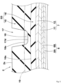
- FIG. 5 is an enlarged cross-sectional view of the groove 17 and the tread rubber 2G.
- the groove 17 provided in the tread portion 2 includes a groove bottom 17d, and a tread wear indicator 18 protruding locally from the groove bottom 17d.
- the tread wear indicator 18 is a small protrusion for indicating the limit of wear in the tread portion 2 and, for example, has a height of 1.6 mm.
- the tread wear indicator 18 in FIG. 5 is dotted. In FIG. 1 and FIG. 3 , the tread wear indicator 18 is omitted.
- an outer surface 16s, in the tire radial direction, of the base rubber layer 16 is located tire-radially inward of an outer surface 18s, in the tire radial direction, of the tread wear indicator 18. More specifically, the entire outer surface 16s of the base rubber layer 16 is located inward, in the tire radial direction, of a virtual line 19 extending along the ground-contact surface 2s of the tread portion 2 so as to pass through the outer surface 18s of the tread wear indicator 18.
- the cap rubber layer 15 is allowed to form an outer surface of the tread portion 2 until the end of the wear of the tread portion 2, and thus excellent wear resistance is exhibited over a long time.
- Pneumatic tires having a size of 205/40R15 and having the basic structure shown in FIG. 1 were produced as test tires based on the specifications indicated in Table 1.
- a tire that did not satisfy the above-described formula (1) was produced as a test tire.
- the tire of the comparative example had substantially the same structure as the tires of the examples except for the above-described matter. Ride comfort and wear resistance were tested for each test tire.
- the common specifications and the test methods for the test tires are as follows.
- a driver drove the above-described test vehicle having the test tires mounted thereon, and, at that time, sensory evaluation was made by the driver in terms of ride comfort.
- the results are indicated as scores with the ride comfort of the comparative example being 100. The greater the value is, the more excellent ride comfort is.
- the present invention includes the following aspects.
- a pneumatic tire to be mounted and used on a rim in which
- the pneumatic tire according to Present Invention 2 in which the tensile strength T is 1000 to 2000 N.
- each of the plurality of belt cords is a steel cord.
- the pneumatic tire according to Present Invention 8 in which the bending stiffness M is 100 to 300 g ⁇ cm.
Landscapes
- Engineering & Computer Science (AREA)
- Mechanical Engineering (AREA)
- Tires In General (AREA)
Abstract

Description
- The present invention relates to a pneumatic tire.
- In recent years, various kinds of small-size buses intended to transport people or articles in urban areas have been proposed (e.g., see
Japanese Laid-Open Patent Publication No. 2021-075088 - A tire mounted to the above-described small-size bus is required to have a reduced outer diameter in order to maximize a vehicle cabin space. On the other hand, since this type of tire receives a high load, excellent wear resistance is required. Further, from the viewpoint of increasing the comfort of the occupant, the tire is also required to provide excellent ride comfort.
- The present invention has been made in view of the above circumstances, and a main object of the present invention is to provide a pneumatic tire which has a specific tire size and has improved wear resistance and ride comfort.
- The present invention is directed to a pneumatic tire to be mounted and used on a rim. The rim has a rim diameter RD of 12 to 17 inches. A ratio SH/SW of a tire cross-sectional height SH to a tire cross-sectional width SW is 0.30 to 0.45. A ratio RW/SW of a rim width RW of the rim to the tire cross-sectional width SW is 0.78 to 0.99. The pneumatic tire includes a tread portion. The tread portion includes a tread rubber, and a belt layer including two belt plies and disposed inward of the tread rubber in a tire radial direction. The tread rubber includes a cap rubber layer forming a ground-contact surface, and a base rubber layer disposed inward of the cap rubber layer in the tire radial direction. A complex elastic modulus E* 1 (MPa) of the cap rubber layer is larger than a complex elastic modulus E*2 (MPa) of the base rubber layer. In the belt plies, a plurality of belt cords having a flexural rigidity M (g cm) are arranged so as to have a number n of the belt cords per ply width of 5 cm. The complex elastic modulus E* 1, the complex elastic modulus E*2, the flexural rigidity M, and the number n satisfy a relationship of a following formula (1).

- The pneumatic tire of the present invention has the above-described structure, and thus can improve wear resistance and ride comfort.
-
-
FIG. 1 is a transverse cross-sectional view of a pneumatic tire according to one embodiment of the present invention; -
FIG. 2 is a perspective view of a vehicle on which the tires of the present invention are mounted; -
FIG. 3 is an enlarged cross-sectional view of a tread portion inFIG. 1 ; -
FIG. 4 is an enlarged cross-sectional view of end portions of belt plies inFIG. 3 ; and -
FIG. 5 is an enlarged cross-sectional view of a groove and a tread rubber inFIG. 3 . - Hereinafter, an embodiment of the present invention will be described with reference to the drawings. The drawings connote the characteristics of the present invention, but may contain exaggerated expressions and expressions that differ from the dimensional ratio of the actual structure in order to help the understanding of the present invention. In addition, the same or common elements are denoted by the same reference characters throughout each embodiment, and the redundant description thereof is omitted. A known configuration can be used as appropriate for a configuration that is not described in the present description.
-
FIG. 1 is a transverse cross-sectional view of a pneumatic tire 1 (hereinafter, may be simply referred to as "tire 1") according to one embodiment of the present invention.FIG. 2 is a perspective view conceptually showing a vehicle Ve on which the tires 1 of the present invention are mounted. As shown inFIG. 1 andFIG. 2 , the tire 1 of the present embodiment is mounted and used on a rim R, and is suitably used as a pneumatic tire for the vehicle Ve such as a small-size bus or a small-size shuttle bus, for example. - As shown in
FIG. 2 , the above-described vehicle Ve is a four-wheel automobile. The vehicle Ve is not limited to a four-wheel one, and may have six wheels or eight wheels. In addition, a predetermined number of the tires 1 are mounted to the vehicle Ve according to the wheel structure. - The vehicle Ve falls under a small-size shuttle bus to be used for transporting people or articles in urban areas, for example. As the small-size shuttle bus, a vehicle having an entire length of 4 m to 7 m, an entire width of about 2 m, and a total vehicle weight of about 3 t is assumed. However, the tire 1 of the present invention may be used for not only the vehicles in the above-described range but also various kinds of vehicles.
- The vehicle Ve may be used not only for transportation of people but also for transportation of articles, and may be further used as a mobile store, a mobile office, or the like. The vehicle Ve is preferably an electric automobile having an automatic driving function, for example. In addition, the vehicle Ve is mainly intended for transporting people, articles, and the like in urban areas, and thus is assumed to have a relatively low running speed range (an average speed of about 50 km/h). Thus, importance need not necessarily be placed on wet performance. However, the vehicle Ve is not limited to such a mode.
- In the case where the vehicle Ve is an electric automobile, a motor is preferably disposed in a rim. In this case, the vehicle Ve preferably has an independent steering function that allows each wheel to be steered independently. Accordingly, turning or the like is easily performed on the spot, and a vehicle cabin space of the vehicle Ve can be increased.
- The tire 1 of the present embodiment to be used for such a vehicle Ve is required to have a high space efficiency. Thus, a rim diameter for the tire 1 is required to be small, or the tire 1 is required to have a small tire cross-sectional height. Meanwhile, the vehicle Ve has a commensurate weight, and thus the tire 1 is also required to have high wear resistance. In addition, the vehicle Ve is also required to provide excellent ride comfort.
-
FIG. 1 is a transverse cross-sectional view, including a tire rotation axis, of the tire 1 in a standardized state. In the case of a pneumatic tire for which various standards are defined, the "standardized state" refers to a state in which a tire is mounted on a standardized rim and is inflated to a standardized internal pressure and no load is applied to the tire. In the case of a tire for which various standards are not defined, the standardized state means a standard use state, corresponding to the purpose of use of the tire, in which the tire is not mounted on a vehicle and no load is applied to the tire. In the present description, unless otherwise specified, dimensions and the like of components of the tire are values measured in the standardized state. In addition, dimensions of components (e.g., an inner member of the tire 1) that cannot be measured in the standardized state are values measured in a state in which the tire 1 is made to approximate the standardized state as much as possible. - The "standardized rim" refers to a rim that is defined, in a standard system including a standard on which the tire is based, by the standard for each tire, and is, for example, "standard rim" in the JATMA standard, "Design Rim" in the TRA standard, or "Measuring Rim" in the ETRTO standard.
- The "standardized internal pressure" refers to an air pressure that is defined, in a standard system including a standard on which the tire is based, by the standard for each tire, and is "maximum air pressure" in the JATMA standard, the maximum value recited in the table "TIRE LOAD LIMITS AT VARIOUS COLD INFLATION PRESSURES" in the TRA standard, or "INFLATION PRESSURE" in the ETRTO standard.
- The tire 1 includes a
tread portion 2, a pair ofsidewall portions 3, and a pair ofbead portions 4. Thesidewall portions 3 are respectively connected to the outer sides of thetread portion 2 in a tire axial direction, and extend in a tire radial direction. Thebead portions 4 are respectively connected to the inner sides of thesidewall portions 3 in the tire radial direction. In addition, the tire 1 includes acarcass 6. Thecarcass 6 extends between the pair ofbead portions 4. In other words, thecarcass 6 extends from one of thebead portions 4 to the other of thebead portions 4, through one of thesidewall portions 3, thetread portion 2, and the other of thesidewall portions 3. - The
carcass 6 includes two carcass plies 6A, 6B, for example. Each carcass ply includes abody portion 6a and turned-upportions 6b, for example. Thebody portion 6a extends between the pair ofbead portions 4, for example. The turned-upportions 6b are connected to thebody portion 6a, and are respectively turned up aroundbead cores 5 from the inner side to the outer side in the tire axial direction. - The carcass plies 6A, 6B each include a plurality of carcass cords and a topping rubber covering the carcass cords (not shown). As the carcass cords, for example, organic fiber cords such as aramid cords and rayon cords are used. The carcass cords are preferably arranged at an angle of 70 to 90° relative to a tire equator C, for example. However, the tire 1 of the present invention is not limited to such a mode.
- In the present invention, the rim R has a rim diameter RD of 12 to 17 inches. In addition, a ratio SH/SW of a tire cross-sectional height SH to a cross-sectional width SW of the tire 1 is 0.30 to 0.45. A ratio RW/SW of a rim width RW of the rim R to the cross-sectional width SW of the tire 1 is 0.78 to 0.99. The cross-sectional width SW is, for example, 150 to 250 mm.
- The rim diameter RD is an outer diameter of a rim body part to which the
bead cores 5 of thebead portions 4 fit. In addition, when projections (not shown) representing patterns or characters are provided on the side walls of the tire 1, the cross-sectional width SW of the tire 1 corresponds to a width obtained by excluding the projections. The cross-sectional height SH of the tire 1 corresponds to 1/2 of the difference between an outer diameter of the tire and the rim diameter RD. In other words, the cross-sectional height SH corresponds to a distance in the tire radial direction from a bead base line BL to an outer end, in the tire radial direction, of the tire 1. The bead base line BL means a tire axial line passing through a rim diameter position. - The rim width RW of the rim R corresponds to a distance in the tire axial direction from an inner surface of one of rim flanges Rf to an inner surface of the other of the rim flanges Rf. In the case where the inner surfaces are inclined, the above-described distance is measured at the center position, in the tire radial direction, of each
bead core 5 of the tire 1 mounted on the rim R. - As described above, in the tire 1 of the present invention, the rim diameter RD and the cross-sectional height SH are relatively small, and the rim width RW is relatively large with respect to the tire cross-sectional width SW. For example, such a tire 1 mounted on the above-described vehicle Ve (shown in
FIG. 2 ) allows space efficiency to be enhanced in a vehicle space, and allows, in a vehicle having a motor disposed inside the rim, a sufficient storage space for the motor to be ensured. In addition, such a tire 1 can retain a sufficient air volume for supporting the total weight of the vehicle. -
FIG. 3 is an enlarged cross-sectional view of thetread portion 2 of the tire 1 inFIG. 1 . As shown inFIG. 3 , thetread portion 2 includes atread rubber 2G, and abelt layer 7 including two belt plies and disposed inward of thetread rubber 2G in the tire radial direction. - The
belt layer 7 of the present embodiment includes a first belt ply 11 adjacent to thecarcass 6, and a second belt ply 12 disposed outward of the first belt ply 11 in the tire radial direction.FIG. 4 is an enlarged cross-sectional view of end portions of these belt plies. As shown inFIG. 4 , the belt plies include a plurality ofbelt cords 7c arranged at an angle of 15 to 45° relative to the tire circumferential direction, and a toppingrubber 7g covering thebelt cords 7c. The belt cords of thefirst belt ply 11 and the belt cords of the second belt ply 12 are inclined in directions opposite to each other with respect to the tire circumferential direction. Thus, thetread portion 2 is effectively reinforced. - In the
first belt ply 11 and thesecond belt ply 12, the plurality ofbelt cords 7c having a bending stiffness M (g cm) are arranged so as to have a number n of thebelt cords 7c per ply width of 5 cm. In a preferable mode, in the present embodiment, the plurality ofbelt cords 7c having substantially the same flexural rigidity M are disposed in thefirst belt ply 11 and thesecond belt ply 12. In addition, thebelt cords 7c are uniformly disposed in thefirst belt ply 11 and thesecond belt ply 12. - The "bending stiffness M" is measured as follows. That is, the
belt cord 7c is cut at a length of 70 mm so as not to be untwisted to take a test piece, and the test piece is measured by using, for example, a stiffness tester (Model 150-D) manufactured by TABER INDUSTRIES (USA), whereby the "bending stiffness M" is measured. Specifically, the "bending stiffness M" is obtained in a manner in which one end of the test piece is fixed, a force F is applied to the other end of the test piece extending from the fixed end over a length of 50 mm, and resistance (bending hardness) is measured when an opening angle becomes 15° at the other end of the test piece. - As shown in
FIG. 3 , thetread rubber 2G includes acap rubber layer 15 forming a ground-contact surface 2s, and abase rubber layer 16 disposed inward of thecap rubber layer 15 in the tire radial direction. In the present invention, a complex elastic modulus E* 1 (MPa) of thecap rubber layer 15 is larger than a complex elastic modulus E*2 (MPa) of thebase rubber layer 16. In the present description, a complex elastic modulus is a value measured in accordance with the standards of JIS-K6394 under the following conditions using a viscoelasticity spectrometer. - Initial strain: 10%
- Amplitude: ±2%
- Frequency: 10 Hz
- Deformation mode: tension
- Measurement temperature: 30°C
- In the pneumatic tire 1 of the present invention, the complex elastic modulus E* 1 of the
cap rubber layer 15, the complex elastic modulus E*2 of thebase rubber layer 16, the bending stiffness M of thebelt cords 7c, and the number n of thebelt cords 7c satisfy a relationship of the following formula (1). Thus, the pneumatic tire of the present invention can improve wear resistance and ride comfort. The reason for this is as follows.
- The inventor of the present invention has found that a product of the bending stiffness M and the number n of the
belt cords 7c in thebelt layer 7 is largely involved with the stiffness of thetread portion 2, and has a large influence on wear resistance and ride comfort. In addition, the inventor has found that the larger the ratio (E*1/E*2) of the complex elastic modulus of thecap rubber layer 15 to the complex elastic modulus of thebase rubber layer 16 is, the more the vibration absorption characteristics of thetread portion 2 are improved and the greater the contribution to improvement of ride comfort is. Further, the inventor has focused on the relationship between theses parameters, and has specified the relationship of the above-described formula (1) as a result of various experiments. In the case where this relationship is satisfied, the vibration absorption characteristics of thetread portion 2 are ensured sufficiently with respect to the holding force of thebelt layer 7 on thetread portion 2, and wear resistance and ride comfort can be improved. - In the present invention, from the viewpoint of allowing for the variation of each of the above-described parameters (the complex elastic modulus E*1, the complex elastic modulus E*2, the bending stiffness M, and the number n), the average for each parameter is preferably applied to the formula (1). The "average for each parameter" to be adopted is, for example, a value obtained by sectioning an object to be measured into a plurality of very small areas each having an appropriate size, measuring a corresponding parameter of each very small area, and dividing the total of the obtained parameters of the very small areas, by the number of the very small areas obtained by the sectioning.
- Hereinafter, more detailed configurations of the present embodiment will be described. The configurations described below show a specific mode of the present embodiment. Therefore, it is needless to say that the present invention can achieve the above-described effect even when the configurations described below are not provided. In addition, even when any one of the configurations described below is independently applied to the tire according to the present invention having the above-described characteristics, performance improvement corresponding to each configuration can be expected. Furthermore, when some of the configurations described below are applied in combination, complex performance improvement corresponding to each configuration can be expected.
- From the viewpoint of improving wear resistance and ride comfort in a well-balanced manner, "M×n" at the left side of the formula (1) is preferably not less than 40% and more preferably not less than 50% of "(E*1/E*2)×3000" at the right side of the formula (1), and preferably not more than 80% and more preferably not more than 70% of "(E*1/E*2)×3000" at the right side of the formula (1).
- Each of the plurality of
belt cords 7c (shown inFIG. 4 ) is preferably a steel cord. In addition, the bending stiffness M of thebelt cord 7c is preferably not less than 100 g cm, more preferably not less than 120 g cm, and even more preferably not less than 130 g cm, and is preferably not more than 300 g·cm, more preferably not more than 200 g·cm, and even more preferably not more than 190 g·cm. Thus, wear resistance and ride comfort are improved in a well-balanced manner. - The number n of the
belt cords 7c per ply width of 5 cm of the belt ply is, for example, 10 to 30 and preferably 23 to 27. - Each of the plurality of
belt cords 7c has a tensile strength T (N). The tensile strength T is preferably not less than 1000 N and more preferably not less than 1300 N, and is preferably not more than 2000 N and more preferably not more than 1700 N. Thus, wear resistance and ride comfort are improved in a well-balanced manner. The "tensile strength T" is a maximum load required for breaking a test piece and is obtained by measurement at a tensile speed of 5 cm/min. in accordance with a tensile test of (6.4) Load at break and Elongation at break in "Testing methods for steel tire cords" of JIS G3510. - In a more preferable mode, the complex elastic modulus E* 1, the complex elastic modulus E*2, the tensile strength T, and the number n preferably satisfy a relationship of the following formula (2). In the case where this relationship is satisfied, ride comfort can be reliably improved.

- From the viewpoint of improving wear resistance and ride comfort in a well-balanced manner, "T×n" at the left side of the formula (2) is preferably not less than 40% and more preferably not less than 50% of "(E*1/E*2)×35000" at the right side of the formula (2), and is preferably not more than 80% and more preferably not more than 70% of "(E*1/E*2)×35000" at the right side of the formula (2).
- The complex elastic modulus E*1 of the
cap rubber layer 15 is preferably not less than 8.0 MPa and more preferably not less than 9.0 MPa, and is preferably not more than 15.0 MPa and more preferably not more than 12.0 MPa. In addition, the complex elastic modulus E*2 of thebase rubber layer 16 is preferably not less than 4.0 MPa and more preferably not less than 4.5 MPa, and is preferably not more than 9.0 MPa and more preferably not more than 7.0 MPa. Thus, sufficient wear resistance is obtained. - The complex elastic modulus E*1 of the
cap rubber layer 15 is preferably 1.5 to 2.5 times and more preferably 1.8 to 2.2 times the complex elastic modulus E*2 of thebase rubber layer 16. Thus, separation between thecap rubber layer 15 and thebase rubber layer 16 is inhibited, while the above-described effect is exhibited. - An average thickness t2 of the
cap rubber layer 15 is preferably 70% to 95% of an average thickness t1 of thetread rubber 2G. An average thickness t3 of thebase rubber layer 16 is preferably 5% to 30% of the average thickness t1 of thetread rubber 2G. Thus, wear resistance and ride comfort are improved in a well-balanced manner. The average thickness t1 of thetread rubber 2G corresponds to a value obtained by dividing a cross-sectional area of thetread rubber 2G in a region inward of the ground-contact surface 2s of thetread portion 2 in the tire radial direction, by the length, in the tire axial direction, of the region of thetread rubber 2G. The same applies to the average thickness t2 of thecap rubber layer 15 and the average thickness t3 of thebase rubber layer 16. - The
tread portion 2 includes at least onegroove 17.FIG. 5 is an enlarged cross-sectional view of thegroove 17 and thetread rubber 2G. As shown inFIG. 5 , thegroove 17 provided in thetread portion 2 includes agroove bottom 17d, and atread wear indicator 18 protruding locally from thegroove bottom 17d. The tread wearindicator 18 is a small protrusion for indicating the limit of wear in thetread portion 2 and, for example, has a height of 1.6 mm. For easy understanding, the tread wearindicator 18 inFIG. 5 is dotted. InFIG. 1 andFIG. 3 , the tread wearindicator 18 is omitted. - In a preferable mode, an
outer surface 16s, in the tire radial direction, of thebase rubber layer 16 is located tire-radially inward of anouter surface 18s, in the tire radial direction, of the tread wearindicator 18. More specifically, the entireouter surface 16s of thebase rubber layer 16 is located inward, in the tire radial direction, of avirtual line 19 extending along the ground-contact surface 2s of thetread portion 2 so as to pass through theouter surface 18s of the tread wearindicator 18. Thus, thecap rubber layer 15 is allowed to form an outer surface of thetread portion 2 until the end of the wear of thetread portion 2, and thus excellent wear resistance is exhibited over a long time. - Although the pneumatic tire according to the embodiment of the present invention has been described above in detail, the present invention is not limited to the above specific embodiment, and various modifications can be made to implement the present invention.
- Pneumatic tires having a size of 205/40R15 and having the basic structure shown in
FIG. 1 were produced as test tires based on the specifications indicated in Table 1. In addition, as a comparative example, a tire that did not satisfy the above-described formula (1) was produced as a test tire. The tire of the comparative example had substantially the same structure as the tires of the examples except for the above-described matter. Ride comfort and wear resistance were tested for each test tire. The common specifications and the test methods for the test tires are as follows. - Rim on which the tire was mounted: 15×7.0J
- Tire internal pressure: 520 kPa
- Test vehicle: e-Pallet manufactured by TOYOTA MOTOR CORPORATION
- A driver drove the above-described test vehicle having the test tires mounted thereon, and, at that time, sensory evaluation was made by the driver in terms of ride comfort. The results are indicated as scores with the ride comfort of the comparative example being 100. The greater the value is, the more excellent ride comfort is.
- Wear energy was measured when running with each test tire was performed on a GPS testing machine. The results were indicated as indexes with the reciprocal of the wear energy of the comparative example being 100. The greater the value is, the smaller wear energy is and the more excellent wear resistance is.
- Table 1 indicates the test results.
[Table 1] Comp. Ex. Ex. 1 Ex. 2 Ex. 3 Ex. 4 Ex. 5 Ex. 6 Ex. 7 Complex elastic modulus E* 1 (MPa) of cap rubber layer 9.7 9.7 8.0 10.0 10.0 10.0 10.0 10.0 Complex elastic modulus E*2 (MPa) of base rubber layer 8.26 4.63 4.63 4.63 4.63 4.63 4.63 4.63 Flexural rigidity M (g•cm) of belt cord 149 149 149 100 149 149 149 151 Number n of belt cords 25.7 25.7 25.7 25.7 25.7 25.7 25.7 19.8 Tensile strength T (N) of belt cord 1650 1650 1650 1650 1650 1000 2000 1650 A=(E*1/E*2)×3000 3523 6285 5184 6479 6479 7127 7127 6479 B=(E*1/E*2)×35000 41102 73326 60475 75594 75594 83153 83153 75594 C=M×n 3829 3829 3829 2570 3829 3395 4644 2990 D=T×n 42405 42405 42405 42405 42405 36237 42405 32670 Ratio C/A 1.09 0.61 0.74 0.40 0.59 0.48 0.65 0.46 Ratio D/B 1.03 0.58 0.70 0.56 0.56 0.44 0.51 0.43 Ride comfort (score) 100 106 105 109 106 109 105 109 Wear resistance (index) 100 105 104 105 104 105 105 105 [Table 2] Ex. 8 Ex. 9 Ex. 10 Ex. 11 Ex. 12 Ex. 13 Ex. 14 Complex elastic modulus E* 1 (MPa) of cap rubber layer 11.0 11.0 11.0 11.0 15.0 10.0 10.6 Complex elastic modulus E*2 (MPa) of base rubber layer 4.63 4.63 4.63 4.63 4.63 6 8.26 Bending stiffness M (g·cm) of belt cord 132 151 181 300 149 149 149 Number n of belt cords 26 25.7 26 23.0 25.7 25.7 25.7 Tensile strength T (N) of belt cord 1410 1410 1650 1650 1650 1650 1650 A=(E*1/E*2)×3000 7127 7127 7127 7127 9719 5000 3850 B=(E*1/E*2)×35000 83153 83153 83153 83153 113391 58333 44915 C=M×n 3395 3881 4644 6900 3829 3829 3829 D=T×n 36237 36237 42405 37950 42405 42405 42405 Ratio C/A 0.48 0.54 0.65 0.97 0.39 0.77 0.99 Ratio D/B 0.44 0.44 0.51 0.46 0.37 0.73 0.94 Ride comfort (score) 109 108 106 102 110 104 101 Wear resistance (index) 106 106 106 106 107 103 102 - If the ratio C/A shown in Tables 1 and 2 is smaller than 1, a relationship of the above-described formula (1) is satisfied. In addition, if the ratio D/B shown in Tables 1 and 2 is smaller than 1, a relationship of the above-described formula (2) is satisfied. As shown in Tables 1 and 2, the tire of each example has significantly improved wear resistance and ride comfort. That is, in the present invention, it is confirmed that the specific tire size allows improvement of wear resistance and ride comfort.
- The present invention includes the following aspects.
- A pneumatic tire to be mounted and used on a rim, in which
- the rim has a rim diameter RD of 12 to 17 inches,
- a ratio SH/SW of a tire cross-sectional height SH to a tire cross-sectional width SW is 0.30 to 0.45,
- a ratio RW/SW of a rim width RW of the rim to the tire cross-sectional width SW is 0.78 to 0.99,
- the pneumatic tire includes a tread portion,
- the tread portion includes a tread rubber, and a belt layer including two belt plies and disposed inward of the tread rubber in a tire radial direction,
- the tread rubber includes a cap rubber layer forming a ground-contact surface, and a base rubber layer disposed inward of the cap rubber layer in the tire radial direction,
- a complex elastic modulus E* 1 (MPa) of the cap rubber layer is larger than a complex elastic modulus E*2 (MPa) of the base rubber layer,
- in the belt plies, a plurality of belt cords having a bending stiffness M (g cm) are arranged so as to have a number n of the belt cords per ply width of 5 cm, and
- the complex elastic modulus E* 1, the complex elastic modulus E*2, the bending stiffness M, and the number n satisfy a relationship of a following formula (1).

- The pneumatic tire according to Present Invention 1, in which
- each of the plurality of belt cords has a tensile strength T (N), and
- the complex elastic modulus E* 1, the complex elastic modulus E*2, the tensile strength T, and the number n satisfy a relationship of a following formula (2).

- The pneumatic tire according to
Present Invention 2, in which the tensile strength T is 1000 to 2000 N. - The pneumatic tire according to any one of Present Inventions 1 to 3, in which an average thickness of the base rubber layer is 5% to 30% of an average thickness of the tread rubber.
- The pneumatic tire according to any one of Present Inventions 1 to 3, in which
- the tread portion includes at least one groove,
- the groove includes a groove bottom, and a tread wear indicator protruding locally from the groove bottom, and
- an outer surface, in the tire radial direction, of the base rubber layer is located inward of an outer surface, in the tire radial direction, of the tread wear indicator in the tire radial direction.
- The pneumatic tire according to any one of Present Inventions 1 to 3, in which the complex elastic modulus E*1 is 8.0 to 15.0 MPa.
- The pneumatic tire according to any one of Present Inventions 1 to 3, in which the complex elastic modulus E*2 is 4.0 to 9.0 MPa.
- The pneumatic tire according to any one of Present Inventions 1 to 3, in which each of the plurality of belt cords is a steel cord.
- The pneumatic tire according to Present Invention 8, in which the bending stiffness M is 100 to 300 g·cm.
Claims (9)
- A pneumatic tire (1) to be mounted and used on a rim (R), whereinthe rim (R) has a rim diameter (RD) of 12 to 17 inches,a ratio (SH/SW) of a tire cross-sectional height (SH) to a tire cross-sectional width (SW) is 0.30 to 0.45,a ratio (RW/SW) of a rim width (RW) of the rim (R) to the tire cross-sectional width (SW) is 0.78 to 0.99,the pneumatic tire (1) includes a tread portion (2),the tread portion (2) includes a tread rubber (2G), and a belt layer (7) including two belt plies (11, 12) and disposed inward of the tread rubber (2G) in a tire radial direction,the tread rubber (2G) includes a cap rubber layer (15) forming a ground-contact surface (2s), and a base rubber layer (16) disposed inward of the cap rubber layer (15) in the tire radial direction,a complex elastic modulus (E*1) (MPa) of the cap rubber layer (15) is larger than a complex elastic modulus (E*2) (MPa) of the base rubber layer (16),in the belt plies (11, 12), a plurality of belt cords (7c) having a bending stiffness (M) (g cm) are arranged so as to have a number (n) of the belt cords (7c) per ply width of 5 cm, andthe complex elastic modulus (E*1), the complex elastic modulus (E*2), the bending stiffness (M), and the number (n) satisfy a relationship of a following formula (1).

- The pneumatic tire (1) according to claim 1, whereineach of the plurality of belt cords (7c) has a tensile strength (T) (N), andthe complex elastic modulus (E*1), the complex elastic modulus (E*2), the tensile strength (T), and the number (n) satisfy a relationship of a following formula (2).

- The pneumatic tire (1) according to claim 2, wherein the tensile strength (T) is 1000 to 2000 N.
- The pneumatic tire (1) according to any one of claims 1 to 3, wherein an average thickness (t3) of the base rubber layer (16) is 5% to 30% of an average thickness (t1) of the tread rubber (2G).
- The pneumatic tire (1) according to any one of claims 1 to 4, whereinthe tread portion (2) includes at least one groove (17),the groove (17) includes a groove bottom (17d), and a tread wear indicator (18) protruding locally from the groove bottom (17d), andan outer surface (16s), in the tire radial direction, of the base rubber layer (16) is located inward of an outer surface (18s), in the tire radial direction, of the tread wear indicator (18) in the tire radial direction.
- The pneumatic tire (1) according to any one of claims 1 to 5, wherein the complex elastic modulus (E* 1) is 8.0 to 15.0 MPa.
- The pneumatic tire (1) according to any one of claims 1 to 6, wherein the complex elastic modulus (E*2) is 4.0 to 9.0 MPa.
- The pneumatic tire (1) according to any one of claims 1 to 7, wherein each of the plurality of belt cords (7c) is a steel cord.
- The pneumatic tire (1) according to claim 8, wherein the bending stiffness (M) is 100 to 300 g·cm.
Applications Claiming Priority (1)
| Application Number | Priority Date | Filing Date | Title |
|---|---|---|---|
| JP2023102255A JP2025002223A (en) | 2023-06-22 | 2023-06-22 | Pneumatic tire |
Publications (2)
| Publication Number | Publication Date |
|---|---|
| EP4480715A1 true EP4480715A1 (en) | 2024-12-25 |
| EP4480715B1 EP4480715B1 (en) | 2025-12-17 |
Family
ID=90922582
Family Applications (1)
| Application Number | Title | Priority Date | Filing Date |
|---|---|---|---|
| EP24172609.0A Active EP4480715B1 (en) | 2023-06-22 | 2024-04-26 | Pneumatic tire |
Country Status (2)
| Country | Link |
|---|---|
| EP (1) | EP4480715B1 (en) |
| JP (1) | JP2025002223A (en) |
Cited By (1)
| Publication number | Priority date | Publication date | Assignee | Title |
|---|---|---|---|---|
| EP4585429A1 (en) * | 2024-01-09 | 2025-07-16 | Sumitomo Rubber Industries, Ltd. | Pneumatic tire |
Citations (5)
| Publication number | Priority date | Publication date | Assignee | Title |
|---|---|---|---|---|
| JPH0399903A (en) * | 1989-09-14 | 1991-04-25 | Sumitomo Rubber Ind Ltd | Radial tire for heavy load |
| EP3348423A1 (en) * | 2015-09-07 | 2018-07-18 | Bridgestone Corporation | Pneumatic tire |
| JP2021075088A (en) | 2019-11-05 | 2021-05-20 | トヨタ自動車株式会社 | Vehicle frame structure |
| EP3882049A1 (en) * | 2018-12-13 | 2021-09-22 | Bridgestone Corporation | Pneumatic tire |
| US20230373250A1 (en) * | 2020-10-09 | 2023-11-23 | Compagnie Generale Des Etablissements Michelin | Mounted assembly including a pneumatic tire |
-
2023
- 2023-06-22 JP JP2023102255A patent/JP2025002223A/en active Pending
-
2024
- 2024-04-26 EP EP24172609.0A patent/EP4480715B1/en active Active
Patent Citations (5)
| Publication number | Priority date | Publication date | Assignee | Title |
|---|---|---|---|---|
| JPH0399903A (en) * | 1989-09-14 | 1991-04-25 | Sumitomo Rubber Ind Ltd | Radial tire for heavy load |
| EP3348423A1 (en) * | 2015-09-07 | 2018-07-18 | Bridgestone Corporation | Pneumatic tire |
| EP3882049A1 (en) * | 2018-12-13 | 2021-09-22 | Bridgestone Corporation | Pneumatic tire |
| JP2021075088A (en) | 2019-11-05 | 2021-05-20 | トヨタ自動車株式会社 | Vehicle frame structure |
| US20230373250A1 (en) * | 2020-10-09 | 2023-11-23 | Compagnie Generale Des Etablissements Michelin | Mounted assembly including a pneumatic tire |
Cited By (1)
| Publication number | Priority date | Publication date | Assignee | Title |
|---|---|---|---|---|
| EP4585429A1 (en) * | 2024-01-09 | 2025-07-16 | Sumitomo Rubber Industries, Ltd. | Pneumatic tire |
Also Published As
| Publication number | Publication date |
|---|---|
| JP2025002223A (en) | 2025-01-09 |
| EP4480715B1 (en) | 2025-12-17 |
Similar Documents
| Publication | Publication Date | Title |
|---|---|---|
| US9150051B2 (en) | Pneumatic tire | |
| US20040238094A1 (en) | Pneumatic radial tire | |
| US20200324583A1 (en) | Run-Flat Tire | |
| EP2206612B1 (en) | Tire for motor-bicycle | |
| EP2735455B1 (en) | Run-flat tire and mounting method thereof | |
| US10328753B2 (en) | Pneumatic tire | |
| US10870318B2 (en) | Pneumatic tire | |
| US11338622B2 (en) | Run-flat tire | |
| EP4124471B1 (en) | Tire | |
| US10596860B2 (en) | Pneumatic tire | |
| US8944124B2 (en) | Pneumatic tire for a motorcycle | |
| KR101914816B1 (en) | Run-flat tire | |
| EP4480715B1 (en) | Pneumatic tire | |
| EP3936352B1 (en) | Pneumatic tire | |
| EP3936660B1 (en) | Tire | |
| EP4201703B1 (en) | Tire | |
| EP4173844B1 (en) | Pneumatic tire | |
| JP6790547B2 (en) | Pneumatic tires | |
| EP3943660B1 (en) | Tire | |
| JP4653556B2 (en) | Run-flat tire and vehicle using the same | |
| US20230339267A1 (en) | Pneumatic tire | |
| EP4385758B1 (en) | Pneumatic tire | |
| EP4585429B1 (en) | Pneumatic tire | |
| JP2022147003A (en) | tire | |
| EP4592092A1 (en) | Pneumatic tire |
Legal Events
| Date | Code | Title | Description |
|---|---|---|---|
| PUAI | Public reference made under article 153(3) epc to a published international application that has entered the european phase |
Free format text: ORIGINAL CODE: 0009012 |
|
| STAA | Information on the status of an ep patent application or granted ep patent |
Free format text: STATUS: THE APPLICATION HAS BEEN PUBLISHED |
|
| AK | Designated contracting states |
Kind code of ref document: A1 Designated state(s): AL AT BE BG CH CY CZ DE DK EE ES FI FR GB GR HR HU IE IS IT LI LT LU LV MC ME MK MT NL NO PL PT RO RS SE SI SK SM TR |
|
| P01 | Opt-out of the competence of the unified patent court (upc) registered |
Free format text: CASE NUMBER: APP_12440/2025 Effective date: 20250313 |
|
| STAA | Information on the status of an ep patent application or granted ep patent |
Free format text: STATUS: REQUEST FOR EXAMINATION WAS MADE |
|
| 17P | Request for examination filed |
Effective date: 20250530 |
|
| GRAP | Despatch of communication of intention to grant a patent |
Free format text: ORIGINAL CODE: EPIDOSNIGR1 |
|
| STAA | Information on the status of an ep patent application or granted ep patent |
Free format text: STATUS: GRANT OF PATENT IS INTENDED |
|
| INTG | Intention to grant announced |
Effective date: 20250925 |
|
| GRAS | Grant fee paid |
Free format text: ORIGINAL CODE: EPIDOSNIGR3 |
|
| GRAA | (expected) grant |
Free format text: ORIGINAL CODE: 0009210 |
|
| STAA | Information on the status of an ep patent application or granted ep patent |
Free format text: STATUS: THE PATENT HAS BEEN GRANTED |
|
| AK | Designated contracting states |
Kind code of ref document: B1 Designated state(s): AL AT BE BG CH CY CZ DE DK EE ES FI FR GB GR HR HU IE IS IT LI LT LU LV MC ME MK MT NL NO PL PT RO RS SE SI SK SM TR |
|
| REG | Reference to a national code |
Ref country code: CH Ref legal event code: F10 Free format text: ST27 STATUS EVENT CODE: U-0-0-F10-F00 (AS PROVIDED BY THE NATIONAL OFFICE) Effective date: 20251217 Ref country code: GB Ref legal event code: FG4D |
|
| REG | Reference to a national code |
Ref country code: DE Ref legal event code: R096 Ref document number: 602024001698 Country of ref document: DE |
|
| REG | Reference to a national code |
Ref country code: LT Ref legal event code: MG9D |
|
| PG25 | Lapsed in a contracting state [announced via postgrant information from national office to epo] |
Ref country code: NO Free format text: LAPSE BECAUSE OF FAILURE TO SUBMIT A TRANSLATION OF THE DESCRIPTION OR TO PAY THE FEE WITHIN THE PRESCRIBED TIME-LIMIT Effective date: 20260317 |
|
| PG25 | Lapsed in a contracting state [announced via postgrant information from national office to epo] |
Ref country code: FI Free format text: LAPSE BECAUSE OF FAILURE TO SUBMIT A TRANSLATION OF THE DESCRIPTION OR TO PAY THE FEE WITHIN THE PRESCRIBED TIME-LIMIT Effective date: 20251217 Ref country code: HR Free format text: LAPSE BECAUSE OF FAILURE TO SUBMIT A TRANSLATION OF THE DESCRIPTION OR TO PAY THE FEE WITHIN THE PRESCRIBED TIME-LIMIT Effective date: 20251217 |
|
| PG25 | Lapsed in a contracting state [announced via postgrant information from national office to epo] |
Ref country code: RS Free format text: LAPSE BECAUSE OF FAILURE TO SUBMIT A TRANSLATION OF THE DESCRIPTION OR TO PAY THE FEE WITHIN THE PRESCRIBED TIME-LIMIT Effective date: 20260317 |
|
| PGFP | Annual fee paid to national office [announced via postgrant information from national office to epo] |
Ref country code: FR Payment date: 20260309 Year of fee payment: 3 |
|
| REG | Reference to a national code |
Ref country code: NL Ref legal event code: MP Effective date: 20251217 |
|
| PG25 | Lapsed in a contracting state [announced via postgrant information from national office to epo] |
Ref country code: LV Free format text: LAPSE BECAUSE OF FAILURE TO SUBMIT A TRANSLATION OF THE DESCRIPTION OR TO PAY THE FEE WITHIN THE PRESCRIBED TIME-LIMIT Effective date: 20251217 |
|
| PG25 | Lapsed in a contracting state [announced via postgrant information from national office to epo] |
Ref country code: BG Free format text: LAPSE BECAUSE OF FAILURE TO SUBMIT A TRANSLATION OF THE DESCRIPTION OR TO PAY THE FEE WITHIN THE PRESCRIBED TIME-LIMIT Effective date: 20251217 |