EP4480609A1 - Am device - Google Patents
Am device Download PDFInfo
- Publication number
- EP4480609A1 EP4480609A1 EP22927287.7A EP22927287A EP4480609A1 EP 4480609 A1 EP4480609 A1 EP 4480609A1 EP 22927287 A EP22927287 A EP 22927287A EP 4480609 A1 EP4480609 A1 EP 4480609A1
- Authority
- EP
- European Patent Office
- Prior art keywords
- pipe
- ded
- powder
- separation wall
- nozzle
- Prior art date
- Legal status (The legal status is an assumption and is not a legal conclusion. Google has not performed a legal analysis and makes no representation as to the accuracy of the status listed.)
- Pending
Links
Images



Classifications
-
- B—PERFORMING OPERATIONS; TRANSPORTING
- B22—CASTING; POWDER METALLURGY
- B22F—WORKING METALLIC POWDER; MANUFACTURE OF ARTICLES FROM METALLIC POWDER; MAKING METALLIC POWDER; APPARATUS OR DEVICES SPECIALLY ADAPTED FOR METALLIC POWDER
- B22F12/00—Apparatus or devices specially adapted for additive manufacturing; Auxiliary means for additive manufacturing; Combinations of additive manufacturing apparatus or devices with other processing apparatus or devices
- B22F12/50—Means for feeding of material, e.g. heads
- B22F12/53—Nozzles
-
- B—PERFORMING OPERATIONS; TRANSPORTING
- B22—CASTING; POWDER METALLURGY
- B22F—WORKING METALLIC POWDER; MANUFACTURE OF ARTICLES FROM METALLIC POWDER; MAKING METALLIC POWDER; APPARATUS OR DEVICES SPECIALLY ADAPTED FOR METALLIC POWDER
- B22F10/00—Additive manufacturing of workpieces or articles from metallic powder
- B22F10/20—Direct sintering or melting
- B22F10/25—Direct deposition of metal particles, e.g. direct metal deposition [DMD] or laser engineered net shaping [LENS]
-
- B—PERFORMING OPERATIONS; TRANSPORTING
- B22—CASTING; POWDER METALLURGY
- B22F—WORKING METALLIC POWDER; MANUFACTURE OF ARTICLES FROM METALLIC POWDER; MAKING METALLIC POWDER; APPARATUS OR DEVICES SPECIALLY ADAPTED FOR METALLIC POWDER
- B22F12/00—Apparatus or devices specially adapted for additive manufacturing; Auxiliary means for additive manufacturing; Combinations of additive manufacturing apparatus or devices with other processing apparatus or devices
- B22F12/50—Means for feeding of material, e.g. heads
- B22F12/55—Two or more means for feeding material
-
- B—PERFORMING OPERATIONS; TRANSPORTING
- B22—CASTING; POWDER METALLURGY
- B22F—WORKING METALLIC POWDER; MANUFACTURE OF ARTICLES FROM METALLIC POWDER; MAKING METALLIC POWDER; APPARATUS OR DEVICES SPECIALLY ADAPTED FOR METALLIC POWDER
- B22F12/00—Apparatus or devices specially adapted for additive manufacturing; Auxiliary means for additive manufacturing; Combinations of additive manufacturing apparatus or devices with other processing apparatus or devices
- B22F12/70—Gas flow means
-
- B—PERFORMING OPERATIONS; TRANSPORTING
- B23—MACHINE TOOLS; METAL-WORKING NOT OTHERWISE PROVIDED FOR
- B23K—SOLDERING OR UNSOLDERING; WELDING; CLADDING OR PLATING BY SOLDERING OR WELDING; CUTTING BY APPLYING HEAT LOCALLY, e.g. FLAME CUTTING; WORKING BY LASER BEAM
- B23K26/00—Working by laser beam, e.g. welding, cutting or boring
- B23K26/14—Working by laser beam, e.g. welding, cutting or boring using a fluid stream, e.g. a jet of gas, in conjunction with the laser beam; Nozzles therefor
- B23K26/144—Working by laser beam, e.g. welding, cutting or boring using a fluid stream, e.g. a jet of gas, in conjunction with the laser beam; Nozzles therefor the fluid stream containing particles, e.g. powder
-
- B—PERFORMING OPERATIONS; TRANSPORTING
- B23—MACHINE TOOLS; METAL-WORKING NOT OTHERWISE PROVIDED FOR
- B23K—SOLDERING OR UNSOLDERING; WELDING; CLADDING OR PLATING BY SOLDERING OR WELDING; CUTTING BY APPLYING HEAT LOCALLY, e.g. FLAME CUTTING; WORKING BY LASER BEAM
- B23K26/00—Working by laser beam, e.g. welding, cutting or boring
- B23K26/14—Working by laser beam, e.g. welding, cutting or boring using a fluid stream, e.g. a jet of gas, in conjunction with the laser beam; Nozzles therefor
- B23K26/1462—Nozzles; Features related to nozzles
- B23K26/1464—Supply to, or discharge from, nozzles of media, e.g. gas, powder, wire
- B23K26/1476—Features inside the nozzle for feeding the fluid stream through the nozzle
-
- B—PERFORMING OPERATIONS; TRANSPORTING
- B23—MACHINE TOOLS; METAL-WORKING NOT OTHERWISE PROVIDED FOR
- B23K—SOLDERING OR UNSOLDERING; WELDING; CLADDING OR PLATING BY SOLDERING OR WELDING; CUTTING BY APPLYING HEAT LOCALLY, e.g. FLAME CUTTING; WORKING BY LASER BEAM
- B23K26/00—Working by laser beam, e.g. welding, cutting or boring
- B23K26/34—Laser welding for purposes other than joining
- B23K26/342—Build-up welding
-
- B—PERFORMING OPERATIONS; TRANSPORTING
- B33—ADDITIVE MANUFACTURING TECHNOLOGY
- B33Y—ADDITIVE MANUFACTURING, i.e. MANUFACTURING OF THREE-DIMENSIONAL [3D] OBJECTS BY ADDITIVE DEPOSITION, ADDITIVE AGGLOMERATION OR ADDITIVE LAYERING, e.g. BY 3D PRINTING, STEREOLITHOGRAPHY OR SELECTIVE LASER SINTERING
- B33Y30/00—Apparatus for additive manufacturing; Details thereof or accessories therefor
-
- B—PERFORMING OPERATIONS; TRANSPORTING
- B33—ADDITIVE MANUFACTURING TECHNOLOGY
- B33Y—ADDITIVE MANUFACTURING, i.e. MANUFACTURING OF THREE-DIMENSIONAL [3D] OBJECTS BY ADDITIVE DEPOSITION, ADDITIVE AGGLOMERATION OR ADDITIVE LAYERING, e.g. BY 3D PRINTING, STEREOLITHOGRAPHY OR SELECTIVE LASER SINTERING
- B33Y10/00—Processes of additive manufacturing
-
- Y—GENERAL TAGGING OF NEW TECHNOLOGICAL DEVELOPMENTS; GENERAL TAGGING OF CROSS-SECTIONAL TECHNOLOGIES SPANNING OVER SEVERAL SECTIONS OF THE IPC; TECHNICAL SUBJECTS COVERED BY FORMER USPC CROSS-REFERENCE ART COLLECTIONS [XRACs] AND DIGESTS
- Y02—TECHNOLOGIES OR APPLICATIONS FOR MITIGATION OR ADAPTATION AGAINST CLIMATE CHANGE
- Y02P—CLIMATE CHANGE MITIGATION TECHNOLOGIES IN THE PRODUCTION OR PROCESSING OF GOODS
- Y02P10/00—Technologies related to metal processing
- Y02P10/25—Process efficiency
Definitions
- the present application relates to an AM apparatus.
- the present application claims priority under the Paris Convention to Japanese Patent Application No. 2022-021490 filed on February 15, 2022 .
- the entire disclosure of Japanese Patent Application No. 2022-021490 including the specification, the claims, the drawings, and the abstract is incorporated herein by reference in its entirety.
- AM Additive Manufacturing
- DED Direct Energy Deposition
- PPF Powder Bed Fusion
- each layer of the three-dimensional object is fabricated by subjecting two-dimensionally bedded metal powder to irradiation of a fabrication target portion thereof with a laser beam or an electron beam serving as a heat source, and melting and solidifying or sintering the metal powder.
- the desired three-dimensional object can be fabricated by repeating such a process.
- a laser or electron beam serving as a heat source is supplied from a DED nozzle to a predetermined location. Further, powder used as the material is supplied from the DED nozzle to the predetermined location together with carrier gas. A powder passage through which the powder used as the material passes, and a powder port for ejecting the powder are formed in the DED nozzle. A plurality of powder passages and a plurality of powder ports may be formed in the DED nozzle to evenly supply the powder used as the material to the predetermined location. In this case, it is desirable to evenly supply the powder to each of the powder passages.
- One of objects of the present application is to provide a technique for evenly supplying powder used as a material to a DED nozzle.
- an AM apparatus configured to manufacture a fabrication object.
- This AM apparatus includes a DED nozzle.
- the DED nozzle includes a powder port provided at a distal end of a main body of the DED nozzle and configured to eject a powder material therefrom, and a powder passage provided in communication with the powder port and configured to allow the powder material to pass through inside the main body of the DED nozzle.
- the AM apparatus further includes a first pipe, a separation wall extending from an end portion of the first pipe toward an upstream side inside the first pipe, and a plurality of second pipes connected to the end portion of the first pipe.
- the separation wall divides the end portion of the first pipe into a plurality of regions, and the plurality of second pipes is connected to the plurality of regions of the first pipe, respectively.
- the second pipes are connected to the powder passage of the DED nozzle.
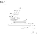
- FIG. 1 schematically illustrates an AM apparatus for manufacturing a fabrication object according to one embodiment.
- an AM apparatus 100 includes a base plate 102.
- a fabrication object M will be fabricated on the base plate 102.
- the base plate 102 can be a plate made from any material capable of supporting the fabrication object M.
- the base plate 102 is disposed on an XY stage 104.
- the XY stage 104 is a stage 104 movable in two directions (an x direction and a y direction) perpendicular to each other in a horizontal plane.
- the XY stage 104 may be coupled with a lift mechanism movable in the height direction (a z direction). Alternatively, in one embodiment, the XY stage 104 may be omitted.
- the AM apparatus 100 includes a DED head 200 as illustrated in Fig. 1 .
- the DED head 200 is connected to a laser source 202, a material powder source 204, and a gas source 206.
- the DED head 200 includes a DED nozzle 250.
- the DED nozzle 250 is configured to inject laser, material powder, and gas from the laser source 202, the material powder source 204, and the gas source 206, respectively.
- the DED head 200 can be any DED head, and, for example, a known DED head can be used as it.
- the DED head 200 is coupled with a movement mechanism 220, and is movably configured.
- the movement mechanism 220 can be any movement mechanism, and, for example, may be a movement mechanism capable of moving the DED head 200 along a specific axis such as a rail or may be formed from a robot capable of moving the DED head 200 to an arbitrary position and in an arbitrary direction.
- the movement mechanism 220 can be configured to be able to move the DED head 200 along perpendicular three axes.
- the AM apparatus 100 includes a control device 170 as illustrated in Fig. 1 .
- the control device 170 is configured to control the operations of various kinds of operation mechanisms of the AM apparatus 100, such as the above-described DED head 200 and various kinds of operation mechanisms.
- the control device 170 can be constituted by a general computer or a dedicated computer.
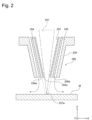
- Fig. 2 schematically illustrates a cross section of the DED nozzle 250 according to one embodiment.
- the DED nozzle 250 according to the illustrated embodiment is a DED nozzle main body 259 having a generally truncated conical shape.
- the DED nozzle 250 according to the illustrated embodiment includes a first passage 252 at the center of the DED nozzle main body 259.
- Laser 251 passes through the first passage 252. After passing through the first passage 252, the laser is emitted from a laser port 252a of the DED nozzle main body 259.
- the DED nozzle main body 259 includes a second passage 254 outside the first passage 252.
- the material powder and carrier gas for transporting the material powder pass through the second passage 254.
- the DED nozzle main body 259 includes a shield gas passage 256 outside the powder passage 254. Shield gas passes through the shield gas passage 256. After passing through the shield gas passage 256, the shield gas is emitted from a gas port 256a. In one embodiment, the DED nozzle 250 does not have to include the shield gas passage 256 and the gas port 256a.
- the powder passage 254 is configured in such a manner that the material powder discharged from the DED nozzle 250 is converged to substantially the same position as a focal point 251a of the laser 251.
- the flows of the material powder and the carrier gas are indicated by broken lines in Fig. 2 .
- the carrier gas can be inertial gas, such as argon gas or nitrogen gas. Argon gas heavier than air is further desirably used as the carrier gas. Using the inertial gas as the carrier gas allows a molten pool formed from the melted material powder to be covered with the inertial gas, thereby contributing to preventing oxidation. However, due to the flow of the carrier gas emitted from the powder port 254a, air outside it may be entrained therein.
- the DED nozzle 250 illustrated in Fig. 2 can prevent surrounding air from being entrained by supplying the shield gas at a low speed from the shield gas passage 256 provided outside the powder passage 254, from which the powder material and the carrier gas are discharged. Preventing the surrounding air (especially, oxygen) from being entrained by the carrier gas can contribute to preventing a metal oxide film from being generated at the time of the fabrication, and, further, allow a highly wettable molten pool to be formed.
- the flow of the shield gas is indicated by arrows in Fig. 2 .
- the shield gas can be the same kind of gas as the carrier gas.
- the AM apparatus 100 includes a powder supply mechanism 300.
- the powder supply mechanism 300 is configured to supply the material powder from the material powder source 204 to the second passage 254 of the DED nozzle 250.
- the second passage 254 of the DED nozzle 250 is divided into a plurality of regions circumferentially. In this case, desirably, the material powder is evenly supplied to the plurality of regions of the second passage 254.
- the second passage 254 of the DED nozzle 250 may be formed as a single passage 254 without being divided into the plurality of regions.
- the powder supply mechanism 300 may be configured to supply the material powder to the single second passage 254 formed in this manner via a plurality of circumferential positions of the second passage 254.
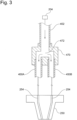
- Fig. 3 is a cross-sectional view illustrating piping of a powder supply mechanism 400 according to one reference example.
- the piping of the example illustrated in Fig. 3 includes a first pipe 402 connected to the material powder source 204, a plurality of second pipes 450A and 450B connected to the second passage 254 of the DED nozzle 250, and an adapter 470 for connecting the first pipe 402 and the second pipes 450.
- the adapter 470 includes a branch path 472 therein. After passing through the first pipe 402, the material powder is distributed to the plurality of second pipes 450A and 450B via the adapter 470 and then supplied to the DED nozzle 250.
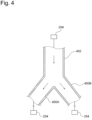
- Fig. 4 is a cross-sectional view illustrating piping of the powder supply mechanism 400 according to one reference example.
- the piping of the example illustrated in Fig. 4 includes the first pipe 402 connected to the material powder source 204, and the plurality of second pipes 450A and 450B connected to the second passage 254 of the DED nozzle 250.
- the plurality of second pipes 450A and 450B is connected to the first pipe 402 directly without the intervention of the adapter 470 illustrated in Fig. 3 .
- the cross-sectional area of the pipe drastically changes at the position of the branch portion where the material powder is distributed from the first pipe 402 to the plurality of second pipes 450. More specifically, the cross-sectional area is large from the first pipe 402 to the branch portion, and is small from the branch portion to each of the second pipes 450A and 450B. The presence of such a change in the cross-sectional area at the branch portion may lead to occurrence of an unstable swirl in the carrier gas flowing in the pipe, making it impossible to evenly distribute the material powder to the plurality of second pipes 450A and 450B.
- the material powder may be deposited on a part of the adapter 470.
- the material powder deposited on the adapter 470 may accidentally flow down into one of the second pipes 450A and 450b.
- the material powder may also be unable to be evenly distributed to the plurality of second pipes 450A and 450B.
- the material powder is easily deposited onto the adapter 470.
- the powder supply mechanism is mostly designed in such a manner that the powder material and the carrier gas emitted from the DED nozzle 250 flow at 30 m/s to 40 m/s.
- the carrier gas flows at 30 m/s to 40 m/s or so, the powder material is at low risk of being deposited on the adapter 470.
- the powder material and the carrier gas may be supplied to the DED nozzle 250 at a speed low enough to prevent the powder material present in the fabrication region from being blown off.
- the powder supply mechanism even based on the DED method, is designed in such a manner that the powder material and the carrier gas emitted from the DED nozzle 250 flow at as low speed as 10 m/s or lower or 5 m/s or lower. It is desirable that the material powder can be stably supplied to the DED nozzle 250 even under such a condition.
- Fig. 5A is a cross-sectional view illustrating piping of the powder supply mechanism 300 according to one embodiment.
- the powder supply mechanism 300 illustrated in Fig. 5A includes a first pipe 302 connected to the material powder source 204, and a plurality of second pipes 350A and 350B connected to the second passage 254 of the DED nozzle 250.
- the first pipe 302 illustrated in Fig. 5A includes a separation wall 306 extending from a downstream end portion 304 toward the upstream side inside the first pipe 302.
- Fig. 5B is a cross-sectional perspective view cut away at a position 5B illustrated in Fig. 5A .
- Fig. 5C is a cross-sectional perspective view cut away at a position 5C illustrated in Fig. 5A .
- Fig. 5D is a cross-sectional perspective view cut away at a position 5D illustrated in Fig. 5A .
- the separation wall 306 is formed so as to divide the inner flow passage at the end portion 304 of the first pipe 302 into halves to define conduits 302A and 302B.
- the separation wall 306 may be configured to divide the inner flow passage at the end portion 304 of the first pipe 302 into thirds, fourths, or the like to define any number of regions.
- the conduits 302A and 302B divided by the separation wall 306 are each formed into a flow passage semi-circular in cross section.
- the conduits 302A and 302B divided by the separation wall 306 are formed so as to gradually become circular in cross section from the position 5C toward the end portion 304 of the first pipe 302.
- the conduits 302A and 302B divided by the separation wall 306 are connected to the second pipes 350A and 350B at the end portion 304 of the first pipe 302, respectively.
- a sum of the cross-sectional areas of the plurality of conduits 302A and 302B divided by the separation wall 306 of the first pipe 302 is approximately equal to the cross-sectional area of the conduit before the division.
- s represents the cross-sectional area of the conduit of the first pipe 302 before the division and the first pipe 302 is divided into n equal regions by the separation wall 306, each flow passage has a cross-sectional area of approximately s/n. Therefore, desirably, the separation wall 306 has a thin thickness.
- the cross-sectional area of the conduit little changes when divided into the plurality of flow passages in the first pipe 302. This can make it less likely for an unstable swirl to occur in the carrier gas flowing in the first pipe 302. Therefore, the powder material flowing together with the carrier gas in the first pipe 302 can be stably evenly distributed to the plurality of flow passages.
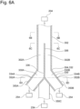
- Fig. 6A is a cross-sectional view illustrating piping of the powder supply mechanism 300 according to one embodiment.
- the powder supply mechanism 300 illustrated in Fig. 6A includes the first pipe 302 connected to the material powder source 204, and four second pipes 350A, 350B, 350C, and 350D connected to the second passage 254 of the DED nozzle 250.
- the second pipe 350D is omitted in Fig. 6A .
- the first pipe 302 illustrated in Fig. 6A includes the separation wall 306 extending from the downstream end portion 304 toward the upstream side inside the first pipe 302.
- Fig. 6B is a cross-sectional perspective view cut away at a position 6B illustrated in Fig. 6A .
- Fig. 6C is a cross-sectional perspective view cut away at a position 6C illustrated in Fig. 6A .
- the separation wall 306 is formed so as to divide the inner flow passage at the end portion 304 of the first pipe 302 into fourths to define the conduits 302A, 302B, 302C, and 302D.
- the separation wall 306 may be configured to divide the inner flow passage at the end portion 304 of the first pipe 302 into halves, thirds, or the like to define any number of regions.
- the first pipe 302 and the plurality of second pipes 350A, 350B, 350C, and 350D are connected via a transition portion 330.
- the downstream end portion 304 of the first pipe 302 is connected to an upstream end portion 332 of the transition portion 330, and upstream end portions 352A, 352B, 352C, and 352D of the second pipes 350A, 350B, 350C, and 350D are connected to downstream end portions 334A, 334B, 334C, and 334C of the transition portion 330, respectively.
- the transition portion 330 includes a transition portion separation wall 336 connected to the separation wall 306 of the first pipe 302.
- Fig. 6D is a cross-sectional perspective view cut away at a position 6D illustrated in Fig. 6A .
- the transition portion 330 is divided into four flow passages, flow passages 330A, 330B, 330C, and 330D by the transition portion separation wall 336, and these flow passages 330A, 330B, 330C, and 330D are connected to the second pipes 350A, 350B, 350C, and 350D, respectively.
- the first pipe 302 is divided into four conduits 302A, 302B, 302C, and 302D fan-shaped in cross section by the separation wall 306.
- the conduits 302A, 302B, 302C, and 302D identically fan-shaped in cross section extend until reaching the end portion 304 of the first pipe 302.
- the respective cross sections of the conduits 330A, 330B, 330C, and 330D are fan-shaped at the upstream end portion 332 of the transition portion 330, but are deformed so as to become more circular toward the downstream end portions 334A, 334B, 334C, and 334D.
- a sum of the cross-sectional areas of the plurality of conduits divided by the separation wall 306 inside the first pipe 302 is approximately equal to the cross-sectional area of the conduit before the division.
- s represents the cross-sectional area of the conduit of the first pipe 302 before the division and the first pipe 302 is divided into n equal regions by the separation wall 306, each flow passage has a cross-sectional area of approximately s/n. Therefore, desirably, the separation wall 306 has a thin thickness.
- the cross-sectional area of the flow passage changes at the transition portion 330.
- the flow passage is already divided into the plurality of conduits by the separation wall 306 at a position upstream of the end portion 304 of the first pipe 302, and therefore the material powder is already distributed by the separation wall 306 of the first pipe 302. This can make it less likely for the material powder to be unevenly distributed due to a disturbed flow of the carrier gas according to a change in the cross-sectional area of the flow passage at the transition portion 330.
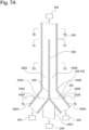
- Fig. 7A is a cross-sectional view illustrating piping of the powder supply mechanism 300 according to one embodiment.
- the powder supply mechanism 300 illustrated in Fig. 7A includes the first pipe 302 connected to the material powder source 204, and the four second pipes 350A, 350B, 350C, and 350D connected to the second passage 254 of the DED nozzle 250.
- the first pipe 302 illustrated in Fig. 7A includes the separation wall 306 extending from the downstream end portion 304 toward the upstream side inside the first pipe 302.
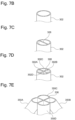
- Fig. 7B is a cross-sectional perspective view cut away at a position 7B illustrated in Fig. 7A .
- Fig. 7C is a cross-sectional perspective view cut away at a position 7C illustrated in Fig. 7A .
- Fig. 7D is a cross-sectional perspective view cut away at a position 7D illustrated in Fig. 7A .
- the separation wall 306 of the first pipe 302 divides the flow passage of the first pipe 302 into halves at the position 7C, which is the most upstream end portion of the separation wall 306. Then, as illustrated in Figs. 7A and 7D , the bisected flow passages are further each divided into halves at the position 7D, which is an intermediate position of the separation wall 306. As illustrated, in the present embodiment, the first pipe 302 is divided into the four conduits 302A, 302B, 302C, and 302D at the end portion 304.
- the separation wall 306 of the first pipe 302 may be formed so as to divide the flow passage into arbitrary n passages on the upstream side and further into arbitrary m passages at the intermediate position, thereby sectioning the flow passage into n x m passages in total at the end portion 304 of the first pipe 302.
- n and m are natural numbers equal to or larger than 2.
- the first pipe 302 and the plurality of second pipes 350A, 350B, 350C, and 350D are connected via the transition portion 330.
- Fig. 7E is a cross-sectional perspective view cut away at a position 7E illustrated in Fig. 7A .
- the configuration of the transition portion 330 is similar to the embodiment illustrated in Figs. 6A to 6D , and therefore the description thereof will be omitted here.
- a sum of the cross-sectional areas of the plurality of conduits divided by the separation wall 306 inside the first pipe 302 is approximately equal to the cross-sectional area of the conduit before the division.
- s represents the cross-sectional area of the conduit of the first pipe 302 before the division and the first pipe 302 is divided into n equal regions by the separation wall 306 at the end portion 304
- each flow passage has a cross-sectional area of approximately s/n. Therefore, desirably, the separation wall 306 has a thin thickness.
- the cross-sectional area of the flow passage changes at the transition portion 330.
- the flow passage is already divided into the plurality of conduits by the separation wall 306 at a position upstream of the end portion 304 of the first pipe 302, and therefore the material powder is already distributed by the separation wall 306 of the first pipe 302. This can make it less likely for the material powder to be unevenly distributed due to a disturbed flow of the carrier gas according to a change in the cross-sectional area of the flow passage at the transition portion 330.
- the flow passage is divided at the upstream end portion and the intermediate position of the separation wall 306 in two steps, unlike the embodiment illustrated in Figs. 6A to 6D . This can reduce an area of the end portion of the separation wall 306 against which the material powder collides, thereby further reducing the unevenness of the distribution of the material powder compared to when the flow passage is divided into many passages all at once.
- the separation wall 306 of the first pipe 302 is configured in such a manner that a length thereof extending upstream from the downstream end portion 304 of the first pipe 302 is equal to or longer than ⁇ , assuming that ⁇ represents the diameter of the first pipe 302.
- the first pipe 302 including the separation wall 306 formed in the above-described manner, the second pipes 350, and the transition portion 330 can be made from the same kind of material as the material powder supplied to the AM apparatus.
- the first pipe 302, the second pipes 350, and the transition portion 330 can be made from a metal material or a resin material.
- the first pipe 302, the second pipes 350, and the transition portion 330 can be made from SUS.
- the first pipe 302 including the separation wall 306, the second pipes 350, and the transition portion 330 are made from an electrically conductive material for antistatic purpose.
- these members can be made from a resin material or a metal material provided with electric conductivity. Further, desirably, these materials are used in an electrically grounded state in the AM apparatus.
- the first pipe 302, the second pipes 350, and the transition portion 330 are formed by a known AM method. Manufacturing the first pipe 302, the second pipes 350, and the transition portion 330 by the AM method can facilitate smooth formation of the connection portion between the pipes and the change in the shape of the transition portion.
Landscapes
- Engineering & Computer Science (AREA)
- Chemical & Material Sciences (AREA)
- Manufacturing & Machinery (AREA)
- Materials Engineering (AREA)
- Physics & Mathematics (AREA)
- Optics & Photonics (AREA)
- Mechanical Engineering (AREA)
- Plasma & Fusion (AREA)
- Powder Metallurgy (AREA)
- Nozzles (AREA)
Abstract
Description
- The present application relates to an AM apparatus. The present application claims priority under the Paris Convention to
Japanese Patent Application No. 2022-021490 filed on February 15, 2022 Japanese Patent Application No. 2022-021490 - There are known techniques for directly fabricating a three-dimensional object based on three-dimensional data on a computer that expresses the three-dimensional object. For example, the Additive Manufacturing (AM) technique is known. One example thereof is Direct Energy Deposition (DED) as the AM technique employing the deposition method. DED is a technique that carries out fabrication by melting and solidifying a metal material together with a base material using an appropriate heat source while supplying the metal material locally. Another example of the AM technique is Powder Bed Fusion (PBF). According to PBF, each layer of the three-dimensional object is fabricated by subjecting two-dimensionally bedded metal powder to irradiation of a fabrication target portion thereof with a laser beam or an electron beam serving as a heat source, and melting and solidifying or sintering the metal powder. In PBF, the desired three-dimensional object can be fabricated by repeating such a process.
-
- PTL 1:
Japanese Patent Application Laid-Open No. 2018-94623 - PTL 2:
Japanese Patent Application Laid-Open No. 2018-90376 - In the DED method, generally, a laser or electron beam serving as a heat source is supplied from a DED nozzle to a predetermined location. Further, powder used as the material is supplied from the DED nozzle to the predetermined location together with carrier gas. A powder passage through which the powder used as the material passes, and a powder port for ejecting the powder are formed in the DED nozzle. A plurality of powder passages and a plurality of powder ports may be formed in the DED nozzle to evenly supply the powder used as the material to the predetermined location. In this case, it is desirable to evenly supply the powder to each of the powder passages. One of objects of the present application is to provide a technique for evenly supplying powder used as a material to a DED nozzle.
- According to one aspect, an AM apparatus configured to manufacture a fabrication object is provided. This AM apparatus includes a DED nozzle. The DED nozzle includes a powder port provided at a distal end of a main body of the DED nozzle and configured to eject a powder material therefrom, and a powder passage provided in communication with the powder port and configured to allow the powder material to pass through inside the main body of the DED nozzle. The AM apparatus further includes a first pipe, a separation wall extending from an end portion of the first pipe toward an upstream side inside the first pipe, and a plurality of second pipes connected to the end portion of the first pipe. The separation wall divides the end portion of the first pipe into a plurality of regions, and the plurality of second pipes is connected to the plurality of regions of the first pipe, respectively. The second pipes are connected to the powder passage of the DED nozzle.
-
-
Fig. 1 schematically illustrates an AM apparatus for manufacturing a fabrication object according to one embodiment. -
Fig. 2 schematically illustrates a cross section of a DED nozzle according to one embodiment. -
Fig. 3 is a cross-sectional view schematically illustrating piping of a powder supply mechanism according to one reference example. -
Fig. 4 is a cross-sectional view schematically illustrating piping of a powder supply mechanism according to one reference example. -
Fig. 5A is a cross-sectional view schematically illustrating piping of a powder supply mechanism according to one embodiment. -
Fig. 5B is a cross-sectional perspective view cut away at aposition 5B illustrated inFig. 5A . -
Fig. 5C is a cross-sectional perspective view cut away at aposition 5C illustrated inFig. 5A . -
Fig. 5D is a cross-sectional perspective view cut away at aposition 5D illustrated inFig. 5A . -
Fig. 6A is a cross-sectional view schematically illustrating piping of a powder supply mechanism according to one embodiment. -
Fig. 6B is a cross-sectional perspective view cut away at aposition 6B illustrated inFig. 6A . -
Fig. 6C is a cross-sectional perspective view cut away at aposition 6C illustrated inFig. 6A . -
Fig. 6D is a cross-sectional perspective view cut away at aposition 6D illustrated inFig. 6A . -
Fig. 7A is a cross-sectional view schematically illustrating piping of a powder supply mechanism according to one embodiment. -
Fig. 7B is a cross-sectional perspective view cut away at aposition 7B illustrated inFig. 7A . -
Fig. 7C is a cross-sectional perspective view cut away at aposition 7C illustrated inFig. 7A . -
Fig. 7D is a cross-sectional perspective view cut away at aposition 7D illustrated inFig. 7A . -
Fig. 7E is a cross-sectional perspective view cut away at aposition 7E illustrated inFig. 7A . - In the following description, embodiments of an AM apparatus for manufacturing a fabrication object according to the present invention will be described with reference to the accompanying drawings. In the accompanying drawings, the same or similar components will be indicated by the same or similar reference numerals, and redundant descriptions regarding the same or similar components may be omitted in the description of each of the embodiments. Further, features described in each of the embodiments are also applicable to other embodiments in so far as they do not contradict each other.
-
Fig. 1 schematically illustrates an AM apparatus for manufacturing a fabrication object according to one embodiment. As illustrated inFig. 1 , anAM apparatus 100 includes abase plate 102. A fabrication object M will be fabricated on thebase plate 102. Thebase plate 102 can be a plate made from any material capable of supporting the fabrication object M. In one embodiment, thebase plate 102 is disposed on anXY stage 104. TheXY stage 104 is astage 104 movable in two directions (an x direction and a y direction) perpendicular to each other in a horizontal plane. TheXY stage 104 may be coupled with a lift mechanism movable in the height direction (a z direction). Alternatively, in one embodiment, theXY stage 104 may be omitted. - In one embodiment, the
AM apparatus 100 includes aDED head 200 as illustrated inFig. 1 . TheDED head 200 is connected to alaser source 202, amaterial powder source 204, and agas source 206. TheDED head 200 includes aDED nozzle 250. TheDED nozzle 250 is configured to inject laser, material powder, and gas from thelaser source 202, thematerial powder source 204, and thegas source 206, respectively. - The
DED head 200 can be any DED head, and, for example, a known DED head can be used as it. TheDED head 200 is coupled with amovement mechanism 220, and is movably configured. Themovement mechanism 220 can be any movement mechanism, and, for example, may be a movement mechanism capable of moving theDED head 200 along a specific axis such as a rail or may be formed from a robot capable of moving theDED head 200 to an arbitrary position and in an arbitrary direction. As one embodiment, themovement mechanism 220 can be configured to be able to move theDED head 200 along perpendicular three axes. - The
AM apparatus 100 according to one embodiment includes acontrol device 170 as illustrated inFig. 1 . Thecontrol device 170 is configured to control the operations of various kinds of operation mechanisms of theAM apparatus 100, such as the above-describedDED head 200 and various kinds of operation mechanisms. Thecontrol device 170 can be constituted by a general computer or a dedicated computer. -
Fig. 2 schematically illustrates a cross section of theDED nozzle 250 according to one embodiment. TheDED nozzle 250 according to the illustrated embodiment is a DED nozzlemain body 259 having a generally truncated conical shape. TheDED nozzle 250 according to the illustrated embodiment includes afirst passage 252 at the center of the DED nozzlemain body 259.Laser 251 passes through thefirst passage 252. After passing through thefirst passage 252, the laser is emitted from alaser port 252a of the DED nozzlemain body 259. Further, the DED nozzlemain body 259 includes asecond passage 254 outside thefirst passage 252. The material powder and carrier gas for transporting the material powder pass through thesecond passage 254. After passing through thesecond passage 254, the material powder is emitted from apowder port 254a. Further, the DED nozzlemain body 259 includes ashield gas passage 256 outside thepowder passage 254. Shield gas passes through theshield gas passage 256. After passing through theshield gas passage 256, the shield gas is emitted from agas port 256a. In one embodiment, theDED nozzle 250 does not have to include theshield gas passage 256 and thegas port 256a. - The
powder passage 254 is configured in such a manner that the material powder discharged from theDED nozzle 250 is converged to substantially the same position as afocal point 251a of thelaser 251. The flows of the material powder and the carrier gas are indicated by broken lines inFig. 2 . The carrier gas can be inertial gas, such as argon gas or nitrogen gas. Argon gas heavier than air is further desirably used as the carrier gas. Using the inertial gas as the carrier gas allows a molten pool formed from the melted material powder to be covered with the inertial gas, thereby contributing to preventing oxidation. However, due to the flow of the carrier gas emitted from thepowder port 254a, air outside it may be entrained therein. In light thereof, theDED nozzle 250 illustrated inFig. 2 can prevent surrounding air from being entrained by supplying the shield gas at a low speed from theshield gas passage 256 provided outside thepowder passage 254, from which the powder material and the carrier gas are discharged. Preventing the surrounding air (especially, oxygen) from being entrained by the carrier gas can contribute to preventing a metal oxide film from being generated at the time of the fabrication, and, further, allow a highly wettable molten pool to be formed. The flow of the shield gas is indicated by arrows inFig. 2 . The shield gas can be the same kind of gas as the carrier gas. - In one embodiment, the
AM apparatus 100 includes a powder supply mechanism 300. The powder supply mechanism 300 is configured to supply the material powder from thematerial powder source 204 to thesecond passage 254 of theDED nozzle 250. In one embodiment, thesecond passage 254 of theDED nozzle 250 is divided into a plurality of regions circumferentially. In this case, desirably, the material powder is evenly supplied to the plurality of regions of thesecond passage 254. Alternatively, in one embodiment, thesecond passage 254 of theDED nozzle 250 may be formed as asingle passage 254 without being divided into the plurality of regions. The powder supply mechanism 300 may be configured to supply the material powder to the singlesecond passage 254 formed in this manner via a plurality of circumferential positions of thesecond passage 254. -
Fig. 3 is a cross-sectional view illustrating piping of a powder supply mechanism 400 according to one reference example. The piping of the example illustrated inFig. 3 includes afirst pipe 402 connected to thematerial powder source 204, a plurality ofsecond pipes second passage 254 of theDED nozzle 250, and anadapter 470 for connecting thefirst pipe 402 and the second pipes 450. As illustrated inFig. 3 , theadapter 470 includes abranch path 472 therein. After passing through thefirst pipe 402, the material powder is distributed to the plurality ofsecond pipes adapter 470 and then supplied to theDED nozzle 250. -
Fig. 4 is a cross-sectional view illustrating piping of the powder supply mechanism 400 according to one reference example. The piping of the example illustrated inFig. 4 includes thefirst pipe 402 connected to thematerial powder source 204, and the plurality ofsecond pipes second passage 254 of theDED nozzle 250. In the reference example illustrated inFig. 4 , the plurality ofsecond pipes first pipe 402 directly without the intervention of theadapter 470 illustrated inFig. 3 . - In the powder supply mechanism 400 according to the reference examples illustrated in
Figs. 3 and4 , the cross-sectional area of the pipe drastically changes at the position of the branch portion where the material powder is distributed from thefirst pipe 402 to the plurality of second pipes 450. More specifically, the cross-sectional area is large from thefirst pipe 402 to the branch portion, and is small from the branch portion to each of thesecond pipes second pipes - Further, in the case where the
adapter 470 including the branch portion is used like the reference example illustrated inFig. 3 , the material powder may be deposited on a part of theadapter 470. The material powder deposited on theadapter 470 may accidentally flow down into one of thesecond pipes 450A and 450b. In such a case, the material powder may also be unable to be evenly distributed to the plurality ofsecond pipes DED nozzle 250 at a low speed, the material powder is easily deposited onto theadapter 470. Generally, in the DED method, the powder supply mechanism is mostly designed in such a manner that the powder material and the carrier gas emitted from theDED nozzle 250 flow at 30 m/s to 40 m/s. When the carrier gas flows at 30 m/s to 40 m/s or so, the powder material is at low risk of being deposited on theadapter 470. However, for example, in a case where the fabrication is carried out according to the DED method under a condition that the powder material is present in the fabrication region, the powder material and the carrier gas may be supplied to theDED nozzle 250 at a speed low enough to prevent the powder material present in the fabrication region from being blown off. For example, it is possible that the powder supply mechanism, even based on the DED method, is designed in such a manner that the powder material and the carrier gas emitted from theDED nozzle 250 flow at as low speed as 10 m/s or lower or 5 m/s or lower. It is desirable that the material powder can be stably supplied to theDED nozzle 250 even under such a condition. -
Fig. 5A is a cross-sectional view illustrating piping of the powder supply mechanism 300 according to one embodiment. The powder supply mechanism 300 illustrated inFig. 5A includes afirst pipe 302 connected to thematerial powder source 204, and a plurality ofsecond pipes second passage 254 of theDED nozzle 250. - The
first pipe 302 illustrated inFig. 5A includes aseparation wall 306 extending from adownstream end portion 304 toward the upstream side inside thefirst pipe 302.Fig. 5B is a cross-sectional perspective view cut away at aposition 5B illustrated inFig. 5A .Fig. 5C is a cross-sectional perspective view cut away at aposition 5C illustrated inFig. 5A .Fig. 5D is a cross-sectional perspective view cut away at aposition 5D illustrated inFig. 5A . As illustrated, theseparation wall 306 is formed so as to divide the inner flow passage at theend portion 304 of thefirst pipe 302 into halves to defineconduits separation wall 306 may be configured to divide the inner flow passage at theend portion 304 of thefirst pipe 302 into thirds, fourths, or the like to define any number of regions. - At the
position 5C illustrated inFig. 5A , theconduits separation wall 306 are each formed into a flow passage semi-circular in cross section. In the illustrated embodiment, theconduits separation wall 306 are formed so as to gradually become circular in cross section from theposition 5C toward theend portion 304 of thefirst pipe 302. As illustrated, theconduits separation wall 306 are connected to thesecond pipes end portion 304 of thefirst pipe 302, respectively. - In the embodiment illustrated in
Figs. 5A to 5D , a sum of the cross-sectional areas of the plurality ofconduits separation wall 306 of thefirst pipe 302 is approximately equal to the cross-sectional area of the conduit before the division. Assuming that s represents the cross-sectional area of the conduit of thefirst pipe 302 before the division and thefirst pipe 302 is divided into n equal regions by theseparation wall 306, each flow passage has a cross-sectional area of approximately s/n. Therefore, desirably, theseparation wall 306 has a thin thickness. - As described above, the cross-sectional area of the conduit little changes when divided into the plurality of flow passages in the
first pipe 302. This can make it less likely for an unstable swirl to occur in the carrier gas flowing in thefirst pipe 302. Therefore, the powder material flowing together with the carrier gas in thefirst pipe 302 can be stably evenly distributed to the plurality of flow passages. -
Fig. 6A is a cross-sectional view illustrating piping of the powder supply mechanism 300 according to one embodiment. The powder supply mechanism 300 illustrated inFig. 6A includes thefirst pipe 302 connected to thematerial powder source 204, and foursecond pipes second passage 254 of theDED nozzle 250. However, thesecond pipe 350D is omitted inFig. 6A . - The
first pipe 302 illustrated inFig. 6A includes theseparation wall 306 extending from thedownstream end portion 304 toward the upstream side inside thefirst pipe 302.Fig. 6B is a cross-sectional perspective view cut away at aposition 6B illustrated inFig. 6A .Fig. 6C is a cross-sectional perspective view cut away at aposition 6C illustrated inFig. 6A . As illustrated, theseparation wall 306 is formed so as to divide the inner flow passage at theend portion 304 of thefirst pipe 302 into fourths to define theconduits separation wall 306 may be configured to divide the inner flow passage at theend portion 304 of thefirst pipe 302 into halves, thirds, or the like to define any number of regions. - In the embodiment illustrated in
Fig. 6A , thefirst pipe 302 and the plurality ofsecond pipes transition portion 330. As illustrated inFig. 6A , thedownstream end portion 304 of thefirst pipe 302 is connected to an upstream end portion 332 of thetransition portion 330, andupstream end portions second pipes downstream end portions transition portion 330, respectively. As illustrated, thetransition portion 330 includes a transitionportion separation wall 336 connected to theseparation wall 306 of thefirst pipe 302. In other words, theseparation wall 306 of thefirst pipe 302 is extended to thetransition portion 330, and theseparation wall 306 extended to thetransition portion 330 will be referred to as the transitionportion separation wall 336.Fig. 6D is a cross-sectional perspective view cut away at aposition 6D illustrated inFig. 6A . As illustrated, thetransition portion 330 is divided into four flow passages,flow passages portion separation wall 336, and theseflow passages second pipes - In the embodiment illustrated in
Figs. 6A to 6D , thefirst pipe 302 is divided into fourconduits separation wall 306. In the illustrated embodiment, theconduits end portion 304 of thefirst pipe 302. In the illustrated embodiment, the respective cross sections of theconduits transition portion 330, but are deformed so as to become more circular toward thedownstream end portions - In the embodiment illustrated in
Figs. 6A to 6D , a sum of the cross-sectional areas of the plurality of conduits divided by theseparation wall 306 inside thefirst pipe 302 is approximately equal to the cross-sectional area of the conduit before the division. Assuming that s represents the cross-sectional area of the conduit of thefirst pipe 302 before the division and thefirst pipe 302 is divided into n equal regions by theseparation wall 306, each flow passage has a cross-sectional area of approximately s/n. Therefore, desirably, theseparation wall 306 has a thin thickness. - In the embodiment illustrated in
Figs. 6A to 6D , the cross-sectional area of the flow passage changes at thetransition portion 330. However, the flow passage is already divided into the plurality of conduits by theseparation wall 306 at a position upstream of theend portion 304 of thefirst pipe 302, and therefore the material powder is already distributed by theseparation wall 306 of thefirst pipe 302. This can make it less likely for the material powder to be unevenly distributed due to a disturbed flow of the carrier gas according to a change in the cross-sectional area of the flow passage at thetransition portion 330. -
Fig. 7A is a cross-sectional view illustrating piping of the powder supply mechanism 300 according to one embodiment. The powder supply mechanism 300 illustrated inFig. 7A includes thefirst pipe 302 connected to thematerial powder source 204, and the foursecond pipes second passage 254 of theDED nozzle 250. - The
first pipe 302 illustrated inFig. 7A includes theseparation wall 306 extending from thedownstream end portion 304 toward the upstream side inside thefirst pipe 302.Fig. 7B is a cross-sectional perspective view cut away at aposition 7B illustrated inFig. 7A .Fig. 7C is a cross-sectional perspective view cut away at aposition 7C illustrated inFig. 7A .Fig. 7D is a cross-sectional perspective view cut away at aposition 7D illustrated inFig. 7A . - As illustrated in
Figs. 7A and7C , theseparation wall 306 of thefirst pipe 302 divides the flow passage of thefirst pipe 302 into halves at theposition 7C, which is the most upstream end portion of theseparation wall 306. Then, as illustrated inFigs. 7A and7D , the bisected flow passages are further each divided into halves at theposition 7D, which is an intermediate position of theseparation wall 306. As illustrated, in the present embodiment, thefirst pipe 302 is divided into the fourconduits end portion 304. As another embodiment, theseparation wall 306 of thefirst pipe 302 may be formed so as to divide the flow passage into arbitrary n passages on the upstream side and further into arbitrary m passages at the intermediate position, thereby sectioning the flow passage into n x m passages in total at theend portion 304 of thefirst pipe 302. In this case, n and m are natural numbers equal to or larger than 2. - In the embodiment illustrated in
Fig. 7A , thefirst pipe 302 and the plurality ofsecond pipes transition portion 330. -
Fig. 7E is a cross-sectional perspective view cut away at aposition 7E illustrated inFig. 7A . The configuration of thetransition portion 330 is similar to the embodiment illustrated inFigs. 6A to 6D , and therefore the description thereof will be omitted here. - In the embodiment illustrated in
Figs. 7A to 7E , a sum of the cross-sectional areas of the plurality of conduits divided by theseparation wall 306 inside thefirst pipe 302 is approximately equal to the cross-sectional area of the conduit before the division. Assuming that s represents the cross-sectional area of the conduit of thefirst pipe 302 before the division and thefirst pipe 302 is divided into n equal regions by theseparation wall 306 at theend portion 304, each flow passage has a cross-sectional area of approximately s/n. Therefore, desirably, theseparation wall 306 has a thin thickness. - In the embodiment illustrated in
Figs. 7A to 7E , the cross-sectional area of the flow passage changes at thetransition portion 330. However, the flow passage is already divided into the plurality of conduits by theseparation wall 306 at a position upstream of theend portion 304 of thefirst pipe 302, and therefore the material powder is already distributed by theseparation wall 306 of thefirst pipe 302. This can make it less likely for the material powder to be unevenly distributed due to a disturbed flow of the carrier gas according to a change in the cross-sectional area of the flow passage at thetransition portion 330. In the embodiment illustrated inFigs. 7A to 7E , the flow passage is divided at the upstream end portion and the intermediate position of theseparation wall 306 in two steps, unlike the embodiment illustrated inFigs. 6A to 6D . This can reduce an area of the end portion of theseparation wall 306 against which the material powder collides, thereby further reducing the unevenness of the distribution of the material powder compared to when the flow passage is divided into many passages all at once. - Desirably, in any of the above-described embodiments, the
separation wall 306 of thefirst pipe 302 is configured in such a manner that a length thereof extending upstream from thedownstream end portion 304 of thefirst pipe 302 is equal to or longer than ϕ, assuming that ϕ represents the diameter of thefirst pipe 302. - In one embodiment, the
first pipe 302 including theseparation wall 306 formed in the above-described manner, the second pipes 350, and thetransition portion 330 can be made from the same kind of material as the material powder supplied to the AM apparatus. For example, thefirst pipe 302, the second pipes 350, and thetransition portion 330 can be made from a metal material or a resin material. As one embodiment, thefirst pipe 302, the second pipes 350, and thetransition portion 330 can be made from SUS. Further, in one embodiment, desirably, thefirst pipe 302 including theseparation wall 306, the second pipes 350, and thetransition portion 330 are made from an electrically conductive material for antistatic purpose. For example, these members can be made from a resin material or a metal material provided with electric conductivity. Further, desirably, these materials are used in an electrically grounded state in the AM apparatus. - As one embodiment, the
first pipe 302, the second pipes 350, and thetransition portion 330 are formed by a known AM method. Manufacturing thefirst pipe 302, the second pipes 350, and thetransition portion 330 by the AM method can facilitate smooth formation of the connection portion between the pipes and the change in the shape of the transition portion. - At least the following technical ideas can be recognized from the above-described embodiments.
- [Configuration 1] According to a configuration 1, an AM apparatus for manufacturing a fabrication object is provided. The AM apparatus includes a DED nozzle. The DED nozzle includes a powder port provided at a distal end of a main body of the DED nozzle and configured to eject a powder material therefrom, and a powder passage provided in communication with the powder port and configured to allow the powder material to pass through inside the main body of the DED nozzle. The AM apparatus further includes a first pipe, a separation wall extending from an end portion of the first pipe toward an upstream side inside the first pipe, and a plurality of second pipes connected to the end portion of the first pipe. The separation wall divides the end portion of the first pipe into a plurality of regions, and the plurality of second pipes is connected to the plurality of regions of the first pipe, respectively. The second pipes are connected to the powder passage of the DED nozzle.
- [Configuration 2] According to a configuration 2, in the AM apparatus according to the configuration 1, a length of the separation wall extending upstream from the end portion of the first pipe is longer than ϕ, assuming that ϕ represents an inner diameter of the first pipe.
- [Configuration 3] According to a configuration 3, in the AM apparatus according to the configuration 1 or 2, the separation wall of the first pipe includes a first separation wall equally dividing an inside of the first pipe into a plurality of regions, and a second separation wall further dividing each of the regions equally divided by the first separation wall into a plurality of regions.
- [Configuration 4] According to a configuration 4, in the AM apparatus according to any one of the configurations 1 to 3, the first pipe and the second pipe are connected via a transition portion. The transition portion includes a transition portion separation wall connected to the separation wall of the first pipe and is divided into a plurality of regions by the transition portion separation wall, and the plurality of second pipes is connected to the plurality of regions of the transition portion, respectively.
- [Configuration 5] According to a configuration 5, in the AM apparatus according to the configuration 4, a cross-sectional area of each of the plurality of regions at the branch portion is approximately s/n, assuming that s represents an inner cross-sectional area of the first pipe and n represents the number of the plurality of regions at the end portion of the first pipe.
- [Configuration 6] According to a configuration 6, in the AM apparatus according to any one of the configurations 1 to 5, the AM apparatus is configured in such a manner that the powder material and carrier gas are discharged from the powder port of the DED nozzle at a flow speed equal to or lower than 10 m/s.
-
- 100
- AM apparatus
- 200
- head
- 202
- laser source
- 204
- material powder source
- 206
- gas source
- 250
- nozzle
- 252
- first passage
- 254
- second passage
- 300
- powder supply mechanism
- 302
- first pipe
- 304
- end portion
- 306
- separation wall
- 330
- transition portion
- 332
- end portion
- 336
- transition portion separation wall
- 350
- second pipe
- M
- fabrication object
Claims (6)
- An AM apparatus for manufacturing a fabrication object, the AM apparatus comprising:a DED nozzle, the DED nozzle includinga powder port provided at a distal end of a main body of the DED nozzle and configured to eject a powder material therefrom, and a powder passage provided in communication with the powder port and configured to allow the powder material to pass through inside the main body of the DED nozzle,the AM apparatus further comprising:a first pipe;a separation wall extending from an end portion of the first pipe toward an upstream side inside the first pipe; anda plurality of second pipes connected to the end portion of the first pipe,wherein the separation wall divides the end portion of the first pipe into a plurality of regions, and the plurality of second pipes is connected to the plurality of regions of the first pipe, respectively, andwherein the second pipes are connected to the powder passage of the DED nozzle.
- The AM apparatus according to claim 1, wherein a length of the separation wall extending upstream from the end portion of the first pipe is longer than ϕ, assuming that ϕ represents an inner diameter of the first pipe.
- The AM apparatus according to claim 1 or 2, wherein the separation wall of the first pipe includesa first separation wall equally dividing an inside of the first pipe into a plurality of regions, anda second separation wall further dividing each of the regions equally divided by the first separation wall into a plurality of regions.
- The AM apparatus according to any one of claims 1 to 3, wherein the first pipe and the second pipe are connected via a transition portion, and
wherein the transition portion includes a transition portion separation wall connected to the separation wall of the first pipe and is divided into a plurality of regions by the transition portion separation wall, and the plurality of second pipes is connected to the plurality of regions of the transition portion, respectively. - The AM apparatus according to claim 4, wherein a cross-sectional area of each of the plurality of regions at the branch portion is approximately s/n, assuming that s represents an inner cross-sectional area of the first pipe and n represents the number of the plurality of regions at the end portion of the first pipe.
- The AM apparatus according to any one of claims 1 to 5, wherein the AM apparatus is configured in such a manner that the powder material and carrier gas are discharged from the powder port of the DED nozzle at a flow speed equal to or lower than 10 m/s.
Applications Claiming Priority (2)
| Application Number | Priority Date | Filing Date | Title |
|---|---|---|---|
| JP2022021490A JP2023118507A (en) | 2022-02-15 | 2022-02-15 | AM device |
| PCT/JP2022/041286 WO2023157393A1 (en) | 2022-02-15 | 2022-11-07 | Am device |
Publications (2)
| Publication Number | Publication Date |
|---|---|
| EP4480609A1 true EP4480609A1 (en) | 2024-12-25 |
| EP4480609A4 EP4480609A4 (en) | 2026-03-04 |
Family
ID=87577927
Family Applications (1)
| Application Number | Title | Priority Date | Filing Date |
|---|---|---|---|
| EP22927287.7A Pending EP4480609A4 (en) | 2022-02-15 | 2022-11-07 | AM device |
Country Status (5)
| Country | Link |
|---|---|
| US (1) | US20250178094A1 (en) |
| EP (1) | EP4480609A4 (en) |
| JP (1) | JP2023118507A (en) |
| CN (1) | CN118829501A (en) |
| WO (1) | WO2023157393A1 (en) |
Family Cites Families (9)
| Publication number | Priority date | Publication date | Assignee | Title |
|---|---|---|---|---|
| US6263918B1 (en) * | 1999-04-29 | 2001-07-24 | The Regents Of The University Of California | Multiple feed powder splitter |
| US6811744B2 (en) * | 1999-07-07 | 2004-11-02 | Optomec Design Company | Forming structures from CAD solid models |
| JP5616769B2 (en) * | 2010-12-13 | 2014-10-29 | 株式会社日立製作所 | Laser processing head and overlay welding method |
| JP6706008B2 (en) | 2016-12-02 | 2020-06-03 | トヨタ自動車株式会社 | Powder feeder |
| GB201620735D0 (en) * | 2016-12-06 | 2017-01-18 | Advanced Laser Tech Ltd | Powder splitter |
| JP6855910B2 (en) | 2016-12-14 | 2021-04-07 | トヨタ自動車株式会社 | Laser clad processing equipment |
| FR3071745B1 (en) * | 2017-09-29 | 2022-07-22 | Fives Machining | DEVICE FOR DOSING ONE OR MORE POWDER(S), CORRESPONDING 3D PRINTER AND DOSING METHOD |
| FR3081365B1 (en) * | 2018-05-28 | 2020-05-22 | Beam | METAL POWDER JET ANALYSIS SYSTEM AND METHOD |
| JP7404187B2 (en) | 2020-07-22 | 2023-12-25 | 株式会社東芝 | Superconducting coils and superconducting coil devices |
-
2022
- 2022-02-15 JP JP2022021490A patent/JP2023118507A/en active Pending
- 2022-11-07 WO PCT/JP2022/041286 patent/WO2023157393A1/en not_active Ceased
- 2022-11-07 CN CN202280091603.XA patent/CN118829501A/en active Pending
- 2022-11-07 US US18/836,813 patent/US20250178094A1/en active Pending
- 2022-11-07 EP EP22927287.7A patent/EP4480609A4/en active Pending
Also Published As
| Publication number | Publication date |
|---|---|
| WO2023157393A1 (en) | 2023-08-24 |
| US20250178094A1 (en) | 2025-06-05 |
| EP4480609A4 (en) | 2026-03-04 |
| JP2023118507A (en) | 2023-08-25 |
| CN118829501A (en) | 2024-10-22 |
Similar Documents
| Publication | Publication Date | Title |
|---|---|---|
| EP1825948A2 (en) | Nozzle for laser net shape manufacturing | |
| US10780634B2 (en) | Nozzle, processing apparatus, and additive manufacturing apparatus | |
| US10259042B2 (en) | Device and method for the manufacture or repair of a three-dimensional object | |
| US11534968B2 (en) | Nozzle and additive manufacturing apparatus | |
| EP3342528B1 (en) | Nozzle for machining, machining head, and optical machining device | |
| WO2016151781A1 (en) | Processing nozzle, processing head, processing device | |
| KR20150063400A (en) | Powder nozzle for a laser powder welding device | |
| US11484970B2 (en) | Additive manufacturing system and method of forming an object in a powder bed | |
| CN111372757A (en) | Additive manufacturing method and apparatus | |
| EP3372334A1 (en) | Apparatuses and systems for net shape manufacturing | |
| US20250178094A1 (en) | Am apparatus | |
| CN114364504A (en) | Melt distributor | |
| EP4026634A1 (en) | Am device | |
| EP4155009A1 (en) | Am device and am method | |
| US12365033B2 (en) | Nozzle and additive manufacturing apparatus | |
| US10065201B2 (en) | Processing nozzle and optical machining apparatus | |
| EP4279210A1 (en) | Ded nozzle used in am device, and adapter that can be attached to and detached from ded nozzle | |
| US20220288851A1 (en) | Nozzle and modeling device | |
| CN114144533A (en) | Oxygen gas transfer device, method for manufacturing oxygen gas transfer device, laval nozzle, and method for manufacturing laval nozzle | |
| US7342195B2 (en) | Customizable ion fusion formation system and process | |
| JP2023540371A (en) | Translational movement of fluid bearing during optical fiber drawing process | |
| WO2022195881A1 (en) | Laminate-molded article, method for producing laminate-molded article and laminate-molding device | |
| JP7438888B2 (en) | AM device | |
| JP2021181211A (en) | AM device and AM method | |
| EP4450190A1 (en) | A device and method for laser 3d object printing |
Legal Events
| Date | Code | Title | Description |
|---|---|---|---|
| STAA | Information on the status of an ep patent application or granted ep patent |
Free format text: STATUS: THE INTERNATIONAL PUBLICATION HAS BEEN MADE |
|
| PUAI | Public reference made under article 153(3) epc to a published international application that has entered the european phase |
Free format text: ORIGINAL CODE: 0009012 |
|
| STAA | Information on the status of an ep patent application or granted ep patent |
Free format text: STATUS: REQUEST FOR EXAMINATION WAS MADE |
|
| 17P | Request for examination filed |
Effective date: 20240809 |
|
| AK | Designated contracting states |
Kind code of ref document: A1 Designated state(s): AL AT BE BG CH CY CZ DE DK EE ES FI FR GB GR HR HU IE IS IT LI LT LU LV MC ME MK MT NL NO PL PT RO RS SE SI SK SM TR |
|
| DAV | Request for validation of the european patent (deleted) | ||
| DAX | Request for extension of the european patent (deleted) | ||
| A4 | Supplementary search report drawn up and despatched |
Effective date: 20260130 |
|
| RIC1 | Information provided on ipc code assigned before grant |
Ipc: B22F 12/53 20210101AFI20260126BHEP Ipc: B22F 10/25 20210101ALI20260126BHEP Ipc: B33Y 30/00 20150101ALI20260126BHEP Ipc: B22F 12/55 20210101ALI20260126BHEP Ipc: B33Y 10/00 20150101ALI20260126BHEP Ipc: B23K 26/144 20140101ALI20260126BHEP Ipc: B23K 26/14 20140101ALI20260126BHEP Ipc: B23K 26/342 20140101ALI20260126BHEP |