EP4480425A1 - Ultrasonic treatment tool - Google Patents
Ultrasonic treatment tool Download PDFInfo
- Publication number
- EP4480425A1 EP4480425A1 EP23752827.8A EP23752827A EP4480425A1 EP 4480425 A1 EP4480425 A1 EP 4480425A1 EP 23752827 A EP23752827 A EP 23752827A EP 4480425 A1 EP4480425 A1 EP 4480425A1
- Authority
- EP
- European Patent Office
- Prior art keywords
- grip
- treatment tool
- ultrasonic treatment
- stress concentration
- biological tissue
- Prior art date
- Legal status (The legal status is an assumption and is not a legal conclusion. Google has not performed a legal analysis and makes no representation as to the accuracy of the status listed.)
- Pending
Links
Images






Classifications
-
- A—HUMAN NECESSITIES
- A61—MEDICAL OR VETERINARY SCIENCE; HYGIENE
- A61B—DIAGNOSIS; SURGERY; IDENTIFICATION
- A61B17/00—Surgical instruments, devices or methods
- A61B17/32—Surgical cutting instruments
- A61B17/320068—Surgical cutting instruments using mechanical vibrations, e.g. ultrasonic
- A61B17/320092—Surgical cutting instruments using mechanical vibrations, e.g. ultrasonic with additional movable means for clamping or cutting tissue, e.g. with a pivoting jaw
-
- A—HUMAN NECESSITIES
- A61—MEDICAL OR VETERINARY SCIENCE; HYGIENE
- A61B—DIAGNOSIS; SURGERY; IDENTIFICATION
- A61B17/00—Surgical instruments, devices or methods
- A61B17/32—Surgical cutting instruments
-
- A—HUMAN NECESSITIES
- A61—MEDICAL OR VETERINARY SCIENCE; HYGIENE
- A61B—DIAGNOSIS; SURGERY; IDENTIFICATION
- A61B17/00—Surgical instruments, devices or methods
- A61B2017/00017—Electrical control of surgical instruments
- A61B2017/00022—Sensing or detecting at the treatment site
- A61B2017/00026—Conductivity or impedance, e.g. of tissue
-
- A—HUMAN NECESSITIES
- A61—MEDICAL OR VETERINARY SCIENCE; HYGIENE
- A61B—DIAGNOSIS; SURGERY; IDENTIFICATION
- A61B17/00—Surgical instruments, devices or methods
- A61B2017/00017—Electrical control of surgical instruments
- A61B2017/00022—Sensing or detecting at the treatment site
- A61B2017/00084—Temperature
-
- A—HUMAN NECESSITIES
- A61—MEDICAL OR VETERINARY SCIENCE; HYGIENE
- A61B—DIAGNOSIS; SURGERY; IDENTIFICATION
- A61B17/00—Surgical instruments, devices or methods
- A61B2017/00017—Electrical control of surgical instruments
- A61B2017/00137—Details of operation mode
- A61B2017/00141—Details of operation mode continuous, e.g. wave
-
- A—HUMAN NECESSITIES
- A61—MEDICAL OR VETERINARY SCIENCE; HYGIENE
- A61B—DIAGNOSIS; SURGERY; IDENTIFICATION
- A61B17/00—Surgical instruments, devices or methods
- A61B2017/00367—Details of actuation of instruments, e.g. relations between pushing buttons, or the like, and activation of the tool, working tip, or the like
- A61B2017/00398—Details of actuation of instruments, e.g. relations between pushing buttons, or the like, and activation of the tool, working tip, or the like using powered actuators, e.g. stepper motors, solenoids
- A61B2017/00402—Piezo electric actuators
-
- A—HUMAN NECESSITIES
- A61—MEDICAL OR VETERINARY SCIENCE; HYGIENE
- A61B—DIAGNOSIS; SURGERY; IDENTIFICATION
- A61B17/00—Surgical instruments, devices or methods
- A61B2017/00743—Type of operation; Specification of treatment sites
- A61B2017/00778—Operations on blood vessels
- A61B2017/00783—Valvuloplasty
-
- A—HUMAN NECESSITIES
- A61—MEDICAL OR VETERINARY SCIENCE; HYGIENE
- A61B—DIAGNOSIS; SURGERY; IDENTIFICATION
- A61B17/00—Surgical instruments, devices or methods
- A61B2017/00831—Material properties
- A61B2017/00836—Material properties corrosion-resistant
-
- A—HUMAN NECESSITIES
- A61—MEDICAL OR VETERINARY SCIENCE; HYGIENE
- A61B—DIAGNOSIS; SURGERY; IDENTIFICATION
- A61B17/00—Surgical instruments, devices or methods
- A61B2017/00831—Material properties
- A61B2017/0088—Material properties ceramic
-
- A—HUMAN NECESSITIES
- A61—MEDICAL OR VETERINARY SCIENCE; HYGIENE
- A61B—DIAGNOSIS; SURGERY; IDENTIFICATION
- A61B17/00—Surgical instruments, devices or methods
- A61B2017/00831—Material properties
- A61B2017/00964—Material properties composite
-
- A—HUMAN NECESSITIES
- A61—MEDICAL OR VETERINARY SCIENCE; HYGIENE
- A61B—DIAGNOSIS; SURGERY; IDENTIFICATION
- A61B17/00—Surgical instruments, devices or methods
- A61B17/32—Surgical cutting instruments
- A61B17/320068—Surgical cutting instruments using mechanical vibrations, e.g. ultrasonic
- A61B2017/320072—Working tips with special features, e.g. extending parts
- A61B2017/320078—Tissue manipulating surface
-
- A—HUMAN NECESSITIES
- A61—MEDICAL OR VETERINARY SCIENCE; HYGIENE
- A61B—DIAGNOSIS; SURGERY; IDENTIFICATION
- A61B17/00—Surgical instruments, devices or methods
- A61B17/32—Surgical cutting instruments
- A61B17/320068—Surgical cutting instruments using mechanical vibrations, e.g. ultrasonic
- A61B2017/320089—Surgical cutting instruments using mechanical vibrations, e.g. ultrasonic node location
-
- A—HUMAN NECESSITIES
- A61—MEDICAL OR VETERINARY SCIENCE; HYGIENE
- A61B—DIAGNOSIS; SURGERY; IDENTIFICATION
- A61B17/00—Surgical instruments, devices or methods
- A61B17/32—Surgical cutting instruments
- A61B17/320068—Surgical cutting instruments using mechanical vibrations, e.g. ultrasonic
- A61B17/320092—Surgical cutting instruments using mechanical vibrations, e.g. ultrasonic with additional movable means for clamping or cutting tissue, e.g. with a pivoting jaw
- A61B2017/320094—Surgical cutting instruments using mechanical vibrations, e.g. ultrasonic with additional movable means for clamping or cutting tissue, e.g. with a pivoting jaw additional movable means performing clamping operation
-
- A—HUMAN NECESSITIES
- A61—MEDICAL OR VETERINARY SCIENCE; HYGIENE
- A61B—DIAGNOSIS; SURGERY; IDENTIFICATION
- A61B17/00—Surgical instruments, devices or methods
- A61B17/32—Surgical cutting instruments
- A61B17/320068—Surgical cutting instruments using mechanical vibrations, e.g. ultrasonic
- A61B17/320092—Surgical cutting instruments using mechanical vibrations, e.g. ultrasonic with additional movable means for clamping or cutting tissue, e.g. with a pivoting jaw
- A61B2017/320095—Surgical cutting instruments using mechanical vibrations, e.g. ultrasonic with additional movable means for clamping or cutting tissue, e.g. with a pivoting jaw with sealing or cauterizing means
Definitions
- the present invention relates to an ultrasonic treatment tool used in sealing and incising a biological tissue such as a blood vessel.
- JP2016-511096A describes an ultrasonic treatment tool that comprises a pair of grip parts that grips a biological tissue such as a blood vessel and an ultrasound oscillator (ultrasonic transducer), in which ultrasonic oscillation is transmitted via the grip parts, and treatment such as sealing and incision of the biological tissue is performed.
- the ultrasound oscillator is composed of various types of devices such as a piezoelectric material and converts supplied power into ultrasonic oscillation.
- a grip surface of the grip part which faces the biological tissue, has a plurality of saw teeth.
- the plurality of saw teeth are disposed with predetermined intervals placed. Accordingly, a gripping property with respect to the biological tissue in a case where the ultrasonic treatment tool grips the biological tissue improves.
- the ultrasonic treatment tool described in JP2016-511096A is suitable for treatment of sealing the biological tissue, but is not suitable for treatment of incising the biological tissue. That is, in the ultrasonic treatment tool disclosed in JP2016-511096A , since the plurality of saw teeth are disposed with predetermined intervals placed, a portion without the saw teeth has a very small pressure applied to the biological tissue compared to a portion with the saw teeth. Accordingly, even in a case where a force of gripping the biological tissue is large, the biological tissue cannot be incised in the portion without the saw teeth in some cases.
- An object of the present invention is to provide an ultrasonic treatment tool that can efficiently perform treatment of incising a biological tissue.
- an ultrasonic treatment tool comprising a grip part, an ultrasound oscillator, and a stress concentration structure, in which the stress concentration structure is a long protrusion disposed along a longitudinal direction of the grip part, and a distal end part from the grip surface in a protruding direction is formed in a continuous sawtooth shape.
- the grip part is provided at a distal end part and grips a biological tissue in a subject.
- the ultrasound oscillator transmits ultrasonic oscillation to the biological tissue gripped by the grip part.
- the stress concentration structure is provided at the grip part and protrudes from a grip surface facing the biological tissue.
- the ultrasound oscillator is disposed at the grip part. It is preferable that the stress concentration structure has hardness of 40 HBW or more in Brinell hardness. It is preferable that a surface of the grip part, which faces the stress concentration structure, has hardness of 40 HBW or more in Brinell hardness.
- the ultrasound oscillator is composed of a piezoelectric material and is driven by an alternating current voltage signal having a frequency at which a difference from a resonance frequency corresponding to a thickness dimension of the piezoelectric material is within 20%. It is preferable that the piezoelectric material is lead zirconate titanate. It is preferable that a Curie point of the piezoelectric material is 200°C or more.
- an alternating current voltage signal for driving the ultrasound oscillator is continuously supplied. It is preferable that the grip part grips a blood vessel which is the biological tissue.
- the ultrasonic treatment tool is a surgical treatment tool comprising an insertion part that is installed consecutively to a base end of the grip part and an operating part that is installed consecutively to a base end of the insertion part.
- the grip part comprises a pair of grip pieces that grips the biological tissue, and the stress concentration structure is provided at one grip piece.
- the ultrasonic treatment tool that can efficiently perform treatment of incising the biological tissue can be provided.
- an ultrasonic treatment tool system 10 comprises an ultrasonic treatment tool 11 and an ultrasonic drive unit 12.
- the ultrasonic treatment tool 11, which is a surgical treatment tool comprises an operating part 13, an insertion part 14, a grip part 15, an ultrasonic oscillator unit 16 (see Figs. 5 , 6 , and the like), and a cable 17.
- the operating part 13 comprises an operating part main body 21, a grip 22, a trigger 23, and an activation button 24.
- the operating part main body 21 is installed consecutively to a base end part of the insertion part 14.
- the operating part main body 21 is electrically connected to the ultrasonic drive unit 12 via the cable 17.
- the grip 22 is provided integrally with the operating part main body 21 and is held by a user in a case where the user performs a hand technique.
- the trigger 23 is provided to be swingable in a direction toward the grip 22 and a direction separated away from the grip 22 in order to open and close the grip part 15.
- the activation button 24 is connected to the cable 17 via a signal cable (not shown) or the like. In a case where the ultrasonic drive unit 12 is connected to the cable 17, an activation signal output in response to a pressing operation of the activation button 24 is input into a control unit 55 of the ultrasonic drive unit 12 to be described later.
- the insertion part 14 is installed consecutively to a base end part of the grip part 15.
- the insertion part 14 has a long cylindrical shape and is formed of, for example, a resin.
- the insertion part 14 is inserted into a body (subject) of a patient, for example, via a trocar.
- An operation wire 26 (see Figs. 2A and 2B ) is inserted into the insertion part 14.
- the operation wire 26 is provided integrally with the grip part 15.
- a base end part of the operation wire 26 is connected to the trigger 23 inside the operating part main body 21. For this reason, the operation wire 26 is operated to be pushed and pulled in an axial direction thereof in the insertion part 14 in response to swinging of the trigger 23.
- the trigger 23 is formed in a shape that is easy to operate in each of the direction toward the grip 22 and the direction separated away from the grip 22, for example, a shape branched in a Y-shape.
- the grip part 15 is provided at a distal end part of the insertion part 14, that is, a distal end part of the ultrasonic treatment tool 11.
- the grip part 15 comprises a pair of grip pieces 31 and 32 that is vertically disposed, a link mechanism 33, and a support member 34 that supports the grip pieces 31 and 32 and the support member 34.
- the ultrasonic oscillator unit 16 (see Figs. 5 and 6 ) is provided at each of the pair of grip pieces 31 and 32.
- the ultrasonic oscillator unit 16 is disposed on grip surfaces 31A and 32A of the grip pieces 31 and 32.
- the grip surfaces 31A and 32A are inner surfaces of the grip pieces 31 and 32 and are surfaces that face each other and that face the biological tissue. In a case where the grip part 15 is closed, the grip surfaces 31A and 32A of the pair of grip pieces 31 and 32 are near each other. Accordingly, the biological tissue can be gripped by being pinched between the pair of grip pieces 31 and 32.
- the ultrasonic oscillator units 16 are in contact with the biological tissue gripped by the pair of grip pieces 31 and 32.
- An ultrasound oscillator 41 (see Figs. 5 and 6 ) constituting each ultrasonic oscillator unit 16 ultrasonically oscillates with power supplied from the ultrasonic drive unit 12 and causes a temperature rise attributable to the device driving (driving of the ultrasound oscillator 41). Accordingly, the ultrasonic oscillator units 16 transmit ultrasonic oscillation and heat attributable to the device driving to the biological tissue gripped by the pair of grip pieces 31 and 32.
- the ultrasound oscillator 41 is provided at the grip part 15 as described above, it is sufficient that a signal cable (not shown) for supplying power to the ultrasound oscillator 41 is provided between the operating part 13 and the grip part 15, that is, in the insertion part 14, and the insertion part 14 does not require high stiffness.
- the insertion part 14 it is possible to select an insertion part made of a material having more flexibility and/or an insertion part with a smaller outer diameter than the ultrasonic treatment tool of the related art, and thereby a degree of freedom in design improves.
- the insertion part 14 comprises a mechanism that deforms the insertion part 14 from a straight state into a bent state.
- the pair of grip pieces 31 and 32 constituting the grip part 15 is openable and closable in an up-down direction about a support shaft 35.
- the support shaft 35 is supported by the support member 34.
- the grip pieces 31 and 32 are formed in a long plate shape, that is, a long plate shape having a dimension in an insertion direction Z longer than a dimension in a width direction X (see Fig. 3 ) and are formed in the same outer shape.
- the link mechanism 33 comprises a link plate 33A, a connecting pin 33B, and a fitting pin 33C.
- One end part of the link plate 33A is connected to the pair of grip pieces 31 and 32 via the connecting pin 33B.
- Positions where the pair of grip pieces 31 and 32 is connected to the link plate 33A are at base end parts of the grip pieces 31 and 32 and are positions on a base end side of the support shaft 35.
- the other end part of the link plate 33A is connected to a connecting member 36 provided at a distal end of the operation wire 26 via the fitting pin 33C.
- the fitting pin 33C connects the link plate 33A to the connecting member 36 in a rotationally movable manner.
- the connecting member 36 is formed in a cylindrical shape.
- the connecting member 36 penetrates through a through-hole 34A formed in the support member 34, and a part thereof is positioned inside the insertion part 14.
- the support member 34 is formed in a substantially cylindrical shape and is fixed to a distal end of the insertion part 14.
- the support member 34 has a notch 34B notched from a distal end thereof. Since the pair of grip pieces 31 and 32 and the link plate 33A move inside the notch 34B, the support member 34 does not hinder movement of the grip pieces 31 and 32 and the link plate 33A.
- the link mechanism 33 converts linear motion caused by a pushing and pulling operation of the operation wire 26 into rotational motion and operates the pair of grip pieces 31 and 32 to be opened and closed.
- a cam mechanism (not shown) or the like that pulls the operation wire 26 to the base end side in a case where the trigger 23 is pulled to a grip 22 side and that conversely pushes out the operation wire 26 to a distal end side in a case where the trigger 23 is separated away from the grip 22 is provided. Accordingly, in a case where the trigger 23 is pulled to the grip 22 side, the grip pieces 31 and 32 are closed, and the grip part 15 is in a closed state (see Fig. 2A and Fig. 3 ), and in a case where the trigger 23 is separated away from the grip 22, the grip pieces 31 and 32 are opened and the grip part 15 is in an open state (see Fig. 2B and Fig. 4 ).
- a stress concentration structure 37 is provided at one grip piece 32, among the pair of grip pieces 31 and 32. Details of the stress concentration structure 37 will be described later.
- the ultrasonic oscillator unit 16 is configured by laminating the ultrasound oscillator 41, a backing material layer 42, and an acoustic matching layer 43.
- the ultrasound oscillator 41 is composed of a piezoelectric material 44 (also referred to as a piezoelectric element) and electrodes 46 and 47.
- the piezoelectric material 44 is formed in a plate shape.
- the electrodes 46 and 47 are formed in a plate shape thinner than the piezoelectric material 44 and are laminated on both surfaces of the piezoelectric material 44.
- the ultrasound oscillator 41 is disposed in parallel with the grip surfaces 31A and 32A of the grip pieces 31 and 32. That is, the ultrasound oscillator 41 is disposed at a position facing the biological tissue, such as a blood vessel gripped by the grip part 15.
- a direction in which the ultrasound oscillator 41 oscillates is parallel to a direction in which the piezoelectric material 44 and the electrodes 46 and 47 are laminated. Accordingly, a direction of ultrasonic oscillation by the ultrasound oscillator 41 is parallel to a gripping direction Y in which the grip part 15 grips.
- the piezoelectric material 44 is preferably used as the piezoelectric material 44.
- PZT lead zirconate titanate
- the piezoelectric material 44 is not limited thereto, and it is preferable to use a piezoelectric material having a high Curie point, and a piezoelectric material having a Curie point of 200°C or more, for example, lithium niobate (LiNbO 3 ) or barium titanate (BaTiO 3 ) may be used.
- LiNbO 3 lithium niobate
- BaTiO 3 barium titanate
- the Curie point is also referred to as a Curie temperature, is a temperature at which a crystal structure changes from a tetragonal crystal to a cubic crystal in a case where the temperature of the piezoelectric material is raised, and is a temperature at which the piezoelectric material loses piezoelectricity (can also be referred to as a heat-resistant temperature of the piezoelectric material).
- the electrodes 46 and 47 are connected to the cable 17 via the signal cable (not shown) or the like.
- the signal cable is wired, for example, along an inner peripheral surface or an outer peripheral surface of the insertion part 14.
- the electrodes 46 and 47 are electrically connected to the ultrasonic drive unit 12 via the cable 17 or the like.
- One of the electrodes 46 and 47 is connected to the ground via the cable 17 or the like, and the other is supplied with power of an alternating current voltage signal to be described later from the ultrasonic drive unit 12.
- the acoustic matching layer 43 is provided in order to match acoustic impedance between the body of the patient and the ultrasound oscillator 41.
- the acoustic matching layer 43 is disposed outside the ultrasound oscillator 41, and in a strict sense, as shown in Fig. 6 , is superimposed on a side facing the biological tissue gripped by the grip part 15 with respect to the ultrasound oscillator 41. That is, the acoustic matching layer 43 is provided at a position exposed from each of the grip surfaces 31A and 32A of the grip pieces 31 and 32.
- the acoustic matching layer 43 As the acoustic matching layer 43 is provided, it is possible to increase light transmittance of ultrasound waves.
- a material for the acoustic matching layer 43 various organic materials, in which a value of the acoustic impedance is closer to the value of the body of the patient than the piezoelectric material 44 of the ultrasound oscillator 41, can be used.
- Specific examples of a material for the acoustic matching layer 43 include an epoxy-based resin, a silicon rubber, polyimide, and polyethylene.
- the acoustic matching layer 43 is formed of a plurality of layers, and a material and the number of layers to be composed are selected as appropriate according to the value of the required acoustic impedance.
- the ultrasonic oscillator unit 16 may have a configuration where the acoustic matching layer 43 is not provided.
- the backing material layer 42 supports the ultrasound oscillator 41 from a back side (a side opposite to the acoustic matching layer 43).
- a backing material is composed of, for example, a material having stiffness or the like, such as hard rubber.
- an air gap layer 48 that is, a gap interposed between the backing material layer 42 and the ultrasound oscillator 41 is formed between the backing material layer 42 and the ultrasound oscillator 41.
- the air gap layer 48 has a function of reflecting ultrasound waves emitted from the back side of the ultrasound oscillator 41 since air inside therein can reflect the ultrasound waves. Accordingly, ultrasonic oscillation can be efficiently transmitted to the biological tissue such as a blood vessel V.
- the present invention is not limited thereto, and a material that reflects the ultrasound waves may fill the backing material layer 42, without providing the air gap layer 48.
- the stress concentration structure 37 is a protrusion that protrudes from the grip surface 32A.
- the acoustic matching layer 43 of the ultrasonic oscillator unit 16 is provided on the grip surface 32A.
- the stress concentration structure 37 is fixed to a surface of the acoustic matching layer 43 with, for example, an adhesive.
- the stress concentration structure 37 is fixed by applying the adhesive between the acoustic matching layer 43 and the stress concentration structure 37.
- a groove may be formed in the surface of the acoustic matching layer 43, and the stress concentration structure 37 may be fitted into the groove.
- the stress concentration structure 37 may be fixed to the acoustic matching layer 43 through both bonding and fitting into the groove.
- the present invention is not limited thereto, and for example, the acoustic matching layer 43 and the stress concentration structure 37 may be integrally formed of a metal or the like.
- a configuration where the stress concentration structure 37 that is positioned at a central portion of the grip surface 32A and the ultrasonic oscillator units 16 that are adjacent to each of the right and left of the stress concentration structure 37 and that pinch the stress concentration structure 37 are further comprised may be adopted.
- the stress concentration structure 37 is a long protrusion disposed along a longitudinal direction of the grip piece 32, that is, the insertion direction Z.
- the stress concentration structure 37 is formed such that a distal end part 37A from the grip surface 32A in a protruding direction, that is, the gripping direction Y, is in a continuous sawtooth shape.
- the blood vessel V or the like which is the biological tissue
- the grip part 15 can reliably grip the biological tissue.
- the stress concentration structure 37 has hardness of 40 HBW or more in Brinell hardness and is formed of, for example, a metal, ceramics, or the like. Accordingly, stress is more likely to be further transmitted to the biological tissue gripped by the grip part 15, and thereby treatment of incising the biological tissue can be performed more efficiently.
- the stress concentration structure 37 has, for example, a width W11 (a dimension in the width direction X) of 0.2 mm and a height H11 (dimension in the gripping direction Y) that protrudes from the grip surface 32A of 0.2 mm (see Fig. 6 ).
- the ultrasonic drive unit 12 comprises a signal transmitter 51, an amplifier 52, an impedance matching circuit 53, and the control unit 55.
- the signal transmitter 51 has a function of generating an alternating current voltage signal having any frequency and waveform and has, for example, the same configuration and function as a known function generator.
- a program related to various types of processing is stored in a program memory (not shown) of the ultrasonic drive unit 12.
- the control unit 55 composed of a processor realizes functions of the signal transmitter 51, the amplifier 52, and the impedance matching circuit 53 by executing the program in the program memory.
- the signal transmitter 51 outputs, for example, an alternating current voltage signal having a waveform of a sin wave.
- the amplifier 52 and the impedance matching circuit 53 are provided for each of the ultrasound oscillators 41.
- the signal transmitter 51 outputs each of alternating current voltage signals having the same frequency and the same waveform to the amplifier 52.
- the amplifier 52 amplifies the alternating current voltage signal output from the signal transmitter 51 to a voltage level at which the ultrasound oscillator 41 can be driven.
- the impedance matching circuit 53 is connected in series with the amplifier 52 and can match input impedance of the alternating current voltage signal output from the amplifier 52 with impedance of the ultrasound oscillator 41.
- the signal transmitter 51 outputs an alternating current voltage signal at a frequency at which a difference from the resonance frequency of the piezoelectric material 44 is within 20% under the control of the control unit 55.
- control unit 55 controls the signal transmitter 51 so that an alternating current voltage signal for driving the ultrasound oscillator 41 is continuously supplied.
- the term “continuously supplied” herein means that the alternating current voltage signal is continuously output from the signal transmitter 51 without interruption at least during the driving of the ultrasound oscillator 41.
- control unit 55 receives an activation signal transmitted from the activation button 24.
- the control unit 55 that has received the activation signal controls the signal transmitter 51 so that an alternating current voltage signal for driving the ultrasound oscillator 41 is supplied.
- Fig. 9 is a graph showing ultrasonic oscillation and a temperature rise attributable to the device driving, that is, a relationship between a driving time t of the ultrasound oscillator 41 and a blood vessel temperature TE in a case where the blood vessel V is gripped by the grip pieces 31 and 32 and the ultrasound oscillator 41 is driven.
- P1 and P2 indicate completion points at which sealing and incision are completed in a case where ultrasonic oscillation and heat attributable to the device driving are transmitted to the blood vessel V, respectively.
- t0 is a driving time in a case where the ultrasound oscillator 41 starts the ultrasonic oscillation
- t1 and t2 show driving times when the sealing and incision of the blood vessel V are completed, respectively.
- the temperature of the blood vessel V which is gripped by the grip part 15 and to which the ultrasonic oscillation and the heat attributable to the device driving are transmitted, rises, and the sealing is completed in a case where the driving time t1 is reached. Further, in a case where the driving time t1 has passed and the driving time t2 is reached, the incision is completed.
- Figs. 10A to 11C show examples of treating the blood vessel V as the biological tissue.
- the reference numeral B indicates blood present in the blood vessel V.
- the doctor can puncture the blood vessel V in the patient's body with the trocar at a desired position and depth and insert the ultrasonic treatment tool 11 via the trocar, so that the grip part 15 can reach the blood vessel V.
- the doctor swings the trigger 23 in the direction separated away from the grip 22 with the finger put thereon while observing an endoscope image captured by an endoscope inserted into the patient's body, for example, from a position different from the ultrasonic treatment tool 11, bringing the grip pieces 31 and 32 of the grip part 15 into an open state. Accordingly, positions of the pair of the grip pieces 31 and 32 can be aligned at positions of pinching the blood vessel V (a state shown in Fig. 7 ).
- Fig. 10A the doctor swings the trigger 23 in a direction of pulling to the grip 22 side so that the grip pieces 31 and 32 are rotationally moved from an open state to a closed state. Accordingly, the grip part 15 grips the blood vessel V Figs. 10A to 10C are explanatory views showing processes in a case where treatment of sealing the blood vessel V is performed. Then, the doctor operates the activation button 24 to be pressed while maintaining a state where the grip pieces 31 and 32 grip the blood vessel V. An activation signal transmitted in response to the pressing operation of the activation button 24 is input into the control unit 55 of the ultrasonic drive unit 12 via the cable 17 or the like.
- the control unit 55 into which an activation signal is input activates each unit of the ultrasonic drive unit 12 and controls the signal transmitter 51 so that an alternating current voltage signal for driving the ultrasound oscillator 41 is continuously supplied. Accordingly, the driving of the ultrasound oscillator 41 is started, and ultrasonic oscillation is transmitted to the blood vessel V.
- Fig. 10B is a state immediately after ultrasonic oscillation of the ultrasound oscillator 41 is started to be transmitted to the blood vessel V while a state where the grip pieces 31 and 32 grip the blood vessel V is maintained. In this state, the blood vessel V is not yet sealed. In this state, it is preferable that a gripping pressure at which the grip pieces 31 and 32 grip the blood vessel V is 2 MPa or less. Since the grip part 15 comprises the stress concentration structure 37, in a case where the grip pieces 31 and 32 grip the blood vessel V, the stress concentration structure 37 can reliably grip the blood vessel V by biting into the blood vessel V. That is, treatment of sealing the blood vessel V can be efficiently performed.
- the temperature of the blood vessel V rises by transmitting ultrasonic oscillation of the ultrasound oscillator 41 while a state where the grip pieces 31 and 32 grip the blood vessel V is maintained.
- the ultrasound oscillator 41 is driven at a frequency at which a difference from the resonance frequency described above is within 20%
- the temperature of the blood vessel V reaches 150°C or more within 5 seconds.
- both heat generation of the ultrasound oscillator 41 itself and heat generation caused by ultrasonic oscillation raise the temperature of the blood vessel V.
- the blood vessel V In a case where the blood vessel V has reached a certain temperature (approximately 60°C to 90°C) or more, components such as proteins are coagulated. For this reason, a portion of the blood vessel V, which is gripped by the grip pieces 31 and 32, is sealed. In this case, the blood vessel V is gripped for a certain time or less when the incision of the blood vessel V is not started and at a sealing pressure to an extent that blood B in the blood vessel V does not leak.
- the certain time and the sealing pressure depend on mechanical properties of the blood vessel V and a gripping pressure immediately after ultrasonic oscillation is started to be transmitted to the blood vessel V.
- Figs. 11A to 11C are explanatory views showing processes in a case where treatment of incising the blood vessel V is performed. Then, the doctor operates the activation button 24 to be pressed while maintaining a state where the grip pieces 31 and 32 grip the blood vessel V. An activation signal transmitted in response to the pressing operation of the activation button 24 is input into the control unit 55 of the ultrasonic drive unit 12.
- the control unit 55 into which an activation signal is input activates each unit of the ultrasonic drive unit 12 and controls the signal transmitter 51 so that an alternating current voltage signal is continuously supplied. Accordingly, the driving of the ultrasound oscillator 41 is started, and ultrasonic oscillation is transmitted to the blood vessel V.
- the doctor increases a gripping pressure at which the blood vessel V is gripped by further swinging the trigger 23 in the direction of pulling to the grip 22 side. In this case, the gripping pressure is larger than a case of performing treatment of sealing the blood vessel V.
- the temperature of the blood vessel V rises as ultrasonic oscillation of the ultrasound oscillator 41 and heat attributable to the device driving are transmitted, and a gripping pressure of the grip part 15 further increases, stress is concentrated on the portion of the blood vessel V, which is in contact with the stress concentration structure 37.
- the blood vessel V has decreased mechanical strength due to the temperature rise. Since the stress concentration structure 37 is a protrusion that protrudes from the grip surface 32A, the portion of the blood vessel V, which is in contact with the stress concentration structure 37, has a smaller thickness than a portion in contact with the grip surface 32A. Further, as the distal end part 37A has a sawtooth shape, stress is likely to be concentrated.
- the blood vessel V can be easily incised even in a case where the ultrasonic treatment tool 11 is operated with a smaller force than in a case of operating the ultrasonic treatment tool of the related art. That is, treatment of incising the blood vessel V can be efficiently performed.
- the doctor swings the trigger 23 in the direction separated away from the grip 22, bringing the grip pieces 31 and 32 of the grip part 15 into an open state. Incised portions V1 and V2 of the blood vessel V are separated from each other and are separated from the grip pieces 31 and 32. In this manner, treatment of incising the blood vessel V is terminated.
- a surface facing the stress concentration structure may comprise a member having the same hardness as the stress concentration structure.
- a grip part 61 comprises a stress concentration structure 62 at one grip piece 32 of the pair of grip pieces 31 and 32 and comprises a facing member 63 that has the same hardness as the stress concentration structure 62 at the other grip piece 31.
- the same components as the grip part 15 in the first embodiment will be assigned with the same reference numerals, and description thereof will be omitted.
- the configuration is the same as that of the ultrasonic treatment tool 11 of the first embodiment, except that the configuration of the grip part 15 is replaced with the configuration of the grip part 61, and description thereof will be omitted.
- the stress concentration structure 62 is a protrusion that protrudes from the grip surface 32A and is fixed to the surface of the acoustic matching layer 43, like the stress concentration structure 37 in the first embodiment.
- the stress concentration structure 62 has hardness of 40 HBW or more in Brinell hardness and is formed of, for example, a metal, ceramics, or the like.
- a method of fixing the stress concentration structure 62 to the acoustic matching layer 43 is the same as the method of fixing the stress concentration structure 37 to the acoustic matching layer 43 in the first embodiment.
- the present invention is not limited thereto, and for example, the acoustic matching layer 43 and the stress concentration structure 62 may be integrally formed of a metal or the like.
- the stress concentration structure 62 is a long protrusion disposed along the longitudinal direction of the grip piece 32, that is, the insertion direction Z.
- the stress concentration structure 62 is formed such that a distal end part 62A from the grip surface 32A in the protruding direction, that is, the gripping direction Y, is in a continuous sawtooth shape, like the stress concentration structure 37 in the first embodiment.
- the facing member 63 is a plate-shaped member disposed at a position facing the stress concentration structure 62.
- the facing member 63 is formed in a long shape disposed along a longitudinal direction of the grip piece 31.
- the facing member 63 is at the grip surface 31A of the grip piece 31 and is fixed to the surface of the acoustic matching layer 43.
- the facing member 63 has the same hardness as the stress concentration structure 62 as described above, and specifically, a surface facing the stress concentration structure 62 has hardness of 40 HBW or more in Brinell hardness and is formed of, for example, metal, ceramics, or the like.
- a width W22 (a dimension in the width direction X) of the facing member 63 is larger than a width W21 of the stress concentration structure 62.
- the width W22 of the facing member 63 is 0.6 mm
- the width W21 of the stress concentration structure 62 is 0.2 mm. Accordingly, in a case where the grip part 15 is closed, the stress concentration structure 62 and the facing member 63 can be reliably faced with each other.
- the doctor grips the blood vessel V by operating the ultrasonic treatment tool 11, as in the case of the first embodiment (a state shown in Fig. 12 ). Then, the doctor operates the activation button 24 to be pressed while maintaining a state where the grip pieces 31 and 32 grip the blood vessel V. An activation signal transmitted in response to the pressing operation of the activation button 24 is input into the control unit 55.
- the control unit 55 into which an activation signal is input controls the signal transmitter 51 so that an alternating current voltage signal is continuously supplied. Accordingly, the driving of the ultrasound oscillator 41 is started, and ultrasonic oscillation is transmitted to the blood vessel V.
- the doctor increases a gripping pressure at which the blood vessel V is gripped by further swinging the trigger 23 in the direction of pulling to the grip 22 side.
- the facing member 63 having the same hardness is provided at a position facing the stress concentration structure 62 (see Fig. 13 ). Since the blood vessel V is in a state of being pinched between the stress concentration structure 62 and the facing member 63, stress is not dispersed. Accordingly, the stress is more likely to be concentrated on the portion of the blood vessel V gripped by the grip part 61, which is in contact with the stress concentration structure 62. Accordingly, the blood vessel V can be easily incised even in a case where the ultrasonic treatment tool 11 is operated with a force smaller than in the first embodiment. That is, treatment of incising the blood vessel V can be efficiently performed.
- the facing member 63 comprised in the other grip piece 31 is configured to be fixed to the ultrasonic oscillator unit 16 in the second embodiment, but without being limited thereto, may constitute a part of the ultrasonic oscillator unit 16.
- a part of the acoustic matching layer 43 constituting the grip surface 31A in the ultrasonic oscillator unit 16 is defined as the facing member 63 and is made of a material having the same hardness as the stress concentration structure 62.
- the facing member 63 is disposed at the center of the acoustic matching layer 43, a part excluding the facing member 63 is divided into two acoustic matching layers 43A and 43B.
- the acoustic matching layers 43A and 43B have the same materials and structures as in the respective embodiments. It is preferable that the acoustic matching layers 43A and 43B and the facing member 63 are fixed to each other and are disposed on the grip surface 31A.
- the biological tissue to be treated is not limited to the blood vessel, and can also be applied to a tubular biological tissue, for example, a part of the intestine, a part of the reproductive system, or the like.
- the ultrasound oscillator 41 is comprised in both the pair of grip pieces 31 and 32 constituting the grip part 15, and ultrasonic oscillation is transmitted to the structure from both the grip pieces 31 and 32 in the embodiment, the present invention is not limited thereto, and the ultrasound oscillator 41 may be provided at only one of the pair of grip pieces 31 and 32 constituting the grip part 15. In this case, it is preferable that the ultrasound oscillator 41 is disposed at one grip piece, and the grip surface of the other grip piece facing the ultrasound oscillator 41 is formed of a material that reflects ultrasonic oscillation caused by the ultrasound oscillator 41. In addition, in this case, it is preferable that the stress concentration structure described in each of the embodiments described above is provided at one of the pair of grip pieces 31 and 32 where the ultrasound oscillator 41 is disposed.
Landscapes
- Health & Medical Sciences (AREA)
- Surgery (AREA)
- Life Sciences & Earth Sciences (AREA)
- Engineering & Computer Science (AREA)
- Heart & Thoracic Surgery (AREA)
- Nuclear Medicine, Radiotherapy & Molecular Imaging (AREA)
- Biomedical Technology (AREA)
- Medical Informatics (AREA)
- Molecular Biology (AREA)
- Animal Behavior & Ethology (AREA)
- General Health & Medical Sciences (AREA)
- Public Health (AREA)
- Veterinary Medicine (AREA)
- Mechanical Engineering (AREA)
- Dentistry (AREA)
- Surgical Instruments (AREA)
Abstract
Description
- The present invention relates to an ultrasonic treatment tool used in sealing and incising a biological tissue such as a blood vessel.
- In a medical field, it is known that various types of treatment are performed on a subject by using an ultrasonic treatment tool that generates ultrasonic oscillation.
JP2016-511096A - In addition, in the ultrasonic treatment tool described in
JP2016-511096A - Since the gripping property of gripping the biological tissue is improved, the ultrasonic treatment tool described in
JP2016-511096A JP2016-511096A - An object of the present invention is to provide an ultrasonic treatment tool that can efficiently perform treatment of incising a biological tissue.
- According to an aspect of the present invention, there is provided an ultrasonic treatment tool comprising a grip part, an ultrasound oscillator, and a stress concentration structure, in which the stress concentration structure is a long protrusion disposed along a longitudinal direction of the grip part, and a distal end part from the grip surface in a protruding direction is formed in a continuous sawtooth shape. The grip part is provided at a distal end part and grips a biological tissue in a subject. The ultrasound oscillator transmits ultrasonic oscillation to the biological tissue gripped by the grip part. The stress concentration structure is provided at the grip part and protrudes from a grip surface facing the biological tissue.
- It is preferable that the ultrasound oscillator is disposed at the grip part. It is preferable that the stress concentration structure has hardness of 40 HBW or more in Brinell hardness. It is preferable that a surface of the grip part, which faces the stress concentration structure, has hardness of 40 HBW or more in Brinell hardness.
- It is preferable that the ultrasound oscillator is composed of a piezoelectric material and is driven by an alternating current voltage signal having a frequency at which a difference from a resonance frequency corresponding to a thickness dimension of the piezoelectric material is within 20%. It is preferable that the piezoelectric material is lead zirconate titanate. It is preferable that a Curie point of the piezoelectric material is 200°C or more.
- It is preferable that an alternating current voltage signal for driving the ultrasound oscillator is continuously supplied. It is preferable that the grip part grips a blood vessel which is the biological tissue.
- It is preferable that the ultrasonic treatment tool is a surgical treatment tool comprising an insertion part that is installed consecutively to a base end of the grip part and an operating part that is installed consecutively to a base end of the insertion part. It is preferable that the grip part comprises a pair of grip pieces that grips the biological tissue, and the stress concentration structure is provided at one grip piece.
- With the present invention, the ultrasonic treatment tool that can efficiently perform treatment of incising the biological tissue can be provided.
-
-
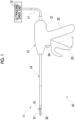
Fig. 1 is an explanatory view showing a configuration of an ultrasonic treatment tool system. -
Figs. 2A and 2B are cross sectional views of main portions of an ultrasonic treatment tool and are cross sectional views of the main portions showing a closed state (Fig. 2A ) and an open state (Fig. 2B ) of a grip part. -
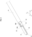
Fig. 3 is a perspective view of the ultrasonic treatment tool in a state where the grip part is closed. -
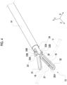
Fig. 4 is a perspective view of the ultrasonic treatment tool in a state where the grip part is open. -
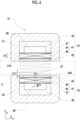
Fig. 5 is a cross sectional view of main portions cut along line V-V ofFig. 2A . -
Fig. 6 is an explanatory view showing a state where treatment is performed on a blood vessel gripped by the grip part. -
Fig. 7 is a perspective view of an edge part of a stress concentration structure. -
Fig. 8 is a block diagram showing an outline of an ultrasonic drive unit. -
Fig. 9 is a graph showing a relationship between a driving time of an ultrasound oscillator and a blood vessel temperature in a case where the blood vessel is gripped and the ultrasound oscillator is driven. -
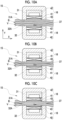
Figs. 10A to 10C are explanatory views showing operations in a case where treatment of sealing the blood vessel is performed with the ultrasonic treatment tool. -
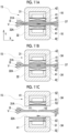
Figs. 11A to 11C are explanatory views showing operations in a case where treatment of incising the blood vessel is performed with the ultrasonic treatment tool. -
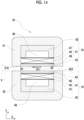
Fig. 12 is a cross sectional view of main portions showing a configuration of a grip part in a second embodiment. -
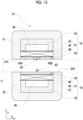
Fig. 13 is an explanatory view showing configurations of a stress concentration structure and a facing member in the second embodiment. -
Fig. 14 is an explanatory view showing some of an operation in a case where treatment of incising a blood vessel is performed in the second embodiment. -
Fig. 15 is a cross sectional view of main portions showing a configuration of a grip part in a modification example. - As shown in
Fig. 1 , an ultrasonictreatment tool system 10 comprises anultrasonic treatment tool 11 and anultrasonic drive unit 12. Theultrasonic treatment tool 11, which is a surgical treatment tool, comprises anoperating part 13, aninsertion part 14, agrip part 15, an ultrasonic oscillator unit 16 (seeFigs. 5 ,6 , and the like), and acable 17. - The
operating part 13 comprises an operating partmain body 21, agrip 22, atrigger 23, and anactivation button 24. The operating partmain body 21 is installed consecutively to a base end part of theinsertion part 14. The operating partmain body 21 is electrically connected to theultrasonic drive unit 12 via thecable 17. Thegrip 22 is provided integrally with the operating partmain body 21 and is held by a user in a case where the user performs a hand technique. - Although details thereof will be described later, the
trigger 23 is provided to be swingable in a direction toward thegrip 22 and a direction separated away from thegrip 22 in order to open and close thegrip part 15. Theactivation button 24 is connected to thecable 17 via a signal cable (not shown) or the like. In a case where theultrasonic drive unit 12 is connected to thecable 17, an activation signal output in response to a pressing operation of theactivation button 24 is input into acontrol unit 55 of theultrasonic drive unit 12 to be described later. - The
insertion part 14 is installed consecutively to a base end part of thegrip part 15. Theinsertion part 14 has a long cylindrical shape and is formed of, for example, a resin. In a case of sealing and incising a biological tissue, theinsertion part 14 is inserted into a body (subject) of a patient, for example, via a trocar. An operation wire 26 (seeFigs. 2A and 2B ) is inserted into theinsertion part 14. Theoperation wire 26 is provided integrally with thegrip part 15. A base end part of theoperation wire 26 is connected to thetrigger 23 inside the operating partmain body 21. For this reason, theoperation wire 26 is operated to be pushed and pulled in an axial direction thereof in theinsertion part 14 in response to swinging of thetrigger 23. Thetrigger 23 is formed in a shape that is easy to operate in each of the direction toward thegrip 22 and the direction separated away from thegrip 22, for example, a shape branched in a Y-shape. - As shown in
Figs. 2A and 2B , thegrip part 15 is provided at a distal end part of theinsertion part 14, that is, a distal end part of theultrasonic treatment tool 11. Thegrip part 15 comprises a pair ofgrip pieces link mechanism 33, and asupport member 34 that supports thegrip pieces support member 34. - The ultrasonic oscillator unit 16 (see
Figs. 5 and6 ) is provided at each of the pair ofgrip pieces ultrasonic oscillator unit 16 is disposed ongrip surfaces grip pieces grip pieces grip part 15 is closed, the grip surfaces 31A and 32A of the pair ofgrip pieces grip pieces - The
ultrasonic oscillator units 16 are in contact with the biological tissue gripped by the pair ofgrip pieces Figs. 5 and6 ) constituting eachultrasonic oscillator unit 16 ultrasonically oscillates with power supplied from theultrasonic drive unit 12 and causes a temperature rise attributable to the device driving (driving of the ultrasound oscillator 41). Accordingly, theultrasonic oscillator units 16 transmit ultrasonic oscillation and heat attributable to the device driving to the biological tissue gripped by the pair ofgrip pieces - In a case where the ultrasound oscillator is disposed at the operating part as in the ultrasonic treatment tool of the related art, a transmitting member having high stiffness needs to be provided between the operating part and the grip part in order to transmit ultrasonic oscillation, and the insertion part also needs to have high stiffness in order to support the transmitting member. On the other hand, in the present invention, since the
ultrasound oscillator 41 is provided at thegrip part 15 as described above, it is sufficient that a signal cable (not shown) for supplying power to theultrasound oscillator 41 is provided between the operatingpart 13 and thegrip part 15, that is, in theinsertion part 14, and theinsertion part 14 does not require high stiffness. That is, as theinsertion part 14, it is possible to select an insertion part made of a material having more flexibility and/or an insertion part with a smaller outer diameter than the ultrasonic treatment tool of the related art, and thereby a degree of freedom in design improves. In addition, it is also possible that theinsertion part 14 comprises a mechanism that deforms theinsertion part 14 from a straight state into a bent state. - The pair of
grip pieces grip part 15 is openable and closable in an up-down direction about asupport shaft 35. Thesupport shaft 35 is supported by thesupport member 34. Thegrip pieces Fig. 3 ) and are formed in the same outer shape. - The
link mechanism 33 comprises alink plate 33A, a connectingpin 33B, and afitting pin 33C. One end part of thelink plate 33A is connected to the pair ofgrip pieces pin 33B. Positions where the pair ofgrip pieces link plate 33A are at base end parts of thegrip pieces support shaft 35. The other end part of thelink plate 33A is connected to a connectingmember 36 provided at a distal end of theoperation wire 26 via thefitting pin 33C. Thefitting pin 33C connects thelink plate 33A to the connectingmember 36 in a rotationally movable manner. - The connecting
member 36 is formed in a cylindrical shape. The connectingmember 36 penetrates through a through-hole 34A formed in thesupport member 34, and a part thereof is positioned inside theinsertion part 14. Thesupport member 34 is formed in a substantially cylindrical shape and is fixed to a distal end of theinsertion part 14. Thesupport member 34 has anotch 34B notched from a distal end thereof. Since the pair ofgrip pieces link plate 33A move inside thenotch 34B, thesupport member 34 does not hinder movement of thegrip pieces link plate 33A. - The
link mechanism 33 converts linear motion caused by a pushing and pulling operation of theoperation wire 26 into rotational motion and operates the pair ofgrip pieces main body 21, a cam mechanism (not shown) or the like that pulls theoperation wire 26 to the base end side in a case where thetrigger 23 is pulled to agrip 22 side and that conversely pushes out theoperation wire 26 to a distal end side in a case where thetrigger 23 is separated away from thegrip 22 is provided. Accordingly, in a case where thetrigger 23 is pulled to thegrip 22 side, thegrip pieces grip part 15 is in a closed state (seeFig. 2A andFig. 3 ), and in a case where thetrigger 23 is separated away from thegrip 22, thegrip pieces grip part 15 is in an open state (seeFig. 2B andFig. 4 ). - A
stress concentration structure 37 is provided at onegrip piece 32, among the pair ofgrip pieces stress concentration structure 37 will be described later. - As shown in
Fig. 5 , theultrasonic oscillator unit 16 is configured by laminating theultrasound oscillator 41, abacking material layer 42, and anacoustic matching layer 43. - The
ultrasound oscillator 41 is composed of a piezoelectric material 44 (also referred to as a piezoelectric element) andelectrodes piezoelectric material 44 is formed in a plate shape. Theelectrodes piezoelectric material 44 and are laminated on both surfaces of thepiezoelectric material 44. Theultrasound oscillator 41 is disposed in parallel with the grip surfaces 31A and 32A of thegrip pieces ultrasound oscillator 41 is disposed at a position facing the biological tissue, such as a blood vessel gripped by thegrip part 15. In addition, a direction in which theultrasound oscillator 41 oscillates is parallel to a direction in which thepiezoelectric material 44 and theelectrodes ultrasound oscillator 41 is parallel to a gripping direction Y in which thegrip part 15 grips. - As the
piezoelectric material 44, lead zirconate titanate (PZT) is preferably used. Thepiezoelectric material 44 is not limited thereto, and it is preferable to use a piezoelectric material having a high Curie point, and a piezoelectric material having a Curie point of 200°C or more, for example, lithium niobate (LiNbO3) or barium titanate (BaTiO3) may be used. The Curie point is also referred to as a Curie temperature, is a temperature at which a crystal structure changes from a tetragonal crystal to a cubic crystal in a case where the temperature of the piezoelectric material is raised, and is a temperature at which the piezoelectric material loses piezoelectricity (can also be referred to as a heat-resistant temperature of the piezoelectric material). - In addition, the
electrodes cable 17 via the signal cable (not shown) or the like. The signal cable is wired, for example, along an inner peripheral surface or an outer peripheral surface of theinsertion part 14. In a case where theultrasonic drive unit 12 is connected to thecable 17, theelectrodes ultrasonic drive unit 12 via thecable 17 or the like. One of theelectrodes cable 17 or the like, and the other is supplied with power of an alternating current voltage signal to be described later from theultrasonic drive unit 12. - The
acoustic matching layer 43 is provided in order to match acoustic impedance between the body of the patient and theultrasound oscillator 41. Theacoustic matching layer 43 is disposed outside theultrasound oscillator 41, and in a strict sense, as shown inFig. 6 , is superimposed on a side facing the biological tissue gripped by thegrip part 15 with respect to theultrasound oscillator 41. That is, theacoustic matching layer 43 is provided at a position exposed from each of the grip surfaces 31A and 32A of thegrip pieces - As the
acoustic matching layer 43 is provided, it is possible to increase light transmittance of ultrasound waves. As a material for theacoustic matching layer 43, various organic materials, in which a value of the acoustic impedance is closer to the value of the body of the patient than thepiezoelectric material 44 of theultrasound oscillator 41, can be used. Specific examples of a material for theacoustic matching layer 43 include an epoxy-based resin, a silicon rubber, polyimide, and polyethylene. In addition, theacoustic matching layer 43 is formed of a plurality of layers, and a material and the number of layers to be composed are selected as appropriate according to the value of the required acoustic impedance. Theultrasonic oscillator unit 16 may have a configuration where theacoustic matching layer 43 is not provided. - The
backing material layer 42 supports theultrasound oscillator 41 from a back side (a side opposite to the acoustic matching layer 43). A backing material is composed of, for example, a material having stiffness or the like, such as hard rubber. In addition, anair gap layer 48, that is, a gap interposed between thebacking material layer 42 and theultrasound oscillator 41 is formed between thebacking material layer 42 and theultrasound oscillator 41. Theair gap layer 48 has a function of reflecting ultrasound waves emitted from the back side of theultrasound oscillator 41 since air inside therein can reflect the ultrasound waves. Accordingly, ultrasonic oscillation can be efficiently transmitted to the biological tissue such as a blood vessel V. The present invention is not limited thereto, and a material that reflects the ultrasound waves may fill thebacking material layer 42, without providing theair gap layer 48. - The
stress concentration structure 37 is a protrusion that protrudes from thegrip surface 32A. As described above, theacoustic matching layer 43 of theultrasonic oscillator unit 16 is provided on thegrip surface 32A. For this reason, thestress concentration structure 37 is fixed to a surface of theacoustic matching layer 43 with, for example, an adhesive. As a method of fixing thestress concentration structure 37 to theacoustic matching layer 43, for example, thestress concentration structure 37 is fixed by applying the adhesive between theacoustic matching layer 43 and thestress concentration structure 37. Alternatively, a groove may be formed in the surface of theacoustic matching layer 43, and thestress concentration structure 37 may be fitted into the groove. Alternatively, thestress concentration structure 37 may be fixed to theacoustic matching layer 43 through both bonding and fitting into the groove. The present invention is not limited thereto, and for example, theacoustic matching layer 43 and thestress concentration structure 37 may be integrally formed of a metal or the like. In addition, a configuration where thestress concentration structure 37 that is positioned at a central portion of thegrip surface 32A and theultrasonic oscillator units 16 that are adjacent to each of the right and left of thestress concentration structure 37 and that pinch thestress concentration structure 37 are further comprised may be adopted. - As shown in
Fig. 7 , thestress concentration structure 37 is a long protrusion disposed along a longitudinal direction of thegrip piece 32, that is, the insertion direction Z. Thestress concentration structure 37 is formed such that adistal end part 37A from thegrip surface 32A in a protruding direction, that is, the gripping direction Y, is in a continuous sawtooth shape. By comprising such astress concentration structure 37, stress is concentrated on a portion of the biological tissue gripped by thegrip part 15, which is in contact with thestress concentration structure 37, and the stress is more likely to be concentrated by making thedistal end part 37A in a sawtooth shape. Accordingly, even in a case where the ultrasonic treatment tool is operated with a smaller force than in a case where the ultrasonic treatment tool of the related art is operated, the blood vessel V or the like, which is the biological tissue, can be incised. In addition, as the continuous sawtooth-shapedstress concentration structure 37 is included, thegrip part 15 can reliably grip the biological tissue. - The
stress concentration structure 37 has hardness of 40 HBW or more in Brinell hardness and is formed of, for example, a metal, ceramics, or the like. Accordingly, stress is more likely to be further transmitted to the biological tissue gripped by thegrip part 15, and thereby treatment of incising the biological tissue can be performed more efficiently. In addition, thestress concentration structure 37 has, for example, a width W11 (a dimension in the width direction X) of 0.2 mm and a height H11 (dimension in the gripping direction Y) that protrudes from thegrip surface 32A of 0.2 mm (seeFig. 6 ). - As shown in
Fig. 8 , theultrasonic drive unit 12 comprises asignal transmitter 51, anamplifier 52, animpedance matching circuit 53, and thecontrol unit 55. Thesignal transmitter 51 has a function of generating an alternating current voltage signal having any frequency and waveform and has, for example, the same configuration and function as a known function generator. - A program related to various types of processing is stored in a program memory (not shown) of the
ultrasonic drive unit 12. Thecontrol unit 55 composed of a processor realizes functions of thesignal transmitter 51, theamplifier 52, and theimpedance matching circuit 53 by executing the program in the program memory. - The
signal transmitter 51 outputs, for example, an alternating current voltage signal having a waveform of a sin wave. In order to supply power to a pair ofultrasound oscillators 41, theamplifier 52 and theimpedance matching circuit 53 are provided for each of theultrasound oscillators 41. Thesignal transmitter 51 outputs each of alternating current voltage signals having the same frequency and the same waveform to theamplifier 52. Theamplifier 52 amplifies the alternating current voltage signal output from thesignal transmitter 51 to a voltage level at which theultrasound oscillator 41 can be driven. Theimpedance matching circuit 53 is connected in series with theamplifier 52 and can match input impedance of the alternating current voltage signal output from theamplifier 52 with impedance of theultrasound oscillator 41. - The
signal transmitter 51 outputs an alternating current voltage signal at a frequency at which a difference from the resonance frequency of thepiezoelectric material 44 is within 20% under the control of thecontrol unit 55. Thepiezoelectric material 44 has a resonance frequency corresponding to a thickness dimension D1 (seeFigs. 5 and6 ), and specifically, in a case where the thickness dimension is defined as D1 (m), the resonance frequency corresponding to the thickness dimension D1 is defined as f (Hz), and the sound speed of the piezoelectric material 44 (the speed of sound waves transmitted through the piezoelectric material 44) is defined as v (m/sec), a relationship of D1 = v/2f is established. - In addition, the
control unit 55 controls thesignal transmitter 51 so that an alternating current voltage signal for driving theultrasound oscillator 41 is continuously supplied. The term "continuously supplied" herein means that the alternating current voltage signal is continuously output from thesignal transmitter 51 without interruption at least during the driving of theultrasound oscillator 41. - In addition, the
control unit 55 receives an activation signal transmitted from theactivation button 24. Thecontrol unit 55 that has received the activation signal controls thesignal transmitter 51 so that an alternating current voltage signal for driving theultrasound oscillator 41 is supplied. -
Fig. 9 is a graph showing ultrasonic oscillation and a temperature rise attributable to the device driving, that is, a relationship between a driving time t of theultrasound oscillator 41 and a blood vessel temperature TE in a case where the blood vessel V is gripped by thegrip pieces ultrasound oscillator 41 is driven. P1 and P2 indicate completion points at which sealing and incision are completed in a case where ultrasonic oscillation and heat attributable to the device driving are transmitted to the blood vessel V, respectively. In addition, t0 is a driving time in a case where theultrasound oscillator 41 starts the ultrasonic oscillation, and t1 and t2 show driving times when the sealing and incision of the blood vessel V are completed, respectively. As shown in the graph, the temperature of the blood vessel V, which is gripped by thegrip part 15 and to which the ultrasonic oscillation and the heat attributable to the device driving are transmitted, rises, and the sealing is completed in a case where the driving time t1 is reached. Further, in a case where the driving time t1 has passed and the driving time t2 is reached, the incision is completed. - An operation in a case where a doctor who is the user performs sealing and incision by the
ultrasonic treatment tool 11 by using the ultrasonictreatment tool system 10 will be described with reference toFigs. 10A to 11C. Figs. 10A to 11C show examples of treating the blood vessel V as the biological tissue. In addition, the reference numeral B indicates blood present in the blood vessel V. Before performing treatment with theultrasonic treatment tool 11, the doctor can puncture the blood vessel V in the patient's body with the trocar at a desired position and depth and insert theultrasonic treatment tool 11 via the trocar, so that thegrip part 15 can reach the blood vessel V. - The doctor swings the
trigger 23 in the direction separated away from thegrip 22 with the finger put thereon while observing an endoscope image captured by an endoscope inserted into the patient's body, for example, from a position different from theultrasonic treatment tool 11, bringing thegrip pieces grip part 15 into an open state. Accordingly, positions of the pair of thegrip pieces Fig. 7 ). - Next, as shown in
Fig. 10A , the doctor swings thetrigger 23 in a direction of pulling to thegrip 22 side so that thegrip pieces grip part 15 grips the blood vessel VFigs. 10A to 10C are explanatory views showing processes in a case where treatment of sealing the blood vessel V is performed. Then, the doctor operates theactivation button 24 to be pressed while maintaining a state where thegrip pieces activation button 24 is input into thecontrol unit 55 of theultrasonic drive unit 12 via thecable 17 or the like. - The
control unit 55 into which an activation signal is input activates each unit of theultrasonic drive unit 12 and controls thesignal transmitter 51 so that an alternating current voltage signal for driving theultrasound oscillator 41 is continuously supplied. Accordingly, the driving of theultrasound oscillator 41 is started, and ultrasonic oscillation is transmitted to the blood vessel V. -
Fig. 10B is a state immediately after ultrasonic oscillation of theultrasound oscillator 41 is started to be transmitted to the blood vessel V while a state where thegrip pieces grip pieces grip part 15 comprises thestress concentration structure 37, in a case where thegrip pieces stress concentration structure 37 can reliably grip the blood vessel V by biting into the blood vessel V. That is, treatment of sealing the blood vessel V can be efficiently performed. - Then, as shown in
Fig. 10C , the temperature of the blood vessel V rises by transmitting ultrasonic oscillation of theultrasound oscillator 41 while a state where thegrip pieces ultrasound oscillator 41 is driven at a frequency at which a difference from the resonance frequency described above is within 20%, the temperature of the blood vessel V reaches 150°C or more within 5 seconds. In this case, both heat generation of theultrasound oscillator 41 itself and heat generation caused by ultrasonic oscillation raise the temperature of the blood vessel V. - In a case where the blood vessel V has reached a certain temperature (approximately 60°C to 90°C) or more, components such as proteins are coagulated. For this reason, a portion of the blood vessel V, which is gripped by the
grip pieces - In a case where treatment of the blood vessel V is performed under the conditions described above, the blood vessel V is completely sealed at the driving time t1 = 5 seconds and is completely incised at the driving time t2 = 10 seconds (see
Fig. 9 ). Accordingly, in a case where treatment of sealing the blood vessel V is performed, it is preferable that the treatment is terminated in 5 seconds or more and less than 10 seconds after ultrasonic oscillation of theultrasound oscillator 41 is started to be transmitted. - On the other hand, in a case where treatment of incising the blood vessel V is performed, the doctor grips the blood vessel V by operating the
ultrasonic treatment tool 11 as in a case where treatment of sealing the blood vessel V is performed (seeFig. 11A). Figs. 11A to 11C are explanatory views showing processes in a case where treatment of incising the blood vessel V is performed. Then, the doctor operates theactivation button 24 to be pressed while maintaining a state where thegrip pieces activation button 24 is input into thecontrol unit 55 of theultrasonic drive unit 12. - The
control unit 55 into which an activation signal is input activates each unit of theultrasonic drive unit 12 and controls thesignal transmitter 51 so that an alternating current voltage signal is continuously supplied. Accordingly, the driving of theultrasound oscillator 41 is started, and ultrasonic oscillation is transmitted to the blood vessel V. The doctor increases a gripping pressure at which the blood vessel V is gripped by further swinging thetrigger 23 in the direction of pulling to thegrip 22 side. In this case, the gripping pressure is larger than a case of performing treatment of sealing the blood vessel V. - As shown in
Fig. 11B , in a case where the temperature of the blood vessel V rises as ultrasonic oscillation of theultrasound oscillator 41 and heat attributable to the device driving are transmitted, and a gripping pressure of thegrip part 15 further increases, stress is concentrated on the portion of the blood vessel V, which is in contact with thestress concentration structure 37. In addition, in this case, the blood vessel V has decreased mechanical strength due to the temperature rise. Since thestress concentration structure 37 is a protrusion that protrudes from thegrip surface 32A, the portion of the blood vessel V, which is in contact with thestress concentration structure 37, has a smaller thickness than a portion in contact with thegrip surface 32A. Further, as thedistal end part 37A has a sawtooth shape, stress is likely to be concentrated. Accordingly, the blood vessel V can be easily incised even in a case where theultrasonic treatment tool 11 is operated with a smaller force than in a case of operating the ultrasonic treatment tool of the related art. That is, treatment of incising the blood vessel V can be efficiently performed. - In a case where the blood vessel V is treated under the conditions described above, the blood vessel V is completely incised at the driving time t2 = 7 seconds. Accordingly, in a case where treatment of incising the blood vessel V is performed, it is preferable that the treatment is terminated after 7 seconds or more from the start of transmission of ultrasonic oscillation of the
ultrasound oscillator 41. - After the driving time t2 when the incision is completed has passed, as shown in
Fig. 11C , the doctor swings thetrigger 23 in the direction separated away from thegrip 22, bringing thegrip pieces grip part 15 into an open state. Incised portions V1 and V2 of the blood vessel V are separated from each other and are separated from thegrip pieces - As shown in
Figs. 12 to 14 , in addition to the configuration of the first embodiment, a surface facing the stress concentration structure may comprise a member having the same hardness as the stress concentration structure. In this case, it is preferable that agrip part 61 comprises astress concentration structure 62 at onegrip piece 32 of the pair ofgrip pieces member 63 that has the same hardness as thestress concentration structure 62 at theother grip piece 31. Hereinafter, the same components as thegrip part 15 in the first embodiment will be assigned with the same reference numerals, and description thereof will be omitted. In addition, the configuration is the same as that of theultrasonic treatment tool 11 of the first embodiment, except that the configuration of thegrip part 15 is replaced with the configuration of thegrip part 61, and description thereof will be omitted. - As shown in
Fig. 12 , thestress concentration structure 62 is a protrusion that protrudes from thegrip surface 32A and is fixed to the surface of theacoustic matching layer 43, like thestress concentration structure 37 in the first embodiment. In addition, thestress concentration structure 62 has hardness of 40 HBW or more in Brinell hardness and is formed of, for example, a metal, ceramics, or the like. A method of fixing thestress concentration structure 62 to theacoustic matching layer 43 is the same as the method of fixing thestress concentration structure 37 to theacoustic matching layer 43 in the first embodiment. The present invention is not limited thereto, and for example, theacoustic matching layer 43 and thestress concentration structure 62 may be integrally formed of a metal or the like. - The
stress concentration structure 62 is a long protrusion disposed along the longitudinal direction of thegrip piece 32, that is, the insertion direction Z. Thestress concentration structure 62 is formed such that adistal end part 62A from thegrip surface 32A in the protruding direction, that is, the gripping direction Y, is in a continuous sawtooth shape, like thestress concentration structure 37 in the first embodiment. - The facing
member 63 is a plate-shaped member disposed at a position facing thestress concentration structure 62. The facingmember 63 is formed in a long shape disposed along a longitudinal direction of thegrip piece 31. The facingmember 63 is at thegrip surface 31A of thegrip piece 31 and is fixed to the surface of theacoustic matching layer 43. The facingmember 63 has the same hardness as thestress concentration structure 62 as described above, and specifically, a surface facing thestress concentration structure 62 has hardness of 40 HBW or more in Brinell hardness and is formed of, for example, metal, ceramics, or the like. - As shown in
Fig. 13 , a width W22 (a dimension in the width direction X) of the facingmember 63 is larger than a width W21 of thestress concentration structure 62. For example, the width W22 of the facingmember 63 is 0.6 mm, and the width W21 of thestress concentration structure 62 is 0.2 mm. Accordingly, in a case where thegrip part 15 is closed, thestress concentration structure 62 and the facingmember 63 can be reliably faced with each other. - An operation in a case where the doctor who is the user performs incision treatment with the ultrasonic treatment tool according to the present embodiment will be described with reference to
Figs. 12 to 14 . The operation in a case of performing sealing treatment with the ultrasonic treatment tool of the present embodiment is the same as in the first embodiment, and description thereof will be omitted. - In a case where treatment of incising the blood vessel V is performed, the doctor grips the blood vessel V by operating the
ultrasonic treatment tool 11, as in the case of the first embodiment (a state shown inFig. 12 ). Then, the doctor operates theactivation button 24 to be pressed while maintaining a state where thegrip pieces activation button 24 is input into thecontrol unit 55. - The
control unit 55 into which an activation signal is input controls thesignal transmitter 51 so that an alternating current voltage signal is continuously supplied. Accordingly, the driving of theultrasound oscillator 41 is started, and ultrasonic oscillation is transmitted to the blood vessel V. The doctor increases a gripping pressure at which the blood vessel V is gripped by further swinging thetrigger 23 in the direction of pulling to thegrip 22 side. - As shown in
Fig. 14 , in a case where the temperature of the blood vessel V rises as ultrasonic oscillation of theultrasound oscillator 41 is transmitted, and a gripping pressure of thegrip part 61 further increases, stress is concentrated on a portion of the blood vessel V, which is in contact with thestress concentration structure 62. In the present embodiment, the facingmember 63 having the same hardness is provided at a position facing the stress concentration structure 62 (seeFig. 13 ). Since the blood vessel V is in a state of being pinched between thestress concentration structure 62 and the facingmember 63, stress is not dispersed. Accordingly, the stress is more likely to be concentrated on the portion of the blood vessel V gripped by thegrip part 61, which is in contact with thestress concentration structure 62. Accordingly, the blood vessel V can be easily incised even in a case where theultrasonic treatment tool 11 is operated with a force smaller than in the first embodiment. That is, treatment of incising the blood vessel V can be efficiently performed. - The facing
member 63 comprised in theother grip piece 31 is configured to be fixed to theultrasonic oscillator unit 16 in the second embodiment, but without being limited thereto, may constitute a part of theultrasonic oscillator unit 16. In a modification example shown inFig. 15 , for example, a part of theacoustic matching layer 43 constituting thegrip surface 31A in theultrasonic oscillator unit 16 is defined as the facingmember 63 and is made of a material having the same hardness as thestress concentration structure 62. In this case, since the facingmember 63 is disposed at the center of theacoustic matching layer 43, a part excluding the facingmember 63 is divided into twoacoustic matching layers acoustic matching layers acoustic matching layers member 63 are fixed to each other and are disposed on thegrip surface 31A. - Although treatment of gripping the blood vessel as the biological tissue and sealing and incising the blood vessel has been described as an example in each of the embodiments, the biological tissue to be treated is not limited to the blood vessel, and can also be applied to a tubular biological tissue, for example, a part of the intestine, a part of the reproductive system, or the like.
- Although the
ultrasound oscillator 41 is comprised in both the pair ofgrip pieces grip part 15, and ultrasonic oscillation is transmitted to the structure from both thegrip pieces ultrasound oscillator 41 may be provided at only one of the pair ofgrip pieces grip part 15. In this case, it is preferable that theultrasound oscillator 41 is disposed at one grip piece, and the grip surface of the other grip piece facing theultrasound oscillator 41 is formed of a material that reflects ultrasonic oscillation caused by theultrasound oscillator 41. In addition, in this case, it is preferable that the stress concentration structure described in each of the embodiments described above is provided at one of the pair ofgrip pieces ultrasound oscillator 41 is disposed. -
- 10: ultrasonic treatment tool system
- 11: ultrasonic treatment tool
- 12: ultrasonic drive unit
- 13: operating part
- 14: insertion part
- 15: grip part
- 16: ultrasonic oscillator unit
- 17: cable
- 21: operating part main body
- 22: grip
- 23: trigger
- 24: activation button
- 26: operation wire
- 31, 32: grip piece
- 31A, 32A: grip surface
- 33: link mechanism
- 33A: link plate
- 33B: connecting pin
- 33C: fitting pin
- 34: support member
- 34A: through-hole
- 34B: notch
- 35: support shaft
- 36: connecting member
- 37: stress concentration structure
- 37A: distal end part
- 41: ultrasound oscillator
- 42: backing material layer
- 43: acoustic matching layer
- 43A, 43B: acoustic matching layer
- 44: piezoelectric material
- 46, 47: electrode
- 48: air gap layer
- 51: signal transmitter
- 52: amplifier
- 53: impedance matching circuit
- 55: control unit
- 61: grip part
- 62: stress concentration structure
- 62A: distal end part
- 63: facing member
- B: blood
- D1: thickness dimension
- H11: height
- t, t0, 11, t2: driving time
- TE: temperature
- V: blood vessel
- V1, V2: incised portion
- W11: width
- W21: width
- W22: width
Claims (11)
- An ultrasonic treatment tool comprising:a grip part that is provided at a distal end part and that grips a biological tissue in a subj ect;an ultrasound oscillator that transmits ultrasonic oscillation to the biological tissue gripped by the grip part; anda stress concentration structure that is provided at the grip part and that protrudes from a grip surface facing the biological tissue,wherein the stress concentration structure is a long protrusion disposed along a longitudinal direction of the grip part, anda distal end part from the grip surface in a protruding direction is formed in a continuous sawtooth shape.
- The ultrasonic treatment tool according to claim 1,
wherein the ultrasound oscillator is disposed at the grip part. - The ultrasonic treatment tool according to claim 1 or 2,
wherein the stress concentration structure has hardness of 40 HBW or more in Brinell hardness. - The ultrasonic treatment tool according to claim 3,
wherein a surface of the grip part, which faces the stress concentration structure, has hardness of 40 HBW or more in Brinell hardness. - The ultrasonic treatment tool according to any one of claims 1 to 4,
wherein the ultrasound oscillator is composed of a piezoelectric material and is driven by an alternating current voltage signal having a frequency at which a difference from a resonance frequency corresponding to a thickness dimension of the piezoelectric material is within 20%. - The ultrasonic treatment tool according to claim 5,
wherein the piezoelectric material is lead zirconate titanate. - The ultrasonic treatment tool according to claim 5,
wherein a Curie point of the piezoelectric material is 200°C or more. - The ultrasonic treatment tool according to any one of claims 1 to 7,
wherein an alternating current voltage signal for driving the ultrasound oscillator is continuously supplied. - The ultrasonic treatment tool according to any one of claims 1 to 8,
wherein the grip part grips a blood vessel which is the biological tissue. - The ultrasonic treatment tool according to any one of claims 1 to 9, which is a surgical treatment tool comprising an insertion part that is installed consecutively to a base end of the grip part and an operating part that is installed consecutively to a base end of the insertion part.
- The ultrasonic treatment tool according to any one of claims 1 to 10,
wherein the grip part comprises a pair of grip pieces that grips the biological tissue, and the stress concentration structure is provided at one grip piece.
Applications Claiming Priority (2)
| Application Number | Priority Date | Filing Date | Title |
|---|---|---|---|
| JP2022020291 | 2022-02-14 | ||
| PCT/JP2023/003798 WO2023153363A1 (en) | 2022-02-14 | 2023-02-06 | Ultrasonic treatment tool |
Publications (2)
| Publication Number | Publication Date |
|---|---|
| EP4480425A1 true EP4480425A1 (en) | 2024-12-25 |
| EP4480425A4 EP4480425A4 (en) | 2025-05-14 |
Family
ID=87564328
Family Applications (1)
| Application Number | Title | Priority Date | Filing Date |
|---|---|---|---|
| EP23752827.8A Pending EP4480425A4 (en) | 2022-02-14 | 2023-02-06 | ULTRASOUND TREATMENT TOOL |
Country Status (5)
| Country | Link |
|---|---|
| US (1) | US20240398438A1 (en) |
| EP (1) | EP4480425A4 (en) |
| JP (1) | JPWO2023153363A1 (en) |
| CN (1) | CN118871046A (en) |
| WO (1) | WO2023153363A1 (en) |
Family Cites Families (14)
| Publication number | Priority date | Publication date | Assignee | Title |
|---|---|---|---|---|
| US6129735A (en) * | 1996-06-21 | 2000-10-10 | Olympus Optical Co., Ltd. | Ultrasonic treatment appliance |
| US5873873A (en) * | 1997-10-10 | 1999-02-23 | Ethicon Endo-Surgery, Inc. | Ultrasonic clamp coagulator apparatus having improved clamp mechanism |
| US6569178B1 (en) * | 1999-03-09 | 2003-05-27 | Olympus Optical Co., Ltd. | Ultrasonic coagulating/cutting apparatus |
| US6325811B1 (en) * | 1999-10-05 | 2001-12-04 | Ethicon Endo-Surgery, Inc. | Blades with functional balance asymmetries for use with ultrasonic surgical instruments |
| JP2001332125A (en) * | 2000-05-23 | 2001-11-30 | Ricoh Co Ltd | Composite ferroelectric thick film, composite ferroelectric thick film forming method, and capacitor and pyroelectric element using the composite ferroelectric thick film |
| CA2466031C (en) * | 2001-11-07 | 2012-04-10 | Ethicon Endo-Surgery, Inc. | An ultrasonic clamp coagulator apparatus having an improved clamping end-effector |
| JP2006158525A (en) * | 2004-12-03 | 2006-06-22 | Olympus Medical Systems Corp | Ultrasonic surgical apparatus and driving method of ultrasonic treatment instrument |
| JP2006340857A (en) * | 2005-06-08 | 2006-12-21 | Feather Safety Razor Co Ltd | Surgical scalpel |
| US20100063526A1 (en) * | 2008-09-05 | 2010-03-11 | Jean Michael Beaupre | Jaw |
| US20140005702A1 (en) * | 2012-06-29 | 2014-01-02 | Ethicon Endo-Surgery, Inc. | Ultrasonic surgical instruments with distally positioned transducers |
| US9241728B2 (en) | 2013-03-15 | 2016-01-26 | Ethicon Endo-Surgery, Inc. | Surgical instrument with multiple clamping mechanisms |
| JP6184253B2 (en) * | 2013-08-28 | 2017-08-23 | オリンパス株式会社 | Surgical treatment device and surgical treatment system |
| US20170258487A1 (en) * | 2016-03-10 | 2017-09-14 | Olympus Corporation | Surgical treatment instrument and surgical treatment instrument apparatus |
| WO2017191683A1 (en) * | 2016-05-06 | 2017-11-09 | オリンパス株式会社 | Ultrasonic medical device, energy treatment tool, and control device |
-
2023
- 2023-02-06 CN CN202380021840.3A patent/CN118871046A/en active Pending
- 2023-02-06 JP JP2023580239A patent/JPWO2023153363A1/ja active Pending
- 2023-02-06 WO PCT/JP2023/003798 patent/WO2023153363A1/en not_active Ceased
- 2023-02-06 EP EP23752827.8A patent/EP4480425A4/en active Pending
-
2024
- 2024-08-13 US US18/803,716 patent/US20240398438A1/en active Pending
Also Published As
| Publication number | Publication date |
|---|---|
| WO2023153363A1 (en) | 2023-08-17 |
| EP4480425A4 (en) | 2025-05-14 |
| CN118871046A (en) | 2024-10-29 |
| US20240398438A1 (en) | 2024-12-05 |
| JPWO2023153363A1 (en) | 2023-08-17 |
Similar Documents
| Publication | Publication Date | Title |
|---|---|---|
| US20230380857A1 (en) | Ultrasonic surgical shears and method for sealing a blood vessel using same | |
| US9352173B2 (en) | Treatment device | |
| JP6878442B2 (en) | Surgical instruments that apply electrosurgical energy and ultrasonic energy in stages | |
| US8388647B2 (en) | Apparatus for tissue sealing | |
| US20030212332A1 (en) | Disposable ultrasonic soft tissue cutting and coagulation systems | |
| US20030212331A1 (en) | Ultrasonic soft tissue cutting and coagulation systems having multiple superposed vibrational modes | |
| US20190046226A1 (en) | Ultrasound medical apparatus, energy treatment instrument and control apparatus | |
| US20190008548A1 (en) | Ultrasound medical device | |
| EP4480425A1 (en) | Ultrasonic treatment tool | |
| CN100522086C (en) | Ultrasonic wave disposal apparatus | |
| US20250221729A1 (en) | Surgical treatment device | |
| JP3766520B2 (en) | Vascular anastomosis device | |
| JPH0723970A (en) | Ultrasonic treatment apparatus | |
| JPWO2022172693A5 (en) | ||
| US20230240701A1 (en) | Ultrasonic treatment tool and endoscope system | |
| WO2024247993A1 (en) | Surgical treatment device | |
| JPH0723974A (en) | Ultrasonic treatment apparatus | |
| EP4501256A1 (en) | Surgical treatment device | |
| JP3679747B2 (en) | Ultrasonic treatment device | |
| JP2001037771A (en) | Ultrasonic treatment device | |
| JPH0723972A (en) | Ultrasonic treatment apparatus |
Legal Events
| Date | Code | Title | Description |
|---|---|---|---|
| STAA | Information on the status of an ep patent application or granted ep patent |
Free format text: STATUS: THE INTERNATIONAL PUBLICATION HAS BEEN MADE |
|
| PUAI | Public reference made under article 153(3) epc to a published international application that has entered the european phase |
Free format text: ORIGINAL CODE: 0009012 |
|
| STAA | Information on the status of an ep patent application or granted ep patent |
Free format text: STATUS: REQUEST FOR EXAMINATION WAS MADE |
|
| 17P | Request for examination filed |
Effective date: 20240814 |
|
| AK | Designated contracting states |
Kind code of ref document: A1 Designated state(s): AL AT BE BG CH CY CZ DE DK EE ES FI FR GB GR HR HU IE IS IT LI LT LU LV MC ME MK MT NL NO PL PT RO RS SE SI SK SM TR |
|
| A4 | Supplementary search report drawn up and despatched |
Effective date: 20250414 |
|
| RIC1 | Information provided on ipc code assigned before grant |
Ipc: A61B 17/32 20060101ALI20250409BHEP Ipc: A61B 17/00 20060101AFI20250409BHEP |
|
| DAV | Request for validation of the european patent (deleted) | ||
| DAX | Request for extension of the european patent (deleted) |