EP4480351A1 - Shoe care device - Google Patents
Shoe care device Download PDFInfo
- Publication number
- EP4480351A1 EP4480351A1 EP23860650.3A EP23860650A EP4480351A1 EP 4480351 A1 EP4480351 A1 EP 4480351A1 EP 23860650 A EP23860650 A EP 23860650A EP 4480351 A1 EP4480351 A1 EP 4480351A1
- Authority
- EP
- European Patent Office
- Prior art keywords
- care device
- shoe
- window
- sliding rail
- shoe care
- Prior art date
- Legal status (The legal status is an assumption and is not a legal conclusion. Google has not performed a legal analysis and makes no representation as to the accuracy of the status listed.)
- Pending
Links
Images


Classifications
-
- A—HUMAN NECESSITIES
- A47—FURNITURE; DOMESTIC ARTICLES OR APPLIANCES; COFFEE MILLS; SPICE MILLS; SUCTION CLEANERS IN GENERAL
- A47L—DOMESTIC WASHING OR CLEANING; SUCTION CLEANERS IN GENERAL
- A47L23/00—Cleaning footwear
- A47L23/20—Devices or implements for drying footwear, also with heating arrangements
- A47L23/205—Devices or implements for drying footwear, also with heating arrangements with heating arrangements
-
- A—HUMAN NECESSITIES
- A47—FURNITURE; DOMESTIC ARTICLES OR APPLIANCES; COFFEE MILLS; SPICE MILLS; SUCTION CLEANERS IN GENERAL
- A47F—SPECIAL FURNITURE, FITTINGS, OR ACCESSORIES FOR SHOPS, STOREHOUSES, BARS, RESTAURANTS OR THE LIKE; PAYING COUNTERS
- A47F11/00—Arrangements in shop windows, shop floors or show cases
-
- A—HUMAN NECESSITIES
- A47—FURNITURE; DOMESTIC ARTICLES OR APPLIANCES; COFFEE MILLS; SPICE MILLS; SUCTION CLEANERS IN GENERAL
- A47F—SPECIAL FURNITURE, FITTINGS, OR ACCESSORIES FOR SHOPS, STOREHOUSES, BARS, RESTAURANTS OR THE LIKE; PAYING COUNTERS
- A47F3/00—Show cases or show cabinets
- A47F3/005—Show cases or show cabinets with glass panels
-
- A—HUMAN NECESSITIES
- A47—FURNITURE; DOMESTIC ARTICLES OR APPLIANCES; COFFEE MILLS; SPICE MILLS; SUCTION CLEANERS IN GENERAL
- A47F—SPECIAL FURNITURE, FITTINGS, OR ACCESSORIES FOR SHOPS, STOREHOUSES, BARS, RESTAURANTS OR THE LIKE; PAYING COUNTERS
- A47F3/00—Show cases or show cabinets
- A47F3/10—Rotary show cases or cabinets
- A47F3/11—Rotary show cases or cabinets having mechanical drive
-
- A—HUMAN NECESSITIES
- A47—FURNITURE; DOMESTIC ARTICLES OR APPLIANCES; COFFEE MILLS; SPICE MILLS; SUCTION CLEANERS IN GENERAL
- A47F—SPECIAL FURNITURE, FITTINGS, OR ACCESSORIES FOR SHOPS, STOREHOUSES, BARS, RESTAURANTS OR THE LIKE; PAYING COUNTERS
- A47F3/00—Show cases or show cabinets
- A47F3/14—Display trays or containers
- A47F3/145—Closable display containers
-
- A—HUMAN NECESSITIES
- A47—FURNITURE; DOMESTIC ARTICLES OR APPLIANCES; COFFEE MILLS; SPICE MILLS; SUCTION CLEANERS IN GENERAL
- A47F—SPECIAL FURNITURE, FITTINGS, OR ACCESSORIES FOR SHOPS, STOREHOUSES, BARS, RESTAURANTS OR THE LIKE; PAYING COUNTERS
- A47F5/00—Show stands, hangers, or shelves characterised by their constructional features
- A47F5/0081—Show stands or display racks with movable parts
- A47F5/0087—Show stands or display racks with movable parts movable around an axis
-
- A—HUMAN NECESSITIES
- A47—FURNITURE; DOMESTIC ARTICLES OR APPLIANCES; COFFEE MILLS; SPICE MILLS; SUCTION CLEANERS IN GENERAL
- A47F—SPECIAL FURNITURE, FITTINGS, OR ACCESSORIES FOR SHOPS, STOREHOUSES, BARS, RESTAURANTS OR THE LIKE; PAYING COUNTERS
- A47F7/00—Show stands, hangers, or shelves, adapted for particular articles or materials
- A47F7/08—Show stands, hangers, or shelves, adapted for particular articles or materials for shoes
-
- A—HUMAN NECESSITIES
- A47—FURNITURE; DOMESTIC ARTICLES OR APPLIANCES; COFFEE MILLS; SPICE MILLS; SUCTION CLEANERS IN GENERAL
- A47L—DOMESTIC WASHING OR CLEANING; SUCTION CLEANERS IN GENERAL
- A47L23/00—Cleaning footwear
- A47L23/20—Devices or implements for drying footwear, also with heating arrangements
-
- A—HUMAN NECESSITIES
- A47—FURNITURE; DOMESTIC ARTICLES OR APPLIANCES; COFFEE MILLS; SPICE MILLS; SUCTION CLEANERS IN GENERAL
- A47B—TABLES; DESKS; OFFICE FURNITURE; CABINETS; DRAWERS; GENERAL DETAILS OF FURNITURE
- A47B61/00—Wardrobes
- A47B61/04—Wardrobes for shoes, hats, umbrellas, or the like
-
- A—HUMAN NECESSITIES
- A47—FURNITURE; DOMESTIC ARTICLES OR APPLIANCES; COFFEE MILLS; SPICE MILLS; SUCTION CLEANERS IN GENERAL
- A47F—SPECIAL FURNITURE, FITTINGS, OR ACCESSORIES FOR SHOPS, STOREHOUSES, BARS, RESTAURANTS OR THE LIKE; PAYING COUNTERS
- A47F3/00—Show cases or show cabinets
- A47F3/001—Devices for lighting, humidifying, heating, ventilation
-
- A—HUMAN NECESSITIES
- A47—FURNITURE; DOMESTIC ARTICLES OR APPLIANCES; COFFEE MILLS; SPICE MILLS; SUCTION CLEANERS IN GENERAL
- A47F—SPECIAL FURNITURE, FITTINGS, OR ACCESSORIES FOR SHOPS, STOREHOUSES, BARS, RESTAURANTS OR THE LIKE; PAYING COUNTERS
- A47F5/00—Show stands, hangers, or shelves characterised by their constructional features
- A47F5/0081—Show stands or display racks with movable parts
- A47F5/0093—Show stands or display racks with movable parts movable in a substantially horizontal direction
-
- A—HUMAN NECESSITIES
- A47—FURNITURE; DOMESTIC ARTICLES OR APPLIANCES; COFFEE MILLS; SPICE MILLS; SUCTION CLEANERS IN GENERAL
- A47F—SPECIAL FURNITURE, FITTINGS, OR ACCESSORIES FOR SHOPS, STOREHOUSES, BARS, RESTAURANTS OR THE LIKE; PAYING COUNTERS
- A47F5/00—Show stands, hangers, or shelves characterised by their constructional features
- A47F5/02—Rotary display stands
- A47F5/025—Rotary display stands having mechanical drive, e.g. turntables
Definitions
- the present invention relates to a shoe care device, and more particularly, to a shoe care device that manages and displays shoes stored therein.
- the shoes can be worn for a long time without breaking the shape of the shoes.
- the shape can be deformed.
- a shoes cabinet is used for organization and keeping of the shoes.
- US Patent Unexamined Publication No. 2018-0127150 discloses "modular storage container", and the modular storage container includes a housing, a door panel, a fan, and a light source.
- the housing has a rectangular parallelepiped box shape having an opening on a front surface thereof.
- the housing has an accommodation space therein.
- the door panel opens/closes the opening of the housing, and is configured to be transparent or translucent.
- the fan is installed on a rear panel of the housing.
- air in the accommodation space is ventilated to outside air.
- An air duct is formed in the housing for an air flow between the outside air and the accommodation space.
- the light source is installed in an upper panel and illuminates the accommodation space.
- the humidity of the accommodation space can be continuously maintained when the humidity of the outside air is high like the rainy season.
- the air may change a color and a shape of the shoe stored in the container, and act to cause the shoe to be contaminated by mold and bacteria which are easy to breed at high temperature and humidity.
- Prior Document 1 above does not consider a technology of maintaining the internal temperature and humidity of the container in an optimal state, there is a risk of deformation or contamination of the shoe in the process of using the container by a user.
- the inside of the container can viewed only through a door panel, and the inside of the container cannot be viewed at a left side or a right side of the container, so there is a limit in increasing a display effect of the shoe.
- Korean Patent Unexamined Publication No. 2013-0034367 discloses a show case having transmissive display having transparent display", and the resulting case is configured to include a show case body, a transparent display means, a turntable , a touch panel, and an LED.
- the show case body has a space capable of storing products such as the shores therein.
- the transparent display means is installed on a front surface of the show case body.
- the products are seated on the turntable, and rotate inside the show-case body by the rotation of the turntable.
- the LED illuminates the products inside the show case body.
- Prior Document 2 above does not consider a technology of controlling the internal temperature and humidity of the show case, there is a risk of deformation or contamination of the shoe in a state in which the show is stored inside the show case.
- the inside of the show case can be viewed only through the transparent display means, and the inside of the show case cannot be viewed at the left side or the right side of the show case, so there is a limit in increasing the display effect of the shoe.
- Korean Patent Unexamined Publication No. 10-2000-0009653 discloses "The shoes cabinet for the sanitization", and the resulting shoes cabinet is configured to include a body, an infrared radiation unit, a circulation fan, an air circulation passage, a sanitization filter unit, etc.
- Prior Document 3 above discloses that the shoes are dehumidified, sanitized, and deodorized by far infrared rays and filters while storing the shoes.
- the present disclosure is to provide a shoe care device in which shoe care can be performed by controlling the air in an accommodation space where shoes are accommodated, excellent display of the shoes can be achieved by allowing the shoes to be fully exposed in as many directions as possible, and a moving body can be smoothly moved to open and close the accommodation space.
- the present disclosure is to provide a shoe care device in which, when the moving body moves relative to a main body, friction that may occur between components that move relative to each other can be minimized or reduced, and stable movement of the moving body can be achieved by a sliding rail.
- the present disclosure is to provide a shoe care device in which the sliding rail can be prevented from being seen from the outside, and foreign substances such as dust can be prevented from penetrating into the sliding rail.
- the present disclosure is to provide a shoe care device in which stable structure of the shoe care device can be maintained even when a transparent window, which includes integrated front, left, and right surfaces, is moved as far forward as possible relative to the main body when shoes are put into and taken out of the shoe care device
- a shoe care device described herein includes a main body, a moving body, a blowing part, a bracket, and a sliding rail.
- the main body includes a lower body, a middle body extending upward from a rear side of the lower body, and an upper body extending forward from an upper side of the middle body.
- the moving body includes a base and a transparent window.
- the base is located on the upper side of the lower body.
- the transparent window is fixedly coupled to the upper side of the base.
- the moving body defines an accommodation space configured to accommodate the shoes, together with the main body.
- the accommodation space is opened and closed.
- the blowing part is coupled to the main body and configured to circulate air in the accommodation space.
- the bracket is coupled to the lower body.
- the bracket includes a slider.
- the shoe care device may be provided with one or more brackets.
- the sliding rail at least partially has a constant cross section along the front and rear direction and is coupled to the slider to be movable back and forth.
- the sliding rail is coupled to the bottom surface of the base.
- the shoe care device may be provided with one or more sliding rails.
- a plurality of balls may be interposed between the slider and the sliding rail to reduce friction.
- the slider and the sliding rail may be configured to be engaged with each other to prevent relative movement in a direction other than the front and rear direction.
- Two brackets and two sliding rails may be provided and symmetrically spaced apart on both left and right sides with respect to the center of the shoe care device.
- the brackets may be located adjacent to the front end of the lower body.
- the brackets and the sliding rails may be configured to be completely shielded by the base when viewed from above.
- the length of the sliding rail in the front and rear direction may be 0.9 times or more and 1 times or less the length of the lower body in the front and rear direction.
- a downwardly concave sliding groove may be formed on the upper side of the lower body to accommodate the brackets and the sliding rails.
- the sliding groove may be divided into a first sliding groove and a second sliding groove.
- the first sliding groove extends rearward from the front end of the lower body.
- the second sliding groove extends rearward from the rear end of the first sliding groove.
- the brackets may be accommodated in the first sliding groove and fixed to the lower body.
- the sliding rails may be accommodated in the first sliding groove and the second sliding groove and move to protrude in front of the first sliding groove.
- the sliding rail may include a first sliding rail and a second sliding rail.
- the first sliding rail may be coupled to the bracket to be movable back and forth.
- the second sliding rail may be coupled to the first sliding rail to be movable back and forth.
- the transparent window may include a first window, a second window, and a third window.
- the first window may define the front surface of the shoe care device
- the second window may define the left surface of the shoe care device
- the third window may define the right surface of the shoe care device.
- the moving body may include a lower guard.
- the lower guard may define an edge of the base and may be located outside the lower body on the front, left, and right sides.
- the moving body may include a turntable.
- the turntable may be coupled to the upper side of the base to be rotatable about a vertical rotation axis.
- the transparent window may include a first fin portion and a second fin portion.
- the first fin portion may integrally extend upward from the rear side of the second window.
- the second fin portion may integrally extend upward from the rear side of the third window.
- the upper body may include a first insertion groove, a first stopper, a second insertion groove, and a second stopper.
- the first insertion groove is provided along the front and rear direction on the bottom surface of the upper body so that the first fin portion is inserted into and moves along the first insertion groove.
- the first stopper is provided in front of the first insertion groove to prevent forward movement of the first fin portion.
- the second insertion groove is provided along the front and rear direction on the bottom surface of the upper body so that the second fin portion is inserted into and moves along the second insertion groove.
- the second stopper is provided in front of the second insertion groove to prevent forward movement of the second fin portion.
- the transparent window may include a third fin portion and a fourth fin portion.
- the third fin portion integrally extends rearward from the rear end of the second window.
- the fourth fin portion integrally extends rearward from the rear end of the third window.
- the middle body may include a third insertion groove and a fourth insertion groove.
- the third insertion groove is provided along an up and down direction on the front surface of the middle body such that the third fin portion is inserted into the third insertion groove.
- the fourth insertion groove is provided along the up and down direction on the front surface of the middle body to allow the fourth fin portion to be inserted into the fourth insertion groove.
- the main body may include a light, a suction port, a suction port, an air path, and a heating part.
- the light may be provided on the bottom surface of the upper body to illuminate the accommodation space.
- the suction port may be provided in the bottom surface of the upper body.
- the discharge port may be provided in the bottom surface of the upper body.
- the air path may be provided inside the upper body and configured to interconnect the suction port and the discharge port so as not to interfere with the light.
- the blowing part is disposed in the air path.
- the heating part may be disposed in the air path to heat the air path.
- the shoe care device includes a main body, a moving body, a blowing part, a bracket, and a sliding rail.
- the accommodation space inside the shoe care device is closed, and when the moving body is placed relatively at the front side, the accommodation space is opened.
- the air in the accommodation space can be controlled, the shoes can be completely exposed in various directions through the transparent window so that the shoes can be displayed effectively, and the moving body can be moved smoothly by the slider of the bracket and the sliding rail.
- a plurality of balls may be interposed between the slider and the sliding rail to reduce friction, and the slider and the sliding rail are configured to be engaged with each other to prevent relative movement in a direction other than the front and rear direction.
- the friction generated between the slider and the sliding rail can be reduced to easily open or close the moving body from the main body, and the sliding rail moves in the front and rear direction to ensure stable movement of the moving body.
- the bracket is coupled adjacent to the front end of the lower body, and the sliding rail is coupled to the bottom of the base so that the sliding rail is completely shielded by the base when viewed from above. According to the embodiment of the present disclosure, it is possible to prevent the sliding rail from being seen from the outside while securing a sufficient moving distance for the moving body when the moving body moves relative to the main body, and to prevent foreign substances such as dust from penetrating into the sliding rail.
- the shoe care device may include a first fin portion, a second fin portion, a first insertion groove, a first stopper, a second insertion groove, and a second stopper. According to the embodiment of the present disclosure, the stable structure of the shoe care device can be maintained even when the moving body is moved as far forward as possible relative to the main body, and the moving body can be opened and closed smoothly.
- the present disclosure discloses a management device 1.
- the management device 1 may be configured to manage an article such that the conditions of the article are maintained while the article is accommodated therein and may also be configured to manage the article such that the article is visible from the outside.
- the articles described herein may include one or more of articles such as shoes, wallets, bags, dolls, toys, plastic models, accessories, souvenirs, and other collections. That is, the management device 1 may be configured to manage one or more of various articles such as shoes, wallets, bags, dolls, toys, plastic models, accessories, souvenirs, and other collections.
- Shoes described herein may be replaced with one or more of wallets, bags, dolls, toys, plastic models, accessories, souvenirs, and other collections.
- shoes will be described as objects to be managed, and accordingly, the management device 1 will be referred to as a shoe care device 1.
- a fiber material of the shoe When the shoe is directly exposed to dust, water, heat, and/or sunshine, a fiber material of the shoe may be damaged over time, and a color and a form of the shoe may be changed.
- the shoe In order to keep the shoe in an original state (e.g., a state of the shoe at the time of purchase or a state of a clean shoe) for a long time, the shoe should not be exposed much to light and the shoe should be kept at a place that is not too cold or hot. Further, the shoe needs to be kept at a place at which a temperature and a humidity are appropriately maintained.
- an original state e.g., a state of the shoe at the time of purchase or a state of a clean shoe
- the shoe made of a leather or suede material is easily colored or has mold, the shoe should be kept in an environment where temperature and humidity are appropriately maintained.
- a mothball acquired by solidifying pesticides and fragrances have a unique chemical smell that makes it difficult to remove because the smell permeates the shoe when the mothball is kept jointly with the shoe.
- the form of the shoe may be changed by an applied load.
- a shoe care device configured to safely keep the shoe, establish and adjust an environment (e.g., a predetermined range of temperature, humidity, etc.) required for each shoe, and effectively display the shoe, and increase use convenience of the user.
- an environment e.g., a predetermined range of temperature, humidity, etc.
- a first direction X, a second direction Y, and a third direction Z described in the embodiment of the present invention may be directions orthogonal to each other.
- the first direction X and the second direction Y may be directions parallel to a horizontal direction, and the third direction Z may be a direction parallel to a vertical direction.
- the second direction Y may be a direction parallel to a left and right direction.
- the first direction X, the second direction Y, and the third direction Z may be appreciated as a front direction, a left direction, and an upper direction, respectively.
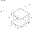
- FIG. 1a is a perspective view illustrating a shoe care device 1 according to an embodiment of the present invention.
- FIG. 1a illustrates a state in which an internal space (hereinafter, referred to as 'accommodation space 10') of the shoe care device 1 is closed.
- FIG. 1b is a perspective view illustrating a state in which a shoe S is stored in the accommodation space 10 of the shoe care device 1 of FIG. 1a .
- the shoe care device 1 is configured to include a body 100 and a moving body 200.
- the body 100 and the moving body 200 form the accommodation space 10 accommodating the shoe S jointly.
- the body 100 and the moving body 200 are coupled to move with respect to each other.
- the moving body 200 may be coupled to the body 100 to reciprocally move in a horizontal direction.
- the shoe care device 1 illustrated in FIG. 1a may be changed like the shoe care device 1 illustrated in FIG. 2a . That is, the moving body 200 may slidably move in a first direction X with respect to the body 100, and the shoe care device 1 is transformed from the closed state to the opened state, and the accommodation space 10 may be opened.
- the shoe care device 1 illustrated in FIG. 2a may be changed like the shoe care device 1 illustrated in FIG. 1a again. That is, the moving body 200 may slidably move in an opposite direction to the first direction X with respect to the body 100, and the shoe care device 1 is transformed from the opened state to the closed state, and the accommodation space 10 may be closed.
- the moving body 200 may move the first direction X or the opposite direction to the first direction X with respect to the body 100, and reciprocally move in front and rear directions.
- the accommodation space 10 may be sealed from outside air. Therefore, when the shoe S is accommodated in the accommodation space 10 and the accommodation space 10 is closed, a contact of the shoe S with dust and moisture of the outside air may be interrupted.
- a moving body 200 may be moved relative to a main body 100 manually or automatically. That is, in the former case, a user may hold a portion of the moving body 200 and move the moving body 200, and in the latter case, the moving body 200 may be moved by a separate actuator.
- the body 100 may form an upper surface and a rear surface of the accommodation space 10.
- the moving body 200 may form a front surface, a lower surface, and both side surfaces of the accommodation space 10.
- the accommodation space 10 may be formed in a hexahedral form.
- the accommodation space 10 of the shoe care device 1 according to the embodiment of the present invention is not limited to such a shape, and may be configured in various three-dimensional shapes.
- the body 100 and the moving body 200 may form an overall appearance of the shoe care device 1.
- An exterior of the shoe care device 1 may be configured in the hexahedral form. That is, in the state in which the body 100 and the moving body 200 are coupled to each other and the accommodation space 10 is closed, the external appearance of the shoe care device 1 may be configured in the hexahedral form.
- the shoe care device 1 according to the embodiment of the present invention is not limited to such a shape, and may be configured in various three-dimensional shapes.
- the body 100 may include an upper body 130, a middle body 120, and a lower body 110.
- the upper body 130 is positioned at an upper side of the accommodation space 10.
- the upper body 130 forms the upper surface of the accommodation space 10.
- the upper body 130 may form an uppermost portion of the shoe care device 1.
- the upper surface of the upper body 130 may form a flat surface along a substantially horizontal surface.
- the lower body 110 is positioned below the accommodation space 10.
- the lower body 110 may form a lowermost portion of the shoe care device 1.
- the lower body 110 may form a bottom portion of the shoe care device 1.
- the middle body 120 is positioned behind the accommodation space 10.
- the middle body 120 forms the rear surface of the accommodation space 10.
- the middle body 120 may connect the upper body 130 and the lower body 110 behind the accommodation space 10.
- the middle body 120 may form a rear wall surface of the shoe care device 1.
- the body 100 is configured to include the upper body 130, the middle body 120, and the lower body 110, and as a result, the body 100 may form a substantially 'C' form on the side view.
- the moving body 200 is configured to move forward and backward with respect to the body 100.
- the moving body 200 may include a base 220, a transparent window 210, and a turntable 230.
- the base 220 may be coupled to the lower body 110 to be slidably movable in the first direction X.
- the base 220 may form the bottom portion of the moving body 200.
- the base 220 may be positioned at the upper side of the lower body 110.
- a bottom surface of the base 220 may be positioned in close contact with or in proximity to the upper surface of the lower body 110.
- the transparent window 210 may form of extending upward from the base 220.
- the transparent window 210 may form the front surface, and both side surfaces (a left surface and a right surface) of the accommodation space 10.
- the transparent window 210 may be made of a transparent or translucent material.
- the transparent window 210 may be made of a material which is weather-resistant to prevent discoloration.
- the transparent window 210 may be made of an acrylic (PMMA) material which is weather-resistant and scratch-resistant.
- the transparent window 210 may prevent a beam having a predetermined wavelength from being introduced into the accommodation space 10.
- the transparent window 210 may be configured to block ultraviolet rays.
- the ultraviolet rays as an electromagnetic wave in which a wavelength corresponds to 10 to 397 nm shorter than visible rays are light which has a strong chemical action and causes getting sunburn or discoloration.
- an ultraviolet-proof film may be attached to an inner surface or an outer surface of the transparent window 210.
- the inner surface or the outer surface of the transparent window 210 may be UV-coated with an ultraviolet-proof agent.
- the transparent window 210 includes a first window 211, a second window 212, and a third window 213.
- the first window 211 may form the front surface of the accommodation space 10.
- the second window 212 may form the left surface of the accommodation space 10.
- the third window 213 may form the right surface of the accommodation space 10.
- the shoe care device 1 may be used as a device which may display the shoe S while keeping and caring the shoe S.
- the accommodation space 10 may be sealed from the outside air.
- the accommodation space 10 may be formed in the hexahedral form.
- the moving body 200 may be present at a first location and the shoe care device 1 is in the closed state.
- the accommodation space 10 may be opened.
- an upper portion of the first window 211 is spaced to a front side in the first direction X from the front surface of the upper body 130 to form a gap (hereinafter, referred to as 'first gap').
- an upper portion of the first window 212 is spaced to a front side in the first direction X from the front surface of the upper body 120 to form a gap (hereinafter, referred to as 'first gap').
- the third window 213 is spaced to the front side in the first direction X from a right side surface of the middle body 120 to form a gap (hereinafter, referred to as 'third gap').
- the moving body 200 In the state in which the moving body 200 moves in the first direction X as much as possible, i.e., in the state in which the moving body 200 is positioned relatively at a frontmost side, the moving body 200 may be present at a second location and the shoe care device 1 may be in the opened state.
- the user may put the shoe S into the accommodation space 10 or withdraw the shoe S from the accommodation space 10 through the first gap.
- the user may access the interior of the accommodation space 10 through the second gap and the third gap.
- the turntable 230 may form the upper surface on which the shoe S is placed.
- the upper surface of the turntable 230 may have a circular shape.
- the turntable 220 may form the lower surface of the accommodation space 10 jointly with the base 220.
- the turntable 230 may be rotatably coupled to the base 220 around a vertical axis, i.e., an axis parallel to a third direction Z.
- a motor 290 may be provided in the moving body 200.
- the motor 290 may be coupled to the base 220.
- the turntable 230 may rotate in conjunction with the rotation of the motor 290.
- Rotational force of the motor 290 may be delivered to the turntable 230 through a reducer.
- the motor 290 may rotate unidirectionally or reciprocally rotate bidirectionally.
- the turntable 230 is provided, and as a result, the shoe S may rotate in the accommodation space 10 or a display effect of the shoe S may be enhanced.
- the shoe care device 1 may have a concave lower body groove 119 in the upper central portion of the lower body 110.
- the lower body groove 119 may have a shape that is open toward the front side of the lower body 110.
- the motor 290 may be placed in the lower body groove 119.
- the shoe care device 1 may include an operating button 610 and a controller 600.
- the operating button 610 may be formed in the body 100.
- the operating button 610 may be formed on the front surface of the upper body 130.
- the turntable 230 may rotate or stop.
- the user manipulates the operating button 610 to adjust a rotational speed of the turntable 230.
- the user may input a rotation time of the turntable 230 into the controller 600 through the operating button 610.
- the user manipulates the operating button 610 to rotate the turntable 230 at a predetermined angle.
- the user may place the shoe S on the upper surface of the turntable 230 by holding any one part (heel top, lining, tong, etc.) of the shoe S. Thereafter, the user manipulates the operating button 610 to rotate the turntable 230 at a predetermined angle.
- the user manipulates the operating button 610 to rotate the turntable 230 at a predetermined angle so that a front and rear direction of the shoe S coincides with the first direction X.
- the user manipulates the operating button 610 to rotate the turntable 230 at a predetermined angle so that the front and rear direction of the shoe S form a predetermined angle with the first direction X.
- the shoe S may be placed (displaced) in a direction desired by the user.
- a sensor (not illustrated) that senses movement of the moving body 200 may be provided in the body 100.
- the controller 600 may rotate the turntable 230 by a signal of the sensor.
- a load sensor (not illustrated) may be provided in the base 220.
- the load sensor may automatically measure a load of the shoe S placed on the turntable 230.
- the rotational speed of the turntable 230 according to a measurement value of the load sensor may be set in the controller 600.
- the user may input the rotational speed of the turntable 230 according to the measurement value of the load sensor into the controller 600 through the operating button 610.
- a camera (not illustrated) may be provided in the shoe care device 1.
- the camera may automatically shoot the shoe S placed on the turntable 230.
- the controller 600 may recognize the shape, size, and/or type of the shoe S through a shooting image of the camera.
- the rotational speed of the turntable 230 according to the shape, size, and/or type of the shoe S may be set in the controller 600.
- the user may input the rotational speed of the turntable 230 according to the shape, size, and/or type of the shoe S into the controller 600 through the operating button 610.
- the shoe care device 1 may include an operating sensor.
- the operating sensor may sense an access of the user.
- the turntable 230 may be rotated or stopped by the sensing signal of the operating sensor.
- FIG. 2a is a front view illustrating the use state of the shoe care device 1 of FIG. 1b .
- FIG. 2b illustrates an air flow in the accommodation space 10.
- FIG. 2b is a side view illustrating a use state of the shoe care device 1 of FIG. 1b .
- FIG. 2b illustrates a state of illuminating the shoe S in the accommodation space 10.
- the shoe care device 1 may include a first light 410.
- the first light 410 may be provided in the upper body 130.
- the first light 410 may illuminate the accommodation space 10.
- the first light 410 may include a light source 411.
- the light source 411 may intensively irradiate light onto the upper surface of the turntable 230 on which the shoe S is placed.
- the light of the light source 411 may intensively illuminate the shoe S placed on the upper surface of the turntable 230.
- an image of the shoe S stored in the accommodation space 10 may be changed by the light of the light source 411..
- the light source 411 When the user manipulates the operating button 610, the light source 411 may be turned on or off. The user may input an operating time of the light source 411 into the controller 600 through the operating button 610. The user manipulates the operating button 610 to adjust the operating time of the light source 411.
- the light source 411 may be turned on or off by the sensing signal of the operating sensor.
- the controller 600 may turn on-off the light source by the signal of the operating sensor.
- the light source 411 may be turned on or off by the sensing signal of the sensor.
- the controller 600 may turn on-off the light source by the signal of the sensor.
- the operating time and the operating pattern of the light source according to the measurement value of the load sensor may be set in the controller 600.
- the user may input the operating time and the operating pattern of the light source 411 according to the measurement value of the load sensor into the controller 600 through the operating button 610.
- the operating time and the operating pattern of the light source according to the shape, size, and/or type of the shoe S may be set in the controller 600.
- the user may input the operating time and the operating pattern of the light source 411 according to the shape, size, and/or type of the shoe S into the controller 600 through the operating button 610.
- the light source 411 may be configured to change the color of the light.
- the light source 411 may be constituted by Red Green Blue White (RGBW) LEDs.
- the controller 600 may control current applied to a Red (R) LED, a Green (G) LED, a Blue (B) LED, and a White (W) LED.
- R Red
- G Green
- B Blue
- W White
- the controller 600 controls the current applied to the RGBW LEDs, the aesthetics and a color sense of the shoe S stored in the accommodation space 10 may be variously changed.
- the user may input a pattern of the current applied to the RGBW LED into the controller 600 through the operating button 610.
- FIG. 3a as a cross-sectional view illustrating a body 100 according to an embodiment of the present invention is a diagram showing an upper body 130 taken along line A-A' of FIG. 2a .
- FIG. 3b as a cross-sectional view illustrating the body 100 according to an embodiment of the present invention is a diagram illustrating the upper body 130 from the bottom.
- the body 100 may be configured to include an air path 300.
- the body 100 may be configured to include a suction port 310 and a discharge port 320.
- the air path 300 may be formed in the upper body 130.
- the air path 300 may be provided inside the upper body 130.
- the air path 300 connects the suction port 310 and the discharge port 320.
- the suction port 310 may form an inlet of the air path 300, and the discharge port 320 may form an outlet of the air path 300.
- the suction port 310 may be formed on a bottom surface of the upper body 130.
- the discharge port 320 may be formed on the bottom surface of the upper body 130.
- the air in the accommodation space 10 may be suctioned into the air path 300 through the suction port 310.
- the air in the air path 300 may be discharged to the accommodation space 10 through the discharge port 320. Therefore, air forcibly blown by a blowing part 330 to be described below may be circulated in the accommodation space 10 and the air path 300.
- the shoe care device 1 may include the blowing part 330 and a heating part 340.
- the blowing part 330 and the heating part 340 may be provided in the upper body 130.
- the blowing part 330 is configured to circulate the air in the accommodation space 10.
- the blowing part 330 may be positioned in the upper body 130.
- the blowing part 330 may be placed in the air path 300, and may generate a flow of the air in the air path 300.
- the heating part 340 may be configured to directly or indirectly heat the air in the accommodation space 10.
- the heating part 340 may be placed in the body 100.
- the heating part 340 may be placed in the air path 300.
- the body 100 may be configured to include the first light 410 and a second light 420.
- the first light 410 may be configured to be formed on the bottom surface of the upper body 130 and to illuminate the accommodation space 10.
- the second light 420 may be configured to be formed on the bottom surface of the upper body 130 and to illuminate the middle body 120 behind the first light 410.
- the heating part 340 may deliver thermal energy to the air which moves in the air path 300.
- the heating part 340 may be configured to include a heat wire 341.
- the blowing part 330 and the heating part 340 may control the temperature and/or humidity of the accommodation space 10.
- the blowing part 330 may rotate or stop.
- the user manipulates the operating button 610 to adjust the rotational speed of the blowing part 330.
- the user may input the rotation time of the blowing part 330 into the controller through the operating button 610.
- the air in the accommodation space 10 may be circulated by operating the blowing part 330, and the air in the accommodation space 10 may maintain a uniform state as a whole.
- the heating part 340 When the user manipulates the operating button 610, the heating part 340 may be turned on or off. The user manipulates the operating button 610 to adjust the operating time of the heating part 340. The user may input an operating temperature of the heating part 340 into the controller through the operating button 610. The temperature of the air heated by the heating part 340 may be selected or adjusted according to characteristics of a used shoe S.
- the blowing part 330 and the heating part 340 may be operated for a predetermined time. Further, each of the operating and the stopping of the blowing part 330 and the heating part 340 may be repeatedly conducted for a predetermined time. The time may be decided by the user, or automatically decided by a program.
- the temperature and/or the humidity of the accommodation space 10 may be maintained at an optimal state which is suitable for the characteristics of each shoe S.
- the shoe care device 1 may achieve both a shoe display effect of displaying the shoe and a shoe care effect of interrupting deformation or contamination of the shoe.
- the blowing part 330 and the heating part 340 may be turned on or off by the sensing signal of the sensor.
- the controller 600 may turn on-off the blowing part 330 and the heating part 340 by the signal of the sensor.
- the operating time and the operating pattern of the blowing part 330 and the heating part 340 according to the measurement value of the load sensor may be set in the controller.
- the user may input the operating time and the operating pattern of the blowing part 330 and the heating part 340 according to the measurement value of the load sensor into the controller through the operating button.
- the operating time and the operating pattern of the blowing part 330 and the heating part 340 according to the shape, size, and/.or type of the shoe may be set in the controller.
- the user may input the operating time and the operating pattern of the blowing part 330 and the heating part 340 according to the shape, size, and/.or type of the shoe into the controller through the operating button.
- the shoe care device 1 controls the temperature and/or the humidity of the accommodation space 10 differently according to a material, a load, the shape, the size, and/or the type of the shoe to completely interrupt the deformation or the contamination of the shoe.
- the lower body 100 of the body 100 forms the bottom surface of the shoe care device 1.
- the lower body 110 may be configured to support the lower side of the moving body 200.
- the middle body 120 of the body 100 extends upward from a rear side of the lower body 110 and forms a back surface of the shoe care device 1.
- the inner surface of the middle body 120 forms the back surface of the accommodation space 10.
- the upper body 130 of the body 100 extends forward from the upper side of the middle body 120 and forms the upper surface of the shoe care device 1.
- the inner surface of the upper body 130 may forms the upper surface of the accommodation space 10.
- the upper body 130 may be configured to support the upper side of the moving body 200.
- the body 100 may be configured in a symmetric form around a reference plane RP orthogonal to the second direction Y.
- the moving body 200 forms the accommodation space 10 jointly with the body 100.
- the moving body 200 may be movably coupled to the body 100 between a first location and a second location.
- the second location is a location before the first location.
- the moving body 200 may be coupled to the body 100 to be movable forward and backward with respect to the body 100.
- the accommodation space 10 When the moving body 200 is at the first location, the accommodation space 10 is closed and when the moving body 200 is at the second location, the accommodation space 10 is opened.
- the accommodation space 10 of the shoe care device 1 is opened at the upper side, the left side, and the right side.
- the moving body 200 When the moving body 200 moves forward and backward with respect to the body 100, the moving body 200 may be supported by the lower body 110 and the upper body 130.
- both left and right sides at the upper side and both left and right sides at the lower side of the moving body 200 are supported by the body 100.
- both left and right sides at the upper side and both left and right sides at the lower side of the moving body 200 may be supported by the body 100.
- the moving body 200 may be symmetrical about a reference plane RP.
- the transparent window 210 may be integrally configured. That is, respective parts constituting the transparent window 210 is not configured to be connected or fixed to each other by a fixation means (e.g., a bracket, a clip, a bolt, an adhesive, etc.), but the transparent window 210 may be configured as one body from the time of manufacturing. All parts constituting the transparent window 210 may be made of the same material. All parts constituting the transparent window 210 may be configured to have the same made of the same physical property.
- a fixation means e.g., a bracket, a clip, a bolt, an adhesive, etc.
- the transparent window 210 may be formed by injection molding.
- a substantial part of the transparent window 210 or all parts of the transparent window 210 may be configured to be transparent.
- the transparent window 210 may be configured by a combination of plates constituting planes which are distinguished from each other.
- the plates constituting the transparent window 210 are connected to each other.
- the plates constituting the transparent window 210 are connected to each other at respective corners.
- a part where the plates are connected in the transparent window 210 may form a bent form, a curved surface, or a flat surface.
- the transparent window 210 may be made of polymethyl methacrylate (PMMA).
- the transparent window 210 includes a first window 211, a second window 212, and a third window 213.
- Each of the first window 211, the second window 212, and the third window 213 is configured to be transparent.
- Each of the first window 211, the second window 212, and the third window 213 may be configured in a flat plate form.
- Each of the first window 211, the second window 212, and the third window 213 may be configured in a square plate form. Vertical heights of the respective windows of the first window 211, the second window 212, and the third window 213 may be the same as or similar to each other.
- the first window 211 forms the front surface of the shoe care device 1
- the second window 212 forms the left surface of the shoe care device 1
- the third window 213 forms the right surface of the shoe care device 1.
- the second window 212 extends to a rear side from a left end of the first window 211
- the third window 213 extends to the rear side from a right end.
- the first window 211 forms the front surface of the transparent window 210
- the second window 212 forms the left surface of the transparent window 210
- the third window 213 forms the right surface of the transparent window 210.
- An inner surface and an outer surface of the first window 211 may form surfaces orthogonal to the first direction.
- the inner surface and the outer surface of the second window 212 may form surfaces orthogonal to the second direction.
- the inner surface and the outer surface of the third window 213 may form surfaces orthogonal to the second direction.
- the inner surface of the first window 211 forms the front surface of the accommodation space 10.
- the inner surface of the second window 212 forms the left surface of the accommodation space 10.
- the inner surface of the third window 213 forms the right surface of the accommodation space 10.
- the transparent window 210 includes the first window 211, the second window 212, and the third window 213, and as a result, the transparent window 210 may be configured in a substantially C shape (or ⁇ shape, ⁇ shape, or shape) on a plan view.
- the transparent window 210 may be configured in a symmetric form around the reference plane RP.
- the second window 212 and the third window 213 may be configured symmetric to each other around the reference plane RP.
- the upper body 130 and the first window 211 may be opened/closed to each other
- the middle body 120 and the second window 212 may be opened/closed to each other
- the middle body 120 and the third window 213 may be opened/closed to each other.
- the lower side of the second window 212 and the lower side of the third window 213 may be supported on the lower body 110.
- the upper side of the second window 212 and the upper side of the third window 213 may be supported on the upper body 130.
- the transparent window 210 may be integrally formed.
- the transparent window 210 may form an area of substantial parts of the front surface, the left surface, and the right surface of the shoe care device 1.
- An area of the first window 211 may be configured to correspond to the area of the front surface of the accommodation space 10.
- the area of the second window 212 may be configured to correspond to the area of the left surface of the accommodation space 10.
- the area of the third window 213 may be configured to correspond to the area of the right surface of the accommodation space 10.
- the area of the transparent window 210 may be maximized, the shoe S accommodated in the accommodation space 10 may not be blocked, but well viewed at all of the front side, the left side, and the right side, and the display effect of the shoe S may be increased.
- the shoe S when the transparent window 210 is formed only on the front surface of the shoe care device 1, the shoe S may not be viewed at the left side or the right side of the shoe care device 1, and the display effect of the shoe may not be sufficiently shown.
- first window 211 and the second window 212 are not integrally configured (further, if the first window 211 and the third window 213 are not integrally configured)
- a boundary between the first window 211 and the second window 212 is viewed to the user, and the boundary may visually block the shoe inside the accommodation space 10 and the display effect of the shoe may be reduced, and the satisfaction of the user may be lowered.
- a gap may be generated between the boundaries, and foreign substances may be introduced into the accommodation space 10 through the gap.
- the base 220 is fixedly coupled to the lower side of the transparent window 210 to form a lower portion of the moving body 200.
- An entire form of the base 220 may be configured as a flat form in the horizontal direction.
- the base 220 may be configured in the square form on the plan view.
- the base 220 may be configured so that the shoe S is placed at the upper side of the base 220.
- An upper surface of the base 220 may be configured substantially in the square form.
- the base 220 is positioned at the upper side of the lower body 110.
- the upper surface of the base 220 is positioned at the upper side of the lower body 110.
- the base 220 is coupled to the lower body 110 to be movable forward and backward.
- the turntable 230 is rotatably coupled around a perpendicular rotational axis (the rotational axis aligns with the center axis of the turntable 230) at the upper side of the base 220.
- the turntable 230 is configured in a circular plate form.
- the upper surface of the turntable 230 may be configured to be in parallel to the first direction X and the second direction Y.
- the height of the upper surface of the base 220 may be configured to correspond to or coincide with the height of the upper surface of the turntable 230.
- the shoe While the transparent window 210 and the base 220 move forward with respect to the body 100, the shoe may be seated on the base 220 or the show may be withdrawn from the base 220 through the space between the upper body 130 and the first window 211. Further, in this case, the user may access the shoe or an upper space through the space between the middle body 120 and the second window 212 or between the middle body 120 and the third window 213. Further, in this case, the user easily accesses the inner surface of each of the lower body 110, the middle body 120, and the upper body 130.
- the moving body 200 is configured to include the turntable 230 in the shoe care device 1 according to the embodiment of the present invention. Therefore, a shoe care device 1 may be provided in which both circulation of the air and rotation of the shoe are conducted in the accommodation space 10, and as a result, both the management of the shoe and the display effect of the shoe are excellent.
- the moving body 200 may be configured to include a lower guard 240.
- the lower guard 240 is fixedly coupled to an outer side of a border of the base 220.
- the lower guard 240 is fixedly coupled to a front surface, a left surface, and a right surface of the base 220.
- the lower guard 240 may be configured substantially in the C shape (or ⁇ shape, ⁇ shape, or shape) on the plan view. On the plan view, the shape of the lower guard 240 may be configured to correspond to the shape of the transparent window 210.
- the lower guard 240 may be positioned outside the lower body 110.
- FIG. 4 is a perspective view illustrating a moving body 200 according to an embodiment of the present disclosure.
- FIG. 5 is a perspective view illustrating an accommodation space 10 in the opened state in the shoe care device 1 according to an embodiment of the present disclosure.
- the transparent window 210 may be configured to include a first fin portion 212a and a second fin portion 213a (see FIG. 4 ).
- the first fin portion 212a extends to the upper side from the rear side of the second window 212.
- the first fin portion 212a is configured to protrude upward on a rear upper end of the second window 212.
- the first fin portion 212a is configured in a flat plate form.
- the first fin portion 212a configured integrally with the second window 212 may be configured to be transparent.
- the inner surface of the first fin portion 212a may form the same plane as the inner surface of the second window 212.
- the outer surface of the first fin portion 212a may form the same plane as the inner surface of the second window 212.
- the inner surface of the first fin portion 212a may be configured to be stepped with the inner surface of the second window 212.
- the outer surface of the first fin portion 212a may be configured to be stepped with the inner surface of the second window 212.
- the second fin portion 213a extends upward on the rear side of the third window 213.
- the second fin portion 213a is configured to protrude upward on the rear upper end of the third window 213.
- the second fin portion 213a is configured in the flat plate form.
- the second fin portion 213a configured integrally with the third window 213 may be configured to be transparent.
- the inner surface of the second fin portion 213a may form the same plane as the inner surface of the third window 213.
- the inner surface of the second fin portion 213a may form the same plane as the inner surface of the third window 213.
- the inner surface of the second fin portion 213a may be configured to be stepped with the inner surface of the third window 213.
- the outer surface of the second fin portion 213a may be configured to be stepped with the inner surface of the third window 213.
- the upper body 130 may be configured to include a first insertion groove 131, a first stopper 132, a second insertion groove 133, and a second stopper 134 (see FIG. 3b ).
- the first insertion groove 131 is configured in a narrow gap or slit form so that the first fin portion 212a is inserted and moves.
- the first insertion groove 131 is formed on the bottom of the upper body 130 in the first direction.
- the first stopper 132 is configured to be provided in front of the first insertion groove 131 to prevent forward movement of the first fin portion 212a.
- the front end of the first fin portion 212a touches the rear end of the first stopper 132.
- the second insertion groove 133 is configured in the narrow gap or slit form so that the second fin portion 213a is inserted and moves.
- the second insertion groove 133 is formed on the bottom of the upper body 130 in the first direction.
- the second stopper 134 is configured to be provided in front of the second insertion groove 133 to prevent forward movement of the second fin portion 213a.
- the front end of the second fin portion 213a touches the rear end of the second stopper 134.
- the first fin portion 212a may slidably move stably forward and backward along the first insertion groove 131, and the second fin portion 213a may slidably move stably forward and backward along the second insertion groove 133.
- the first fin portion 212a is prevented from forward movement while being inserted into the first insertion groove 131 by the first stopper 132, and the second fin portion 213a is prevented from forward movement while being inserted into the second insertion groove 133 by the second stopper 134, and the upper side of the moving body 200 is stably supported by the body 100.
- the lower side of the transparent window 210 is supported on the lower body 110 of the body 100 through the base 220 and the lower guard 240.
- both the left and right sides at the upper side and both the left and right sides at the lower side of the moving body 200 are supported by the body 100.
- the accommodation space 10 may be opened at the upper side, the left side, and the right side, and the shoe may be inserted into the accommodation space 10 or the shoe may be withdrawn from the accommodation space 10, and in this case, the upper side and the lower side of each of the second window 212 and the third window 213 are supported by the body 100, and stable coupling between the body 100 and the moving body 200 is maintained.
- the transparent window 210 may be configured to include a third fin portion 212b and a fourth fin portion 213b (see FIG. 4 ).
- the third fin portion 212b extends backward on the rear end of the second window 212.
- the third fin portion 212b is configured to protrude backward on the rear end of the second window 212.
- the third fin portion 212b is configured in the flat plate form.
- the third fin portion 212b configured integrally with the second window 212 may be configured to be transparent.
- the inner surface of the third fin portion 212b may form the same plane as the inner surface of the second window 212.
- the outer surface of the third fin portion 212b may form the same plane as the inner surface of the second window 212.
- the inner surface of the third fin portion 212b may be configured to be stepped with the inner surface of the second window 212.
- the outer surface of the third fin portion 212b may be configured to be stepped with the inner surface of the second window 212.
- the inner surface of the third fin portion 212b may form the same plane as the inner surface of the first fin portion 212a and the outer surface of the third fin portion 212b may form the same plane as the outer surface of the first fin portion 212a.
- a thickness of the third fin portion 212b may be configured to be the same as the thickness of the first fin portion 212a.
- Each of the thickness of the first fin portion 212a and the thickness of the third fin portion 212b may be configured to be thinner than the thickness of the second window 212.
- the fourth fin portion 213b extends backward on the rear end of the third window 213.
- the fourth fin portion 213b is configured to protrude backward on the rear end of the third window 213.
- the fourth fin portion 213b is configured in the flat plate form.
- the fourth fin portion 213b configured integrally with the third window 213 may be configured to be transparent.
- the inner surface of the fourth fin portion 213b may form the same plane as the inner surface of the third window 213.
- the outer surface of the fourth fin portion 213b may form the same plane as the inner surface of the third window 213.
- the inner surface of the fourth fin portion 213b may be configured to be stepped with the inner surface of the third window 213.
- the outer surface of the fourth fin portion 213b may be configured to be stepped with the inner surface of the third window 213.
- the inner surface of the fourth fin portion 212b may form the same plane as the inner surface of the second fin portion 213a and the outer surface of the fourth fin portion 213b may form the same plane as the outer surface of the second fin portion 213a.
- the thickness of the fourth fin portion 213b may be configured to be the same as the thickness of the second fin portion 213a.
- Each of the thickness of the second fin portion 213a and the thickness of the fourth fin portion 213b may be configured to be thinner than the thickness of the third window 213.
- the middle body 120 may be configured to include a third insertion groove 121 and a fourth insertion groove 122.
- the third insertion groove 121 is configured in the narrow gap or slit form so that the third fin portion 212b is inserted.
- the third insertion groove 121 is formed on the front surface of the middle body 120 in the third direction.
- the fourth insertion groove 122 is configured in the narrow gap or slit form so that the fourth fin portion 213b is inserted.
- the fourth insertion groove 122 is formed on the front surface of the middle body 120 in the third direction.
- the third insertion groove 121 may be formed adjacent to one edge of the middle body 120, and the fourth insertion groove 122 may be formed adjacent to the edge of the middle body 120 opposite to the third insertion groove 121. (see FIG. 5 )
- the third fin portion 212b is inserted into the third insertion groove 121 and the fourth fin portion 213b is inserted into the fourth insertion groove 122, and the moving body 200 and the body 100 are stably coupled, and the accommodation space 10 is effectively sealed.
- FIG. 6A is a cross-sectional view illustrating a portion of the shoe care device 1 according to an embodiment of the present disclosure.
- FIG. 6B is a cross-sectional view illustrating the portions where sliding rails 250 and brackets 260 are coupled in the shoe care device 1 according to an embodiment of the present disclosure.
- FIG. 7 is a cross-sectional view illustrating a portion of the shoe care device 1 according to an embodiment of the present disclosure.
- FIG. 8A is a perspective view illustrating the state in which the brackets 260 and the sliding rails 250 are coupled to a lower body 110 of the shoe care device 1 according to an embodiment of the present disclosure
- FIG. 8B is a perspective view illustrating the state in which the sliding rails 250 in FIG. 8A are moved.
- FIG. 9 is a perspective view illustrating the bottom side of the moving body 200 of the shoe care device 1 according to an embodiment of the present disclosure.
- the shoe care device 1 includes a bracket 260 and a sliding rail 250.
- the bracket 260 is fixedly coupled to the lower body 110.
- the bracket 260 may be fixed to the lower body 110 by various fixing elements (e.g., bolts, rivets, and clamps), or may be fixed to the lower body 110 by various fixing methods (e.g., hooking and welding).
- the bracket 260 includes a slider 261.
- the slider 261 may be configured integrally with the bracket 260, or may be configured separately and then fixed to the bracket 260.
- the slider 261 is coupled to the sliding rail 250 to be movable relative to each other.
- the slider 261 is fixedly coupled to the lower body 110 of the main body 100
- the sliding rail 250 is fixedly coupled to the base 220 of the moving body 200
- the relative movement direction between the slider 261 and the sliding rail 250 coincides with the relative movement direction of the main body 100 and the moving body 200.
- the slider 261 and the sliding rail 250 may each be configured in the form of a slide rail.
- Each of the sliding rail 250 and the slider 261 according to an embodiment of the present disclosure may be configured in the form of a rail such that the sliding rail and the slide move relative to each other in the longitudinal direction (see FIG. 6A ).
- the slider 261 and the sliding rail 250 may be configured in the form of an LM guide or a linear actuator. That is, the sliding rail 250 according to an embodiment of the present disclosure may be configured as a rail of an LM guide or a linear actuator, and the slider 261 according to an embodiment of the present disclosure may be configured as a block (or a carriage or slider) coupled to be movable along the rail of the LM guide or the linear actuator.
- balls 253 and a retainer 254 may be interposed between the slider 261 and the sliding rail 250.
- the shoe care device 1 may include one or more brackets 260.
- At least a portion of the sliding rail 250 has a constant cross section along the front and rear direction and is coupled to the slider 261 to be movable back and forth. That is, the sliding rail 250 is coupled to the slider 261 to be reciprocally movable in a first direction X relative to the slider 261.
- the sliding rail 250 is coupled to the bottom surface of the base 220.
- the shoe care device 1 may include one or more sliding rails 250.
- a rail coupling portion 225 may be provided on the bottom surface of the base 220 for coupling with the sliding rail 250.
- the rail coupling portion 225 may be provided in the first direction X.
- the number and positions of rail coupling portions 225 correspond to the number and positions of the sliding rails 250.
- the sliding rail 250 may be fixed to the base 220 (the rail coupling portion 225) by various fixing elements (e.g., bolts, rivets, and clamps) or by various fixing methods (e.g., hooking and welding).
- various fixing elements e.g., bolts, rivets, and clamps
- various fixing methods e.g., hooking and welding
- the sliding rail 250 may be fixedly coupled to the base 220 by a bolt 255.
- the bolt 255 may penetrate a through-hole 252 of the sliding rail 250 to be fastened to the sliding rail 250, and may also be inserted into a fastening hole 225a in the rail coupling portion 225 to be fixed to the rail coupling portion 225.
- a plurality of bolts 255 may be provided and coupled to the sliding rail 250 and the rail coupling portion 225 while being spaced apart from each other in the longitudinal direction (the first direction X).
- a plurality of balls 253 may be interposed between the slider 261 and the sliding rail 250 to reduce friction.
- the balls 253 has a spherical shape.
- the balls 253 are configured to prevent or reduce direct contact between the slider 261 and the sliding rail 250, thereby reducing the friction force generated between the slider 261 and the sliding rail 250.
- the balls 253 may be supported by a retainer 254.
- a retainer 254 holes each having a diameter slightly smaller than the diameter of each ball 253 are in the longitudinal direction, and each ball 253 may be supported while being accommodated in one of the holes of the retainer 254.
- the retainer 254 is provided in the first direction X.
- the length of the retainer 254 may be smaller than the length of the sliding rail 250 and greater than the length of the slider 261.
- the sum of the length of the retainer 254 and the length of the slider 261 may be greater than the length of the sliding rail 250.
- the retainer 254 may move relative to the slider 261 and may move relative to the sliding rail 250.
- the plurality of balls 253 may be spaced apart at predetermined intervals in the relative movement direction (the direction parallel to the first direction X) between the slider 261 and the sliding rail 250.
- the slider 261 and the sliding rail 250 may be configured to prevent relative movement in a direction other than the front and rear direction.
- the sliding rail 250 may be configured to move relative to the slider 261 only in a direction parallel to the first direction X and to be prevented from moving in a direction parallel to the second direction Y and a direction parallel to the third direction Z.
- the slider 261 and the sliding rail 250 may be configured to be prevented from relatively moving in a direction parallel to the second direction Y and in a direction parallel to the third direction Z by the balls 253 interposed therebetween (see FIG. 6A ).
- the slider 261 and the sliding rail 250 may be engaged with each other to prevent relative movement in a direction other than the front and rear direction.
- the slider 261 and the sliding rail 250 both have a constant cross section along the first direction X, in which the slider 261 may have a first engagement portion 261a, and the sliding rail 250 may include a second engagement portion 251 (see FIG. 7 ).
- the first engagement portion 261a and the second engagement portion 251 are configured to be engaged with each other when the sliding rail 250 moves in a direction parallel to the second direction Y relative to the slider 261.
- the first engagement portion 261a and the second engagement portion 251 are configured to be engaged with each other when the sliding rail 250 moves in a direction parallel to the third direction Z relative to the slider 261.
- the sliding rail 250 may include a first engagement ledge 256 and a second engagement ledge 257.
- the first engagement ledge 256 may be provided on one side of the sliding rail 250 and the second engagement ledge 257 may be provided on the other side of the sliding rail 250.
- the first engagement ledge 256 and the second engagement ledge 257 may be provided at opposite ends of the sliding rail 250 in the longitudinal direction.
- the first engagement ledge 256 may be formed by bending the front end of the sliding rail 250, and the second engagement ledge 257 may be formed by bending the rear end of the sliding rail 250.
- the slider 261 is coupled to the inside of the sliding rail 250, and the retainer 254 may be interposed between the sliding rail 250 and the slider 261 while supporting each ball 253 inside the sliding rail 250 (see FIGS. 6A and 6B ).
- the front end of the slider 261 and the front end of the retainer 254 may be located in contact with or close to the inside of the first engagement ledge 256.
- the rear end of the slider 261 and the rear end of the retainer 254 may be located in contact with or close to the inside of the second engagement ledge 257.
- the first engagement ledge 256 and the second engagement ledge 257 may maintain the coupling of the sliding rail 250, the balls 253, the retainer 254, and the slider 261 to limit the range of movement to move in a predetermined stroke when the sliding rail 250 reciprocally moves along the first direction X relative to the slider 261.
- two brackets 260 and two sliding rails 250 may be provided to be symmetrically spaced apart on both left and right sides, respectively, with respect to the center of the shoe care device 1. That is, two brackets 260 may be arranged symmetrically with reference to a reference plane RP that vertically crosses the center of the shoe care device 1, and two sliding rails 250 may be arranged symmetrically with reference to the reference plane RP.
- the moving body 200 is moved stably and smoothly relative to the main body 100 by the slider 261 of the bracket 260 and the sliding rail 250.
- the friction generated between the slider 261 and the sliding rail 250 is reduced to allow the user to easily open or close the moving body 200 from the main body 100 with relatively small force, and the sliding rail 250 is moved relative to the slider 261 along the front and rear direction to ensure stable movement of the moving body 200.
- FIG. 10A is a view schematically illustrating the lower body 110 of the shoe care device 1 according to an embodiment of the present disclosure.
- FIG. 10B is a diagram schematically illustrating a state in which the moving body 200 moves forward relative to the main body 100 in the shoe care device 1 according to an embodiment of the present disclosure.
- the bracket 260 may be located adjacent to the front end of the lower body 110.
- the bracket 260 may be coupled to the lower body 110 such that the front end of the bracket 260 coincides with the front end of the lower body 110.
- the bracket 260 and the sliding rail 250 may be completely shielded by the base 220 when viewed from above.
- the bracket 260 and the sliding rail 250 may be completely covered by the base 220 at the first position, and the bracket 260 and the sliding rail 250 may also be completely covered by the base 220 at the second position.
- the length RD of the sliding rail 250 may be equal to or slightly greater than the length BD of the lower body 110.
- the length RD of the sliding rail 250 in the front and rear direction may be 0.9 times or more and 1 times or less the length BD of the lower body 110 in the front and rear direction.
- the lengths of the bracket 260 and the slider 261 in the front and rear direction is smaller than the length of the sliding rail 250 in the front and rear direction.
- the lengths of the bracket 260 and the slider 261 may be equal to or smaller than 1/2 of the length of the sliding rail 250.
- the lengths of the bracket 260 and the slider 261 may be equal to or smaller than 1/3 of the length of the sliding rail 250.
- the lengths of the bracket 260 and the slider 261 may be 1/4 to 1/2 of the length of the sliding rail 250.
- the lengths of the bracket 260 and the slider 261 may be equal to or smaller than the overlapping length of the lower body 110 and the base 220 when the moving body 200 is located at the second position.
- a sliding groove 111 is provided on the upper side of the lower body 110.
- the sliding groove 111 is provided in the shape of a concave groove on the upper side of the lower body 110 and is elongated along the first direction X.
- the sliding groove 111 extends rearward from the front end of the lower body 110.
- the sliding groove 111 may be provided up to a point adjacent to the rear end of the lower body 110, or may be provided up to the rear end of the lower body 110.
- the bracket 260 is accommodated in the sliding groove 111 and fixed to the lower body 110.
- the sliding rail 250 is accommodated in the sliding groove 111.
- a plurality of sliding grooves 111 are provided when a plurality of brackets 260 and sliding rails 250 are provided.
- the sliding grooves 111 may also be arranged symmetrical with respect to the reference plane RP.
- the sliding groove 111 may be divided into a first sliding groove 111a and a second sliding groove 111b.
- the first sliding groove 111a extends rearward from the front end of the lower body 110.
- the first sliding groove 111a may have a constant cross section along the first direction X.
- the bracket 260 may be accommodated in the first sliding groove 111a and fixed to the lower body 110 while being fixed to the bottom surface of the first sliding groove 111a.
- the second sliding groove 111b extends rearward from the rear end of the first sliding groove 111a.
- the second sliding groove 111a may have a constant cross section along the first direction X.
- the second sliding groove 111b may be provided up to a point adjacent to the rear end of the lower body 110, or may be provided up to the rear end of the lower body 110.
- the length of the second sliding groove 111b may be greater than the length of the first sliding groove 111a.
- the length of the first sliding groove 111a may be equal to or smaller than 1/2 of the length of the lower body 110. With reference to the first direction X, the length of the first sliding groove 111a may be equal to or smaller than 1/3 of the length of the lower body 110. With reference to the first direction X, the length of the first sliding groove 111a may be in the range of 1/4 to 1/2 of the length of the lower body 110.
- the sliding rail 250 is accommodated in the first sliding groove 111a and the second sliding groove 111b.
- the sliding rail 250 moves in the first direction X and protrudes in front of the first sliding groove 111a.
- the lower guard 240 of the moving body 200 defines an edge of the base 220 and is located outside the lower body 110 on the front, left, and right sides. Accordingly, the lower guard 240 shields the bracket 260 and the sliding rail 250 at the front side of the shoe care device 1, and also shields the sliding groove 111.
- the moving body 200 when the moving body 200 moves along the first direction X relative to the main body 100, the moving body 200 can move a sufficiently long distance.
- the accommodation space 10 can be opened easily, stable coupling between the slider 261 of the bracket 260 and the sliding rail 250 can be maintained, the bracket 260 and sliding rail 250 can be prevented from being visible from the outside, foreign substances such as dust can be prevented from penetrating into the bracket 260 and the sliding rail 250.
- FIG. 11 is a perspective view schematically illustrating the state in which the sliding rail 250 and the slider 261 are coupled in the shoe care device 1 according to an embodiment of the disclosure.
- FIG. 12 is a cross-sectional view illustrating the state in which the sliding rail 250 and the bracket 260 are coupled in the shoe care device 1 according to an embodiment of the present disclosure.
- the sliding rail 250 may be in the form of a multi-stage rail. That is, the overall length of the sliding rail 250 may be configured to be varied.
- the sliding rail 250 may be in the form of a two-stage rail, a three-stage rail, or the like.
- the sliding rail 250 may include a first sliding rail 250a and a second sliding rail 250b.
- the first sliding rail 250a may be coupled to the bracket 260 to be movable back and forth.
- the second sliding rail 250b may be coupled to the first sliding rail 250a to be movable back and forth.
- the first sliding rail 250a is coupled to be reciprocally movable relative to the bracket 260 in a direction parallel to the first direction X, but is prevented from moving in a direction other than the first direction X.
- the second sliding rail 250b is coupled to be reciprocally movable relative to the first sliding rail 250a in a direction parallel to the first direction X, but is prevented from moving in a direction other than the first direction X.
- one or more balls 253 may be interposed between the bracket 260 and the first sliding rail 250a.
- one or more balls 253 may be interposed between the first sliding rail 250a and the second sliding rail 250b.
- the shoe care device has significant industrial applicability in view of the fact that the air in the accommodation space can be controlled, the shoes can be completely exposed in various directions through the transparent window so that the shoes can be displayed effectively, and the moving body can be moved smoothly by the slider of the bracket and the sliding rail.
Landscapes
- Engineering & Computer Science (AREA)
- Mechanical Engineering (AREA)
- Footwear And Its Accessory, Manufacturing Method And Apparatuses (AREA)
- Holders For Apparel And Elements Relating To Apparel (AREA)
Abstract
Description
- The present invention relates to a shoe care device, and more particularly, to a shoe care device that manages and displays shoes stored therein.
- Only when shoes should be properly kept, the shoes can be worn for a long time without breaking the shape of the shoes. When the shoes are stacked in layers, the shape can be deformed. In general, a shoes cabinet is used for organization and keeping of the shoes.
- In recent years, people who collect shoes of popular brands as part of hobby or financial tech have appeared, and a show case has been disclosed which is configured to keep and display the shoes.
-
US Patent Unexamined Publication No. 2018-0127150 (hereinafter, referred to as 'Prior Document 1') discloses "modular storage container", and the modular storage container includes a housing, a door panel, a fan, and a light source. - According to
Prior Document 1 above, the housing has a rectangular parallelepiped box shape having an opening on a front surface thereof. The housing has an accommodation space therein. The door panel opens/closes the opening of the housing, and is configured to be transparent or translucent. - In
Prior Document 1 above, the fan is installed on a rear panel of the housing. When the fan rotates, air in the accommodation space is ventilated to outside air. An air duct is formed in the housing for an air flow between the outside air and the accommodation space. The light source is installed in an upper panel and illuminates the accommodation space. - According to
Prior Document 1 above, since internal air of the container is configured to be ventilated to the outside air, a possibility that an internal environment (temperature and humidity) of the container will be influenced by an external environment (temperature and humidity) of the container increases. That is, it may be difficult to control the internal temperature and humidity of the container. - For example, according to
Prior Document 1 above, since the internal air of the container is just ventilated to the outside air, the humidity of the accommodation space can be continuously maintained when the humidity of the outside air is high like the rainy season. The air may change a color and a shape of the shoe stored in the container, and act to cause the shoe to be contaminated by mold and bacteria which are easy to breed at high temperature and humidity. - As such, in that
Prior Document 1 above does not consider a technology of maintaining the internal temperature and humidity of the container in an optimal state, there is a risk of deformation or contamination of the shoe in the process of using the container by a user. - Further, according to
Prior Document 1 above, the inside of the container can viewed only through a door panel, and the inside of the container cannot be viewed at a left side or a right side of the container, so there is a limit in increasing a display effect of the shoe. - In relation to a technology of displaying the shoes for a commercial purpose,
Korean Patent Unexamined Publication No. 2013-0034367 - The show case body has a space capable of storing products such as the shores therein. The transparent display means is installed on a front surface of the show case body. The products are seated on the turntable, and rotate inside the show-case body by the rotation of the turntable. The LED illuminates the products inside the show case body.
- However, in that Prior Document 2 above does not consider a technology of controlling the internal temperature and humidity of the show case, there is a risk of deformation or contamination of the shoe in a state in which the show is stored inside the show case.
- Further, according to Prior Document 2 above, the inside of the show case can be viewed only through the transparent display means, and the inside of the show case cannot be viewed at the left side or the right side of the show case, so there is a limit in increasing the display effect of the shoe.
-
Korean Patent Unexamined Publication No. 10-2000-0009653 -
Prior Document 3 above discloses that the shoes are dehumidified, sanitized, and deodorized by far infrared rays and filters while storing the shoes. - However, according to Prior
Art 3 above, the shoes cannot be displayed. - As described above, conventional devices that accommodate the shoes therein have a limit in the care of the shoes and the display of the shoes.
- As a result, in the development of a shoe care device, considering whether the display effect of the shoes can be maximized while constantly maintaining an environment of an internal space (hereinafter, referred to as 'accommodation space') of the shoe care device, whether the accommodation space can be easily opened and closed, whether the shoes can be effectively stored and withdrawn in a state in which the accommodation space is opened, whether structural stability of the shoe care device can be ensured in a state in which the accommodation space is maximally opened, etc., is required.
- Moreover, it should be considered whether structural rigidity of a lowest shoe care device can be maintained for a long period even though the shoe care devices are stacked in multiple layers, whether electrical stability can be effectively guaranteed even though the shoe care device is used for a long period, whether an interior effect by the shoe care device can be maximized in addition to the display effect of the shoe, whether internal components are appropriately arranged in a limited space, whether use convenience is excellent, etc., should also be considered, and the development of the shoe care device considering all of the points is required
- The present disclosure is to provide a shoe care device in which shoe care can be performed by controlling the air in an accommodation space where shoes are accommodated, excellent display of the shoes can be achieved by allowing the shoes to be fully exposed in as many directions as possible, and a moving body can be smoothly moved to open and close the accommodation space.
- In addition, the present disclosure is to provide a shoe care device in which, when the moving body moves relative to a main body, friction that may occur between components that move relative to each other can be minimized or reduced, and stable movement of the moving body can be achieved by a sliding rail.
- In addition, the present disclosure is to provide a shoe care device in which the sliding rail can be prevented from being seen from the outside, and foreign substances such as dust can be prevented from penetrating into the sliding rail.
- Furthermore, the present disclosure is to provide a shoe care device in which stable structure of the shoe care device can be maintained even when a transparent window, which includes integrated front, left, and right surfaces, is moved as far forward as possible relative to the main body when shoes are put into and taken out of the shoe care device
- A shoe care device described herein includes a main body, a moving body, a blowing part, a bracket, and a sliding rail.
- The main body includes a lower body, a middle body extending upward from a rear side of the lower body, and an upper body extending forward from an upper side of the middle body.
- The moving body includes a base and a transparent window.
- The base is located on the upper side of the lower body.
- The transparent window is fixedly coupled to the upper side of the base.
- The moving body defines an accommodation space configured to accommodate the shoes, together with the main body.
- As the moving body moves back and forth relative to the main body, the accommodation space is opened and closed.
- The blowing part is coupled to the main body and configured to circulate air in the accommodation space.
- The bracket is coupled to the lower body. The bracket includes a slider. The shoe care device may be provided with one or more brackets.
- The sliding rail at least partially has a constant cross section along the front and rear direction and is coupled to the slider to be movable back and forth. The sliding rail is coupled to the bottom surface of the base. The shoe care device may be provided with one or more sliding rails.
- A plurality of balls may be interposed between the slider and the sliding rail to reduce friction.
- The slider and the sliding rail may be configured to be engaged with each other to prevent relative movement in a direction other than the front and rear direction.
- Two brackets and two sliding rails may be provided and symmetrically spaced apart on both left and right sides with respect to the center of the shoe care device.
- The brackets may be located adjacent to the front end of the lower body.
- The brackets and the sliding rails may be configured to be completely shielded by the base when viewed from above.
- The length of the sliding rail in the front and rear direction may be 0.9 times or more and 1 times or less the length of the lower body in the front and rear direction.
- A downwardly concave sliding groove may be formed on the upper side of the lower body to accommodate the brackets and the sliding rails.
- The sliding groove may be divided into a first sliding groove and a second sliding groove.
- The first sliding groove extends rearward from the front end of the lower body.
- The second sliding groove extends rearward from the rear end of the first sliding groove.
- The brackets may be accommodated in the first sliding groove and fixed to the lower body.
- The sliding rails may be accommodated in the first sliding groove and the second sliding groove and move to protrude in front of the first sliding groove.
- The sliding rail may include a first sliding rail and a second sliding rail.
- The first sliding rail may be coupled to the bracket to be movable back and forth.
- The second sliding rail may be coupled to the first sliding rail to be movable back and forth.
- The transparent window may include a first window, a second window, and a third window.
- The first window may define the front surface of the shoe care device, the second window may define the left surface of the shoe care device, and the third window may define the right surface of the shoe care device.
- The moving body may include a lower guard.
- The lower guard may define an edge of the base and may be located outside the lower body on the front, left, and right sides.
- The moving body may include a turntable.
- The turntable may be coupled to the upper side of the base to be rotatable about a vertical rotation axis.
- The transparent window may include a first fin portion and a second fin portion.
- The first fin portion may integrally extend upward from the rear side of the second window.
- The second fin portion may integrally extend upward from the rear side of the third window.
- The upper body may include a first insertion groove, a first stopper, a second insertion groove, and a second stopper.
- The first insertion groove is provided along the front and rear direction on the bottom surface of the upper body so that the first fin portion is inserted into and moves along the first insertion groove.
- The first stopper is provided in front of the first insertion groove to prevent forward movement of the first fin portion.
- The second insertion groove is provided along the front and rear direction on the bottom surface of the upper body so that the second fin portion is inserted into and moves along the second insertion groove.
- The second stopper is provided in front of the second insertion groove to prevent forward movement of the second fin portion.
- The transparent window may include a third fin portion and a fourth fin portion.
- The third fin portion integrally extends rearward from the rear end of the second window.
- The fourth fin portion integrally extends rearward from the rear end of the third window.
- The middle body may include a third insertion groove and a fourth insertion groove.
- The third insertion groove is provided along an up and down direction on the front surface of the middle body such that the third fin portion is inserted into the third insertion groove.
- The fourth insertion groove is provided along the up and down direction on the front surface of the middle body to allow the fourth fin portion to be inserted into the fourth insertion groove.
- The main body may include a light, a suction port, a suction port, an air path, and a heating part.
- The light may be provided on the bottom surface of the upper body to illuminate the accommodation space.
- The suction port may be provided in the bottom surface of the upper body.
- The discharge port may be provided in the bottom surface of the upper body.
- The air path may be provided inside the upper body and configured to interconnect the suction port and the discharge port so as not to interfere with the light.
- The blowing part is disposed in the air path.
- The heating part may be disposed in the air path to heat the air path.
- The shoe care device according to an embodiment of the present disclosure includes a main body, a moving body, a blowing part, a bracket, and a sliding rail. When the moving body is placed relatively at the rear side, the accommodation space inside the shoe care device is closed, and when the moving body is placed relatively at the front side, the accommodation space is opened. According to the embodiment of the present disclosure, the air in the accommodation space can be controlled, the shoes can be completely exposed in various directions through the transparent window so that the shoes can be displayed effectively, and the moving body can be moved smoothly by the slider of the bracket and the sliding rail.
- In the shoe care device according to an embodiment of the present disclosure, a plurality of balls may be interposed between the slider and the sliding rail to reduce friction, and the slider and the sliding rail are configured to be engaged with each other to prevent relative movement in a direction other than the front and rear direction. According to the embodiment of the present disclosure, the friction generated between the slider and the sliding rail can be reduced to easily open or close the moving body from the main body, and the sliding rail moves in the front and rear direction to ensure stable movement of the moving body.
- In the shoe care device according to an embodiment of the present disclosure, the bracket is coupled adjacent to the front end of the lower body, and the sliding rail is coupled to the bottom of the base so that the sliding rail is completely shielded by the base when viewed from above. According to the embodiment of the present disclosure, it is possible to prevent the sliding rail from being seen from the outside while securing a sufficient moving distance for the moving body when the moving body moves relative to the main body, and to prevent foreign substances such as dust from penetrating into the sliding rail.
- The shoe care device according to an embodiment of the present disclosure may include a first fin portion, a second fin portion, a first insertion groove, a first stopper, a second insertion groove, and a second stopper. According to the embodiment of the present disclosure, the stable structure of the shoe care device can be maintained even when the moving body is moved as far forward as possible relative to the main body, and the moving body can be opened and closed smoothly.
-
-
FIG. 1A is a perspective view illustrating a shoe care device according to an embodiment of the present disclosure. -
FIG. 1B is a perspective view illustrating the state in which shoes are accommodated in the accommodation space of the shoe care device ofFIG. 1A . -
FIG. 2A is a front view illustrating the shoe care device ofFIG. 1B in use. -
FIG. 2B is a side view illustrating the shoe care device ofFIG. 1B in use. -
FIG. 3A is a cross-sectional view illustrating a main body according to an embodiment of the present disclosure when an upper body is viewed in a direction indicated by line A-A' inFIG. 2A . -
FIG. 3B is a cross-sectional view illustrating the main body according to an embodiment of the present disclosure when the upper body is viewed from below. -
FIG. 4 is a perspective view illustrating a moving body according to an embodiment of the present disclosure. -
FIG. 5 is a perspective view illustrating the accommodation space in an open state in the shoe care device according to an embodiment of the present disclosure. -
FIG. 6A is a cross-sectional view illustrating a portion of the shoe care device according to an embodiment of the present disclosure. -
FIG. 6B is a cross-sectional view illustrating a portion where sliding rails and brackets are coupled in the shoe care device according to an embodiment of the present disclosure. -
FIG. 7 is a cross-sectional view illustrating a portion of the shoe care device according to an embodiment of the present disclosure. -
FIG. 8A is a perspective view illustrating the state in which the brackets and the sliding rails are coupled to the lower body of the shoe care device according to an embodiment of the present disclosure, andFIG. 8b is a perspective view illustrating the state in which the sliding rails inFIG. 8A are moved. -
FIG. 9 is a perspective view illustrating the bottom side of the moving body of the shoe care device according to an embodiment of the present disclosure. -
FIG. 10A is a view schematically illustrating the lower body of the shoe care device according to an embodiment of the present disclosure.FIG. 10B is a view schematically illustrating the state in which the moving body is moved forward relative to the main body in the shoe care device according to an embodiment of the present disclosure. -
FIG. 11 is a perspective view schematically illustrating the state in which a sliding rail and a slider are coupled in the shoe care device according to an embodiment of the present disclosure. -
FIG. 12 is a front view schematically illustrating the state in which a sliding rail and a bracket are coupled in the shoe care device according to an embodiment of the present disclosure. - Hereinafter, embodiments disclosed in this specification will be described in detail with reference to the accompanying drawings and the same or similar components are denoted by the same or similar reference numerals, and duplicated description thereof will be omitted. Suffixes "module" and "unit" for components used in the following description are given or mixed in consideration of easy preparation of the present invention only and do not have their own distinguished meanings or roles. Further, in describing the embodiment disclosed in this specification, a detailed description of related known technologies will be omitted if it is determined that the detailed description makes the gist of the embodiment disclosed in this specification unclear. Further, it is to be understood that the accompanying figures are just used for easily understanding the embodiments disclosed in this specification and a technical spirit disclosed in this specification is not limited by the accompanying figures and all changes, equivalents, or substitutes included in the spirit and the technical scope of the present invention are included.
- Terms including an ordinary number, such as first and second, are used for describing various elements, but the elements are not limited by the terms. The terms are used only to discriminate one element from another element.
- It should be understood that, when it is described that a component is "connected to" or "accesses" another component, the component may be directly connected to or access the other component or a third component may be present therebetween. In contrast, when it is described that a component is "directly connected to" or "directly accesses" another component, it is understood that no element is present between the element and another element.
- A singular form includes a plural form if there is no clearly opposite meaning in the context.
- In the present application, it should be understood that term "include" or "have"indicates that a feature, a number, a step, an operation, a component, a part or the combination thereof described in the specification is present, but does not exclude a possibility of presence or addition of one or more other features, numbers, steps, operations, components, parts or combinations thereof, in advance.
- The present disclosure discloses a
management device 1. - The
management device 1 may be configured to manage an article such that the conditions of the article are maintained while the article is accommodated therein and may also be configured to manage the article such that the article is visible from the outside. - The articles described herein may include one or more of articles such as shoes, wallets, bags, dolls, toys, plastic models, accessories, souvenirs, and other collections. That is, the
management device 1 may be configured to manage one or more of various articles such as shoes, wallets, bags, dolls, toys, plastic models, accessories, souvenirs, and other collections. - Shoes described herein may be replaced with one or more of wallets, bags, dolls, toys, plastic models, accessories, souvenirs, and other collections.
- In describing the
management device 1 according to an embodiment of the present disclosure, shoes will be described as objects to be managed, and accordingly, themanagement device 1 will be referred to as ashoe care device 1. - When the shoe is directly exposed to dust, water, heat, and/or sunshine, a fiber material of the shoe may be damaged over time, and a color and a form of the shoe may be changed.
- In order to keep the shoe in an original state (e.g., a state of the shoe at the time of purchase or a state of a clean shoe) for a long time, the shoe should not be exposed much to light and the shoe should be kept at a place that is not too cold or hot. Further, the shoe needs to be kept at a place at which a temperature and a humidity are appropriately maintained.
- Since the shoe made of a leather or suede material is easily colored or has mold, the shoe should be kept in an environment where temperature and humidity are appropriately maintained. A mothball acquired by solidifying pesticides and fragrances have a unique chemical smell that makes it difficult to remove because the smell permeates the shoe when the mothball is kept jointly with the shoe.
- Further, when the shoes are stacked in layers, the form of the shoe may be changed by an applied load.
- Meanwhile, as described above, in recent years, users who collect shoes of popular brands as part of a hobby or financial tech has increased, and the care of the shoe and the display of the shoe has become important needs of users.
- Considering the points, a shoe care device according to an embodiment of the present invention is configured to safely keep the shoe, establish and adjust an environment (e.g., a predetermined range of temperature, humidity, etc.) required for each shoe, and effectively display the shoe, and increase use convenience of the user.
- A first direction X, a second direction Y, and a third direction Z described in the embodiment of the present invention may be directions orthogonal to each other.
- The first direction X and the second direction Y may be directions parallel to a horizontal direction, and the third direction Z may be a direction parallel to a vertical direction. When the first direction X is a direction parallel to the front and rear direction, the second direction Y may be a direction parallel to a left and right direction.
- In describing embodiments of the present invention, except for a case which is particularly differently limited, the first direction X, the second direction Y, and the third direction Z may be appreciated as a front direction, a left direction, and an upper direction, respectively.
-
FIG. 1a is a perspective view illustrating ashoe care device 1 according to an embodiment of the present invention.FIG. 1a illustrates a state in which an internal space (hereinafter, referred to as 'accommodation space 10') of theshoe care device 1 is closed.FIG. 1b is a perspective view illustrating a state in which a shoe S is stored in theaccommodation space 10 of theshoe care device 1 ofFIG. 1a . - As illustrated I
FIGS. 1a and1b , theshoe care device 1 according to the embodiment is configured to include abody 100 and a movingbody 200. - The
body 100 and the movingbody 200 form theaccommodation space 10 accommodating the shoe S jointly. Thebody 100 and the movingbody 200 are coupled to move with respect to each other. The movingbody 200 may be coupled to thebody 100 to reciprocally move in a horizontal direction. - The
shoe care device 1 illustrated inFIG. 1a may be changed like theshoe care device 1 illustrated inFIG. 2a . That is, the movingbody 200 may slidably move in a first direction X with respect to thebody 100, and theshoe care device 1 is transformed from the closed state to the opened state, and theaccommodation space 10 may be opened. - The
shoe care device 1 illustrated inFIG. 2a may be changed like theshoe care device 1 illustrated inFIG. 1a again. That is, the movingbody 200 may slidably move in an opposite direction to the first direction X with respect to thebody 100, and theshoe care device 1 is transformed from the opened state to the closed state, and theaccommodation space 10 may be closed. - As such, in the
shoe care device 1 according to the embodiment of the present invention, the movingbody 200 may move the first direction X or the opposite direction to the first direction X with respect to thebody 100, and reciprocally move in front and rear directions. - In the state in which the
accommodation space 10 is closed, theaccommodation space 10 may be sealed from outside air. Therefore, when the shoe S is accommodated in theaccommodation space 10 and theaccommodation space 10 is closed, a contact of the shoe S with dust and moisture of the outside air may be interrupted. - According to an embodiment of the present disclosure, a moving
body 200 may be moved relative to amain body 100 manually or automatically. That is, in the former case, a user may hold a portion of the movingbody 200 and move the movingbody 200, and in the latter case, the movingbody 200 may be moved by a separate actuator. - The
body 100 may form an upper surface and a rear surface of theaccommodation space 10. - The moving
body 200 may form a front surface, a lower surface, and both side surfaces of theaccommodation space 10. - The
accommodation space 10 may be formed in a hexahedral form. However, theaccommodation space 10 of theshoe care device 1 according to the embodiment of the present invention is not limited to such a shape, and may be configured in various three-dimensional shapes. - The
body 100 and the movingbody 200 may form an overall appearance of theshoe care device 1. An exterior of theshoe care device 1 may be configured in the hexahedral form. That is, in the state in which thebody 100 and the movingbody 200 are coupled to each other and theaccommodation space 10 is closed, the external appearance of theshoe care device 1 may be configured in the hexahedral form. However, theshoe care device 1 according to the embodiment of the present invention is not limited to such a shape, and may be configured in various three-dimensional shapes. - The
body 100 may include anupper body 130, amiddle body 120, and alower body 110. - The
upper body 130 is positioned at an upper side of theaccommodation space 10. Theupper body 130 forms the upper surface of theaccommodation space 10. Theupper body 130 may form an uppermost portion of theshoe care device 1. The upper surface of theupper body 130 may form a flat surface along a substantially horizontal surface. When a plurality ofshoe care devices 1 is provided, any oneshoe care device 1 may be placed on the upper surface of theupper body 130 of the other oneshoe care device 1, and theshoe care devices 1 may be stacked on each other. - The
lower body 110 is positioned below theaccommodation space 10. Thelower body 110 may form a lowermost portion of theshoe care device 1. Thelower body 110 may form a bottom portion of theshoe care device 1. - The
middle body 120 is positioned behind theaccommodation space 10. Themiddle body 120 forms the rear surface of theaccommodation space 10. Themiddle body 120 may connect theupper body 130 and thelower body 110 behind theaccommodation space 10. Themiddle body 120 may form a rear wall surface of theshoe care device 1. - The
body 100 is configured to include theupper body 130, themiddle body 120, and thelower body 110, and as a result, thebody 100 may form a substantially 'C' form on the side view. - As described above, the moving
body 200 is configured to move forward and backward with respect to thebody 100. The movingbody 200 may include abase 220, atransparent window 210, and aturntable 230. - The base 220 may be coupled to the
lower body 110 to be slidably movable in the first direction X. The base 220 may form the bottom portion of the movingbody 200. The base 220 may be positioned at the upper side of thelower body 110. A bottom surface of the base 220 may be positioned in close contact with or in proximity to the upper surface of thelower body 110. - The
transparent window 210 may form of extending upward from thebase 220. Thetransparent window 210 may form the front surface, and both side surfaces (a left surface and a right surface) of theaccommodation space 10. Thetransparent window 210 may be made of a transparent or translucent material. - Light inside and outside the
accommodation space 10 may pass through thetransparent window 210. Thetransparent window 210 may be made of a material which is weather-resistant to prevent discoloration. Thetransparent window 210 may be made of an acrylic (PMMA) material which is weather-resistant and scratch-resistant. - The
transparent window 210 may prevent a beam having a predetermined wavelength from being introduced into theaccommodation space 10. As an example, thetransparent window 210 may be configured to block ultraviolet rays. The ultraviolet rays as an electromagnetic wave in which a wavelength corresponds to 10 to 397 nm shorter than visible rays are light which has a strong chemical action and causes getting sunburn or discoloration. - As an example, an ultraviolet-proof film may be attached to an inner surface or an outer surface of the
transparent window 210. Alternatively, the inner surface or the outer surface of thetransparent window 210 may be UV-coated with an ultraviolet-proof agent. - The
transparent window 210 includes afirst window 211, asecond window 212, and athird window 213. Thefirst window 211 may form the front surface of theaccommodation space 10. Thesecond window 212 may form the left surface of theaccommodation space 10. Thethird window 213 may form the right surface of theaccommodation space 10. - In the state in which the shoe S is accommodated in the
accommodation space 10, a user may view the shoe S through thetransparent window 210. As a result, theshoe care device 1 may be used as a device which may display the shoe S while keeping and caring the shoe S. - As illustrated in
FIG. 1a , in the state in which the movingbody 200 is positioned relatively at a rearmost side, theaccommodation space 10 may be sealed from the outside air. In this case, theaccommodation space 10 may be formed in the hexahedral form. In this case, the movingbody 200 may be present at a first location and theshoe care device 1 is in the closed state. - As illustrated in
FIG. 5 , in the state in which the movingbody 200 moves in the first direction X, theaccommodation space 10 may be opened. In this case, an upper portion of thefirst window 211 is spaced to a front side in the first direction X from the front surface of theupper body 130 to form a gap (hereinafter, referred to as 'first gap'). - In this case, an upper portion of the
first window 212 is spaced to a front side in the first direction X from the front surface of theupper body 120 to form a gap (hereinafter, referred to as 'first gap'). Thethird window 213 is spaced to the front side in the first direction X from a right side surface of themiddle body 120 to form a gap (hereinafter, referred to as 'third gap'). - In the state in which the moving
body 200 moves in the first direction X as much as possible, i.e., in the state in which the movingbody 200 is positioned relatively at a frontmost side, the movingbody 200 may be present at a second location and theshoe care device 1 may be in the opened state. - The user may put the shoe S into the
accommodation space 10 or withdraw the shoe S from theaccommodation space 10 through the first gap. The user may access the interior of theaccommodation space 10 through the second gap and the third gap. - The
turntable 230 may form the upper surface on which the shoe S is placed. The upper surface of theturntable 230 may have a circular shape. Theturntable 220 may form the lower surface of theaccommodation space 10 jointly with thebase 220. - The
turntable 230 may be rotatably coupled to thebase 220 around a vertical axis, i.e., an axis parallel to a third direction Z. - For the rotation of the
turntable 230, amotor 290 may be provided in the movingbody 200. Themotor 290 may be coupled to thebase 220. Theturntable 230 may rotate in conjunction with the rotation of themotor 290. Rotational force of themotor 290 may be delivered to theturntable 230 through a reducer. Themotor 290 may rotate unidirectionally or reciprocally rotate bidirectionally. - The
turntable 230 is provided, and as a result, the shoe S may rotate in theaccommodation space 10 or a display effect of the shoe S may be enhanced. - Meanwhile, the
shoe care device 1 according to an embodiment of the present disclosure have a concavelower body groove 119 in the upper central portion of thelower body 110. Thelower body groove 119 may have a shape that is open toward the front side of thelower body 110. When themain body 100 and the movingbody 200 are coupled, themotor 290 may be placed in thelower body groove 119. - The
shoe care device 1 may include anoperating button 610 and acontroller 600. Theoperating button 610 may be formed in thebody 100. As an example, theoperating button 610 may be formed on the front surface of theupper body 130. When the user manipulates theoperating button 610, theturntable 230 may rotate or stop. The user manipulates theoperating button 610 to adjust a rotational speed of theturntable 230. The user may input a rotation time of theturntable 230 into thecontroller 600 through theoperating button 610. - The user manipulates the
operating button 610 to rotate theturntable 230 at a predetermined angle. In the state in which theaccommodation space 10 is opened, the user may place the shoe S on the upper surface of theturntable 230 by holding any one part (heel top, lining, tong, etc.) of the shoe S. Thereafter, the user manipulates theoperating button 610 to rotate theturntable 230 at a predetermined angle. - As an example, the user manipulates the
operating button 610 to rotate theturntable 230 at a predetermined angle so that a front and rear direction of the shoe S coincides with the first direction X. Alternatively, the user manipulates theoperating button 610 to rotate theturntable 230 at a predetermined angle so that the front and rear direction of the shoe S form a predetermined angle with the first direction X. - Therefore, even though the user places the shoe S on the upper surface of the
turntable 230 while gripping any one part of the shoe S, the shoe S may be placed (displaced) in a direction desired by the user. - A sensor (not illustrated) that senses movement of the moving
body 200 may be provided in thebody 100. When theaccommodation space 10 is closed, thecontroller 600 may rotate theturntable 230 by a signal of the sensor. - A load sensor (not illustrated) may be provided in the
base 220. The load sensor may automatically measure a load of the shoe S placed on theturntable 230. The rotational speed of theturntable 230 according to a measurement value of the load sensor may be set in thecontroller 600. Alternatively, the user may input the rotational speed of theturntable 230 according to the measurement value of the load sensor into thecontroller 600 through theoperating button 610. - A camera (not illustrated) may be provided in the
shoe care device 1. The camera may automatically shoot the shoe S placed on theturntable 230. Thecontroller 600 may recognize the shape, size, and/or type of the shoe S through a shooting image of the camera. - The rotational speed of the
turntable 230 according to the shape, size, and/or type of the shoe S may be set in thecontroller 600. Alternatively, the user may input the rotational speed of theturntable 230 according to the shape, size, and/or type of the shoe S into thecontroller 600 through theoperating button 610. - The
shoe care device 1 may include an operating sensor. The operating sensor may sense an access of the user. Theturntable 230 may be rotated or stopped by the sensing signal of the operating sensor. -
FIG. 2a is a front view illustrating the use state of theshoe care device 1 ofFIG. 1b .FIG. 2b illustrates an air flow in theaccommodation space 10. -
FIG. 2b is a side view illustrating a use state of theshoe care device 1 ofFIG. 1b .FIG. 2b illustrates a state of illuminating the shoe S in theaccommodation space 10. - The
shoe care device 1 according to the embodiment of the present invention may include afirst light 410. Thefirst light 410 may be provided in theupper body 130. - As illustrated in
FIG. 2b , thefirst light 410 may illuminate theaccommodation space 10. Thefirst light 410 may include alight source 411. - The
light source 411 may intensively irradiate light onto the upper surface of theturntable 230 on which the shoe S is placed. The light of thelight source 411 may intensively illuminate the shoe S placed on the upper surface of theturntable 230. When the light 410 is turned, an image of the shoe S stored in theaccommodation space 10 may be changed by the light of thelight source 411.. - When the user manipulates the
operating button 610, thelight source 411 may be turned on or off. The user may input an operating time of thelight source 411 into thecontroller 600 through theoperating button 610. The user manipulates theoperating button 610 to adjust the operating time of thelight source 411. - Alternatively, the
light source 411 may be turned on or off by the sensing signal of the operating sensor. Thecontroller 600 may turn on-off the light source by the signal of the operating sensor. - Alternatively, the
light source 411 may be turned on or off by the sensing signal of the sensor. When theaccommodation space 10 is closed, thecontroller 600 may turn on-off the light source by the signal of the sensor. - Alternatively, the operating time and the operating pattern of the light source according to the measurement value of the load sensor may be set in the
controller 600. The user may input the operating time and the operating pattern of thelight source 411 according to the measurement value of the load sensor into thecontroller 600 through theoperating button 610. - Alternatively, the operating time and the operating pattern of the light source according to the shape, size, and/or type of the shoe S may be set in the
controller 600. The user may input the operating time and the operating pattern of thelight source 411 according to the shape, size, and/or type of the shoe S into thecontroller 600 through theoperating button 610. - The
light source 411 may be configured to change the color of the light. As an example, thelight source 411 may be constituted by Red Green Blue White (RGBW) LEDs. Thecontroller 600 may control current applied to a Red (R) LED, a Green (G) LED, a Blue (B) LED, and a White (W) LED. When thecontroller 600 controls the current applied to the RGBW LEDs, the aesthetics and a color sense of the shoe S stored in theaccommodation space 10 may be variously changed. The user may input a pattern of the current applied to the RGBW LED into thecontroller 600 through theoperating button 610. -
FIG. 3a as a cross-sectional view illustrating abody 100 according to an embodiment of the present invention is a diagram showing anupper body 130 taken along line A-A' ofFIG. 2a . -
FIG. 3b as a cross-sectional view illustrating thebody 100 according to an embodiment of the present invention is a diagram illustrating theupper body 130 from the bottom. - The
body 100 may be configured to include anair path 300. Thebody 100 may be configured to include asuction port 310 and adischarge port 320. - The
air path 300 may be formed in theupper body 130. Theair path 300 may be provided inside theupper body 130. - The
air path 300 connects thesuction port 310 and thedischarge port 320. Thesuction port 310 may form an inlet of theair path 300, and thedischarge port 320 may form an outlet of theair path 300. - The
suction port 310 may be formed on a bottom surface of theupper body 130. Thedischarge port 320 may be formed on the bottom surface of theupper body 130. - The air in the
accommodation space 10 may be suctioned into theair path 300 through thesuction port 310. The air in theair path 300 may be discharged to theaccommodation space 10 through thedischarge port 320. Therefore, air forcibly blown by a blowingpart 330 to be described below may be circulated in theaccommodation space 10 and theair path 300. - As illustrated in
FIG. 3a , theshoe care device 1 according to the embodiment of the present invention may include the blowingpart 330 and aheating part 340. The blowingpart 330 and theheating part 340 may be provided in theupper body 130. - The blowing
part 330 is configured to circulate the air in theaccommodation space 10. - The blowing
part 330 may be positioned in theupper body 130. The blowingpart 330 may be placed in theair path 300, and may generate a flow of the air in theair path 300. - The
heating part 340 may be configured to directly or indirectly heat the air in theaccommodation space 10. Theheating part 340 may be placed in thebody 100. Theheating part 340 may be placed in theair path 300. - The
body 100 may be configured to include thefirst light 410 and asecond light 420. Thefirst light 410 may be configured to be formed on the bottom surface of theupper body 130 and to illuminate theaccommodation space 10. Thesecond light 420 may be configured to be formed on the bottom surface of theupper body 130 and to illuminate themiddle body 120 behind thefirst light 410. - The
heating part 340 may deliver thermal energy to the air which moves in theair path 300. Theheating part 340 may be configured to include a heat wire 341. - The blowing
part 330 and theheating part 340 may control the temperature and/or humidity of theaccommodation space 10.. - When the user manipulates the
operating button 610, the blowingpart 330 may rotate or stop. The user manipulates theoperating button 610 to adjust the rotational speed of the blowingpart 330. The user may input the rotation time of the blowingpart 330 into the controller through theoperating button 610. The air in theaccommodation space 10 may be circulated by operating the blowingpart 330, and the air in theaccommodation space 10 may maintain a uniform state as a whole. - When the user manipulates the
operating button 610, theheating part 340 may be turned on or off. The user manipulates theoperating button 610 to adjust the operating time of theheating part 340. The user may input an operating temperature of theheating part 340 into the controller through theoperating button 610. The temperature of the air heated by theheating part 340 may be selected or adjusted according to characteristics of a used shoe S. - The blowing
part 330 and theheating part 340 may be operated for a predetermined time. Further, each of the operating and the stopping of the blowingpart 330 and theheating part 340 may be repeatedly conducted for a predetermined time. The time may be decided by the user, or automatically decided by a program. - According to the embodiment of the present invention, the temperature and/or the humidity of the
accommodation space 10 may be maintained at an optimal state which is suitable for the characteristics of each shoe S. - Therefore, the
shoe care device 1 according to the embodiment of the present invention may achieve both a shoe display effect of displaying the shoe and a shoe care effect of interrupting deformation or contamination of the shoe. - The blowing
part 330 and theheating part 340 may be turned on or off by the sensing signal of the sensor. When theaccommodation space 10 is closed, thecontroller 600 may turn on-off the blowingpart 330 and theheating part 340 by the signal of the sensor. - Alternatively, the operating time and the operating pattern of the blowing
part 330 and theheating part 340 according to the measurement value of the load sensor may be set in the controller. The user may input the operating time and the operating pattern of the blowingpart 330 and theheating part 340 according to the measurement value of the load sensor into the controller through the operating button. - Alternatively, the operating time and the operating pattern of the blowing
part 330 and theheating part 340 according to the shape, size, and/.or type of the shoe may be set in the controller. The user may input the operating time and the operating pattern of the blowingpart 330 and theheating part 340 according to the shape, size, and/.or type of the shoe into the controller through the operating button. - Therefore, the
shoe care device 1 according to the embodiment of the present invention controls the temperature and/or the humidity of theaccommodation space 10 differently according to a material, a load, the shape, the size, and/or the type of the shoe to completely interrupt the deformation or the contamination of the shoe. - The
lower body 100 of thebody 100 forms the bottom surface of theshoe care device 1. Thelower body 110 may be configured to support the lower side of the movingbody 200. - The
middle body 120 of thebody 100 extends upward from a rear side of thelower body 110 and forms a back surface of theshoe care device 1. The inner surface of themiddle body 120 forms the back surface of theaccommodation space 10. - The
upper body 130 of thebody 100 extends forward from the upper side of themiddle body 120 and forms the upper surface of theshoe care device 1. The inner surface of theupper body 130 may forms the upper surface of theaccommodation space 10. Theupper body 130 may be configured to support the upper side of the movingbody 200. - The
body 100 may be configured in a symmetric form around a reference plane RP orthogonal to the second direction Y. - The moving
body 200 forms theaccommodation space 10 jointly with thebody 100. The movingbody 200 may be movably coupled to thebody 100 between a first location and a second location. The second location is a location before the first location. The movingbody 200 may be coupled to thebody 100 to be movable forward and backward with respect to thebody 100. - When the moving
body 200 is at the first location, theaccommodation space 10 is closed and when the movingbody 200 is at the second location, theaccommodation space 10 is opened. - When the moving
body 200 is at the second location, theaccommodation space 10 of theshoe care device 1 is opened at the upper side, the left side, and the right side. - When the moving
body 200 moves forward and backward with respect to thebody 100, the movingbody 200 may be supported by thelower body 110 and theupper body 130. - When the moving
body 200 is at the first location, both left and right sides at the upper side and both left and right sides at the lower side of the movingbody 200 are supported by thebody 100. When the movingbody 200 is at the second location, both left and right sides at the upper side and both left and right sides at the lower side of the movingbody 200 may be supported by thebody 100. - The moving
body 200 may be symmetrical about a reference plane RP. - In the embodiment of the present invention, the
transparent window 210 may be integrally configured. That is, respective parts constituting thetransparent window 210 is not configured to be connected or fixed to each other by a fixation means (e.g., a bracket, a clip, a bolt, an adhesive, etc.), but thetransparent window 210 may be configured as one body from the time of manufacturing. All parts constituting thetransparent window 210 may be made of the same material. All parts constituting thetransparent window 210 may be configured to have the same made of the same physical property. - In the
shoe care device 1 according to the embodiment of the present invention, thetransparent window 210 may be formed by injection molding. - A substantial part of the
transparent window 210 or all parts of thetransparent window 210 may be configured to be transparent. - The
transparent window 210 may be configured by a combination of plates constituting planes which are distinguished from each other. The plates constituting thetransparent window 210 are connected to each other. The plates constituting thetransparent window 210 are connected to each other at respective corners. A part where the plates are connected in thetransparent window 210 may form a bent form, a curved surface, or a flat surface. - The
transparent window 210 may be made of polymethyl methacrylate (PMMA). - The
transparent window 210 includes afirst window 211, asecond window 212, and athird window 213. Each of thefirst window 211, thesecond window 212, and thethird window 213 is configured to be transparent. Each of thefirst window 211, thesecond window 212, and thethird window 213 may be configured in a flat plate form. Each of thefirst window 211, thesecond window 212, and thethird window 213 may be configured in a square plate form. Vertical heights of the respective windows of thefirst window 211, thesecond window 212, and thethird window 213 may be the same as or similar to each other. - The
first window 211 forms the front surface of theshoe care device 1, thesecond window 212 forms the left surface of theshoe care device 1, and thethird window 213 forms the right surface of theshoe care device 1. Thesecond window 212 extends to a rear side from a left end of thefirst window 211, and thethird window 213 extends to the rear side from a right end. - The
first window 211 forms the front surface of thetransparent window 210, thesecond window 212 forms the left surface of thetransparent window 210, and thethird window 213 forms the right surface of thetransparent window 210. An inner surface and an outer surface of thefirst window 211 may form surfaces orthogonal to the first direction. The inner surface and the outer surface of thesecond window 212 may form surfaces orthogonal to the second direction. The inner surface and the outer surface of thethird window 213 may form surfaces orthogonal to the second direction. - The inner surface of the
first window 211 forms the front surface of theaccommodation space 10. The inner surface of thesecond window 212 forms the left surface of theaccommodation space 10. The inner surface of thethird window 213 forms the right surface of theaccommodation space 10. - The
transparent window 210 includes thefirst window 211, thesecond window 212, and thethird window 213, and as a result, thetransparent window 210 may be configured in a substantially C shape (or ⊂ shape, Π shape, orshape) on a plan view.
- The
transparent window 210 may be configured in a symmetric form around the reference plane RP. Thesecond window 212 and thethird window 213 may be configured symmetric to each other around the reference plane RP. - In the
shoe care device 1, theupper body 130 and thefirst window 211 may be opened/closed to each other, themiddle body 120 and thesecond window 212 may be opened/closed to each other, and themiddle body 120 and thethird window 213 may be opened/closed to each other. - The lower side of the
second window 212 and the lower side of thethird window 213 may be supported on thelower body 110. - The upper side of the
second window 212 and the upper side of thethird window 213 may be supported on theupper body 130. - In the
shoe care device 1 according to the embodiment of the present invention, thetransparent window 210 may be integrally formed. In addition, thetransparent window 210 may form an area of substantial parts of the front surface, the left surface, and the right surface of theshoe care device 1. An area of thefirst window 211 may be configured to correspond to the area of the front surface of theaccommodation space 10. The area of thesecond window 212 may be configured to correspond to the area of the left surface of theaccommodation space 10. The area of thethird window 213 may be configured to correspond to the area of the right surface of theaccommodation space 10. - According to the embodiment of the present invention, the area of the
transparent window 210 may be maximized, the shoe S accommodated in theaccommodation space 10 may not be blocked, but well viewed at all of the front side, the left side, and the right side, and the display effect of the shoe S may be increased. - Unlike the embodiment of the present invention, when the
transparent window 210 is formed only on the front surface of theshoe care device 1, the shoe S may not be viewed at the left side or the right side of theshoe care device 1, and the display effect of the shoe may not be sufficiently shown. - Unlike the embodiment of the present invention, if the
first window 211 and thesecond window 212 are not integrally configured (further, if thefirst window 211 and thethird window 213 are not integrally configured), a boundary between thefirst window 211 and the second window 212 (further, a boundary between thefirst window 211 and the third window 213) is viewed to the user, and the boundary may visually block the shoe inside theaccommodation space 10 and the display effect of the shoe may be reduced, and the satisfaction of the user may be lowered. Further, a gap may be generated between the boundaries, and foreign substances may be introduced into theaccommodation space 10 through the gap. - The
base 220 is fixedly coupled to the lower side of thetransparent window 210 to form a lower portion of the movingbody 200. An entire form of the base 220 may be configured as a flat form in the horizontal direction. The base 220 may be configured in the square form on the plan view. - The base 220 may be configured so that the shoe S is placed at the upper side of the
base 220. An upper surface of the base 220 may be configured substantially in the square form. - The
base 220 is positioned at the upper side of thelower body 110. The upper surface of thebase 220 is positioned at the upper side of thelower body 110. Thebase 220 is coupled to thelower body 110 to be movable forward and backward. - The
turntable 230 is rotatably coupled around a perpendicular rotational axis (the rotational axis aligns with the center axis of the turntable 230) at the upper side of thebase 220. Theturntable 230 is configured in a circular plate form. The upper surface of theturntable 230 may be configured to be in parallel to the first direction X and the second direction Y. - The height of the upper surface of the base 220 may be configured to correspond to or coincide with the height of the upper surface of the
turntable 230. - While the
transparent window 210 and the base 220 move forward with respect to thebody 100, the shoe may be seated on the base 220 or the show may be withdrawn from the base 220 through the space between theupper body 130 and thefirst window 211. Further, in this case, the user may access the shoe or an upper space through the space between themiddle body 120 and thesecond window 212 or between themiddle body 120 and thethird window 213. Further, in this case, the user easily accesses the inner surface of each of thelower body 110, themiddle body 120, and theupper body 130. - According to the embodiment of the present invention, it is convenient to withdraw and insert the shoe from and into the
shoe care device 1, and positioning the shoe is convenient. - As described above, the moving
body 200 is configured to include theturntable 230 in theshoe care device 1 according to the embodiment of the present invention. Therefore, ashoe care device 1 may be provided in which both circulation of the air and rotation of the shoe are conducted in theaccommodation space 10, and as a result, both the management of the shoe and the display effect of the shoe are excellent. - The moving
body 200 may be configured to include alower guard 240. Thelower guard 240 is fixedly coupled to an outer side of a border of thebase 220. Thelower guard 240 is fixedly coupled to a front surface, a left surface, and a right surface of thebase 220. - The
lower guard 240 may be configured substantially in the C shape (or ⊂ shape, Π shape, orshape) on the plan view. On the plan view, the shape of thelower guard 240 may be configured to correspond to the shape of thetransparent window 210. - The
lower guard 240 may be positioned outside thelower body 110. -
FIG. 4 is a perspective view illustrating a movingbody 200 according to an embodiment of the present disclosure. -
FIG. 5 is a perspective view illustrating anaccommodation space 10 in the opened state in theshoe care device 1 according to an embodiment of the present disclosure. - The
transparent window 210 may be configured to include afirst fin portion 212a and asecond fin portion 213a (seeFIG. 4 ). - The
first fin portion 212a extends to the upper side from the rear side of thesecond window 212. Thefirst fin portion 212a is configured to protrude upward on a rear upper end of thesecond window 212. - The
first fin portion 212a is configured in a flat plate form. Thefirst fin portion 212a configured integrally with thesecond window 212 may be configured to be transparent. - The inner surface of the
first fin portion 212a may form the same plane as the inner surface of thesecond window 212. The outer surface of thefirst fin portion 212a may form the same plane as the inner surface of thesecond window 212. - The inner surface of the
first fin portion 212a may be configured to be stepped with the inner surface of thesecond window 212. The outer surface of thefirst fin portion 212a may be configured to be stepped with the inner surface of thesecond window 212. - The
second fin portion 213a extends upward on the rear side of thethird window 213. Thesecond fin portion 213a is configured to protrude upward on the rear upper end of thethird window 213. - The
second fin portion 213a is configured in the flat plate form. Thesecond fin portion 213a configured integrally with thethird window 213 may be configured to be transparent. - The inner surface of the
second fin portion 213a may form the same plane as the inner surface of thethird window 213. The inner surface of thesecond fin portion 213a may form the same plane as the inner surface of thethird window 213. - The inner surface of the
second fin portion 213a may be configured to be stepped with the inner surface of thethird window 213. The outer surface of thesecond fin portion 213a may be configured to be stepped with the inner surface of thethird window 213. - The
upper body 130 may be configured to include afirst insertion groove 131, afirst stopper 132, asecond insertion groove 133, and a second stopper 134 (seeFIG. 3b ). - The
first insertion groove 131 is configured in a narrow gap or slit form so that thefirst fin portion 212a is inserted and moves. Thefirst insertion groove 131 is formed on the bottom of theupper body 130 in the first direction. - The
first stopper 132 is configured to be provided in front of thefirst insertion groove 131 to prevent forward movement of thefirst fin portion 212a. When the movingbody 200 is at the second location, the front end of thefirst fin portion 212a touches the rear end of thefirst stopper 132. - The
second insertion groove 133 is configured in the narrow gap or slit form so that thesecond fin portion 213a is inserted and moves. Thesecond insertion groove 133 is formed on the bottom of theupper body 130 in the first direction. - The
second stopper 134 is configured to be provided in front of thesecond insertion groove 133 to prevent forward movement of thesecond fin portion 213a. When the movingbody 200 is at the second location, the front end of thesecond fin portion 213a touches the rear end of thesecond stopper 134. - As configured as described above, when the moving
body 200 moves between the first location and the second location with respect to thebody 100, thefirst fin portion 212a may slidably move stably forward and backward along thefirst insertion groove 131, and thesecond fin portion 213a may slidably move stably forward and backward along thesecond insertion groove 133. - In addition, when the moving
body 200 is at the second location, thefirst fin portion 212a is prevented from forward movement while being inserted into thefirst insertion groove 131 by thefirst stopper 132, and thesecond fin portion 213a is prevented from forward movement while being inserted into thesecond insertion groove 133 by thesecond stopper 134, and the upper side of the movingbody 200 is stably supported by thebody 100. - As described above, in the
shoe care device 1 according to the embodiment of the present invention, at the first location and the second location, the lower side of thetransparent window 210 is supported on thelower body 110 of thebody 100 through thebase 220 and thelower guard 240. In addition, when the movingbody 200 is at the second location, both the left and right sides at the upper side and both the left and right sides at the lower side of the movingbody 200 are supported by thebody 100. Therefore, in the state in which the movingbody 200 moves forward with respect to thebody 100 as possible, theaccommodation space 10 may be opened at the upper side, the left side, and the right side, and the shoe may be inserted into theaccommodation space 10 or the shoe may be withdrawn from theaccommodation space 10, and in this case, the upper side and the lower side of each of thesecond window 212 and thethird window 213 are supported by thebody 100, and stable coupling between thebody 100 and the movingbody 200 is maintained. - The
transparent window 210 may be configured to include athird fin portion 212b and afourth fin portion 213b (seeFIG. 4 ). - The
third fin portion 212b extends backward on the rear end of thesecond window 212. - The
third fin portion 212b is configured to protrude backward on the rear end of thesecond window 212. - The
third fin portion 212b is configured in the flat plate form. Thethird fin portion 212b configured integrally with thesecond window 212 may be configured to be transparent. - The inner surface of the
third fin portion 212b may form the same plane as the inner surface of thesecond window 212. The outer surface of thethird fin portion 212b may form the same plane as the inner surface of thesecond window 212. - The inner surface of the
third fin portion 212b may be configured to be stepped with the inner surface of thesecond window 212. The outer surface of thethird fin portion 212b may be configured to be stepped with the inner surface of thesecond window 212. - The inner surface of the
third fin portion 212b may form the same plane as the inner surface of thefirst fin portion 212a and the outer surface of thethird fin portion 212b may form the same plane as the outer surface of thefirst fin portion 212a. - A thickness of the
third fin portion 212b may be configured to be the same as the thickness of thefirst fin portion 212a. Each of the thickness of thefirst fin portion 212a and the thickness of thethird fin portion 212b may be configured to be thinner than the thickness of thesecond window 212. - The
fourth fin portion 213b extends backward on the rear end of thethird window 213. - The
fourth fin portion 213b is configured to protrude backward on the rear end of thethird window 213. - The
fourth fin portion 213b is configured in the flat plate form. Thefourth fin portion 213b configured integrally with thethird window 213 may be configured to be transparent. - The inner surface of the
fourth fin portion 213b may form the same plane as the inner surface of thethird window 213. The outer surface of thefourth fin portion 213b may form the same plane as the inner surface of thethird window 213. - The inner surface of the
fourth fin portion 213b may be configured to be stepped with the inner surface of thethird window 213. The outer surface of thefourth fin portion 213b may be configured to be stepped with the inner surface of thethird window 213. - The inner surface of the
fourth fin portion 212b may form the same plane as the inner surface of thesecond fin portion 213a and the outer surface of thefourth fin portion 213b may form the same plane as the outer surface of thesecond fin portion 213a. - The thickness of the
fourth fin portion 213b may be configured to be the same as the thickness of thesecond fin portion 213a. Each of the thickness of thesecond fin portion 213a and the thickness of thefourth fin portion 213b may be configured to be thinner than the thickness of thethird window 213. - The
middle body 120 may be configured to include athird insertion groove 121 and afourth insertion groove 122. Thethird insertion groove 121 is configured in the narrow gap or slit form so that thethird fin portion 212b is inserted. Thethird insertion groove 121 is formed on the front surface of themiddle body 120 in the third direction. Thefourth insertion groove 122 is configured in the narrow gap or slit form so that thefourth fin portion 213b is inserted. Thefourth insertion groove 122 is formed on the front surface of themiddle body 120 in the third direction. Thethird insertion groove 121 may be formed adjacent to one edge of themiddle body 120, and thefourth insertion groove 122 may be formed adjacent to the edge of themiddle body 120 opposite to thethird insertion groove 121. (seeFIG. 5 ) - As configured as described above, when the moving
body 200 is at the first location, thethird fin portion 212b is inserted into thethird insertion groove 121 and thefourth fin portion 213b is inserted into thefourth insertion groove 122, and the movingbody 200 and thebody 100 are stably coupled, and theaccommodation space 10 is effectively sealed. -
FIG. 6A is a cross-sectional view illustrating a portion of theshoe care device 1 according to an embodiment of the present disclosure. -
FIG. 6B is a cross-sectional view illustrating the portions where slidingrails 250 andbrackets 260 are coupled in theshoe care device 1 according to an embodiment of the present disclosure. -
FIG. 7 is a cross-sectional view illustrating a portion of theshoe care device 1 according to an embodiment of the present disclosure. -
FIG. 8A is a perspective view illustrating the state in which thebrackets 260 and the slidingrails 250 are coupled to alower body 110 of theshoe care device 1 according to an embodiment of the present disclosure, andFIG. 8B is a perspective view illustrating the state in which the slidingrails 250 inFIG. 8A are moved. -
FIG. 9 is a perspective view illustrating the bottom side of the movingbody 200 of theshoe care device 1 according to an embodiment of the present disclosure. - The
shoe care device 1 according to an embodiment of the present disclosure includes abracket 260 and a slidingrail 250. - The
bracket 260 is fixedly coupled to thelower body 110. Thebracket 260 may be fixed to thelower body 110 by various fixing elements (e.g., bolts, rivets, and clamps), or may be fixed to thelower body 110 by various fixing methods (e.g., hooking and welding). - The
bracket 260 includes aslider 261. Theslider 261 may be configured integrally with thebracket 260, or may be configured separately and then fixed to thebracket 260. - The
slider 261 is coupled to the slidingrail 250 to be movable relative to each other. - The
slider 261 is fixedly coupled to thelower body 110 of themain body 100, the slidingrail 250 is fixedly coupled to thebase 220 of the movingbody 200, and the relative movement direction between theslider 261 and the slidingrail 250 coincides with the relative movement direction of themain body 100 and the movingbody 200. - In the
shoe care device 1 according to an embodiment of the present disclosure, theslider 261 and the slidingrail 250 may each be configured in the form of a slide rail. Each of the slidingrail 250 and theslider 261 according to an embodiment of the present disclosure may be configured in the form of a rail such that the sliding rail and the slide move relative to each other in the longitudinal direction (seeFIG. 6A ). - In the
shoe care device 1 according to an embodiment of the present disclosure, theslider 261 and the slidingrail 250 may be configured in the form of an LM guide or a linear actuator. That is, the slidingrail 250 according to an embodiment of the present disclosure may be configured as a rail of an LM guide or a linear actuator, and theslider 261 according to an embodiment of the present disclosure may be configured as a block (or a carriage or slider) coupled to be movable along the rail of the LM guide or the linear actuator. - For smooth relative movement between the
slider 261 and the slidingrail 250,balls 253 and aretainer 254 may be interposed between theslider 261 and the slidingrail 250. - The
shoe care device 1 may include one ormore brackets 260. - At least a portion of the sliding
rail 250 has a constant cross section along the front and rear direction and is coupled to theslider 261 to be movable back and forth. That is, the slidingrail 250 is coupled to theslider 261 to be reciprocally movable in a first direction X relative to theslider 261. - The sliding
rail 250 is coupled to the bottom surface of thebase 220. Theshoe care device 1 may include one or more slidingrails 250. - A
rail coupling portion 225 may be provided on the bottom surface of thebase 220 for coupling with the slidingrail 250. Therail coupling portion 225 may be provided in the first direction X. - The number and positions of
rail coupling portions 225 correspond to the number and positions of the sliding rails 250. - The sliding
rail 250 may be fixed to the base 220 (the rail coupling portion 225) by various fixing elements (e.g., bolts, rivets, and clamps) or by various fixing methods (e.g., hooking and welding). - In an embodiment, the sliding
rail 250 may be fixedly coupled to thebase 220 by abolt 255. Thebolt 255 may penetrate a through-hole 252 of the slidingrail 250 to be fastened to the slidingrail 250, and may also be inserted into afastening hole 225a in therail coupling portion 225 to be fixed to therail coupling portion 225. A plurality ofbolts 255 may be provided and coupled to the slidingrail 250 and therail coupling portion 225 while being spaced apart from each other in the longitudinal direction (the first direction X). - In the
shoe care device 1 according to an embodiment of the present disclosure, a plurality ofballs 253 may be interposed between theslider 261 and the slidingrail 250 to reduce friction. Theballs 253 has a spherical shape. Theballs 253 are configured to prevent or reduce direct contact between theslider 261 and the slidingrail 250, thereby reducing the friction force generated between theslider 261 and the slidingrail 250. - The
balls 253 may be supported by aretainer 254. In theretainer 254, holes each having a diameter slightly smaller than the diameter of eachball 253 are in the longitudinal direction, and eachball 253 may be supported while being accommodated in one of the holes of theretainer 254. - The
retainer 254 is provided in the first direction X. - In the first direction X, the length of the
retainer 254 may be smaller than the length of the slidingrail 250 and greater than the length of theslider 261. - In the first direction X, the sum of the length of the
retainer 254 and the length of theslider 261 may be greater than the length of the slidingrail 250. - When relative movement is made between the
slider 261 and the slidingrail 250 with reference to the first direction X, theretainer 254 may move relative to theslider 261 and may move relative to the slidingrail 250. - There are provided a plurality of
balls 253, and the plurality ofballs 253 may be spaced apart at predetermined intervals in the relative movement direction (the direction parallel to the first direction X) between theslider 261 and the slidingrail 250. - When relative movement occurs between the
slider 261 and the slidingrail 250, theballs 253 come into rolling contact with theslider 261 and also come into rolling contact with the slidingrail 250. - In an embodiment of the present disclosure, the
slider 261 and the slidingrail 250 may be configured to prevent relative movement in a direction other than the front and rear direction. - That is, the sliding
rail 250 may be configured to move relative to theslider 261 only in a direction parallel to the first direction X and to be prevented from moving in a direction parallel to the second direction Y and a direction parallel to the third direction Z. - In the
shoe care device 1 according to an embodiment of the present disclosure, theslider 261 and the slidingrail 250 may be configured to be prevented from relatively moving in a direction parallel to the second direction Y and in a direction parallel to the third direction Z by theballs 253 interposed therebetween (seeFIG. 6A ). - In an embodiment, the
slider 261 and the slidingrail 250 may be engaged with each other to prevent relative movement in a direction other than the front and rear direction. - In the
shoe care device 1 according to an embodiment of the present disclosure, theslider 261 and the slidingrail 250 both have a constant cross section along the first direction X, in which theslider 261 may have afirst engagement portion 261a, and the slidingrail 250 may include a second engagement portion 251 (seeFIG. 7 ). - The
first engagement portion 261a and thesecond engagement portion 251 are configured to be engaged with each other when the slidingrail 250 moves in a direction parallel to the second direction Y relative to theslider 261. - The
first engagement portion 261a and thesecond engagement portion 251 are configured to be engaged with each other when the slidingrail 250 moves in a direction parallel to the third direction Z relative to theslider 261. - In the
shoe care device 1 according to an embodiment of the present disclosure, the slidingrail 250 may include afirst engagement ledge 256 and asecond engagement ledge 257. Thefirst engagement ledge 256 may be provided on one side of the slidingrail 250 and thesecond engagement ledge 257 may be provided on the other side of the slidingrail 250. Thefirst engagement ledge 256 and thesecond engagement ledge 257 may be provided at opposite ends of the slidingrail 250 in the longitudinal direction. - The
first engagement ledge 256 may be formed by bending the front end of the slidingrail 250, and thesecond engagement ledge 257 may be formed by bending the rear end of the slidingrail 250. - The
slider 261 is coupled to the inside of the slidingrail 250, and theretainer 254 may be interposed between the slidingrail 250 and theslider 261 while supporting eachball 253 inside the sliding rail 250 (seeFIGS. 6A and 6B ). - When the sliding
rail 250 is located as far rearward as possible relative to the slider 261 (a first position in the closed state), the front end of theslider 261 and the front end of theretainer 254 may be located in contact with or close to the inside of thefirst engagement ledge 256. - When the sliding
rail 250 is located as far forward as possible relative to the slider 261 (a second position in the open state), the rear end of theslider 261 and the rear end of theretainer 254 may be located in contact with or close to the inside of thesecond engagement ledge 257. - The
first engagement ledge 256 and thesecond engagement ledge 257 may maintain the coupling of the slidingrail 250, theballs 253, theretainer 254, and theslider 261 to limit the range of movement to move in a predetermined stroke when the slidingrail 250 reciprocally moves along the first direction X relative to theslider 261. - In the
shoe care device 1 according to an embodiment of the present disclosure, twobrackets 260 and two slidingrails 250 may be provided to be symmetrically spaced apart on both left and right sides, respectively, with respect to the center of theshoe care device 1. That is, twobrackets 260 may be arranged symmetrically with reference to a reference plane RP that vertically crosses the center of theshoe care device 1, and two slidingrails 250 may be arranged symmetrically with reference to the reference plane RP. - As described above, in the
shoe care device 1 according to an embodiment of the present disclosure, the movingbody 200 is moved stably and smoothly relative to themain body 100 by theslider 261 of thebracket 260 and the slidingrail 250. - In the
shoe care device 1 according to an embodiment of the present disclosure, the friction generated between theslider 261 and the slidingrail 250 is reduced to allow the user to easily open or close the movingbody 200 from themain body 100 with relatively small force, and the slidingrail 250 is moved relative to theslider 261 along the front and rear direction to ensure stable movement of the movingbody 200. -
FIG. 10A is a view schematically illustrating thelower body 110 of theshoe care device 1 according to an embodiment of the present disclosure.FIG. 10B is a diagram schematically illustrating a state in which the movingbody 200 moves forward relative to themain body 100 in theshoe care device 1 according to an embodiment of the present disclosure. - In the
shoe care device 1 according to an embodiment of the present disclosure, thebracket 260 may be located adjacent to the front end of thelower body 110. Thebracket 260 may be coupled to thelower body 110 such that the front end of thebracket 260 coincides with the front end of thelower body 110. - In the
shoe care device 1 according to an embodiment of the present disclosure, thebracket 260 and the slidingrail 250 may be completely shielded by thebase 220 when viewed from above. - That is, when viewed from above, the
bracket 260 and the slidingrail 250 may be completely covered by the base 220 at the first position, and thebracket 260 and the slidingrail 250 may also be completely covered by the base 220 at the second position. - In the
shoe care device 1 according to an embodiment of the present disclosure, with reference to the first direction X, the length RD of the slidingrail 250 may be equal to or slightly greater than the length BD of thelower body 110. - In the
shoe care device 1 according to an embodiment of the present disclosure, the length RD of the slidingrail 250 in the front and rear direction may be 0.9 times or more and 1 times or less the length BD of thelower body 110 in the front and rear direction. - In addition, the lengths of the
bracket 260 and theslider 261 in the front and rear direction is smaller than the length of the slidingrail 250 in the front and rear direction. With reference to the first direction X, the lengths of thebracket 260 and theslider 261 may be equal to or smaller than 1/2 of the length of the slidingrail 250. With reference to the first direction X, the lengths of thebracket 260 and theslider 261 may be equal to or smaller than 1/3 of the length of the slidingrail 250. With reference to the first direction X, the lengths of thebracket 260 and theslider 261 may be 1/4 to 1/2 of the length of the slidingrail 250. - With reference to the first direction X, the lengths of the
bracket 260 and theslider 261 may be equal to or smaller than the overlapping length of thelower body 110 and the base 220 when the movingbody 200 is located at the second position. - A sliding
groove 111 is provided on the upper side of thelower body 110. - The sliding
groove 111 is provided in the shape of a concave groove on the upper side of thelower body 110 and is elongated along the first direction X. The slidinggroove 111 extends rearward from the front end of thelower body 110. The slidinggroove 111 may be provided up to a point adjacent to the rear end of thelower body 110, or may be provided up to the rear end of thelower body 110. - The
bracket 260 is accommodated in the slidinggroove 111 and fixed to thelower body 110. - In addition, the sliding
rail 250 is accommodated in the slidinggroove 111. - Of course, a plurality of sliding
grooves 111 are provided when a plurality ofbrackets 260 and slidingrails 250 are provided. - When the
brackets 260 and the slidingrails 250 are arranged symmetrically with respect to the reference plane RP, the slidinggrooves 111 may also be arranged symmetrical with respect to the reference plane RP. - The sliding
groove 111 may be divided into a first slidinggroove 111a and a second slidinggroove 111b. - The first sliding
groove 111a extends rearward from the front end of thelower body 110. The first slidinggroove 111a may have a constant cross section along the first direction X. - The
bracket 260 may be accommodated in the first slidinggroove 111a and fixed to thelower body 110 while being fixed to the bottom surface of the first slidinggroove 111a. - The second sliding
groove 111b extends rearward from the rear end of the first slidinggroove 111a. The second slidinggroove 111a may have a constant cross section along the first direction X. - The second sliding
groove 111b may be provided up to a point adjacent to the rear end of thelower body 110, or may be provided up to the rear end of thelower body 110. - With reference to the first direction X, the length of the second sliding
groove 111b may be greater than the length of the first slidinggroove 111a. - With reference to the first direction X, the length of the first sliding
groove 111a may be equal to or smaller than 1/2 of the length of thelower body 110. With reference to the first direction X, the length of the first slidinggroove 111a may be equal to or smaller than 1/3 of the length of thelower body 110. With reference to the first direction X, the length of the first slidinggroove 111a may be in the range of 1/4 to 1/2 of the length of thelower body 110. - At the first position, the sliding
rail 250 is accommodated in the first slidinggroove 111a and the second slidinggroove 111b. - At the second position, the sliding
rail 250 moves in the first direction X and protrudes in front of the first slidinggroove 111a. - The
lower guard 240 of the movingbody 200 defines an edge of thebase 220 and is located outside thelower body 110 on the front, left, and right sides. Accordingly, thelower guard 240 shields thebracket 260 and the slidingrail 250 at the front side of theshoe care device 1, and also shields the slidinggroove 111. - As described above, in the
shoe care device 1 according to an embodiment of the present disclosure, when the movingbody 200 moves along the first direction X relative to themain body 100, the movingbody 200 can move a sufficiently long distance. Thus, theaccommodation space 10 can be opened easily, stable coupling between theslider 261 of thebracket 260 and the slidingrail 250 can be maintained, thebracket 260 and slidingrail 250 can be prevented from being visible from the outside, foreign substances such as dust can be prevented from penetrating into thebracket 260 and the slidingrail 250. -
FIG. 11 is a perspective view schematically illustrating the state in which the slidingrail 250 and theslider 261 are coupled in theshoe care device 1 according to an embodiment of the disclosure. -
FIG. 12 is a cross-sectional view illustrating the state in which the slidingrail 250 and thebracket 260 are coupled in theshoe care device 1 according to an embodiment of the present disclosure. - In the
shoe care device 1 according to an embodiment of the present disclosure, the slidingrail 250 may be in the form of a multi-stage rail. That is, the overall length of the slidingrail 250 may be configured to be varied. The slidingrail 250 may be in the form of a two-stage rail, a three-stage rail, or the like. - In the
shoe care device 1 according to an embodiment of the present disclosure, the slidingrail 250 may include a first slidingrail 250a and a second slidingrail 250b. - The first sliding
rail 250a may be coupled to thebracket 260 to be movable back and forth. - The second sliding
rail 250b may be coupled to the first slidingrail 250a to be movable back and forth. - The first sliding
rail 250a is coupled to be reciprocally movable relative to thebracket 260 in a direction parallel to the first direction X, but is prevented from moving in a direction other than the first direction X. - The second sliding
rail 250b is coupled to be reciprocally movable relative to the first slidingrail 250a in a direction parallel to the first direction X, but is prevented from moving in a direction other than the first direction X. - In order to reduce friction between the
bracket 260 and the first slidingrail 250a, one ormore balls 253 may be interposed between thebracket 260 and the first slidingrail 250a. - In order to reduce friction between the first sliding
rail 250a and the second slidingrail 250b, one ormore balls 253 may be interposed between the first slidingrail 250a and the second slidingrail 250b. - Although specific embodiments of the present disclosure have been described above and illustrated in the figures, it will be understood that the present disclosure is not limited to the described embodiments, and various modifications and changes can be made as other specific embodiments by a person ordinarily skilled in the art without departing from the spirit and scope of the present disclosure. Accordingly, the scope of the present disclosure should not be defined by the described embodiments, but should be defined by the technical idea described in the claims.
- The shoe care device according to an embodiment of the present disclosure has significant industrial applicability in view of the fact that the air in the accommodation space can be controlled, the shoes can be completely exposed in various directions through the transparent window so that the shoes can be displayed effectively, and the moving body can be moved smoothly by the slider of the bracket and the sliding rail.
Claims (14)
- A shoe care device comprising:a main body comprising a lower body, a middle body extending upward from a rear side of the lower body, and an upper body extending forward from an upper side of the middle body;a moving body comprising a base located on an upper side of the lower body and a transparent window fixedly coupled to an upper side of the base, wherein the moving body defines an accommodation space configured to accommodate shoes, together with the main body;a blowing part coupled to the main body and configured to circulate air in the accommodation space;at least one bracket coupled to the lower body and provided with a slider; andat least one sliding rail that at least partially has a constant cross section along a front and rear direction and is coupled to the slider to be movable back and forth and coupled to a bottom surface of the base.
- The shoe care device of claim 1, wherein a plurality of balls are interposed between the slider and the sliding rail to reduce friction.
- The shoe care device of claim 1, wherein the slider and the sliding rail are configured to be engaged with each other to prevent relative movement in a direction other than the front and rear direction.
- The shoe care device of claim 1, wherein two brackets and two sliding rails are provided and symmetrically spaced apart on both left and right sides with respect to a center of the shoe care device.
- The shoe care device of claim 4, wherein the brackets are located adjacent to a front end of the lower body, and
wherein the brackets and the sliding rails are shielded by the base when viewed from above. - The shoe care device of claim 5, wherein a length of the sliding rail in the front and rear direction is 0.9 times or more and 1 times or less the lower body in the front and rear direction.
- The shoe care device of claim 4, wherein the lower body has a downwardly concave sliding groove on the upper side thereof to accommodate the brackets and the sliding rails.
- The shoe care device of claim 7, wherein the sliding groove is divided into:a first sliding groove extending rearward from a front end of the lower body; anda second sliding groove extending rearward from a rear end of the first sliding groove,wherein the brackets are accommodated in the first sliding groove and fixed to the lower body, andwherein the sliding rails are accommodated in the first sliding groove and the second sliding groove and moves to protrude in front of the first sliding groove.
- The shoe care device of claim 1, wherein the sliding rail comprises:a first sliding rail coupled to the bracket to be movable back and forth; anda second sliding rail coupled to the first sliding rail to be movable back and forth.
- The shoe care device of one of claims 1 to 9, wherein the transparent window comprises a first window defining a front surface, a second window defining a left surface, and a third window defining a right surface, and
wherein the moving body defines an edge of the base and comprises a lower guard located outside the lower body on the front, left, and right sides. - The shoe care device of one of claims 1 to 9, wherein the moving body comprises a turntable coupled on the base to be rotatable about a vertical rotation axis.
- The shoe care device of one of claims 1 to 9, wherein the transparent window comprises:a first window defining a front surface;a second window defining a left surface;a third window defining a right surface;a first fin portion integrally extending upward from a rear side of the second window; anda second fin portion integrally extending upward from a rear side of the third window, andwherein the upper body comprises:a first insertion groove provided in the front and rear direction on a bottom surface of the upper body so that the first fin portion is inserted into and moved along the first insertion groove;a first stopper provided in front of the first insertion groove to prevent forward movement of the first fin portion;a second insertion groove provided in the front and rear direction on a bottom surface of the upper body such that the second fin portion is inserted into and moved along the second insertion groove; anda second stopper provided in front of the second insertion groove to prevent forward movement of the second fin portion.
- The shoe care device of claim 12, wherein the transparent window comprises:a third fin portion integrally extending rearward from a rear end of the second window; anda fourth fin portion integrally extending rearward from the rear end of the third window, andwherein the middle body comprises:a third insertion groove provided in an up and down direction on a front surface of the middle body such that the third fin portion is inserted into the third insertion groove; anda fourth insertion groove provided in the up and down direction on the front surface of the middle body so that the fourth fin portion is inserted into the fourth insertion groove.
- The shoe care device of one of claims 1 to 9, wherein the main body comprises:a light provided on a bottom surface of the upper body to illuminate the accommodation space;a suction port provided on the bottom surface of the upper body;a discharge port provided on the bottom surface of the upper body;an air path provided inside the upper body to interconnect the suction port and the discharge port so as not to interfere with the light, wherein the blowing part is disposed in the air path; anda heating part disposed in the air path.
Applications Claiming Priority (2)
| Application Number | Priority Date | Filing Date | Title |
|---|---|---|---|
| KR1020220110942A KR102926548B1 (en) | 2022-09-01 | 2022-09-01 | Shoes care device |
| PCT/KR2023/009539 WO2024048967A1 (en) | 2022-09-01 | 2023-07-06 | Shoe care device |
Publications (2)
| Publication Number | Publication Date |
|---|---|
| EP4480351A1 true EP4480351A1 (en) | 2024-12-25 |
| EP4480351A4 EP4480351A4 (en) | 2025-07-23 |
Family
ID=90098049
Family Applications (1)
| Application Number | Title | Priority Date | Filing Date |
|---|---|---|---|
| EP23860650.3A Pending EP4480351A4 (en) | 2022-09-01 | 2023-07-06 | Shoe care device |
Country Status (4)
| Country | Link |
|---|---|
| EP (1) | EP4480351A4 (en) |
| KR (1) | KR102926548B1 (en) |
| CN (1) | CN118450833A (en) |
| WO (1) | WO2024048967A1 (en) |
Family Cites Families (11)
| Publication number | Priority date | Publication date | Assignee | Title |
|---|---|---|---|---|
| KR100298786B1 (en) | 1998-07-27 | 2001-10-27 | 주영한 | Hygiene treatment shoes |
| KR200438015Y1 (en) * | 2006-12-07 | 2008-01-11 | 원민식 | Car Shoe Drying |
| KR101091716B1 (en) * | 2009-03-17 | 2011-12-08 | (주)인서울 | 3-side perspective display case |
| KR20130034367A (en) | 2011-09-28 | 2013-04-05 | 조홍래 | Show case having transmissive display |
| KR101260063B1 (en) * | 2012-08-31 | 2013-04-30 | (주) 인슈텍 | Portable sterilization deodorant and drying for shoes |
| CN203220606U (en) * | 2013-05-08 | 2013-10-02 | 黄炳添 | Novel hidden type disinfection cabinet |
| CA2984523A1 (en) | 2016-10-31 | 2018-04-30 | Berk B. Adanur | Modular storage container |
| KR20180072890A (en) * | 2016-12-21 | 2018-07-02 | (주)성일이노텍 | Open type shoe sterilizer |
| CN209235361U (en) * | 2018-11-09 | 2019-08-13 | 江门市新会区二轻机械厂有限公司 | A kind of metal locker of the mute drawer of band |
| KR102463935B1 (en) * | 2021-02-19 | 2022-11-03 | 호남대학교 산학협력단 | IoT-applied shoe storage box |
| CN216783425U (en) * | 2021-12-30 | 2022-06-21 | 金华厚方工贸有限公司 | High efficiency instrument storage tank |
-
2022
- 2022-09-01 KR KR1020220110942A patent/KR102926548B1/en active Active
-
2023
- 2023-07-06 WO PCT/KR2023/009539 patent/WO2024048967A1/en not_active Ceased
- 2023-07-06 CN CN202380015360.6A patent/CN118450833A/en active Pending
- 2023-07-06 EP EP23860650.3A patent/EP4480351A4/en active Pending
Also Published As
| Publication number | Publication date |
|---|---|
| KR102926548B1 (en) | 2026-02-10 |
| EP4480351A4 (en) | 2025-07-23 |
| CN118450833A (en) | 2024-08-06 |
| WO2024048967A1 (en) | 2024-03-07 |
| KR20240031755A (en) | 2024-03-08 |
Similar Documents
| Publication | Publication Date | Title |
|---|---|---|
| EP4480351A1 (en) | Shoe care device | |
| US20250049234A1 (en) | Shoe care apparatus | |
| EP4445800B1 (en) | Shoe care device | |
| KR102928363B1 (en) | Shoes care device | |
| EP4445801A1 (en) | Shoe care apparatus | |
| KR20240074511A (en) | Show case | |
| US20250049232A1 (en) | Display device | |
| US20250098935A1 (en) | Shoe care apparatus | |
| KR20230092697A (en) | Shoes care device | |
| KR102927330B1 (en) | Shoes care device | |
| CN118401148A (en) | Shoe care device | |
| KR102926549B1 (en) | Shoes care device | |
| KR102928355B1 (en) | Shoes care device | |
| CN118302087A (en) | Display device | |
| KR102830220B1 (en) | Shoes care device | |
| KR20230009820A (en) | Device for sterlizing and drying shoes | |
| KR20230092714A (en) | Show case | |
| KR20230092701A (en) | Shoes care device | |
| KR20230092694A (en) | Shoes care device | |
| KR20230092702A (en) | Shoes care device | |
| KR20230092698A (en) | Shoes care device | |
| CN118317722A (en) | Shoe Care Equipment | |
| EP4477118A1 (en) | Shoe care apparatus | |
| KR20230092719A (en) | Shoes care device | |
| CN118414107A (en) | Shoe care device |
Legal Events
| Date | Code | Title | Description |
|---|---|---|---|
| STAA | Information on the status of an ep patent application or granted ep patent |
Free format text: STATUS: THE INTERNATIONAL PUBLICATION HAS BEEN MADE |
|
| PUAI | Public reference made under article 153(3) epc to a published international application that has entered the european phase |
Free format text: ORIGINAL CODE: 0009012 |
|
| STAA | Information on the status of an ep patent application or granted ep patent |
Free format text: STATUS: REQUEST FOR EXAMINATION WAS MADE |
|
| 17P | Request for examination filed |
Effective date: 20240916 |
|
| AK | Designated contracting states |
Kind code of ref document: A1 Designated state(s): AL AT BE BG CH CY CZ DE DK EE ES FI FR GB GR HR HU IE IS IT LI LT LU LV MC ME MK MT NL NO PL PT RO RS SE SI SK SM TR |
|
| REG | Reference to a national code |
Ref country code: DE Ref legal event code: R079 Free format text: PREVIOUS MAIN CLASS: A47F0003000000 Ipc: A47L0023200000 |
|
| A4 | Supplementary search report drawn up and despatched |
Effective date: 20250623 |
|
| RIC1 | Information provided on ipc code assigned before grant |
Ipc: A47L 23/20 20060101AFI20250616BHEP Ipc: A47B 61/04 20060101ALI20250616BHEP Ipc: A47F 3/00 20060101ALI20250616BHEP Ipc: A47F 3/11 20060101ALI20250616BHEP Ipc: A47F 3/14 20060101ALI20250616BHEP Ipc: A47F 5/00 20060101ALI20250616BHEP Ipc: A47F 5/025 20060101ALI20250616BHEP |
|
| DAV | Request for validation of the european patent (deleted) | ||
| DAX | Request for extension of the european patent (deleted) |