EP4480328A1 - Pushing drum for the tobacco-processing industry and method for operating same - Google Patents
Pushing drum for the tobacco-processing industry and method for operating same Download PDFInfo
- Publication number
- EP4480328A1 EP4480328A1 EP23181215.7A EP23181215A EP4480328A1 EP 4480328 A1 EP4480328 A1 EP 4480328A1 EP 23181215 A EP23181215 A EP 23181215A EP 4480328 A1 EP4480328 A1 EP 4480328A1
- Authority
- EP
- European Patent Office
- Prior art keywords
- conveying
- segments
- underpressure
- slide
- flutes
- Prior art date
- Legal status (The legal status is an assumption and is not a legal conclusion. Google has not performed a legal analysis and makes no representation as to the accuracy of the status listed.)
- Granted
Links
Images



Classifications
-
- A—HUMAN NECESSITIES
- A24—TOBACCO; CIGARS; CIGARETTES; SIMULATED SMOKING DEVICES; SMOKERS' REQUISITES
- A24C—MACHINES FOR MAKING CIGARS OR CIGARETTES
- A24C5/00—Making cigarettes; Making tipping materials for, or attaching filters or mouthpieces to, cigars or cigarettes
- A24C5/32—Separating, ordering, counting or examining cigarettes; Regulating the feeding of tobacco according to rod or cigarette condition
- A24C5/322—Transporting cigarettes during manufacturing
- A24C5/327—Construction details of the cigarette transport drum
-
- A—HUMAN NECESSITIES
- A24—TOBACCO; CIGARS; CIGARETTES; SIMULATED SMOKING DEVICES; SMOKERS' REQUISITES
- A24C—MACHINES FOR MAKING CIGARS OR CIGARETTES
- A24C5/00—Making cigarettes; Making tipping materials for, or attaching filters or mouthpieces to, cigars or cigarettes
- A24C5/47—Attaching filters or mouthpieces to cigars or cigarettes, e.g. inserting filters into cigarettes or their mouthpieces
- A24C5/478—Transport means for filter- or cigarette-rods in view of their assembling
-
- A—HUMAN NECESSITIES
- A24—TOBACCO; CIGARS; CIGARETTES; SIMULATED SMOKING DEVICES; SMOKERS' REQUISITES
- A24D—CIGARS; CIGARETTES; TOBACCO SMOKE FILTERS; MOUTHPIECES OF CIGARS OR CIGARETTES; MANUFACTURE OF TOBACCO SMOKE FILTERS OR MOUTHPIECES
- A24D3/00—Tobacco smoke filters, e.g. filter tips or filtering inserts; Filters specially adapted for simulated smoking devices; Mouthpieces of cigars or cigarettes
- A24D3/02—Manufacture of tobacco smoke filters
- A24D3/0275—Manufacture of tobacco smoke filters for filters with special features
- A24D3/0287—Manufacture of tobacco smoke filters for filters with special features for composite filters
Definitions
- the object of the invention is a conveying apparatus and a method of conveying tobacco industry segments.
- Multi-segment rods can be manufactured by cutting a continuous rod formed by wrapping a sequence of segments on a web of wrapping material, with forming of the continuous rod taking place in a forming unit. Multi-segment rods can also be manufactured by putting segments together on drum conveyors, with streams of segments of other types being added to streams of segments of one type.
- the axes of symmetry of the segments are situated transversely to the direction of conveying the segments in the stream, with the stream moving along a circular path on the circumferential surface of the drum conveyor.
- One method of forming a stream of segments comprises cutting the rod into several segments, shifting the segments transversely to the segment axes and then axially moving the segments, the resulting stream being fed to a unit for forming sets of multiple segments.
- Short segments i.e. segments whose diameter is close to the length, do not move stably and tend to rotate inside the flute, especially when the force applied to the segment is directed non-centrally at the segment face.
- a non-centrally directed force acting on the segment can lead to deformation, rotation and damage of the segment.
- Short segments should be understood as segments with a diameter of 5 to 9 mm and a length of 5 to 9 mm.
- the object of the invention is an apparatus for conveying tobacco industry segments and for forming at least one stream of the segments, comprising a drum conveyor which is provided with slides slidably mounted parallel to the axis of rotation of the drum conveyor and a mechanism for shifting the slides during the rotational movement of the drum conveyor.
- the slide is provided with at least two conveying flutes for conveying the segments.
- the conveying apparatus comprises at least one axial limiter for stopping the segment and shifting the segment along the flute during the movement of the slide in the direction opposite to the direction of movement of the slide.
- the apparatus according to the invention is characterised by being provided with at least one lateral limiter for holding the segment in the conveying flute from the outside when the segment is not held by the underpressure provided by underpressure openings in the conveying flute.
- the apparatus according to the invention is characterised in that the slide is provided with a receiving row of the underpressure openings and a releasing row of the underpressure openings.
- the apparatus according to the invention is characterised in that the receiving row of the underpressure openings and the releasing row of the underpressure openings have a common underpressure opening.
- the apparatus according to the invention is characterised in that the receiving row of the underpressure openings is arranged spirally on the circumferential surface of the slide drum conveyor, and the releasing row of the underpressure openings is arranged circularly on the circumferential surface of the slide drum conveyor.
- the apparatus according to the invention is characterised in that the axial limiter comprises protrusions inserted into the space of the conveying flutes of the slides.
- the apparatus according to the invention is characterised by comprising slides arranged in pairs so that the conveying flutes of one slide in the pair are situated coaxially with the conveying flutes of the other slide.
- the apparatus according to the invention is characterised in that the lateral limiter comprises a ring, arranged above the conveying flutes of the slides.
- the apparatus according to the invention is characterised in that the lateral limiter has a width in the range between 0.4 and 1.6 of the length of the segment.
- the apparatus according to the invention is characterised in that the lateral limiter has a width in the range between 4 and 15 mm, preferably between 5 and 10 mm.
- the apparatus according to the invention is characterised in that the axial limiter comprises a cylindrical section, arranged above the conveying flutes of the slides.
- the apparatus according to the invention is characterised in that the conveying apparatus comprises a feeding conveyor provided with discs having feeding flutes, whereas the synchronisation of the feeding flutes and the conveying flutes is provided.
- the apparatus according to the invention is characterised in that the conveying apparatus comprises a receiving drum conveyor for receiving the stream of the segments.
- the object of the invention is also a method of conveying the segments and forming the stream of the segments in the conveying apparatus, comprising steps wherein: a group of the segments is placed on the drum conveyor by placing the segments of the group in the successive conveying flutes of the slide drum conveyor so that the segments in the adjacent conveying flutes of the slide are shifted axially to each other, the segments being held in the conveying flutes by means of the underpressure supplied to the underpressure openings. Subsequently, the slide is shifted in a direction parallel to the axis of rotation of the slide drum conveyor towards the axial limiter so that the segments in the conveying flutes successively abut with their front surface against the axial limiter.
- the segments move along the conveying flute, the underpressure supplied to the underpressure openings in the conveying flutes is cut off, the segment is held in the conveying flute from the outside by the lateral limiter when the underpressure supplied to the underpressure openings is cut off.
- the slide is shifted in the opposite direction, then the stream of the segments from successive groups is formed on the circumferential surface of the drum conveyor.
- the conveying apparatus 1 for conveying tobacco industry segments and forming a stream of segments shown in Fig. 1 is situated between a feeding conveyor 2 and a receiving conveyor 3 .
- the feeding conveyor 2 is provided with feeding flutes 5 , whereas the feeding conveyor 2 is adapted to deliver individual segments 4 in successive feeding flutes 5 .
- the segments 4 are preferably cylindrical in shape, where a front surface 4A (cylinder base) and a lateral surface 4B can be distinguished.
- the feeding conveyor 2 comprises a plurality of discs 6 , with a plurality of feeding flutes 5 situated on a circumference of each disc 6 .
- the segment 4 is held in the feeding flute 5 by means of underpressure.
- the segment 4 is conveyed in the conveying apparatus 1 in a conveying flute 7 on the drum conveyor 8 and can be held in this flute by means of the underpressure supplied through underpressure channels to underpressure openings at the bottom of the flute.
- the segment 4 is transferred to a receiving flute 9 on the receiving conveyor 3 .
- the conveying flutes 7 are spaced at equal distances from one another on the circumference of the drum conveyor 8 (in the description, the equivalent name of "slide drum conveyor” may be used instead of the name of "drum conveyor”).
- the slide drum conveyor 8 is provided with a plurality of slides 10 , the slide 10 having on its outer surface 11 at least two conveying flutes 7 , preferably several conveying flutes 7 .
- the outer surfaces 11 of the slides 10 form jointly a circumferential surface 11A of the slide drum conveyor 8 .
- the slide 10 is mounted linearly slidably relative to the body 12 .
- the body 12 is rotatably mounted and has a rotation axis k , and the conveying flutes 7 are situated such that the axis m of the conveying flute 7 is situated parallel to the rotation axis k of the body 12 .
- the slide 10 is mounted on guides 13 .
- the slide 10 is capable of performing linear movement in a direction parallel to the rotation axis k , the slide 10 being provided with a roller 14 that works with a cam 15.
- the cam 15 is a cylidrical cam situated next to or within the drum conveyor 8 .
- the movement of the slides 10 can be performed by any other mechanism.
- the conveying apparatus 1 also comprises limiters 16 , 17 situated at the circumferential surface of the drum conveyor 8 which are used to stop the segments 4 in the conveying flutes 7 or to hold the segments in the conveying flutes 7 , these limiters are discussed below.
- Figs. 2a , 2b , 2c show in cross-section the position of the slide 10 relative to the body 12 during the rotation of the slide drum conveyor 8 .
- the segment 4 is held in the flute 7 of the slide 10 by means of the underpressure supplied by underpressure channels 20 in the slide 10 from a feed channel 21 in the body 12 (the unit supplying the underpressure to the feed channel 21 is not shown).
- the segment 4 is held by means of the underpressure supplied by two underpressure channels 20
- the segments can be held by means of more underpressure channels 20
- very short segments can be held by a single underpressure channel 20 .
- the underpressure openings in the conveying flutes 7 are marked as 22 .
- the slide 10 together with the segment 4 moves towards the axial limiter 16 , the segment 4 being held by the underpressure supplied by the underpressure channels 20 or one underpressure channel 20 .
- the segment 4 is held by the axial limiter 16 and abuts against the axial limiter 16 , i.e. the axial limiter 16 acts on the front surface of the segment 4 (cylinder base surface), the segment 4 is no longer held by the underpressure, the segment 4 is held by the lateral limiter 17 acting on the lateral surface of the segment 4 .
- the axial limiter 16 and the lateral limiter 17 may be integrated, however, the limiters 16 , 17 may be separate elements.
- the axial limiter 16 may be in the form of an arc having a flat surface.
- the axial limiter 16 may be in the form of a ring, the lateral limiter 17 may be in the form of a cylindrical section.
- the axial limiter 16 may have protrusions 23 inserted into the space of the conveying flutes 7 . By using the protrusions 23 , the pressure exerted on the segments 4 when the segment 4 abuts and stops is distributed over a larger portion of the front surface 4A of the segment 4 than in the case of a limiter without protrusions so that the segment 4 is not damaged.
- the lateral limiter 17 may have a width d in the range between 0.4 of the length L of the segment 4 and 1.6 of the length L of the segment 4 .
- the width d is equal to the length L of the segment 4.
- the width d is equal to the length L of the segment 4 .
- the lateral limiter 17 may have a width d in the range between 4 and 15 mm.
- the width d of the lateral limiter is in the range between 5 and 10 mm.
- the underpressure channels 20 may have any shape, for example they may be arc-shaped.
- the supply of underpressure to the conveying flute 7 may be carried out by means of a conduit with a valve which cuts off the underpressure immediately before the segment 4 is stopped by the axial limiter 16 .
- Each conveying flute 7 may be provided with a separate valve.
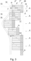
- Fig. 3 in a simplified developed view of lateral surface of the drum conveyor 8 , shows several slides 10 , with the guides 13 and the roller 14 being shown for only one slide 10 .
- the operation of the conveying apparatus 1 will be discussed with reference to a group G of the segments 4 which are placed in the conveying flutes 7 of one slide 10 ( Fig. 3 ).
- the first segment 4 is transferred from the first feeding flute 5 to the first conveying flute 7
- the second segment 4' from the second feeding flute 5' is transferred to the second conveying flute 7' , the second segment 4' being axially shifted relative to the first segment 4 .
- the next segment 4" in the next flute 5" is axially shifted relative to the second segment 4'
- the next segment 4" is shifted in a similar way.
- the segments 4 , 4' , 4" , 4′′′ placed in the successive conveying flutes 7 , 7' , 7" , 7′′′ are positioned spirally on the circumferential surface 11A of the slide drum conveyor 8 .
- the slide 10 moves in such a way that the successive segments 4 , 4" , 4" , 4′′′ move towards the axial limiter 16 and successively stop at the limiter 16 and are moved along the conveying flute 7 , then, as a result of further rotational movement of the drum conveyor 8 and the action of the cam 15 on the roller 14 , the slide 10 is withdrawn so that the groups G of the successive slides 10 line up one behind another and form a stream S of the segments 4 .
- the segments 4 , 4' , 4" , 4" are positioned in a slanting configuration in a developed view, i.e. spirally on the circumferential surface 11A .
- the segment 4′′′ abuts against the axial limiter 16
- the position c all the segments 4 , 4' , 4" , 4" are stopped by the axial limiter 16 and are held by the lateral limiter 17 , whereas the segments 4, 4" , 4" , 4′′′ are arranged in a linear configuration in developed view, i.e.
- the receiving row K1 comprises the underpressure openings 22 , which are used to hold the segments 4 immediately after receiving the segments 4 from the feeding conveyor 2 .
- the releasing row K2 comprises the underpressure openings 22 , which are used to hold the segments before transferring them to the receiving conveyor 3 .
- the receiving row K1 of the underpressure openings 22 intersects with the releasing row K2 within the first conveying flute 7 of the slide 10 .
- the receiving row K1 and the releasing row K2 may have a common underpressure opening 22 in one of the conveying flutes 7 .
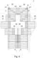
- Fig. 4 shows in a developed view the lateral surface of the drum conveyor 8 of the conveying apparatus 1' in the second embodiment which is adapted to form two streams S , S' of the segments 4 .
- the drum conveyor 8 comprises pairs of slides 10 , 10' which are shifted by means of separate mechanisms and move in opposite directions.
- the conveying apparatus 1' comprises the axial limiter 16 for the left-hand slides 10 and the axial limiter 16' for the right-hand slides 10' .
- the apparatus comprises internal axial limiters 18 , 18' for additional aligning of the streams S , S' prior to transferring the streams S , S' to the receiving conveyor 3 .
- the conveying apparatus 1' can be provided with lateral limiters 19 ,19' so that the underpressure supplied through the underpressure openings 22 can be cut off prior to transferring the segments 4 to the receiving conveyor 3 .
- the receiving row K1 of the left-hand slide 10 and the receiving row K1' of the right-hand slide 10' are situated at an angle and convergent with the conveying direction of the segments 4 .
- the receiving row K1 of the left-hand slide 10 and the receiving row K1' of the right-hand slide 10' may be situated parallel to each other.
- the releasing row K2 and the releasing row K2' are situated parallel to each other.
- Fig. 5 shows in a developed view the lateral surface of the drum conveyor 8 of the conveying apparatus 1" in the third embodiment.
- the apparatus 1" is adapted to form a single stream S of the segments 4 .
- the slide 10 is provided with six conveying flutes 7 , whereas there can be distinguished two rows K1 , K2 of the underpressure openings 22 on the slide, with the receiving row K1 intersecting with the releasing row K2 within the third conveying flute 7-3 .
- the slide 10 is shifted in the direction from right to left in the figure so that the segments 4 in the conveying flutes 7-3 , 7-4 , 7-5 , 7-6 abut against the axial limiter 16 , then the slide 10 is shifted in the direction from left to right in the drawing so that the segments 4 in the conveying flutes 7-1 , 7-2 abut against the axial limiter 18 .
- the operation of the lateral limiter 17 , 19 is the same as in the previous embodiments.
Landscapes
- Specific Conveyance Elements (AREA)
- Manufacturing Of Cigar And Cigarette Tobacco (AREA)
Abstract
Description
- The object of the invention is a conveying apparatus and a method of conveying tobacco industry segments.
- Currently, in the tobacco industry, rod-like articles which comprise a plurality of various segments put next to one another usually without gaps are manufactured, and rod-like articles with gaps between the segments are also manufactured. In this description, rod-like articles of this type will be referred to as multi-segment rods. Multi-segment rods can be manufactured by cutting a continuous rod formed by wrapping a sequence of segments on a web of wrapping material, with forming of the continuous rod taking place in a forming unit. Multi-segment rods can also be manufactured by putting segments together on drum conveyors, with streams of segments of other types being added to streams of segments of one type. The axes of symmetry of the segments are situated transversely to the direction of conveying the segments in the stream, with the stream moving along a circular path on the circumferential surface of the drum conveyor. One method of forming a stream of segments comprises cutting the rod into several segments, shifting the segments transversely to the segment axes and then axially moving the segments, the resulting stream being fed to a unit for forming sets of multiple segments. From the prior art, documents that disclose apparatuses for forming a stream of segments whose length is at least twice the diameter of the segments are known. Unfortunately, such known solutions do not work well for short segments whose length is close to their diameter. Segment alignment requires axial movement of the segments in the flutes of the drum conveyor, which is a difficult task in the case of short segments as they are unstable due to their dimensions and may rotate during movement in the flute.
- Document
US7296579B2 discloses a drum conveyor provided with slides having flutes into which rod-like articles (partial rods according to the description) are placed. When the drum conveyor is rotated, the slides move in a direction parallel to the axis of rotation, and an apparatus for aligning the rod-like articles provided with push pins causes the articles to be retained in the conveying flutes, the push pins pressing on the front surfaces of the rod-like articles. - In the tobacco industry, there is a well-known problem related to segment alignment, namely the tilting of short segments when they are moved along a flute of a drum conveyor when pressure is applied from the face. Short segments, i.e. segments whose diameter is close to the length, do not move stably and tend to rotate inside the flute, especially when the force applied to the segment is directed non-centrally at the segment face. A non-centrally directed force acting on the segment can lead to deformation, rotation and damage of the segment. Short segments should be understood as segments with a diameter of 5 to 9 mm and a length of 5 to 9 mm.
- The object of the invention is an apparatus for conveying tobacco industry segments and for forming at least one stream of the segments, comprising a drum conveyor which is provided with slides slidably mounted parallel to the axis of rotation of the drum conveyor and a mechanism for shifting the slides during the rotational movement of the drum conveyor. The slide is provided with at least two conveying flutes for conveying the segments. The conveying apparatus comprises at least one axial limiter for stopping the segment and shifting the segment along the flute during the movement of the slide in the direction opposite to the direction of movement of the slide. The apparatus according to the invention is characterised by being provided with at least one lateral limiter for holding the segment in the conveying flute from the outside when the segment is not held by the underpressure provided by underpressure openings in the conveying flute.
- Preferably, the apparatus according to the invention is characterised in that the slide is provided with a receiving row of the underpressure openings and a releasing row of the underpressure openings.
- Preferably, the apparatus according to the invention is characterised in that the receiving row of the underpressure openings and the releasing row of the underpressure openings have a common underpressure opening.
- Preferably, the apparatus according to the invention is characterised in that the receiving row of the underpressure openings is arranged spirally on the circumferential surface of the slide drum conveyor, and the releasing row of the underpressure openings is arranged circularly on the circumferential surface of the slide drum conveyor.
- Preferably, the apparatus according to the invention is characterised in that the axial limiter comprises protrusions inserted into the space of the conveying flutes of the slides.
- Preferably, the apparatus according to the invention is characterised by comprising slides arranged in pairs so that the conveying flutes of one slide in the pair are situated coaxially with the conveying flutes of the other slide.
- Preferably, the apparatus according to the invention is characterised in that the lateral limiter comprises a ring, arranged above the conveying flutes of the slides.
- Preferably, the apparatus according to the invention is characterised in that the lateral limiter has a width in the range between 0.4 and 1.6 of the length of the segment.
- Preferably, the apparatus according to the invention is characterised in that the lateral limiter has a width in the range between 4 and 15 mm, preferably between 5 and 10 mm.
- Preferably, the apparatus according to the invention is characterised in that the axial limiter comprises a cylindrical section, arranged above the conveying flutes of the slides.
- Preferably, the apparatus according to the invention is characterised in that the conveying apparatus comprises a feeding conveyor provided with discs having feeding flutes, whereas the synchronisation of the feeding flutes and the conveying flutes is provided.
- Preferably, the apparatus according to the invention is characterised in that the conveying apparatus comprises a receiving drum conveyor for receiving the stream of the segments.
- The object of the invention is also a method of conveying the segments and forming the stream of the segments in the conveying apparatus, comprising steps wherein: a group of the segments is placed on the drum conveyor by placing the segments of the group in the successive conveying flutes of the slide drum conveyor so that the segments in the adjacent conveying flutes of the slide are shifted axially to each other, the segments being held in the conveying flutes by means of the underpressure supplied to the underpressure openings. Subsequently, the slide is shifted in a direction parallel to the axis of rotation of the slide drum conveyor towards the axial limiter so that the segments in the conveying flutes successively abut with their front surface against the axial limiter. During further movement of the slide, the segments move along the conveying flute, the underpressure supplied to the underpressure openings in the conveying flutes is cut off, the segment is held in the conveying flute from the outside by the lateral limiter when the underpressure supplied to the underpressure openings is cut off. After changing the spiral configuration of all segments in the group to a circular configuration on the circumferential surface of the drum conveyor, the slide is shifted in the opposite direction, then the stream of the segments from successive groups is formed on the circumferential surface of the drum conveyor. An advantage of the invention is achieving full control over the position of the short segments during the alignment, which results in reduced downtime related to the removal of stuck segments and increased efficiency of the production line. The apparatus according to the invention does not reduce the quality of the segments.
- The object of the invention is illustrated with reference to an embodiment shown in the drawing wherein
- Fig. 1
- shows a conveying apparatus in the first embodiment,
- Figs. 2a, 2b, 2c
- show the stages of segment shifting,
- Fig. 3
- shows a developed view of a lateral surface of a slide drum conveyor,
- Fig. 4
- shows a developed view of the lateral surface of the slide drum conveyor of the conveying apparatus in the second embodiment, and
- Fig. 5
- shows a developed view of the lateral surface of the slide drum conveyor of the conveying apparatus in the third embodiment.
- The
conveying apparatus 1 for conveying tobacco industry segments and forming a stream of segments shown inFig. 1 is situated between afeeding conveyor 2 and a receivingconveyor 3. Thefeeding conveyor 2 is provided withfeeding flutes 5, whereas thefeeding conveyor 2 is adapted to deliverindividual segments 4 insuccessive feeding flutes 5. Thesegments 4 are preferably cylindrical in shape, where afront surface 4A (cylinder base) and alateral surface 4B can be distinguished. In the embodiment shown, thefeeding conveyor 2 comprises a plurality ofdiscs 6, with a plurality offeeding flutes 5 situated on a circumference of eachdisc 6. Thesegment 4 is held in thefeeding flute 5 by means of underpressure. Thesegment 4 is conveyed in theconveying apparatus 1 in a conveyingflute 7 on thedrum conveyor 8 and can be held in this flute by means of the underpressure supplied through underpressure channels to underpressure openings at the bottom of the flute. Thesegment 4 is transferred to a receiving flute 9 on the receivingconveyor 3. - The
conveying flutes 7 are spaced at equal distances from one another on the circumference of the drum conveyor 8 (in the description, the equivalent name of "slide drum conveyor" may be used instead of the name of "drum conveyor"). Theslide drum conveyor 8 is provided with a plurality ofslides 10, theslide 10 having on itsouter surface 11 at least two conveyingflutes 7, preferablyseveral conveying flutes 7. Theouter surfaces 11 of theslides 10 form jointly acircumferential surface 11A of theslide drum conveyor 8. Theslide 10 is mounted linearly slidably relative to thebody 12. Thebody 12 is rotatably mounted and has a rotation axis k, and theconveying flutes 7 are situated such that the axis m of the conveyingflute 7 is situated parallel to the rotation axis k of thebody 12. In the embodiment shown, theslide 10 is mounted onguides 13. Theslide 10 is capable of performing linear movement in a direction parallel to the rotation axis k, theslide 10 being provided with aroller 14 that works with acam 15. Thecam 15 is a cylidrical cam situated next to or within thedrum conveyor 8. The movement of theslides 10 can be performed by any other mechanism. The conveyingapparatus 1 also compriseslimiters drum conveyor 8 which are used to stop thesegments 4 in the conveyingflutes 7 or to hold the segments in the conveyingflutes 7, these limiters are discussed below. -
Figs. 2a, 2b, 2c show in cross-section the position of theslide 10 relative to thebody 12 during the rotation of theslide drum conveyor 8. Thesegment 4 is held in theflute 7 of theslide 10 by means of the underpressure supplied byunderpressure channels 20 in theslide 10 from afeed channel 21 in the body 12 (the unit supplying the underpressure to thefeed channel 21 is not shown). InFig. 2a , thesegment 4 is held by means of the underpressure supplied by twounderpressure channels 20, the segments can be held by means of moreunderpressure channels 20, whereas very short segments can be held by asingle underpressure channel 20. The underpressure openings in the conveyingflutes 7 are marked as 22. InFig. 2b , theslide 10 together with thesegment 4 moves towards theaxial limiter 16, thesegment 4 being held by the underpressure supplied by theunderpressure channels 20 or oneunderpressure channel 20. InFig. 2c , thesegment 4 is held by theaxial limiter 16 and abuts against theaxial limiter 16, i.e. theaxial limiter 16 acts on the front surface of the segment 4 (cylinder base surface), thesegment 4 is no longer held by the underpressure, thesegment 4 is held by thelateral limiter 17 acting on the lateral surface of thesegment 4. Theaxial limiter 16 and thelateral limiter 17 may be integrated, however, thelimiters axial limiter 16 may be in the form of an arc having a flat surface. Theaxial limiter 16 may be in the form of a ring, thelateral limiter 17 may be in the form of a cylindrical section. Theaxial limiter 16 may haveprotrusions 23 inserted into the space of the conveyingflutes 7. By using theprotrusions 23, the pressure exerted on thesegments 4 when thesegment 4 abuts and stops is distributed over a larger portion of thefront surface 4A of thesegment 4 than in the case of a limiter without protrusions so that thesegment 4 is not damaged. Thelateral limiter 17 may have a width d in the range between 0.4 of the length L of thesegment 4 and 1.6 of the length L of thesegment 4. Preferably, the width d is equal to the length L of thesegment 4. Preferably, the width d is equal to the length L of thesegment 4. Thelateral limiter 17 may have a width d in the range between 4 and 15 mm. Preferably, the width d of the lateral limiter is in the range between 5 and 10 mm. Theunderpressure channels 20 may have any shape, for example they may be arc-shaped. The supply of underpressure to the conveyingflute 7 may be carried out by means of a conduit with a valve which cuts off the underpressure immediately before thesegment 4 is stopped by theaxial limiter 16. Each conveyingflute 7 may be provided with a separate valve. -
Fig. 3 , in a simplified developed view of lateral surface of thedrum conveyor 8, showsseveral slides 10, with theguides 13 and theroller 14 being shown for only oneslide 10. - The operation of the conveying
apparatus 1 will be discussed with reference to a group G of thesegments 4 which are placed in the conveyingflutes 7 of one slide 10 (Fig. 3 ). Thefirst segment 4 is transferred from thefirst feeding flute 5 to the first conveyingflute 7, the second segment 4' from the second feeding flute 5' is transferred to the second conveying flute 7', the second segment 4' being axially shifted relative to thefirst segment 4. Thenext segment 4" in thenext flute 5" is axially shifted relative to the second segment 4', thenext segment 4" is shifted in a similar way. With this method of positioning, thesegments flutes circumferential surface 11A of theslide drum conveyor 8. After thesegments flutes 7, theslide 10 moves in such a way that thesuccessive segments axial limiter 16 and successively stop at thelimiter 16 and are moved along the conveyingflute 7, then, as a result of further rotational movement of thedrum conveyor 8 and the action of thecam 15 on theroller 14, theslide 10 is withdrawn so that the groups G of thesuccessive slides 10 line up one behind another and form a stream S of thesegments 4. In the position a on thedrum conveyor 8, thesegments circumferential surface 11A. In the position b, thesegment 4‴ abuts against theaxial limiter 16, in the position c, all thesegments axial limiter 16 and are held by thelateral limiter 17, whereas thesegments circumferential surface 11A of theslide drum conveyor 8, in the position d theslide 10 has started a return movement, in the positions e and f thesegments 4 form a stream S of the successive groups G. Two rows K1 and K2 of theunderpressure openings 22 can be distinguished on theslide 10. The receiving row K1 comprises theunderpressure openings 22, which are used to hold thesegments 4 immediately after receiving thesegments 4 from the feedingconveyor 2. The releasing row K2 comprises theunderpressure openings 22, which are used to hold the segments before transferring them to the receivingconveyor 3. The receiving row K1 of theunderpressure openings 22 intersects with the releasing row K2 within the first conveyingflute 7 of theslide 10. The receiving row K1 and the releasing row K2 may have a common underpressure opening 22 in one of the conveyingflutes 7. -
Fig. 4 shows in a developed view the lateral surface of thedrum conveyor 8 of the conveying apparatus 1' in the second embodiment which is adapted to form two streams S, S' of thesegments 4. Thedrum conveyor 8 comprises pairs ofslides 10, 10' which are shifted by means of separate mechanisms and move in opposite directions. The conveying apparatus 1' comprises theaxial limiter 16 for the left-hand slides 10 and the axial limiter 16' for the right-hand slides 10'. The apparatus comprises internalaxial limiters 18, 18' for additional aligning of the streams S, S' prior to transferring the streams S, S' to the receivingconveyor 3. The conveying apparatus 1' can be provided withlateral limiters 19,19' so that the underpressure supplied through theunderpressure openings 22 can be cut off prior to transferring thesegments 4 to the receivingconveyor 3. The receiving row K1 of the left-hand slide 10 and the receiving row K1' of the right-hand slide 10' are situated at an angle and convergent with the conveying direction of thesegments 4. The receiving row K1 of the left-hand slide 10 and the receiving row K1' of the right-hand slide 10' may be situated parallel to each other. The releasing row K2 and the releasing row K2' are situated parallel to each other. -
Fig. 5 shows in a developed view the lateral surface of thedrum conveyor 8 of the conveyingapparatus 1" in the third embodiment. Theapparatus 1" is adapted to form a single stream S of thesegments 4. Theslide 10 is provided with six conveyingflutes 7, whereas there can be distinguished two rows K1, K2 of theunderpressure openings 22 on the slide, with the receiving row K1 intersecting with the releasing row K2 within the third conveying flute 7-3. In order to form the stream S, theslide 10 is shifted in the direction from right to left in the figure so that thesegments 4 in the conveying flutes 7-3, 7-4, 7-5, 7-6 abut against theaxial limiter 16, then theslide 10 is shifted in the direction from left to right in the drawing so that thesegments 4 in the conveying flutes 7-1, 7-2 abut against theaxial limiter 18. The operation of thelateral limiter
Claims (13)
- An apparatus (1, 1', 1") for conveying tobacco industry segments (4) and for forming at least one stream (S) of the segments (4), comprising a drum conveyor (8) which is provided with slides (10) slidably mounted parallel to the axis of rotation (k) of the drum conveyor (8) and a mechanism for shifting the slides (10) during the rotational movement of the drum conveyor (8), the slide (10) being provided with at least two conveying flutes (7) for conveying the segments (4), the conveying apparatus (1) further comprises at least one axial limiter (16, 18) for stopping the segment (4) and shifting the segment (4) along the flute (7) during the movement of the slide (10) in the direction opposite to the direction of movement of the slide (10), characterized in that the conveying apparatus (1) is provided with at least one lateral limiter (17, 19) for holding the segment (4) in the conveying flute (7) from the outside when the segment (4) is not held by the underpressure provided by underpressure openings (22) in the conveying flute (7).
- The apparatus as in claim 1, characterised in that the slide (10) is provided with a receiving row (K1) of the underpressure openings (22) and a releasing row (K2) of the underpressure openings (22).
- The apparatus as in claim 2, characterised in that the receiving row (K1) of the underpressure openings (22) and the releasing row (K2) of the underpressure openings (22) have a common underpressure opening (22).
- The apparatus as in claim 2 or 3, characterised in that the receiving row (K1) of the underpressure openings (22) is arranged spirally on the circumferential surface (11A) of the slide drum conveyor (8), and the releasing row (K2) of the underpressure openings (22) is arranged circularly on the circumferential surface (11A) of the slide drum conveyor (8).
- The apparatus as in any of claims 1 to 4, characterised in that the axial limiter (16, 18) comprises protrusions (23) inserted into the space of the conveying flutes (7) of the slides (10).
- The apparatus as in any of claims 1 to 5, characterised by comprising slides (10, 10') arranged in pairs so that the conveying flutes (7) of one slide (10) in a pair are situated coaxially with the conveying flutes (7) of the other slide (10').
- The apparatus as in any of claims 1 to 3, characterised in that the lateral limiter (17, 19) comprises a ring, arranged above the conveying flutes (7) of the slides (10).
- The apparatus as in any of claims 1 to 7, characterised in that the lateral limiter (17, 19) has a width in the range between 0.4 and 1.6 of the length (L) of the segment (4).
- The apparatus as in any of claims 1 to 7, characterised in that the lateral limiter (17, 19) has a width in the range between 4 and 15 mm, preferably between 5 and 10 mm.
- The apparatus as in any of claims 1 to 9, characterised in that the axial limiter (16, 18) comprises a cylindrical section, arranged above the conveying flutes (7) of the slides (10).
- The apparatus as in any of claims 1 to 10, characterised in that the conveying apparatus (1) comprises a feeding conveyor (2) provided with discs (6) having feeding flutes (5), whereas the synchronisation of the feeding flutes (5) and the conveying flutes (7) is provided.
- The apparatus as in claim 1, characterised in that the conveying apparatus (1, 1', 1") comprises a receiving drum conveyor (3) for receiving the stream (S) of the segments (4).
- A method of conveying segments (4) and forming the stream (S) of the segments (4) in the conveying apparatus (1), comprising steps wherein:a group (G) of the segments (4) is placed on a drum conveyor (8) by placing the segments (4) of the group (G) in successive conveying flutes (7) of the slide drum conveyor (8) so that the segments (4) in the adjacent conveying flutes (7) of a slide (10) are shifted axially to each other, the segments (4) being held in the conveying flutes (7) by means of the underpressure supplied to the underpressure openings (22),the slide (10) is shifted in a direction parallel to the axis of rotation (k) of the slide drum conveyor (8) towards the axial limiter (16, 18) so that the segments (4) in the conveying flutes (7) successively abut with their front surface (4A) against the axial limiter (16, 18), and then, during further movement of the slide (10), the segments (4) move along the conveying flute (7),the underpressure supplied to the underpressure openings (22) in the conveying flutes (7) is cut off,the segment (4) is held in the conveying flute (7) from the outside by the lateral limiter (17, 19) when the underpressure supplied to the underpressure openings (22) is cut off,after changing the spiral configuration of all segments (4) in the group (G) to a circular configuration on the circumferential surface (11A) of the drum conveyor (8), the slide (10) is shifted in the opposite direction,the stream (S) of the segments (4) from successive groups (G) is formed on the circumferential surface of the drum conveyor (8).
Priority Applications (3)
| Application Number | Priority Date | Filing Date | Title |
|---|---|---|---|
| EP23181215.7A EP4480328B1 (en) | 2023-06-23 | 2023-06-23 | Pushing drum for the tobacco-processing industry and method for operating same |
| PL23181215.7T PL4480328T3 (en) | 2023-06-23 | 2023-06-23 | Pushing drum for the tobacco-processing industry and method for operating same |
| PCT/EP2024/067270 WO2024261141A1 (en) | 2023-06-23 | 2024-06-20 | Conveying apparatus and method of conveying tobacco industry segments |
Applications Claiming Priority (1)
| Application Number | Priority Date | Filing Date | Title |
|---|---|---|---|
| EP23181215.7A EP4480328B1 (en) | 2023-06-23 | 2023-06-23 | Pushing drum for the tobacco-processing industry and method for operating same |
Publications (2)
| Publication Number | Publication Date |
|---|---|
| EP4480328A1 true EP4480328A1 (en) | 2024-12-25 |
| EP4480328B1 EP4480328B1 (en) | 2025-11-12 |
Family
ID=87801214
Family Applications (1)
| Application Number | Title | Priority Date | Filing Date |
|---|---|---|---|
| EP23181215.7A Active EP4480328B1 (en) | 2023-06-23 | 2023-06-23 | Pushing drum for the tobacco-processing industry and method for operating same |
Country Status (3)
| Country | Link |
|---|---|
| EP (1) | EP4480328B1 (en) |
| PL (1) | PL4480328T3 (en) |
| WO (1) | WO2024261141A1 (en) |
Citations (5)
| Publication number | Priority date | Publication date | Assignee | Title |
|---|---|---|---|---|
| EP1447016A1 (en) * | 2003-02-17 | 2004-08-18 | Hauni Maschinenbau AG | Multifunctional conveyor drum |
| US20060201525A1 (en) * | 2005-03-10 | 2006-09-14 | Hauni Maschinenbau Ag | Pusher/cutter drum |
| US7296579B2 (en) | 2001-11-19 | 2007-11-20 | Focke & Co. (Gmbh & Co.) | Method and device for producing filter cigarettes |
| DE102017127593A1 (en) * | 2017-11-22 | 2019-05-23 | Hauni Maschinenbau Gmbh | Sliding drum of the tobacco processing industry |
| US20230010804A1 (en) * | 2019-12-16 | 2023-01-12 | Philip Morris Products S.A. | Method for assembling an aerosol generating article |
-
2023
- 2023-06-23 EP EP23181215.7A patent/EP4480328B1/en active Active
- 2023-06-23 PL PL23181215.7T patent/PL4480328T3/en unknown
-
2024
- 2024-06-20 WO PCT/EP2024/067270 patent/WO2024261141A1/en not_active Ceased
Patent Citations (5)
| Publication number | Priority date | Publication date | Assignee | Title |
|---|---|---|---|---|
| US7296579B2 (en) | 2001-11-19 | 2007-11-20 | Focke & Co. (Gmbh & Co.) | Method and device for producing filter cigarettes |
| EP1447016A1 (en) * | 2003-02-17 | 2004-08-18 | Hauni Maschinenbau AG | Multifunctional conveyor drum |
| US20060201525A1 (en) * | 2005-03-10 | 2006-09-14 | Hauni Maschinenbau Ag | Pusher/cutter drum |
| DE102017127593A1 (en) * | 2017-11-22 | 2019-05-23 | Hauni Maschinenbau Gmbh | Sliding drum of the tobacco processing industry |
| US20230010804A1 (en) * | 2019-12-16 | 2023-01-12 | Philip Morris Products S.A. | Method for assembling an aerosol generating article |
Also Published As
| Publication number | Publication date |
|---|---|
| WO2024261141A1 (en) | 2024-12-26 |
| EP4480328B1 (en) | 2025-11-12 |
| PL4480328T3 (en) | 2026-04-13 |
Similar Documents
| Publication | Publication Date | Title |
|---|---|---|
| US4943272A (en) | Apparatus for manufacturing cigarette filter | |
| US20040237972A1 (en) | Device for combining groups of filter segments for producing multi-segment filters of the tobacco industry, and through drum | |
| CN110228713B (en) | Conveying roller for tobacco processing industry | |
| CS252812B2 (en) | Equipment for cigarette semi-products'axial shifting | |
| EP3322309B1 (en) | Method and apparatus for shifting of rod-like articles, and apparatus of shifting of rod-like articles | |
| US9681683B2 (en) | Feeder device of products with reduced longitudinal dimensions in machines for the tobacco industry | |
| EP4480328B1 (en) | Pushing drum for the tobacco-processing industry and method for operating same | |
| KR20190074209A (en) | Apparatus for manufacturing of multi-element rods of tobacco industry | |
| US6310318B1 (en) | System for cutting glass tube into tube sections | |
| EP0654329B1 (en) | Method and device for scissor cutting strip material | |
| EP3065579B1 (en) | System and method for transferring rod-shaped articles | |
| WO2021214657A1 (en) | Method and unit for feeding rod-shaped segments | |
| US9862549B2 (en) | Transfer method and transferring apparatus for transferring rod-shaped article | |
| CN1022084C (en) | Apparatus for manufacturing cigarette filter tip | |
| WO2017036911A1 (en) | Improved apparatus for combining filter components | |
| US11213065B2 (en) | Transferring apparatus for transferring and method for transferring of rod-like articles of tobacco industry, and apparatus for conversion of configuration of a stream of such articles | |
| EP4374714A1 (en) | Feeding module for feeding segments in the form of rod-like articles, apparatus and method for manufacturing multi-segment articles | |
| US20260114499A1 (en) | Conveying and forming method and apparatus for forming a stream of tobacco industry segments | |
| EP3364782B1 (en) | Device and method for moving tubular bodies | |
| US20220061379A1 (en) | Feeding unit for feeding beads and apparatus for manufacturing rods | |
| EP4378327A1 (en) | Apparatus for manufacturing multi-segment articles | |
| RU2776519C2 (en) | Retrofitting device, instrument for manufacture of multi-segment rods and method for manufacture of multi-segment rods | |
| CA2997362C (en) | Device and method for moving tubular bodies | |
| US4324233A (en) | Feed arrangement for and method of continuously feeding cigars wrappers to cigar wrapping stations of cigar wrapping machines | |
| EP3048907B1 (en) | Feed unit for feeding products with reduced longitudinal dimensions in machines of the tobacco industry |
Legal Events
| Date | Code | Title | Description |
|---|---|---|---|
| PUAI | Public reference made under article 153(3) epc to a published international application that has entered the european phase |
Free format text: ORIGINAL CODE: 0009012 |
|
| STAA | Information on the status of an ep patent application or granted ep patent |
Free format text: STATUS: THE APPLICATION HAS BEEN PUBLISHED |
|
| AK | Designated contracting states |
Kind code of ref document: A1 Designated state(s): AL AT BE BG CH CY CZ DE DK EE ES FI FR GB GR HR HU IE IS IT LI LT LU LV MC ME MK MT NL NO PL PT RO RS SE SI SK SM TR |
|
| STAA | Information on the status of an ep patent application or granted ep patent |
Free format text: STATUS: REQUEST FOR EXAMINATION WAS MADE |
|
| 17P | Request for examination filed |
Effective date: 20250625 |
|
| GRAP | Despatch of communication of intention to grant a patent |
Free format text: ORIGINAL CODE: EPIDOSNIGR1 |
|
| STAA | Information on the status of an ep patent application or granted ep patent |
Free format text: STATUS: GRANT OF PATENT IS INTENDED |
|
| INTG | Intention to grant announced |
Effective date: 20250731 |
|
| GRAS | Grant fee paid |
Free format text: ORIGINAL CODE: EPIDOSNIGR3 |
|
| GRAA | (expected) grant |
Free format text: ORIGINAL CODE: 0009210 |
|
| STAA | Information on the status of an ep patent application or granted ep patent |
Free format text: STATUS: THE PATENT HAS BEEN GRANTED |
|
| AK | Designated contracting states |
Kind code of ref document: B1 Designated state(s): AL AT BE BG CH CY CZ DE DK EE ES FI FR GB GR HR HU IE IS IT LI LT LU LV MC ME MK MT NL NO PL PT RO RS SE SI SK SM TR |
|
| REG | Reference to a national code |
Ref country code: CH Ref legal event code: F10 Free format text: ST27 STATUS EVENT CODE: U-0-0-F10-F00 (AS PROVIDED BY THE NATIONAL OFFICE) Effective date: 20251112 Ref country code: GB Ref legal event code: FG4D |
|
| REG | Reference to a national code |
Ref country code: DE Ref legal event code: R096 Ref document number: 602023008476 Country of ref document: DE |
|
| REG | Reference to a national code |
Ref country code: IE Ref legal event code: FG4D |
|
| P01 | Opt-out of the competence of the unified patent court (upc) registered |
Free format text: CASE NUMBER: UPC_APP_0016301_4480328/2025 Effective date: 20251209 |
|
| REG | Reference to a national code |
Ref country code: NL Ref legal event code: MP Effective date: 20251112 |
|
| PG25 | Lapsed in a contracting state [announced via postgrant information from national office to epo] |
Ref country code: ES Free format text: LAPSE BECAUSE OF FAILURE TO SUBMIT A TRANSLATION OF THE DESCRIPTION OR TO PAY THE FEE WITHIN THE PRESCRIBED TIME-LIMIT Effective date: 20251112 |
|
| REG | Reference to a national code |
Ref country code: LT Ref legal event code: MG9D |
|
| PG25 | Lapsed in a contracting state [announced via postgrant information from national office to epo] |
Ref country code: NO Free format text: LAPSE BECAUSE OF FAILURE TO SUBMIT A TRANSLATION OF THE DESCRIPTION OR TO PAY THE FEE WITHIN THE PRESCRIBED TIME-LIMIT Effective date: 20260212 |
|
| PG25 | Lapsed in a contracting state [announced via postgrant information from national office to epo] |
Ref country code: HR Free format text: LAPSE BECAUSE OF FAILURE TO SUBMIT A TRANSLATION OF THE DESCRIPTION OR TO PAY THE FEE WITHIN THE PRESCRIBED TIME-LIMIT Effective date: 20251112 Ref country code: FI Free format text: LAPSE BECAUSE OF FAILURE TO SUBMIT A TRANSLATION OF THE DESCRIPTION OR TO PAY THE FEE WITHIN THE PRESCRIBED TIME-LIMIT Effective date: 20251112 Ref country code: AT Free format text: LAPSE BECAUSE OF FAILURE TO SUBMIT A TRANSLATION OF THE DESCRIPTION OR TO PAY THE FEE WITHIN THE PRESCRIBED TIME-LIMIT Effective date: 20251112 |
|
| REG | Reference to a national code |
Ref country code: AT Ref legal event code: MK05 Ref document number: 1855974 Country of ref document: AT Kind code of ref document: T Effective date: 20251112 |
|
| PG25 | Lapsed in a contracting state [announced via postgrant information from national office to epo] |
Ref country code: NL Free format text: LAPSE BECAUSE OF FAILURE TO SUBMIT A TRANSLATION OF THE DESCRIPTION OR TO PAY THE FEE WITHIN THE PRESCRIBED TIME-LIMIT Effective date: 20251112 |
|
| PG25 | Lapsed in a contracting state [announced via postgrant information from national office to epo] |
Ref country code: RS Free format text: LAPSE BECAUSE OF FAILURE TO SUBMIT A TRANSLATION OF THE DESCRIPTION OR TO PAY THE FEE WITHIN THE PRESCRIBED TIME-LIMIT Effective date: 20260212 |
|
| PG25 | Lapsed in a contracting state [announced via postgrant information from national office to epo] |
Ref country code: IS Free format text: LAPSE BECAUSE OF FAILURE TO SUBMIT A TRANSLATION OF THE DESCRIPTION OR TO PAY THE FEE WITHIN THE PRESCRIBED TIME-LIMIT Effective date: 20260312 |
|
| PG25 | Lapsed in a contracting state [announced via postgrant information from national office to epo] |
Ref country code: PT Free format text: LAPSE BECAUSE OF FAILURE TO SUBMIT A TRANSLATION OF THE DESCRIPTION OR TO PAY THE FEE WITHIN THE PRESCRIBED TIME-LIMIT Effective date: 20260312 |
|
| PG25 | Lapsed in a contracting state [announced via postgrant information from national office to epo] |
Ref country code: LV Free format text: LAPSE BECAUSE OF FAILURE TO SUBMIT A TRANSLATION OF THE DESCRIPTION OR TO PAY THE FEE WITHIN THE PRESCRIBED TIME-LIMIT Effective date: 20251112 |
|
| PG25 | Lapsed in a contracting state [announced via postgrant information from national office to epo] |
Ref country code: BG Free format text: LAPSE BECAUSE OF FAILURE TO SUBMIT A TRANSLATION OF THE DESCRIPTION OR TO PAY THE FEE WITHIN THE PRESCRIBED TIME-LIMIT Effective date: 20251112 |