EP4478738A1 - Audio processing method and apparatus, and electronic devices - Google Patents
Audio processing method and apparatus, and electronic devices Download PDFInfo
- Publication number
- EP4478738A1 EP4478738A1 EP23752390.7A EP23752390A EP4478738A1 EP 4478738 A1 EP4478738 A1 EP 4478738A1 EP 23752390 A EP23752390 A EP 23752390A EP 4478738 A1 EP4478738 A1 EP 4478738A1
- Authority
- EP
- European Patent Office
- Prior art keywords
- cover plate
- electronic device
- sound module
- device body
- connection component
- Prior art date
- Legal status (The legal status is an assumption and is not a legal conclusion. Google has not performed a legal analysis and makes no representation as to the accuracy of the status listed.)
- Granted
Links
Images



Classifications
-
- H—ELECTRICITY
- H04—ELECTRIC COMMUNICATION TECHNIQUE
- H04R—LOUDSPEAKERS, MICROPHONES, GRAMOPHONE PICK-UPS OR LIKE ACOUSTIC ELECTROMECHANICAL TRANSDUCERS; ELECTRIC HEARING AIDS; PUBLIC ADDRESS SYSTEMS
- H04R1/00—Details of transducers, loudspeakers or microphones
- H04R1/42—Combinations of transducers with fluid-pressure or other non-electrical amplifying means
-
- H—ELECTRICITY
- H04—ELECTRIC COMMUNICATION TECHNIQUE
- H04R—LOUDSPEAKERS, MICROPHONES, GRAMOPHONE PICK-UPS OR LIKE ACOUSTIC ELECTROMECHANICAL TRANSDUCERS; ELECTRIC HEARING AIDS; PUBLIC ADDRESS SYSTEMS
- H04R1/00—Details of transducers, loudspeakers or microphones
- H04R1/20—Arrangements for obtaining desired frequency or directional characteristics
- H04R1/32—Arrangements for obtaining desired frequency or directional characteristics for obtaining desired directional characteristic only
-
- A—HUMAN NECESSITIES
- A45—HAND OR TRAVELLING ARTICLES
- A45C—PURSES; LUGGAGE; HAND CARRIED BAGS
- A45C13/00—Details; Accessories
- A45C13/001—Accessories
-
- A—HUMAN NECESSITIES
- A45—HAND OR TRAVELLING ARTICLES
- A45C—PURSES; LUGGAGE; HAND CARRIED BAGS
- A45C11/00—Receptacles for purposes not provided for in groups A45C1/00-A45C9/00
- A45C11/002—Receptacles for purposes not provided for in groups A45C1/00-A45C9/00 for storing portable handheld communication devices, e.g. pagers or smart phones
-
- F—MECHANICAL ENGINEERING; LIGHTING; HEATING; WEAPONS; BLASTING
- F16—ENGINEERING ELEMENTS AND UNITS; GENERAL MEASURES FOR PRODUCING AND MAINTAINING EFFECTIVE FUNCTIONING OF MACHINES OR INSTALLATIONS; THERMAL INSULATION IN GENERAL
- F16M—FRAMES, CASINGS OR BEDS OF ENGINES, MACHINES OR APPARATUS, NOT SPECIFIC TO ENGINES, MACHINES OR APPARATUS PROVIDED FOR ELSEWHERE; STANDS; SUPPORTS
- F16M11/00—Stands or trestles as supports for apparatus or articles placed thereon ; Stands for scientific apparatus such as gravitational force meters
- F16M11/02—Heads
- F16M11/04—Means for attachment of apparatus; Means allowing adjustment of the apparatus relatively to the stand
- F16M11/06—Means for attachment of apparatus; Means allowing adjustment of the apparatus relatively to the stand allowing pivoting
- F16M11/10—Means for attachment of apparatus; Means allowing adjustment of the apparatus relatively to the stand allowing pivoting around a horizontal axis
-
- F—MECHANICAL ENGINEERING; LIGHTING; HEATING; WEAPONS; BLASTING
- F16—ENGINEERING ELEMENTS AND UNITS; GENERAL MEASURES FOR PRODUCING AND MAINTAINING EFFECTIVE FUNCTIONING OF MACHINES OR INSTALLATIONS; THERMAL INSULATION IN GENERAL
- F16M—FRAMES, CASINGS OR BEDS OF ENGINES, MACHINES OR APPARATUS, NOT SPECIFIC TO ENGINES, MACHINES OR APPARATUS PROVIDED FOR ELSEWHERE; STANDS; SUPPORTS
- F16M11/00—Stands or trestles as supports for apparatus or articles placed thereon ; Stands for scientific apparatus such as gravitational force meters
- F16M11/20—Undercarriages with or without wheels
- F16M11/2007—Undercarriages with or without wheels comprising means allowing pivoting adjustment
- F16M11/2021—Undercarriages with or without wheels comprising means allowing pivoting adjustment around a horizontal axis
- F16M11/2028—Undercarriages with or without wheels comprising means allowing pivoting adjustment around a horizontal axis for rolling, i.e. for creating a landscape-portrait rotation
-
- F—MECHANICAL ENGINEERING; LIGHTING; HEATING; WEAPONS; BLASTING
- F16—ENGINEERING ELEMENTS AND UNITS; GENERAL MEASURES FOR PRODUCING AND MAINTAINING EFFECTIVE FUNCTIONING OF MACHINES OR INSTALLATIONS; THERMAL INSULATION IN GENERAL
- F16M—FRAMES, CASINGS OR BEDS OF ENGINES, MACHINES OR APPARATUS, NOT SPECIFIC TO ENGINES, MACHINES OR APPARATUS PROVIDED FOR ELSEWHERE; STANDS; SUPPORTS
- F16M13/00—Other supports for positioning apparatus or articles; Means for steadying hand-held apparatus or articles
-
- G—PHYSICS
- G06—COMPUTING OR CALCULATING; COUNTING
- G06F—ELECTRIC DIGITAL DATA PROCESSING
- G06F1/00—Details not covered by groups G06F3/00 - G06F13/00 and G06F21/00
- G06F1/16—Constructional details or arrangements
- G06F1/1613—Constructional details or arrangements for portable computers
- G06F1/1633—Constructional details or arrangements of portable computers not specific to the type of enclosures covered by groups G06F1/1615 - G06F1/1626
- G06F1/1684—Constructional details or arrangements related to integrated I/O peripherals not covered by groups G06F1/1635 - G06F1/1675
- G06F1/1688—Constructional details or arrangements related to integrated I/O peripherals not covered by groups G06F1/1635 - G06F1/1675 the I/O peripheral being integrated loudspeakers
-
- H—ELECTRICITY
- H04—ELECTRIC COMMUNICATION TECHNIQUE
- H04M—TELEPHONIC COMMUNICATION
- H04M1/00—Substation equipment, e.g. for use by subscribers
- H04M1/02—Constructional features of telephone sets
- H04M1/0202—Portable telephone sets, e.g. cordless phones, mobile phones or bar type handsets
- H04M1/026—Details of the structure or mounting of specific components
- H04M1/0264—Details of the structure or mounting of specific components for a camera module assembly
-
- H—ELECTRICITY
- H04—ELECTRIC COMMUNICATION TECHNIQUE
- H04M—TELEPHONIC COMMUNICATION
- H04M1/00—Substation equipment, e.g. for use by subscribers
- H04M1/02—Constructional features of telephone sets
- H04M1/03—Constructional features of telephone transmitters or receivers, e.g. telephone hand-sets
-
- H—ELECTRICITY
- H04—ELECTRIC COMMUNICATION TECHNIQUE
- H04M—TELEPHONIC COMMUNICATION
- H04M1/00—Substation equipment, e.g. for use by subscribers
- H04M1/02—Constructional features of telephone sets
- H04M1/03—Constructional features of telephone transmitters or receivers, e.g. telephone hand-sets
- H04M1/035—Improving the acoustic characteristics by means of constructional features of the housing, e.g. ribs, walls, resonating chambers or cavities
-
- H—ELECTRICITY
- H04—ELECTRIC COMMUNICATION TECHNIQUE
- H04R—LOUDSPEAKERS, MICROPHONES, GRAMOPHONE PICK-UPS OR LIKE ACOUSTIC ELECTROMECHANICAL TRANSDUCERS; ELECTRIC HEARING AIDS; PUBLIC ADDRESS SYSTEMS
- H04R1/00—Details of transducers, loudspeakers or microphones
- H04R1/20—Arrangements for obtaining desired frequency or directional characteristics
- H04R1/22—Arrangements for obtaining desired frequency or directional characteristics for obtaining desired frequency characteristic only
- H04R1/28—Transducer mountings or enclosures modified by provision of mechanical or acoustic impedances, e.g. resonator, damping means
- H04R1/2807—Enclosures comprising vibrating or resonating arrangements
- H04R1/2811—Enclosures comprising vibrating or resonating arrangements for loudspeaker transducers
-
- H—ELECTRICITY
- H04—ELECTRIC COMMUNICATION TECHNIQUE
- H04R—LOUDSPEAKERS, MICROPHONES, GRAMOPHONE PICK-UPS OR LIKE ACOUSTIC ELECTROMECHANICAL TRANSDUCERS; ELECTRIC HEARING AIDS; PUBLIC ADDRESS SYSTEMS
- H04R3/00—Circuits for transducers
-
- H—ELECTRICITY
- H04—ELECTRIC COMMUNICATION TECHNIQUE
- H04R—LOUDSPEAKERS, MICROPHONES, GRAMOPHONE PICK-UPS OR LIKE ACOUSTIC ELECTROMECHANICAL TRANSDUCERS; ELECTRIC HEARING AIDS; PUBLIC ADDRESS SYSTEMS
- H04R3/00—Circuits for transducers
- H04R3/04—Circuits for transducers for correcting frequency response
-
- A—HUMAN NECESSITIES
- A45—HAND OR TRAVELLING ARTICLES
- A45C—PURSES; LUGGAGE; HAND CARRIED BAGS
- A45C2200/00—Details not otherwise provided for in A45C
- A45C2200/15—Articles convertible into a stand, e.g. for displaying purposes
-
- H—ELECTRICITY
- H04—ELECTRIC COMMUNICATION TECHNIQUE
- H04R—LOUDSPEAKERS, MICROPHONES, GRAMOPHONE PICK-UPS OR LIKE ACOUSTIC ELECTROMECHANICAL TRANSDUCERS; ELECTRIC HEARING AIDS; PUBLIC ADDRESS SYSTEMS
- H04R2430/00—Signal processing covered by H04R, not provided for in its groups
- H04R2430/01—Aspects of volume control, not necessarily automatic, in sound systems
-
- H—ELECTRICITY
- H04—ELECTRIC COMMUNICATION TECHNIQUE
- H04R—LOUDSPEAKERS, MICROPHONES, GRAMOPHONE PICK-UPS OR LIKE ACOUSTIC ELECTROMECHANICAL TRANSDUCERS; ELECTRIC HEARING AIDS; PUBLIC ADDRESS SYSTEMS
- H04R2499/00—Aspects covered by H04R or H04S not otherwise provided for in their subgroups
- H04R2499/10—General applications
- H04R2499/11—Transducers incorporated or for use in hand-held devices, e.g. mobile phones, PDA's, camera's
Definitions
- This application pertains to the field of electronic product technologies, and specifically relates to an audio processing method and apparatus and an electronic device.
- This application is intended to provide an audio processing method and apparatus and an electronic device, so as to solve the problem of electronic devices in the related art that it is difficult to balance overall appearance effect and overall space utilization.
- an embodiment of this application provides an electronic device including a device body and a decorative ring assembly, where the device body is provided with a first opening, and the decorative ring assembly is assembled onto the device body through the first opening;
- an embodiment of this application provides an audio processing method, applied to the electronic device according to the first aspect, where the electronic device includes a device body, a cover plate, and a sound module, and the method includes:
- an embodiment of this application provides an audio processing apparatus, applied to the electronic device according to the first aspect, where the electronic device includes a device body, a cover plate, and a sound module, and the apparatus includes:
- an embodiment of this application provides an electronic device.
- the electronic device includes a processor and a memory, where the memory stores a program or instructions capable of running on the processor, and when the program or instructions are executed by the processor, the steps of the method according to the second aspect are implemented.
- an embodiment of this application provides a readable storage medium, where the readable storage medium stores a program or instructions, and when the program or instructions are executed by a processor, the steps of the method according to the second aspect are implemented.
- an embodiment of this application provides a chip, where the chip includes a processor and a communication interface, the communication interface is coupled to the processor, and the processor is configured to run a program or instructions to implement the method according to the second aspect.
- an embodiment of this application provides a computer program product, where the program product is stored in a storage medium, and the program product is executed by at least one processor to implement the method according to the second aspect.
- a volume of the acoustic chamber of the sound module changes with the volume of the cavity of the expandable connection component.
- the volume of the cavity of the expandable connection component can change corresponding to the rotation angle of the cover plate, which means that the volume of the cavity of the expandable connection component changes with the rotation angle of the cover plate, so the volume of the acoustic chamber of the sound module can be adjusted by adjusting the rotation angle of the cover plate, thereby achieving the purpose of enriching the decorative ring assembly.
- the cavity of the expandable connection component communicates with the acoustic chamber of the sound module, which is equivalent that the size of the acoustic chamber of the sound module is extended, so the space of the electronic device occupied by the acoustic chamber of the sound module can be reduced. Therefore, the arrangement of the decorative ring assembly not only improves overall appearance effect of the electronic device, but also allows for expansion of the volume of the acoustic chamber of the sound module and improves space utilization of the electronic device, thereby achieving the purpose of balancing the overall appearance effect and overall space utilization of the electronic device.
- the terms “mounting”, “connection”, and “joining” should be understood in their general senses. For example, they may refer to a fixed connection, a detachable connection, or an integral connection; may refer to a mechanical connection or an electrical connection; and may refer to a direct connection, an indirect connection via an intermediate medium, or an internal communication between two elements. Persons of ordinary skill in the art can understand specific meanings of these terms in this application as appropriate to specific situations.
- the electronic device includes a device body 10 and a decorative ring assembly, where the device body 10 is provided with a first opening, and the decorative ring assembly is assembled onto the device body 10 through the first opening; and
- the volume of the acoustic chamber 111 of the sound module 11 changes with the volume of the cavity of the expandable connection component 22.
- the volume of the cavity of the expandable connection component 22 can change corresponding to the rotation angle of the cover plate 21, which means that the volume of the cavity of the expandable connection component 22 changes with the rotation angle of the cover plate 21, so the volume of the acoustic chamber 111 of the sound module 11 can be adjusted by adjusting the rotation angle of the cover plate 21, thereby achieving the purpose of enriching the decorative ring assembly.
- the cavity of the expandable connection component 22 communicates with the acoustic chamber 111 of the sound module 11, which is equivalent that the size of the acoustic chamber 111 of the sound module 11 is extended, so the space of the electronic device occupied by the acoustic chamber 111 of the sound module 11 can be reduced. Therefore, the arrangement of the decorative ring assembly not only improves overall appearance effect of the electronic device, but also allows for expansion of the volume of the acoustic chamber of the sound module 11 and improves space utilization of the electronic device, thereby achieving the purpose of balancing the overall appearance effect and overall space utilization of the electronic device.
- expanding the volume of the acoustic chamber 111 of the sound module 11 can also improve the sound effect of the sound module 11.
- the cavity of the expandable connection component 22 may communicate with a rear acoustic chamber of the sound module 11, which means that the cavity of the expandable connection component 22 can be configured to expand a volume of the rear acoustic chamber of the sound module 11.
- the volume of the cavity of the expandable connection component 22 is larger than the volume of the cavity of the expandable connection component 22 when the cover plate 21 is in a closed state, thereby increasing the rear acoustic chamber of the sound module 11.
- an audio parameter of the sound module 11 can be adjusted to reduce power consumption of the sound module 11, thereby improving endurance of the electronic device.
- expanding the volume of the rear acoustic chamber of the sound module 11 can also improve the low-frequency effect of the sound module 11 and enhance the stereo effect, thereby providing users with better audiovisual experience.
- the expandable connection component 22 has a compressed state and an expanded state, and the compressed state and expanded state of the expandable connection component 22 are associated with the rotation angle of the cover plate 21.
- the cover plate 21 can drive the expandable connection component 22 to change from the compressed state to the expanded state.
- the cover plate 21 can drive the expandable connection component 22 to change from the expanded state to the compressed state.
- volume of the cavity of the expandable connection component 22 in the compressed state is smaller than the volume of the cavity of the expandable connection component 22 in the expanded state.
- the expandable connection component 22 may be an expandable tube structure, and the cavity hermetically communicates with the acoustic chamber 111 of the sound module 11, so that the cavity functions as an extended acoustic chamber of the sound module 11.
- the device body 10 further includes a main board bracket and a circuit board, where the main board bracket is provided with a through hole, allowing the cavity of the expandable connection component 22 to communicate with the acoustic chamber 111 of the sound module 11.
- the sound module 11 further includes a circuit board and sealing foam.
- the circuit board can be electrically connected to a main board of the electronic device to implement audio output of the sound module 11.
- the sealing foam is configured to fill a gap between the circuit board and the main board bracket to improve the sealing effect of the acoustic chamber 111 of the sound module 11.
- the cover plate 21 includes a first cover plate 211 and a second cover plate 212, the first cover plate 211 corresponds to a rear camera (not shown in the figure) of the device body 10, and the second cover plate 212 corresponds to the sound module 11; and
- controlling only rotation of the second cover plate 212 corresponding to the sound module 11 can reduce a driving force for driving rotation of the second cover plate 212, and allow the first cover plate 211 to provide continuous and stable protection for the rear camera.
- the second cover plate 212 can be driven to rotate so as to drive the expandable connection component 22 to switch between the compressed state and the expanded state, thereby adjusting the volume of the acoustic chamber of the sound module 11 and achieving the purpose of improving the low-frequency effect of the sound module 11.
- the second cover plate 212 is able to switch between a closed state and an open state; and a volume of the cavity in the closed state is smaller than a volume of the cavity in the open state.
- the compressed state of the expandable connection component 22 corresponds to the closed state of the second cover plate 212
- the expanded state of the expandable connection component 22 corresponds to the open state of the second cover plate 212.
- the second cover plate 212 when the second cover plate 212 is in the open state, the second cover plate 212 is configured to support the device body 10.
- the second cover plate 212 in the open state can serve as a support foot for the device body 10, which avoids the need to arrange a separate support structure for the electronic device, allows users to view the displayed content of the electronic device in landscape mode, and effectively enriches functions of the decorative ring assembly.
- the expandable connection component 22 includes a first connecting end face connected to the second cover plate 212 and a second connecting end face connected to the sound module 11; where a cross-sectional area of the first connecting end face is larger than a cross-sectional area of the second connecting end face.
- the cross-sectional area of the first connecting end face being larger than the cross-sectional area of the second connecting end face can increase a volume increment of the expandable connection component 22 in the expanded state, thereby achieving the purpose of further increasing the volume of the acoustic chamber of the sound module 11.
- an expandable body of the expandable connection component 22 may be arranged in a tubular shape, and the first connecting end face may be hermetically connected to the second cover plate 212 by a sealant, so as to improve the sealing effect of the acoustic chamber of the sound module 11.
- the decorative ring assembly further includes a decorative ring bracket 23, the decorative ring bracket 23 is assembled onto the device body 10 through the first opening, and the first cover plate 211 is fixedly connected to the decorative ring bracket 23 and the second cover plate 212 is rotatably connected to the decorative ring bracket 23.
- the decorative ring bracket 23 is provided with a mounting groove, and the second cover plate 212 can be assembled in the mounting groove and can rotate relative to the decorative ring bracket 23 in the mounting groove.
- the decorative ring assembly further includes a fastener 24, where the fastener 24 is configured to fasten the second cover plate 212 onto the decorative ring bracket 23, so as to prevent loosening of the second cover plate 212 during flipping from affecting performance of the electronic device.
- the second cover plate 212 can be inserted from the bottom of the decorative ring bracket 23 and move upward until mounting portions on two sides of the second cover plate 212 are completely embedded into the mounting groove of the decorative ring bracket 23, and then assembled onto the decorative ring bracket 23 through the fastener 24, so as to prevent the second cover plate 212 from loosening during flipping.
- the second cover plate 212 when opened, can form a bracket of the electronic device, so that the electronic device can be placed horizontally on a desktop, allowing users to watch videos in landscape mode or perform landscape-oriented operations.
- an embodiment of this application further provides an audio processing method.
- the audio processing method can be applied to the electronic device in the foregoing embodiments, and the audio processing method includes the following steps.
- Step 701 Obtain position information of the cover plate relative to the device body.
- the position information of the cover plate relative to the device body can be obtained by a detection module such as a position sensor disposed in the electronic device, so as to determine whether the cover plate is in an open state.
- the position information of the cover plate relative to the device body can be detected by a position sensor disposed on the cover plate.
- the position sensor may be a distance sensor, a Hall sensor, or the like.
- the rotation angle of the cover plate can be detected by an angle sensor disposed on the cover plate, so as to determine the position information of the cover plate relative to the device body.
- Step 702 Adjust an audio parameter of the sound module in a case that the position information indicates that the cover plate is in an open state.
- the audio parameter of the sound module can be adjusted to improve the audio output effect of the sound module.
- the audio parameter of the sound module can be adjusted (for example, reducing audio output power of the sound module) to reduce the power consumption of the sound module, thereby improving the endurance of the electronic device.
- expanding the volume of the rear acoustic chamber of the sound module can also improve the low-frequency effect of the sound module and enhance the stereo effect, thereby providing users with better audiovisual experience.
- a control instruction can be output by a processor of the electronic device to reduce the audio output power of the sound module, thereby achieving the purpose of reducing the power consumption of the sound module.
- the position information of the cover plate relative to the device body is obtained; and the audio parameter of the sound module is adjusted in a case that the position information indicates that the cover plate is in the open state. This can improve the audio output effect of the sound module.
- the audio processing method provided in this embodiment of this application can be performed by an audio processing apparatus.
- the audio processing apparatus performing the audio processing method is used as an example to describe the audio processing apparatus provided in the embodiments of this application.
- an embodiment of this application further provides an audio processing apparatus.
- the apparatus 800 includes:
- the adjusting module 802 is specifically configured to reduce audio output power of the sound module.
- the audio processing apparatus in this embodiment of this application may be an electronic device or a component in an electronic device such as an integrated circuit or chip.
- the electronic device may be a terminal or other devices than terminals.
- the electronic device may be a mobile phone, a tablet computer, a notebook computer, a palmtop computer, an in-vehicle electronic device, a mobile internet device (Mobile Internet Device, MID), an augmented reality (augmented reality, AR) or virtual reality (virtual reality, VR) device, a robot, a wearable device, an ultra-mobile personal computer (ultra-mobile personal computer, UMPC), a netbook, a personal digital assistant (personal digital assistant, PDA), or the like, or may be a network attached storage (Network Attached Storage, NAS), a personal computer (personal computer, PC), a television (television, TV), a teller machine, a self-service machine, or the like. This is not specifically limited in the embodiments of this application.
- the audio processing apparatus in this embodiment of this application may be an apparatus having an operating system.
- the operating system may be an Android (Android) operating system, an iOS operating system, or another possible operating system. This is not specifically limited in the embodiments of this application.
- the audio processing apparatus provided in this embodiment of this application can implement the processes implemented in the method embodiment in FIG. 7 . To avoid repetition, details are not described herein again.
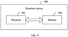
- an embodiment of this application further provides an electronic device 900 including a processor 901 and a memory 902.
- the memory 902 stores a program or instructions capable of running on the processor 901.
- the steps of the foregoing audio processing method embodiment are implemented, with the same technical effects achieved. To avoid repetition, details are not described herein again.
- the electronic device in this embodiment of this application includes the foregoing mobile electronic devices and non-mobile electronic devices.
- FIG. 10 is a structural diagram of an electronic device for implementing the embodiments of this application.
- the electronic device 1000 includes but is not limited to components such as a radio frequency unit 1001, a network module 1002, an audio output unit 1003, an input unit 1004, a sensor 1005, a display unit 1006, a user input unit 1007, an interface unit 1008, a memory 1009, and a processor 1010.
- the electronic device 1000 may further include a power supply (for example, a battery) for supplying power to the components.
- the power supply may be logically connected to the processor 1010 via a power management system, so that functions such as charge management, discharge management, and power consumption management are implemented via the power management system.
- the structure of the electronic device shown in FIG. 10 does not constitute any limitation on the electronic device.
- the electronic device may include more or fewer components than shown in the figure, or combine some of the components, or arrange the components differently. Details are not described herein.
- the processor 1010 is configured to: obtain position information of the cover plate relative to the device body; and adjust an audio parameter of the sound module in a case that the position information indicates that the cover plate is in an open state.
- the processor 1010 is configured to reduce audio output power of the sound module.
- the input unit 1004 may include a graphics processing unit (Graphics Processing Unit, GPU) 10041 and a microphone 10042.
- the graphics processing unit 10041 processes image data of a static picture or a video that is obtained by an image capture apparatus (for example, a camera) in an image capture mode or a video capture mode.
- the display unit 1006 may include a display panel 10061.
- the display panel 10061 may be configured in a form of a liquid crystal display, an organic light-emitting diode display, or the like.
- the user input unit 1007 includes at least one of a touch panel 10071 and other input devices 10072.
- the touch panel 10071 is also referred to as a touchscreen.
- the touch panel 10071 may include two parts: a touch detection apparatus and a touch controller.
- the other input devices 10072 may include but are not limited to a physical keyboard, a function button (for example, a volume control button or an on/off button), a trackball, a mouse, and a joystick. Details are not described herein.
- the memory 1009 may be configured to store software programs and various data.
- the memory 1009 may mainly include a first storage area for storing programs or instructions and a second storage area for storing data.
- the first storage area may store an operating system, an application program or instructions required by at least one function (for example, a sound play function or an image play function), and the like.
- the memory 1009 may be a volatile memory or a non-volatile memory, or the memory 1009 may include both a volatile memory and a non-volatile memory.
- the non-volatile memory may be a read-only memory (Read-Only Memory, ROM), a programmable read-only memory (Programmable ROM, PROM), an erasable programmable read-only memory (Erasable PROM, EPROM), an electrically erasable programmable read-only memory (Electrically EPROM, EEPROM), or a flash memory.
- ROM Read-Only Memory
- PROM programmable read-only memory
- Erasable PROM Erasable PROM
- EPROM electrically erasable programmable read-only memory
- EEPROM electrically erasable programmable read-only memory
- the volatile memory may be a random access memory (Random Access Memory, RAM), a static random access memory (Static RAM, SRAM), a dynamic random access memory (Dynamic RAM, DRAM), a synchronous dynamic random access memory (Synchronous DRAM, SDRAM), a double data rate synchronous dynamic random access memory (Double Data Rate SDRAM, DDRSDRAM), an enhanced synchronous dynamic random access memory (Enhanced SDRAM, ESDRAM), a synchronous link dynamic random access memory (Synch link DRAM, SLDRAM), and a direct rambus random access memory (Direct Rambus RAM, DRRAM).
- RAM Random Access Memory
- SRAM static random access memory
- DRAM dynamic random access memory
- DRAM synchronous dynamic random access memory
- SDRAM double data rate synchronous dynamic random access memory
- Enhanced SDRAM, ESDRAM enhanced synchronous dynamic random access memory
- Synch link DRAM, SLDRAM synchronous link dynamic random access memory
- Direct Rambus RAM Direct Rambus RAM
- the processor 1010 may include one or more processing units.
- the processor 1010 may integrate an application processor and a modem processor.
- the application processor primarily processes operations involving an operating system, user interface, application program, or the like.
- the modem processor primarily processes radio communication signals, for example, being a baseband processor. It can be understood that the modem processor may alternatively be not integrated in the processor 1010.
- An embodiment of this application further provides a readable storage medium.
- the readable storage medium stores a program or instructions, and when the program or instructions are executed by a processor, the processes of the foregoing audio processing method embodiment are implemented, with the same technical effects achieved. To avoid repetition, details are not described herein again.
- the processor is a processor in the electronic device in the foregoing embodiments.
- the readable storage medium includes a computer-readable storage medium such as a computer read-only memory ROM, a random access memory RAM, a magnetic disk, or an optical disc.
- An embodiment of this application further provides a chip.
- the chip includes a processor and a communication interface, where the communication interface is coupled to the processor, and the processor is configured to run a program or instructions to implement the processes of the foregoing audio processing method embodiment, with the same technical effects achieved. To avoid repetition, details are not described herein again.
- the chip mentioned in the embodiments of this application may also be referred to as a system-level chip, a system chip, a chip system, a system-on-chip, or the like.
- An embodiment of this application provides a computer program product, where the program product is stored in a storage medium.
- the program product is executed by at least one processor, the processes of the foregoing audio processing method embodiment are implemented, with the same technical effects achieved. To avoid repetition, details are not described herein again.
- the method in the foregoing embodiments can be implemented through software on a necessary general hardware platform or certainly through hardware only, but in many cases, the former is the more preferred implementation.
- the technical solutions of this application essentially or the part contributing to the prior art may be implemented in a form of a computer software product.
- the computer software product is stored in a storage medium (such as a ROM/RAM, a magnetic disk, or an optical disc), and includes several instructions for instructing a terminal (which may be a mobile phone, a computer, a server, a network device, or the like) to perform the methods described in the embodiments of this application.
Landscapes
- Engineering & Computer Science (AREA)
- Signal Processing (AREA)
- Physics & Mathematics (AREA)
- General Engineering & Computer Science (AREA)
- Acoustics & Sound (AREA)
- Mechanical Engineering (AREA)
- Computer Hardware Design (AREA)
- Theoretical Computer Science (AREA)
- Health & Medical Sciences (AREA)
- Otolaryngology (AREA)
- Human Computer Interaction (AREA)
- General Physics & Mathematics (AREA)
- Casings For Electric Apparatus (AREA)
- Circuit For Audible Band Transducer (AREA)
- Details Of Audible-Bandwidth Transducers (AREA)
Abstract
Description
- This application claims priority to
Chinese Patent Application No. 202210127948.8, filed in China on February 11, 2022 - This application pertains to the field of electronic product technologies, and specifically relates to an audio processing method and apparatus and an electronic device.
- Currently, to highlight the appearance effect of electronic devices such as mobile phones, it is common to increase the coverage area of the decorative ring around the rear camera. However, the increase in coverage area of the decorative ring around the rear camera occupies more space of the device, making it difficult for the electronic device to balance the overall appearance effect and the overall space utilization.
- It can be seen that the electronic devices in the related art have the difficulty in balancing the overall appearance effect and the overall space utilization.
- This application is intended to provide an audio processing method and apparatus and an electronic device, so as to solve the problem of electronic devices in the related art that it is difficult to balance overall appearance effect and overall space utilization.
- To solve the foregoing technical problem, this application is implemented as follows.
- According to a first aspect, an embodiment of this application provides an electronic device including a device body and a decorative ring assembly, where the device body is provided with a first opening, and the decorative ring assembly is assembled onto the device body through the first opening; and
- the decorative ring assembly includes a cover plate and an expandable connection component, where the cover plate corresponds to a sound module of the device body, the expandable connection component has a cavity, a first end of the expandable connection component is connected to the cover plate, a second end of the expandable connection component is connected to the sound module, and the cavity communicates with an acoustic chamber of the sound module; where
- the cover plate is able to rotate relative to the device body, and a volume of the cavity corresponds to a rotation angle of the cover plate.
- According to a second aspect, an embodiment of this application provides an audio processing method, applied to the electronic device according to the first aspect, where the electronic device includes a device body, a cover plate, and a sound module, and the method includes:
- obtaining position information of the cover plate relative to the device body; and
- adjusting an audio parameter of the sound module in a case that the position information indicates that the cover plate is in an open state.
- According to a third aspect, an embodiment of this application provides an audio processing apparatus, applied to the electronic device according to the first aspect, where the electronic device includes a device body, a cover plate, and a sound module, and the apparatus includes:
- an obtaining module configured to obtain position information of the cover plate relative to the device body; and
- an adjusting module configured to adjust an audio parameter of the sound module in a case that the position information indicates that the cover plate is in an open state.
- According to a fourth aspect, an embodiment of this application provides an electronic device. The electronic device includes a processor and a memory, where the memory stores a program or instructions capable of running on the processor, and when the program or instructions are executed by the processor, the steps of the method according to the second aspect are implemented.
- According to a fifth aspect, an embodiment of this application provides a readable storage medium, where the readable storage medium stores a program or instructions, and when the program or instructions are executed by a processor, the steps of the method according to the second aspect are implemented.
- According to a sixth aspect, an embodiment of this application provides a chip, where the chip includes a processor and a communication interface, the communication interface is coupled to the processor, and the processor is configured to run a program or instructions to implement the method according to the second aspect.
- According to a seventh aspect, an embodiment of this application provides a computer program product, where the program product is stored in a storage medium, and the program product is executed by at least one processor to implement the method according to the second aspect.
- In the embodiments of this application, because the cavity of the expandable connection component communicates with the acoustic chamber of the sound module, a volume of the acoustic chamber of the sound module changes with the volume of the cavity of the expandable connection component. In addition, the volume of the cavity of the expandable connection component can change corresponding to the rotation angle of the cover plate, which means that the volume of the cavity of the expandable connection component changes with the rotation angle of the cover plate, so the volume of the acoustic chamber of the sound module can be adjusted by adjusting the rotation angle of the cover plate, thereby achieving the purpose of enriching the decorative ring assembly.
- Moreover, the cavity of the expandable connection component communicates with the acoustic chamber of the sound module, which is equivalent that the size of the acoustic chamber of the sound module is extended, so the space of the electronic device occupied by the acoustic chamber of the sound module can be reduced. Therefore, the arrangement of the decorative ring assembly not only improves overall appearance effect of the electronic device, but also allows for expansion of the volume of the acoustic chamber of the sound module and improves space utilization of the electronic device, thereby achieving the purpose of balancing the overall appearance effect and overall space utilization of the electronic device.
- For additional aspects and advantages of this application, some will be given in the following description, and some will become apparent in the following description or will be understood in the practice of this application.
- The above and/or additional aspects and advantages of this application will become obvious and easy to understand from the description of the embodiments with reference to the following drawings.
-
FIG. 1 is a first schematic structural diagram of an electronic device according to an embodiment of this application; -
FIG. 2 is a second schematic structural diagram of an electronic device according to an embodiment of this application; -
FIG. 3 is a third schematic structural diagram of an electronic device according to an embodiment of this application; -
FIG. 4 is a fourth schematic structural diagram of an electronic device according to an embodiment of this application; -
FIG. 5 is a fifth schematic structural diagram of an electronic device according to an embodiment of this application; -
FIG. 6 is a sixth schematic structural diagram of an electronic device according to an embodiment of this application; -
FIG. 7 is a flowchart of an audio processing method according to an embodiment of this application; -
FIG. 8 is a structural diagram of an audio processing apparatus according to an embodiment of this application; -
FIG. 9 is a structural diagram of an electronic device according to an embodiment of this application; and -
FIG. 10 is a structural diagram of an electronic device according to another embodiment of this application. - The embodiments of this application are described in detail below. Examples of the embodiments are shown in the accompanying drawings, and reference signs that are the same or similar always indicate the same or similar elements or elements with the same or similar functions. The embodiments described below with reference to the accompanying drawings are illustrative and merely for explaining this application, and cannot be construed as any limitations on this application. All other embodiments obtained by persons of ordinary skill in the art based on the embodiments of this application without creative efforts shall fall within the protection scope of this application.
- A feature modified by the term "first" or "second" in the specification and claims of this application can explicitly or implicitly include one or more such features. In the description of this application, unless otherwise stated, "a plurality of' means two or more. In addition, in the specification and claims, "and/or" indicates at least one of the connected objects, and the character "/" generally indicates an "or" relationship between the contextually associated objects.
- In the description of this application, it should be noted that unless otherwise specified and defined explicitly, the terms "mounting", "connection", and "joining" should be understood in their general senses. For example, they may refer to a fixed connection, a detachable connection, or an integral connection; may refer to a mechanical connection or an electrical connection; and may refer to a direct connection, an indirect connection via an intermediate medium, or an internal communication between two elements. Persons of ordinary skill in the art can understand specific meanings of these terms in this application as appropriate to specific situations.
- As shown in
FIG. 1 to FIG. 6 , embodiments of this application provide an electronic device. The electronic device includes adevice body 10 and a decorative ring assembly, where thedevice body 10 is provided with a first opening, and the decorative ring assembly is assembled onto thedevice body 10 through the first opening; and - the decorative ring assembly includes a
cover plate 21 and anexpandable connection component 22, where thecover plate 21 corresponds to asound module 11 of thedevice body 10, theexpandable connection component 22 has a cavity, a first end of theexpandable connection component 22 is connected to thecover plate 21, a second end of theexpandable connection component 22 is connected to thesound module 11, and the cavity communicates with anacoustic chamber 111 of thesound module 11; where - the
cover plate 21 is able to rotate relative to thedevice body 10, and a volume of the cavity corresponds to a rotation angle of thecover plate 21. - In these embodiments, because the cavity of the
expandable connection component 22 communicates with theacoustic chamber 111 of thesound module 11, a volume of theacoustic chamber 111 of thesound module 11 changes with the volume of the cavity of theexpandable connection component 22. In addition, the volume of the cavity of theexpandable connection component 22 can change corresponding to the rotation angle of thecover plate 21, which means that the volume of the cavity of theexpandable connection component 22 changes with the rotation angle of thecover plate 21, so the volume of theacoustic chamber 111 of thesound module 11 can be adjusted by adjusting the rotation angle of thecover plate 21, thereby achieving the purpose of enriching the decorative ring assembly. - Moreover, the cavity of the
expandable connection component 22 communicates with theacoustic chamber 111 of thesound module 11, which is equivalent that the size of theacoustic chamber 111 of thesound module 11 is extended, so the space of the electronic device occupied by theacoustic chamber 111 of thesound module 11 can be reduced. Therefore, the arrangement of the decorative ring assembly not only improves overall appearance effect of the electronic device, but also allows for expansion of the volume of the acoustic chamber of thesound module 11 and improves space utilization of the electronic device, thereby achieving the purpose of balancing the overall appearance effect and overall space utilization of the electronic device. - In addition, expanding the volume of the
acoustic chamber 111 of thesound module 11 can also improve the sound effect of thesound module 11. - In some embodiments, the cavity of the
expandable connection component 22 may communicate with a rear acoustic chamber of thesound module 11, which means that the cavity of theexpandable connection component 22 can be configured to expand a volume of the rear acoustic chamber of thesound module 11. For example, when thecover plate 21 is in an open state, the volume of the cavity of theexpandable connection component 22 is larger than the volume of the cavity of theexpandable connection component 22 when thecover plate 21 is in a closed state, thereby increasing the rear acoustic chamber of thesound module 11. In this way, with the same stereo playback effect ensured, an audio parameter of thesound module 11 can be adjusted to reduce power consumption of thesound module 11, thereby improving endurance of the electronic device. In addition, expanding the volume of the rear acoustic chamber of thesound module 11 can also improve the low-frequency effect of thesound module 11 and enhance the stereo effect, thereby providing users with better audiovisual experience. - The
expandable connection component 22 has a compressed state and an expanded state, and the compressed state and expanded state of theexpandable connection component 22 are associated with the rotation angle of thecover plate 21. For example, when the rotation angle of thecover plate 21 relative to thedevice body 10 changes from small to large, thecover plate 21 can drive theexpandable connection component 22 to change from the compressed state to the expanded state. Accordingly, when the rotation angle of thecover plate 21 relative to thedevice body 10 changes from large to small, thecover plate 21 can drive theexpandable connection component 22 to change from the expanded state to the compressed state. - It can be understood that the volume of the cavity of the
expandable connection component 22 in the compressed state is smaller than the volume of the cavity of theexpandable connection component 22 in the expanded state. - The
expandable connection component 22 may be an expandable tube structure, and the cavity hermetically communicates with theacoustic chamber 111 of thesound module 11, so that the cavity functions as an extended acoustic chamber of thesound module 11. - Optionally, the
device body 10 further includes a main board bracket and a circuit board, where the main board bracket is provided with a through hole, allowing the cavity of theexpandable connection component 22 to communicate with theacoustic chamber 111 of thesound module 11. - The
sound module 11 further includes a circuit board and sealing foam. The circuit board can be electrically connected to a main board of the electronic device to implement audio output of thesound module 11. The sealing foam is configured to fill a gap between the circuit board and the main board bracket to improve the sealing effect of theacoustic chamber 111 of thesound module 11. - Optionally, the
cover plate 21 includes afirst cover plate 211 and asecond cover plate 212, thefirst cover plate 211 corresponds to a rear camera (not shown in the figure) of thedevice body 10, and thesecond cover plate 212 corresponds to thesound module 11; and - the first end of the
expandable connection component 22 is connected to thesecond cover plate 212; where - the
second cover plate 212 is able to rotate relative to thedevice body 10, and the volume of the cavity corresponds to a rotation angle of thesecond cover plate 212. - In these embodiments, controlling only rotation of the
second cover plate 212 corresponding to thesound module 11 can reduce a driving force for driving rotation of thesecond cover plate 212, and allow thefirst cover plate 211 to provide continuous and stable protection for the rear camera. - In some embodiments, the
second cover plate 212 can be driven to rotate so as to drive theexpandable connection component 22 to switch between the compressed state and the expanded state, thereby adjusting the volume of the acoustic chamber of thesound module 11 and achieving the purpose of improving the low-frequency effect of thesound module 11. - Optionally, during rotation of the
second cover plate 212, thesecond cover plate 212 is able to switch between a closed state and an open state; and
a volume of the cavity in the closed state is smaller than a volume of the cavity in the open state. - It can be understood that the compressed state of the
expandable connection component 22 corresponds to the closed state of thesecond cover plate 212, and the expanded state of theexpandable connection component 22 corresponds to the open state of thesecond cover plate 212. - Further optionally, when the
second cover plate 212 is in the open state, thesecond cover plate 212 is configured to support thedevice body 10. - In these embodiments, the
second cover plate 212 in the open state can serve as a support foot for thedevice body 10, which avoids the need to arrange a separate support structure for the electronic device, allows users to view the displayed content of the electronic device in landscape mode, and effectively enriches functions of the decorative ring assembly. - Optionally, the
expandable connection component 22 includes a first connecting end face connected to thesecond cover plate 212 and a second connecting end face connected to thesound module 11; where
a cross-sectional area of the first connecting end face is larger than a cross-sectional area of the second connecting end face. - In these embodiments, the cross-sectional area of the first connecting end face being larger than the cross-sectional area of the second connecting end face can increase a volume increment of the
expandable connection component 22 in the expanded state, thereby achieving the purpose of further increasing the volume of the acoustic chamber of thesound module 11. - In some embodiments, an expandable body of the
expandable connection component 22 may be arranged in a tubular shape, and the first connecting end face may be hermetically connected to thesecond cover plate 212 by a sealant, so as to improve the sealing effect of the acoustic chamber of thesound module 11. - Optionally, as shown in
FIG. 1 , the decorative ring assembly further includes adecorative ring bracket 23, thedecorative ring bracket 23 is assembled onto thedevice body 10 through the first opening, and thefirst cover plate 211 is fixedly connected to thedecorative ring bracket 23 and thesecond cover plate 212 is rotatably connected to thedecorative ring bracket 23. - The
decorative ring bracket 23 is provided with a mounting groove, and thesecond cover plate 212 can be assembled in the mounting groove and can rotate relative to thedecorative ring bracket 23 in the mounting groove. In addition, the decorative ring assembly further includes afastener 24, where thefastener 24 is configured to fasten thesecond cover plate 212 onto thedecorative ring bracket 23, so as to prevent loosening of thesecond cover plate 212 during flipping from affecting performance of the electronic device. - During assembling of the decorative ring assembly, the
second cover plate 212 can be inserted from the bottom of thedecorative ring bracket 23 and move upward until mounting portions on two sides of thesecond cover plate 212 are completely embedded into the mounting groove of thedecorative ring bracket 23, and then assembled onto thedecorative ring bracket 23 through thefastener 24, so as to prevent thesecond cover plate 212 from loosening during flipping. - As shown in
FIG. 6 , when opened, thesecond cover plate 212 can form a bracket of the electronic device, so that the electronic device can be placed horizontally on a desktop, allowing users to watch videos in landscape mode or perform landscape-oriented operations. - As shown in
FIG. 7 , an embodiment of this application further provides an audio processing method. The audio processing method can be applied to the electronic device in the foregoing embodiments, and the audio processing method includes the following steps. - Step 701: Obtain position information of the cover plate relative to the device body.
- In this step, the position information of the cover plate relative to the device body can be obtained by a detection module such as a position sensor disposed in the electronic device, so as to determine whether the cover plate is in an open state.
- In some embodiments, the position information of the cover plate relative to the device body can be detected by a position sensor disposed on the cover plate.
- Specifically, the position sensor may be a distance sensor, a Hall sensor, or the like.
- In some other embodiments, the rotation angle of the cover plate can be detected by an angle sensor disposed on the cover plate, so as to determine the position information of the cover plate relative to the device body.
- Step 702: Adjust an audio parameter of the sound module in a case that the position information indicates that the cover plate is in an open state.
- In this step, in a case that the detected position information indicates that the cover plate is in the open state, that is, in a case that the volume of the acoustic chamber of the sound module is effectively extended, the audio parameter of the sound module can be adjusted to improve the audio output effect of the sound module.
- For example, in a case that the detected position information indicates that the cover plate is in the open state, with the same stereo playback effect ensured, the audio parameter of the sound module can be adjusted (for example, reducing audio output power of the sound module) to reduce the power consumption of the sound module, thereby improving the endurance of the electronic device. In addition, expanding the volume of the rear acoustic chamber of the sound module can also improve the low-frequency effect of the sound module and enhance the stereo effect, thereby providing users with better audiovisual experience.
- In some embodiments, a control instruction can be output by a processor of the electronic device to reduce the audio output power of the sound module, thereby achieving the purpose of reducing the power consumption of the sound module.
- It should be noted that the implementations of the electronic device are also applicable to the embodiment of the audio processing method, with the same technical effects achieved. Details are not described herein again.
- According to the audio processing method provided in this embodiment of this application, the position information of the cover plate relative to the device body is obtained; and the audio parameter of the sound module is adjusted in a case that the position information indicates that the cover plate is in the open state. This can improve the audio output effect of the sound module.
- The audio processing method provided in this embodiment of this application can be performed by an audio processing apparatus. In the embodiments of this application, the audio processing apparatus performing the audio processing method is used as an example to describe the audio processing apparatus provided in the embodiments of this application.
- As shown in
FIG. 8 , an embodiment of this application further provides an audio processing apparatus. Theapparatus 800 includes: - an obtaining
module 801 configured to obtain position information of the cover plate relative to the device body; and - an
adjusting module 802 configured to adjust an audio parameter of the sound module in a case that the position information indicates that the cover plate is in an open state. - Optionally, the adjusting
module 802 is specifically configured to reduce audio output power of the sound module. - The audio processing apparatus in this embodiment of this application may be an electronic device or a component in an electronic device such as an integrated circuit or chip. The electronic device may be a terminal or other devices than terminals. For example, the electronic device may be a mobile phone, a tablet computer, a notebook computer, a palmtop computer, an in-vehicle electronic device, a mobile internet device (Mobile Internet Device, MID), an augmented reality (augmented reality, AR) or virtual reality (virtual reality, VR) device, a robot, a wearable device, an ultra-mobile personal computer (ultra-mobile personal computer, UMPC), a netbook, a personal digital assistant (personal digital assistant, PDA), or the like, or may be a network attached storage (Network Attached Storage, NAS), a personal computer (personal computer, PC), a television (television, TV), a teller machine, a self-service machine, or the like. This is not specifically limited in the embodiments of this application.
- The audio processing apparatus in this embodiment of this application may be an apparatus having an operating system. The operating system may be an Android (Android) operating system, an iOS operating system, or another possible operating system. This is not specifically limited in the embodiments of this application.
- The audio processing apparatus provided in this embodiment of this application can implement the processes implemented in the method embodiment in
FIG. 7 . To avoid repetition, details are not described herein again. - Optionally, as shown in
FIG. 9 , an embodiment of this application further provides anelectronic device 900 including aprocessor 901 and amemory 902. Thememory 902 stores a program or instructions capable of running on theprocessor 901. When the program or instructions are executed by theprocessor 901, the steps of the foregoing audio processing method embodiment are implemented, with the same technical effects achieved. To avoid repetition, details are not described herein again. - It should be noted that the electronic device in this embodiment of this application includes the foregoing mobile electronic devices and non-mobile electronic devices.
-
FIG. 10 is a structural diagram of an electronic device for implementing the embodiments of this application. - The
electronic device 1000 includes but is not limited to components such as aradio frequency unit 1001, anetwork module 1002, anaudio output unit 1003, an input unit 1004, asensor 1005, adisplay unit 1006, a user input unit 1007, aninterface unit 1008, amemory 1009, and aprocessor 1010. - Persons skilled in the art can understand that the
electronic device 1000 may further include a power supply (for example, a battery) for supplying power to the components. The power supply may be logically connected to theprocessor 1010 via a power management system, so that functions such as charge management, discharge management, and power consumption management are implemented via the power management system. The structure of the electronic device shown inFIG. 10 does not constitute any limitation on the electronic device. The electronic device may include more or fewer components than shown in the figure, or combine some of the components, or arrange the components differently. Details are not described herein. - The
processor 1010 is configured to: obtain position information of the cover plate relative to the device body; and adjust an audio parameter of the sound module in a case that the position information indicates that the cover plate is in an open state. - Optionally, the
processor 1010 is configured to reduce audio output power of the sound module. - It should be understood that in the embodiments of this application, the input unit 1004 may include a graphics processing unit (Graphics Processing Unit, GPU) 10041 and a
microphone 10042. Thegraphics processing unit 10041 processes image data of a static picture or a video that is obtained by an image capture apparatus (for example, a camera) in an image capture mode or a video capture mode. Thedisplay unit 1006 may include adisplay panel 10061. Thedisplay panel 10061 may be configured in a form of a liquid crystal display, an organic light-emitting diode display, or the like. The user input unit 1007 includes at least one of atouch panel 10071 andother input devices 10072. Thetouch panel 10071 is also referred to as a touchscreen. Thetouch panel 10071 may include two parts: a touch detection apparatus and a touch controller. Theother input devices 10072 may include but are not limited to a physical keyboard, a function button (for example, a volume control button or an on/off button), a trackball, a mouse, and a joystick. Details are not described herein. - The
memory 1009 may be configured to store software programs and various data. Thememory 1009 may mainly include a first storage area for storing programs or instructions and a second storage area for storing data. The first storage area may store an operating system, an application program or instructions required by at least one function (for example, a sound play function or an image play function), and the like. Additionally, thememory 1009 may be a volatile memory or a non-volatile memory, or thememory 1009 may include both a volatile memory and a non-volatile memory. The non-volatile memory may be a read-only memory (Read-Only Memory, ROM), a programmable read-only memory (Programmable ROM, PROM), an erasable programmable read-only memory (Erasable PROM, EPROM), an electrically erasable programmable read-only memory (Electrically EPROM, EEPROM), or a flash memory. The volatile memory may be a random access memory (Random Access Memory, RAM), a static random access memory (Static RAM, SRAM), a dynamic random access memory (Dynamic RAM, DRAM), a synchronous dynamic random access memory (Synchronous DRAM, SDRAM), a double data rate synchronous dynamic random access memory (Double Data Rate SDRAM, DDRSDRAM), an enhanced synchronous dynamic random access memory (Enhanced SDRAM, ESDRAM), a synchronous link dynamic random access memory (Synch link DRAM, SLDRAM), and a direct rambus random access memory (Direct Rambus RAM, DRRAM). Thememory 1009 in the embodiments of this application includes but is not be limited to these and any other applicable types of memories. - The
processor 1010 may include one or more processing units. Optionally, theprocessor 1010 may integrate an application processor and a modem processor. The application processor primarily processes operations involving an operating system, user interface, application program, or the like. The modem processor primarily processes radio communication signals, for example, being a baseband processor. It can be understood that the modem processor may alternatively be not integrated in theprocessor 1010. - An embodiment of this application further provides a readable storage medium. The readable storage medium stores a program or instructions, and when the program or instructions are executed by a processor, the processes of the foregoing audio processing method embodiment are implemented, with the same technical effects achieved. To avoid repetition, details are not described herein again.
- The processor is a processor in the electronic device in the foregoing embodiments. The readable storage medium includes a computer-readable storage medium such as a computer read-only memory ROM, a random access memory RAM, a magnetic disk, or an optical disc.
- An embodiment of this application further provides a chip. The chip includes a processor and a communication interface, where the communication interface is coupled to the processor, and the processor is configured to run a program or instructions to implement the processes of the foregoing audio processing method embodiment, with the same technical effects achieved. To avoid repetition, details are not described herein again.
- It should be understood that the chip mentioned in the embodiments of this application may also be referred to as a system-level chip, a system chip, a chip system, a system-on-chip, or the like.
- An embodiment of this application provides a computer program product, where the program product is stored in a storage medium. When the program product is executed by at least one processor, the processes of the foregoing audio processing method embodiment are implemented, with the same technical effects achieved. To avoid repetition, details are not described herein again.
- It should be noted that in this specification, the terms "include", "comprise", or any of their variants are intended to cover a non-exclusive inclusion, such that a process, method, article, or apparatus that includes a series of elements includes not only those elements but also other elements that are not expressly listed, or further includes elements inherent to such process, method, article, or apparatus. Without more restrictions, an element preceded by the statement "includes a..." does not preclude the presence of other identical elements in the process, method, article, or apparatus that includes the element. In addition, it should be noted that the scope of the method and apparatus in the embodiments of this application is not limited to functions being performed in the order shown or discussed, but may further include functions being performed at substantially the same time or in a reverse order, depending on the functions involved. For example, the described method may be performed in an order different from the order described, and steps may be added, omitted, or combined. In addition, features described with reference to some examples may be combined in other examples.
- Based on the foregoing description of the embodiments, persons skilled in the art can clearly understand that the method in the foregoing embodiments can be implemented through software on a necessary general hardware platform or certainly through hardware only, but in many cases, the former is the more preferred implementation. Based on such an understanding, the technical solutions of this application essentially or the part contributing to the prior art may be implemented in a form of a computer software product. The computer software product is stored in a storage medium (such as a ROM/RAM, a magnetic disk, or an optical disc), and includes several instructions for instructing a terminal (which may be a mobile phone, a computer, a server, a network device, or the like) to perform the methods described in the embodiments of this application.
- The foregoing describes the embodiments of this application with reference to the accompanying drawings. However, this application is not limited to the foregoing specific implementations. These specific implementations are merely illustrative rather than restrictive. Inspired by this application, persons of ordinary skill in the art may develop many other forms without departing from the essence of this application and the protection scope of the claims, and all such forms shall fall within the protection scope of this application.
Claims (14)
- An electronic device, comprising a device body and a decorative ring assembly, wherein the device body is provided with a first opening, and the decorative ring assembly is assembled onto the device body through the first opening; andthe decorative ring assembly comprises a cover plate and an expandable connection component, wherein the cover plate corresponds to a sound module of the device body, the expandable connection component has a cavity, a first end of the expandable connection component is connected to the cover plate, a second end of the expandable connection component is connected to the sound module, and the cavity communicates with an acoustic chamber of the sound module; whereinthe cover plate is able to rotate relative to the device body, and a volume of the cavity corresponds to a rotation angle of the cover plate.
- The electronic device according to claim 1, wherein the cover plate comprises a first cover plate and a second cover plate, the first cover plate corresponds to a rear camera of the device body, and the second cover plate corresponds to the sound module; andthe first end of the expandable connection component is connected to the second cover plate; whereinthe second cover plate is able to rotate relative to the device body, and the volume of the cavity corresponds to a rotation angle of the second cover plate.
- The electronic device according to claim 2, wherein during rotation of the second cover plate, the second cover plate is able to switch between a closed state and an open state; and
a volume of the cavity in the closed state is smaller than a volume of the cavity in the open state. - The electronic device according to claim 3, wherein the expandable connection component comprises a first connecting end face connected to the second cover plate and a second connecting end face connected to the sound module; wherein
a cross-sectional area of the first connecting end face is larger than a cross-sectional area of the second connecting end face. - The electronic device according to claim 4, wherein an expandable body of the expandable connection component is arranged in a tubular shape, and the first connecting end face is hermetically connected to the second cover plate by a sealant.
- The electronic device according to any one of claims 2 to 5, wherein the decorative ring assembly further comprises a decorative ring bracket, the decorative ring bracket is assembled onto the device body through the first opening, and the first cover plate is fixedly connected to the decorative ring bracket and the second cover plate is rotatably connected to the decorative ring bracket.
- An audio processing method, applied to the electronic device according to any one of claims 1 to 6, wherein the electronic device comprises a device body, a cover plate, and a sound module, and the method comprises:obtaining position information of the cover plate relative to the device body; andadjusting an audio parameter of the sound module in a case that the position information indicates that the cover plate is in an open state.
- The method according to claim 7, wherein the audio parameter is audio output power, and the adjusting an audio parameter of the sound module comprises:
reducing the audio output power of the sound module. - An audio processing apparatus, applied to the electronic device according to any one of claims 1 to 6, wherein the electronic device comprises a device body, a cover plate, and a sound module, and the apparatus comprises:an obtaining module configured to obtain position information of the cover plate relative to the device body; andan adjusting module configured to adjust an audio parameter of the sound module in a case that the position information indicates that the cover plate is in an open state.
- An electronic device, comprising a processor and a memory, wherein the memory stores a program or instructions capable of running on the processor, and when the program or instructions are executed by the processor, the steps of the audio processing method according to claim 7 or 8 are implemented.
- A readable storage medium, wherein the readable storage medium stores a program or instructions, and when the program or instructions are executed by a processor, the steps of the audio processing method according to claim 7 or 8 are implemented.
- A computer program product, wherein the program product is stored in a non-volatile storage medium, and the program product is executed by at least one processor to implement the steps of the audio processing method according to claim 7 or 8.
- A chip, wherein the chip comprises a processor and a communication interface, the communication interface is coupled to the processor, and the processor is configured to run a program or instructions to implement the steps of the audio processing method according to claim 7 or 8.
- An electronic device, configured to perform the steps of the audio processing method according to claim 7 or 8.
Applications Claiming Priority (2)
| Application Number | Priority Date | Filing Date | Title |
|---|---|---|---|
| CN202210127948.8A CN114501227B (en) | 2022-02-11 | 2022-02-11 | Audio processing method and device and electronic equipment |
| PCT/CN2023/075127 WO2023151610A1 (en) | 2022-02-11 | 2023-02-09 | Audio processing method and apparatus, and electronic devices |
Publications (3)
| Publication Number | Publication Date |
|---|---|
| EP4478738A1 true EP4478738A1 (en) | 2024-12-18 |
| EP4478738A4 EP4478738A4 (en) | 2025-06-11 |
| EP4478738B1 EP4478738B1 (en) | 2025-12-24 |
Family
ID=81481355
Family Applications (1)
| Application Number | Title | Priority Date | Filing Date |
|---|---|---|---|
| EP23752390.7A Active EP4478738B1 (en) | 2022-02-11 | 2023-02-09 | Audio processing method and apparatus, and electronic devices |
Country Status (5)
| Country | Link |
|---|---|
| US (1) | US20240406620A1 (en) |
| EP (1) | EP4478738B1 (en) |
| CN (1) | CN114501227B (en) |
| ES (1) | ES3059157T3 (en) |
| WO (1) | WO2023151610A1 (en) |
Families Citing this family (1)
| Publication number | Priority date | Publication date | Assignee | Title |
|---|---|---|---|---|
| CN114501227B (en) * | 2022-02-11 | 2023-11-03 | 维沃移动通信有限公司 | Audio processing method and device and electronic equipment |
Family Cites Families (14)
| Publication number | Priority date | Publication date | Assignee | Title |
|---|---|---|---|---|
| US6292573B1 (en) * | 1999-09-30 | 2001-09-18 | Motorola, Inc. | Portable communication device with collapsible speaker enclosure |
| JP2001169376A (en) * | 1999-12-08 | 2001-06-22 | Matsushita Electric Ind Co Ltd | Sound equipment |
| JP2003323230A (en) * | 2002-04-30 | 2003-11-14 | Kenwood Corp | Notebook sized personal computer and its loudspeaker system |
| US20050253957A1 (en) * | 2004-05-13 | 2005-11-17 | Stefan Gustavsson | Mobile electronic apparatus with camera that takes pictures through lens in speaker |
| US7350618B2 (en) * | 2005-04-01 | 2008-04-01 | Creative Technology Ltd | Multimedia speaker product |
| CN101895802A (en) * | 2010-06-11 | 2010-11-24 | 青岛海信移动通信技术股份有限公司 | Mobile terminal equipment |
| CN103179487A (en) * | 2011-12-23 | 2013-06-26 | 联想(北京)有限公司 | Sound box device and electronic terminal |
| CN205581714U (en) * | 2016-03-15 | 2016-09-14 | 合肥联宝信息技术有限公司 | Telescopic notebook computer audio amplifier and be provided with notebook computer of this audio amplifier |
| CN210327668U (en) * | 2019-11-14 | 2020-04-14 | 哈尔滨理工大学 | Smartphones in daily life of patients with chronic diseases |
| US11044548B2 (en) * | 2019-12-26 | 2021-06-22 | Intel Corporation | Dynamic speaker chamber |
| CN112398986A (en) * | 2020-11-16 | 2021-02-23 | Oppo广东移动通信有限公司 | Electronic equipment |
| CN113225629B (en) * | 2021-03-10 | 2022-09-09 | 深圳市优特杰科技有限公司 | Internet intelligence audio amplifier with from adsorption function |
| CN113286025B (en) * | 2021-05-24 | 2022-12-06 | 维沃移动通信有限公司 | Electronic equipment, audio parameter adjusting method and device |
| CN114501227B (en) * | 2022-02-11 | 2023-11-03 | 维沃移动通信有限公司 | Audio processing method and device and electronic equipment |
-
2022
- 2022-02-11 CN CN202210127948.8A patent/CN114501227B/en active Active
-
2023
- 2023-02-09 EP EP23752390.7A patent/EP4478738B1/en active Active
- 2023-02-09 ES ES23752390T patent/ES3059157T3/en active Active
- 2023-02-09 WO PCT/CN2023/075127 patent/WO2023151610A1/en not_active Ceased
-
2024
- 2024-08-12 US US18/800,298 patent/US20240406620A1/en active Pending
Also Published As
| Publication number | Publication date |
|---|---|
| CN114501227A (en) | 2022-05-13 |
| ES3059157T3 (en) | 2026-03-19 |
| EP4478738A4 (en) | 2025-06-11 |
| WO2023151610A1 (en) | 2023-08-17 |
| CN114501227B (en) | 2023-11-03 |
| EP4478738B1 (en) | 2025-12-24 |
| US20240406620A1 (en) | 2024-12-05 |
Similar Documents
| Publication | Publication Date | Title |
|---|---|---|
| US20220279666A1 (en) | Electronic device including flexible display and method for controlling same | |
| TWI823974B (en) | Information handling system (ihs), its method of operation, and hardware memory device | |
| US10942558B2 (en) | User interface adaptation based on detected user location | |
| CN103238146B (en) | smart board orientation | |
| CN102754067B (en) | For comprising the data manipulation method of the terminal of three display units and supporting the terminal of described method | |
| WO2024041047A1 (en) | Screen refresh rate switching method and electronic device | |
| CN112328008B (en) | Display screen control method and device and electronic equipment | |
| EP4495922A1 (en) | Display control chip, display panel, and related device, method and apparatus | |
| EP4047464A1 (en) | Screenshot display method and apparatus, and terminal device | |
| US20240406620A1 (en) | Audio processing method and apparatus and electronic device | |
| EP3846016B1 (en) | Image display method and mobile terminal | |
| CN110187822A (en) | A kind of terminal and the control method for screen display applied to terminal | |
| CN116486745A (en) | Display control method, device and electronic equipment | |
| CN110865758A (en) | A display method and electronic device | |
| US20250231780A1 (en) | Background Application Management Method, Electronic Device and Non-Transitory Readable Storage Medium | |
| WO2021017705A1 (en) | Interface display method and terminal device | |
| CN109669514B (en) | A terminal control method and terminal | |
| JP2010183154A (en) | Terminal unit and program | |
| CN118301420A (en) | Media resource combined stream playing method and device, electronic equipment and storage medium | |
| EP4470454A1 (en) | Blood pressure measurement method, apparatus, and electronic device | |
| CN110751931B (en) | Page refreshing method and device for ink screen | |
| EP4130997B1 (en) | Display control method and system, mobile terminal, and storage medium | |
| US20110102350A1 (en) | Method for controlling operations according to mechanical touching actions and portable electronic device adapted to the same | |
| US20250246108A1 (en) | Display method of electronic device, electronic device, and apparatus | |
| US20220198991A1 (en) | Display apparatus and display method for display apparatus with rotatable display |
Legal Events
| Date | Code | Title | Description |
|---|---|---|---|
| STAA | Information on the status of an ep patent application or granted ep patent |
Free format text: STATUS: THE INTERNATIONAL PUBLICATION HAS BEEN MADE |
|
| PUAI | Public reference made under article 153(3) epc to a published international application that has entered the european phase |
Free format text: ORIGINAL CODE: 0009012 |
|
| STAA | Information on the status of an ep patent application or granted ep patent |
Free format text: STATUS: REQUEST FOR EXAMINATION WAS MADE |
|
| 17P | Request for examination filed |
Effective date: 20240816 |
|
| AK | Designated contracting states |
Kind code of ref document: A1 Designated state(s): AL AT BE BG CH CY CZ DE DK EE ES FI FR GB GR HR HU IE IS IT LI LT LU LV MC ME MK MT NL NO PL PT RO RS SE SI SK SM TR |
|
| REG | Reference to a national code |
Ref legal event code: R079 Free format text: PREVIOUS MAIN CLASS: H04R0001320000 Ipc: A45C0013000000 Ref country code: DE Ref legal event code: R079 Ref document number: 602023010175 Country of ref document: DE Free format text: PREVIOUS MAIN CLASS: H04R0001320000 Ipc: A45C0013000000 |
|
| DAV | Request for validation of the european patent (deleted) | ||
| DAX | Request for extension of the european patent (deleted) | ||
| A4 | Supplementary search report drawn up and despatched |
Effective date: 20250512 |
|
| RIC1 | Information provided on ipc code assigned before grant |
Ipc: H04M 1/03 20060101ALI20250506BHEP Ipc: F16M 11/10 20060101ALI20250506BHEP Ipc: H04R 3/04 20060101ALI20250506BHEP Ipc: H04R 1/28 20060101ALI20250506BHEP Ipc: H04M 1/02 20060101ALI20250506BHEP Ipc: F16M 13/00 20060101ALI20250506BHEP Ipc: A45C 11/00 20060101ALI20250506BHEP Ipc: G06F 1/16 20060101ALI20250506BHEP Ipc: H04R 1/32 20060101ALI20250506BHEP Ipc: A45C 13/00 20060101AFI20250506BHEP |
|
| GRAP | Despatch of communication of intention to grant a patent |
Free format text: ORIGINAL CODE: EPIDOSNIGR1 |
|
| STAA | Information on the status of an ep patent application or granted ep patent |
Free format text: STATUS: GRANT OF PATENT IS INTENDED |
|
| INTG | Intention to grant announced |
Effective date: 20251010 |
|
| GRAS | Grant fee paid |
Free format text: ORIGINAL CODE: EPIDOSNIGR3 |
|
| GRAA | (expected) grant |
Free format text: ORIGINAL CODE: 0009210 |
|
| STAA | Information on the status of an ep patent application or granted ep patent |
Free format text: STATUS: THE PATENT HAS BEEN GRANTED |
|
| AK | Designated contracting states |
Kind code of ref document: B1 Designated state(s): AL AT BE BG CH CY CZ DE DK EE ES FI FR GB GR HR HU IE IS IT LI LT LU LV MC ME MK MT NL NO PL PT RO RS SE SI SK SM TR |
|
| REG | Reference to a national code |
Ref country code: CH Ref legal event code: F10 Free format text: ST27 STATUS EVENT CODE: U-0-0-F10-F00 (AS PROVIDED BY THE NATIONAL OFFICE) Effective date: 20251224 Ref country code: GB Ref legal event code: FG4D |
|
| REG | Reference to a national code |
Ref country code: DE Ref legal event code: R096 Ref document number: 602023010175 Country of ref document: DE |
|
| PGFP | Annual fee paid to national office [announced via postgrant information from national office to epo] |
Ref country code: FR Payment date: 20251231 Year of fee payment: 4 |
|
| REG | Reference to a national code |
Ref country code: NL Ref legal event code: FP |
|
| PGFP | Annual fee paid to national office [announced via postgrant information from national office to epo] |
Ref country code: NL Payment date: 20260106 Year of fee payment: 4 |
|
| REG | Reference to a national code |
Ref country code: ES Ref legal event code: FG2A Ref document number: 3059157 Country of ref document: ES Kind code of ref document: T3 Effective date: 20260319 |
|
| PGFP | Annual fee paid to national office [announced via postgrant information from national office to epo] |
Ref country code: ES Payment date: 20260305 Year of fee payment: 4 |
|
| REG | Reference to a national code |
Ref country code: LT Ref legal event code: MG9D |
|
| PG25 | Lapsed in a contracting state [announced via postgrant information from national office to epo] |
Ref country code: NO Free format text: LAPSE BECAUSE OF FAILURE TO SUBMIT A TRANSLATION OF THE DESCRIPTION OR TO PAY THE FEE WITHIN THE PRESCRIBED TIME-LIMIT Effective date: 20260324 |
|
| PGFP | Annual fee paid to national office [announced via postgrant information from national office to epo] |
Ref country code: DE Payment date: 20251230 Year of fee payment: 4 |
|
| PG25 | Lapsed in a contracting state [announced via postgrant information from national office to epo] |
Ref country code: FI Free format text: LAPSE BECAUSE OF FAILURE TO SUBMIT A TRANSLATION OF THE DESCRIPTION OR TO PAY THE FEE WITHIN THE PRESCRIBED TIME-LIMIT Effective date: 20251224 Ref country code: HR Free format text: LAPSE BECAUSE OF FAILURE TO SUBMIT A TRANSLATION OF THE DESCRIPTION OR TO PAY THE FEE WITHIN THE PRESCRIBED TIME-LIMIT Effective date: 20251224 |
|
| PGFP | Annual fee paid to national office [announced via postgrant information from national office to epo] |
Ref country code: AT Payment date: 20260301 Year of fee payment: 4 |
|
| PGFP | Annual fee paid to national office [announced via postgrant information from national office to epo] |
Ref country code: IT Payment date: 20260228 Year of fee payment: 4 |
|
| PG25 | Lapsed in a contracting state [announced via postgrant information from national office to epo] |
Ref country code: RS Free format text: LAPSE BECAUSE OF FAILURE TO SUBMIT A TRANSLATION OF THE DESCRIPTION OR TO PAY THE FEE WITHIN THE PRESCRIBED TIME-LIMIT Effective date: 20260324 |
|
| PG25 | Lapsed in a contracting state [announced via postgrant information from national office to epo] |
Ref country code: LV Free format text: LAPSE BECAUSE OF FAILURE TO SUBMIT A TRANSLATION OF THE DESCRIPTION OR TO PAY THE FEE WITHIN THE PRESCRIBED TIME-LIMIT Effective date: 20251224 |
|
| PG25 | Lapsed in a contracting state [announced via postgrant information from national office to epo] |
Ref country code: BG Free format text: LAPSE BECAUSE OF FAILURE TO SUBMIT A TRANSLATION OF THE DESCRIPTION OR TO PAY THE FEE WITHIN THE PRESCRIBED TIME-LIMIT Effective date: 20251224 |