EP4478626A2 - 4tx codebook enhancement in lte - Google Patents
4tx codebook enhancement in lte Download PDFInfo
- Publication number
- EP4478626A2 EP4478626A2 EP24183974.5A EP24183974A EP4478626A2 EP 4478626 A2 EP4478626 A2 EP 4478626A2 EP 24183974 A EP24183974 A EP 24183974A EP 4478626 A2 EP4478626 A2 EP 4478626A2
- Authority
- EP
- European Patent Office
- Prior art keywords
- codebook
- matrix
- mod
- rank
- precoding matrix
- Prior art date
- Legal status (The legal status is an assumption and is not a legal conclusion. Google has not performed a legal analysis and makes no representation as to the accuracy of the status listed.)
- Pending
Links
Images



Classifications
-
- H—ELECTRICITY
- H04—ELECTRIC COMMUNICATION TECHNIQUE
- H04B—TRANSMISSION
- H04B7/00—Radio transmission systems, i.e. using radiation field
- H04B7/02—Diversity systems; Multi-antenna system, i.e. transmission or reception using multiple antennas
- H04B7/04—Diversity systems; Multi-antenna system, i.e. transmission or reception using multiple antennas using two or more spaced independent antennas
- H04B7/0413—MIMO systems
- H04B7/0456—Selection of precoding matrices or codebooks, e.g. using matrices antenna weighting
-
- H—ELECTRICITY
- H04—ELECTRIC COMMUNICATION TECHNIQUE
- H04B—TRANSMISSION
- H04B7/00—Radio transmission systems, i.e. using radiation field
- H04B7/02—Diversity systems; Multi-antenna system, i.e. transmission or reception using multiple antennas
- H04B7/04—Diversity systems; Multi-antenna system, i.e. transmission or reception using multiple antennas using two or more spaced independent antennas
- H04B7/0413—MIMO systems
- H04B7/0456—Selection of precoding matrices or codebooks, e.g. using matrices antenna weighting
- H04B7/046—Selection of precoding matrices or codebooks, e.g. using matrices antenna weighting taking physical layer constraints into account
- H04B7/0469—Selection of precoding matrices or codebooks, e.g. using matrices antenna weighting taking physical layer constraints into account taking special antenna structures, e.g. cross polarized antennas into account
-
- H—ELECTRICITY
- H04—ELECTRIC COMMUNICATION TECHNIQUE
- H04B—TRANSMISSION
- H04B7/00—Radio transmission systems, i.e. using radiation field
- H04B7/02—Diversity systems; Multi-antenna system, i.e. transmission or reception using multiple antennas
- H04B7/04—Diversity systems; Multi-antenna system, i.e. transmission or reception using multiple antennas using two or more spaced independent antennas
- H04B7/0413—MIMO systems
- H04B7/0417—Feedback systems
-
- H—ELECTRICITY
- H04—ELECTRIC COMMUNICATION TECHNIQUE
- H04B—TRANSMISSION
- H04B7/00—Radio transmission systems, i.e. using radiation field
- H04B7/02—Diversity systems; Multi-antenna system, i.e. transmission or reception using multiple antennas
- H04B7/04—Diversity systems; Multi-antenna system, i.e. transmission or reception using multiple antennas using two or more spaced independent antennas
- H04B7/0413—MIMO systems
- H04B7/0456—Selection of precoding matrices or codebooks, e.g. using matrices antenna weighting
- H04B7/046—Selection of precoding matrices or codebooks, e.g. using matrices antenna weighting taking physical layer constraints into account
-
- H—ELECTRICITY
- H04—ELECTRIC COMMUNICATION TECHNIQUE
- H04B—TRANSMISSION
- H04B7/00—Radio transmission systems, i.e. using radiation field
- H04B7/02—Diversity systems; Multi-antenna system, i.e. transmission or reception using multiple antennas
- H04B7/04—Diversity systems; Multi-antenna system, i.e. transmission or reception using multiple antennas using two or more spaced independent antennas
- H04B7/0413—MIMO systems
- H04B7/0456—Selection of precoding matrices or codebooks, e.g. using matrices antenna weighting
- H04B7/0478—Special codebook structures directed to feedback optimisation
- H04B7/0481—Special codebook structures directed to feedback optimisation using subset selection of codebooks
-
- H—ELECTRICITY
- H04—ELECTRIC COMMUNICATION TECHNIQUE
- H04B—TRANSMISSION
- H04B7/00—Radio transmission systems, i.e. using radiation field
- H04B7/02—Diversity systems; Multi-antenna system, i.e. transmission or reception using multiple antennas
- H04B7/04—Diversity systems; Multi-antenna system, i.e. transmission or reception using multiple antennas using two or more spaced independent antennas
- H04B7/0413—MIMO systems
- H04B7/0456—Selection of precoding matrices or codebooks, e.g. using matrices antenna weighting
- H04B7/0486—Selection of precoding matrices or codebooks, e.g. using matrices antenna weighting taking channel rank into account
- H04B7/0487—Codebooks having a nested structure
-
- H—ELECTRICITY
- H04—ELECTRIC COMMUNICATION TECHNIQUE
- H04B—TRANSMISSION
- H04B7/00—Radio transmission systems, i.e. using radiation field
- H04B7/02—Diversity systems; Multi-antenna system, i.e. transmission or reception using multiple antennas
- H04B7/04—Diversity systems; Multi-antenna system, i.e. transmission or reception using multiple antennas using two or more spaced independent antennas
- H04B7/06—Diversity systems; Multi-antenna system, i.e. transmission or reception using multiple antennas using two or more spaced independent antennas at the transmitting station
- H04B7/0613—Diversity systems; Multi-antenna system, i.e. transmission or reception using multiple antennas using two or more spaced independent antennas at the transmitting station using simultaneous transmission
- H04B7/0615—Diversity systems; Multi-antenna system, i.e. transmission or reception using multiple antennas using two or more spaced independent antennas at the transmitting station using simultaneous transmission of weighted versions of same signal
- H04B7/0619—Diversity systems; Multi-antenna system, i.e. transmission or reception using multiple antennas using two or more spaced independent antennas at the transmitting station using simultaneous transmission of weighted versions of same signal using feedback from receiving side
- H04B7/0621—Feedback content
- H04B7/0626—Channel coefficients, e.g. channel state information [CSI]
-
- H—ELECTRICITY
- H04—ELECTRIC COMMUNICATION TECHNIQUE
- H04B—TRANSMISSION
- H04B7/00—Radio transmission systems, i.e. using radiation field
- H04B7/02—Diversity systems; Multi-antenna system, i.e. transmission or reception using multiple antennas
- H04B7/04—Diversity systems; Multi-antenna system, i.e. transmission or reception using multiple antennas using two or more spaced independent antennas
- H04B7/06—Diversity systems; Multi-antenna system, i.e. transmission or reception using multiple antennas using two or more spaced independent antennas at the transmitting station
- H04B7/0613—Diversity systems; Multi-antenna system, i.e. transmission or reception using multiple antennas using two or more spaced independent antennas at the transmitting station using simultaneous transmission
- H04B7/0615—Diversity systems; Multi-antenna system, i.e. transmission or reception using multiple antennas using two or more spaced independent antennas at the transmitting station using simultaneous transmission of weighted versions of same signal
- H04B7/0619—Diversity systems; Multi-antenna system, i.e. transmission or reception using multiple antennas using two or more spaced independent antennas at the transmitting station using simultaneous transmission of weighted versions of same signal using feedback from receiving side
- H04B7/0636—Feedback format
- H04B7/0639—Using selective indices, e.g. of a codebook, e.g. pre-distortion matrix index [PMI] or for beam selection
Definitions
- This relates to wireless communication such as wireless telephony.
- the disclosed embodiments relate to wireless communication systems and, more particularly, to the precoding of Physical Downlink Shared Channel (PDSCH) data and dedicated reference signals with codebook-based feedback for multi-input multi-output (MIMO) transmissions.
- PDSCH Physical Downlink Shared Channel
- MIMO multi-input multi-output
- Orthogonal Frequency Division Multiplexing With Orthogonal Frequency Division Multiplexing (OFDM), multiple symbols are transmitted on multiple carriers that are spaced apart to provide orthogonality.
- An OFDM modulator typically takes data symbols into a serial-to-parallel converter, and the output of the serial-to-parallel converter is considered as frequency domain data symbols.
- the frequency domain tones at either edge of the band may be set to zero and are called guard tones. These guard tones allow the OFDM signal to fit into an appropriate spectral mask.
- Some of the frequency domain tones are set to values which will be known at the receiver. Among these are Channel State Information Reference Signals (CSI-RS) and Dedicated or Demodulating Reference Signals (DMRS). These reference signals are useful for channel estimation at the receiver.
- CSI-RS Channel State Information Reference Signals
- DMRS Dedicated or Demodulating Reference Signals
- precoding refers to a linear (matrix) transformation of L-stream data into P-stream where L denotes the number of layers (also termed the transmission rank) and P denotes the number of transmit antennas.
- a transmitter such as a base station or eNodeB (eNodeB)
- UE user equipment
- a codebook-based feedback from the UE to the eNodeB is preferred.
- a precoding codebook needs to be designed.
- LTE Long-Term Evolution
- codebooks for 2-antenna, 4-antenna, and 8-antenna transmissions. While those codebooks are designed efficiently, the present inventors recognize that still further improvements in downlink (DL) spectral efficiency are possible. Accordingly, the preferred embodiments described below are directed toward these problems as well as improving upon the prior art.
- a precoding matrix is generated for multi-antenna transmission based on a precoding matrix indicator (PMI) feedback from at least one remote receiver wherein the PMI indicates a choice of precoding matrix derived from a matrix multiplication of two matrices from a first codebook and a second codebook.
- PMI precoding matrix indicator
- One or more layers of a data stream are precoded with the precoding matrix and transmitted to the remote receiver.
- a method of CSI feedback and transmitting data in a wireless communication system comprises receiving one or more precoding matrix indicator (PMI) signals from a remote transceiver.
- the PMI signals indicating a choice of a precoding matrix W.
- the system generates the precoding matrix W from a matrix multiplication of two matrices W 1 and W 2 .
- Matrix W is termed the composite precoder.
- Matrix W1 targets wideband/long-term channel properties
- matrix W2 targets frequency-selective/short-term channel properties.
- Each of the components W1, W2 is assigned a codebook.
- two distinct codebooks are needed: C 1 and C 2 .
- Matrix W 1 is selected from a first codebook C 1 based on a first group of bits in the PMI signals
- matrix W 2 is selected from a second codebook C 2 based on a second group of bits in the PMI signals.
- Proposed first and second codebooks C 1 and C 2 are defined below for different ranks and different PMI bit lengths.
- one or more layers of a data stream are precoded by multiplication with the precoding matrix W.
- the precoded layers in the data stream are then transmitted to the remote receiver.
- the invention also covers the following:
- FIG. 1 illustrates an example wireless telecommunications network 100.
- Network 100 includes a plurality of base stations 101, 102 and 103.
- a telecommunications network necessarily includes many more base stations.
- Each base station 101, 102 and 103 (eNodeB) is operable over corresponding coverage areas 104, 105 and 106.
- Each base station's coverage area is further divided into cells.
- each base station's coverage area is divided into three cells 104a-c, 105a-c, 106a-c.
- UE User equipment
- UE User equipment
- Cell A 104a is within coverage area 104 of base station 101.
- Base station 101 transmits to and receives transmissions from UE 107.
- UE 107 may be handed over to base station 102. Because UE 107 is synchronized with base station 101, UE 107 can employ non-synchronized random access to initiate handover to base station 102.
- Non-synchronized UE 107 also employs non-synchronous random access to request allocation of uplink 108 time or frequency or code resources. If UE 107 has data ready for transmission, which may be traffic data, measurements report, tracking area update, UE 107 can transmit a random access signal on uplink 108. The random access signal notifies base station 101 that UE 107 requires uplink resources to transmit the UEs data. Base station 101 responds by transmitting to UE 107 via downlink 109, a message containing the parameters of the resources allocated for UE 107 uplink transmission along with a possible timing error correction. After receiving the resource allocation and a possible timing advance message transmitted on downlink 109 by base station 101, UE 107 optionally adjusts its transmit timing and transmits the data on uplink 108 employing the allotted resources during the prescribed time interval.
- data ready for transmission which may be traffic data, measurements report, tracking area update
- UE 107 can transmit a random access signal on uplink 108.
- the random access signal notifies base station 101 that UE
- Base station 101 configs UE 107 for periodic uplink sounding reference signal (SRS) transmission.
- Base station 101 estimates uplink channel quality information (CSI) from the SRS transmission.
- the preferred embodiments of the present invention provide improved communication through precoded multi-antenna transmission with codebook-based feedback.
- a UE is uniquely connected to and served by a single cellular base station or eNodeB at a given time.
- An example of such a system is the 3GPP LTE system, which includes the LTE-Advanced (LTE-A) system.
- LTE-A LTE-Advanced
- CSI consists of Channel Quality Indicator (CQI), precoding matrix indicator (PMI), precoding type indicator (PTI), and/or rank indication (RI).
- CQI Channel Quality Indicator
- PMI precoding matrix indicator
- PTI precoding type indicator
- RI rank indication
- W W 1 W 2
- W 2 targets frequency-selective/short-term channel properties.
- Each of the components W 1 , W 2 is assigned a codebook.
- CB 1 and CB 2 two distinct codebooks are needed: CB 1 and CB 2 .
- W is termed the composite precoder. The choice of W 1 and W 2 are indicated via PMIi and PMI 2 .
- the design of a 4Tx codebook for LTE disclosed herein targets an enhancement for multi-user (MU) MIMO over the 4Tx codebook in LTE Release 8.
- the enhancements disclosed herein focus on enhancing the MU-MIMO performance because the LTE Release 8 4Tx codebook was already designed to offer competitive performance for single-user (SU) MIMO (while keeping MU-MIMO in mind with the support of 8 discrete Fourier transform (DFT) vectors in the rank-1 codebook).
- DFT discrete Fourier transform
- the first and the second setups have the highest priority. Good performance should be ensured for dual ( i.e., cross) polarized antenna arrays with both small and large spacing.
- FIGS. 2 and 3 The antenna element indexing shown in FIGS. 2 and 3 is use enumerate the spatial channel coefficients H n,m , where n and m are the receiver and transmitter antenna indices, respectively.
- FIG. 2 illustrates a ULA or four pairs of ULA elements indexed 1-8.
- FIG. 3 illustrates four pairs of cross-polarized arrays. The indexing for the four pairs of cross-polarized antennas represents grouping two antennas with the same polarization, which tend to be more correlated. This is analogous to the indexing of 4 pairs of ULA in FIG. 2 .
- the block diagonal grid-of-beam (GoB) structure is used. This structure is common between 4Tx and 8Tx.
- the above formulation can be slightly modified such that two consecutive X matrices consists of some overlapping beam angles. Overlapping in beam angles may be beneficial to reduce "edge effects", i.e. to ensure that a common W 1 matrix can be better chosen for different resource blocks (RBs) within the same precoding sub-band when sub-band precoding or CSI feedback is used.
- a sub-band refers to a set of continuous physical resource blocks (PRB).
- This enhancement targets MU-MIMO improvement and, therefore, is designed for rank-1 (and at most rank-2).
- the Release 8 4Tx codebook should still be used at least for SU-MIMO.
- dynamic switching switching without RRC configuration
- SU-MIMO MU-MIMO
- MU-MIMO MU-MIMO
- the enhanced component can be augmented or combined with the Release 8 codebook as follows:
- the above switching/augmentation mechanism features the following:
- the design for W 2 (based on co-phasing and selection) follows the structure used for 8Tx codebook design.
- Co-phasing allows some phase adjustment between the two polarization groups and generation of 4Tx DFTTx DFT vectors from two block diagonal 2Tx DFTTx DFT matrices.
- the (group) selection operation allows refinement/adjustment of beam angles across RBs within the same sub-band thereby maximizing frequency-selective precoding gain.
- the rank-1 PMI overhead for this example is shown in Table 1.
- Table 1 W1 overhead (wideband)
- the block-diagonal enhancement components are sub-matrices of a subset of the Release 10 8Tx codebook.
- the 4Tx GoB components can be obtained by pruning the 8Tx codebook for 4Tx MIMO feedback. This is discussed in more detail below.
- the two columns in a rank-2 precoding matrix W may be chosen from different beams in one grid.
- W 1 ⁇ C 1 I 4 X 0 0 0 X 0 X 1 0 0 X 1
- R 8 Tx 4 r 2 denotes the Release 8 4Tx rank-2 codebook used for W 2 .
- W 2 ⁇ CB 2 1 2 Y 1 Y 2 Y 1 ⁇ Y 2 , 1 2 Y 1 Y 2 j Y 1 ⁇ jY 2 , Y 1 Y 2 ⁇ e 1 4 e 1 4 e 2 4 e 2 4 e 3 4 e 3 4 e 4 4 e 4 4 e 4 4 e 1 4 e 2 4 e 2 4 e 3 4 e 1 4 e 4 4 e 2 4 e 4 e 4 e 4 4 where e q p is a p ⁇ 1 column vector with all elements equivalent to zero, except the q-th element which is 1.
- the W 2 overhead is 4-bits per subband, consistent with the Release 8 codebook overhead. Note that any other ( Y 1 , Y 2 ) pair, denoted by ( e m 4 , e n 4 ), are equally applicable, where 1 ⁇ m ⁇ 4,1 ⁇ n ⁇ 4, m ⁇ n .
- block-diagonal enhancement components are sub-matrices of a subset of the Release 10 8Tx codebook.
- the rank-2 PMI overhead for this example is shown in Table 3. TABLE 3 W1 overhead (wideband) W2 overhead (subband) Rank-2 log2(3)-bit 4-bit
- the Release 12 4Tx codebook does not comprise of the Release 8 codebook.
- the identity matrix is removed from the W 1 codebook C 1 .
- N e.g. 32 or 64. This however increases the C 1 codebook size and feedback overhead, and reduces the span of angular spread that Nb adjacent beams can cover.
- W 2 8 ..., 15 shall be reserved for W 2 corresponding to W 1 matrices that are enhancement components (e.g. block diagonal).
- W 2 ⁇ CB 2 1 2 Y 1 Y 2 Y 1 ⁇ Y 2 , 1 2 Y 1 Y 2 j Y 1 ⁇ j Y 2 , Y 1 Y 2 ⁇ e 1 4 e 1 4 e 3 4 , e 2 4 e 2 4 e 4 4 , e 3 4 e 1 4 e 3 4 , e 4 4 e 2 4 e 4 4 , e 1 4 e 3 4 e 1 4 , e 2 4 e 4 4 e 2 4 , e 1 4 e 3 4 e 1 4 , e 2 4 e 4 4 e 2 4 , e 1 4 e 3 4 e 3 4 , e 2 4 e 4 4 e 4 4 4 4
- W2 overhead is 4-bits per sub-band.
- the rank-3 PMI overhead for this example is shown in Table 4. TABLE 4 W1 overhead (wideband) W2 overhead (subband) Rank-3 0-bit (w/o augmentation) 4-bit 1-bit (w/ augmentation)
- the Release 12 4Tx codebook does not comprise of the Release 8 codebook.
- the identity matrix is removed from the W 1 codebook C 1 .
- Release 12 4Tx rank-3 codebook is redesigned using the GoB component as proposed above, and not include any Release 8 4Tx rank-3 precoding matrices.
- any ( Y 1 , Y 2 ) pair above can be replaced by a different pair denoted as ( e m N b e m + N / 2 N b , e n N b e n + N / 2 N b )where 1 ⁇ m ⁇ N /2, 1 ⁇ n ⁇ N /2 .
- the rank-4 PMI overhead for this example is shown in Table 5. TABLE 5 W1 overhead (wideband) W2 overhead (sub-band) Rank-4 0-bit (w/o augmentation) 4-bit 1-bit (w/ augmentation)
- the Release 12 4Tx codebook does not comprise of the Release 8 codebook.
- the identity matrix is removed from the W 1 codebook C 1 .
- Release 12 4Tx rank-4 codebook is redesigned using the GoB component as proposed above, and not includes any Release 8 4Tx rank-4 precoding matrices.
- the corresponding rank-r codebook can be constructed by methods discussed above regarding rank-1 to rank-4 codebooks. It is not precluded that codebook is enhanced for certain rank(s), while for the other ranks, Release 8 codebook is reused.
- Release 12 4Tx codebook for rank-1 and rank-2 is redesigned by the GoB framework with adjacent beams overlapping, and does not include the Release 8 codebook, the 4Tx codebooks can be expressed by equations in Tables 6-1 and 6-2.
- the first and second precoding matrix indicators are expressed by i 1 and i 2 .
- Table 6-1 illustrates a codebook for 1-layer CSI reporting according to one embodiment.
- 11 12 13 14 15 0-7 W 2 i 1 + 2,1 1 W 2 i 1 + 3,0 1 W 2 i 1 + 3,1 1 W 2 i 1 + 3,2 1 W 2 i 1 + 2,0 1 W 2 i 1 + 2,2 1 W 2 i 1 + 2,3 1 W 2 i 1 + 3,3 1
- W m , n 1 1 4 ⁇ m ⁇ n ⁇ m
- Table 6-2 illustrates a codebook for 2-layer CSI reporting according to one embodiment.
- the Release 12 4Tx codebook for rank-1 and rank-2 is designed by augmenting the existing Release 8 codebook with GoB components, then the Release 12 4Tx codebook can be expressed as in Table 6-3 and Table 6-4.
- Table 6-3 illustrates a codebook for 1-layer CSI reporting according to one embodiment.
- Table 6-4 illustrates a codebook for 2-layer CSI reporting according to one embodiment.
- the 4Tx codebooks can be expressed by equations in Table 6-5 and 6-6.
- Table 6-5 illustrates a codebook for 3-layer CSI reporting according to one embodiment.
- Table 6-6 illustrates a codebook for 4-layer CSI reporting according to one embodiment.
- i 1 i 2 0 1 2 3 0 W 16 i 1 , 16 i 1 + 8,16 i 1 , 16 i 1 + 8,0 4 W 16 i 1 , 16 i 1 + 8,16 i 1 , 16 i 1 + 8,1 4 W 16 i 1 + 4,16 i 1 + 12,16 i 1 + 4,16 i 1 + 12,0 4 W 16 i 1 + 4,16 i 1 + 12,16 i 1 + 4,16 i 1 + 12,1 4 i 1 i 2 4 5 6 7 0 W 16 i 1 , 16 i 1 + 8,16 i 1 + 4,16 i 1 + 12,0 4 W 16 i 1 , 16 i 1 + 8,16 i 1 + 4,16 i 1 + 12,1 4 W 16 i 1 + 4,16 i 1 + 12,16 i 1 + 12,1 4 W 16 i 1 + 12,16 i 1 + 12,16 i 1 + 12,16 i 1 +
- the Release 12 4Tx codebook for rank-3 and rank-3 is designed by augmenting the existing Release 8 codebook with GoB components, the Release 12 4Tx codebook can be expressed as in Table 6-7and Table 6-8.
- Table 6-7 illustrates a codebook for 3-layer CSI reporting according to one embodiment.
- Table 6-8 illustrates a codebook for 4-layer CSI reporting according to one embodiment.
- i 1 i 2 0 0 1 2 3 4 5 6 7 8 9 10 11 12 13 14 15 Use precoding matrix of index i 2 of Release 8 4Tx rank-4 codebook i 1 i 2 1-8 0 1 2 3 4 5 6 7 8 9 10 11 12 13 14 15
- i 2 8 - 15: reserved.
- Each X (k) represents a group of Nb adjacent beams that model a certain angle of arrival and angular spread.
- Release 12 4Tx codebook is redesigned using the GoB structure and does not include the Release 8 4Tx codebook; however it is straightforward to augment the Release 8 4Tx codebook by the designs proposed below.
- C 1 D mX k 0 0 X k .
- D (m) performs beam shifting.
- the second sub-matrix D ( m ) X ( k ) comprises a different grid of Nb beams as b N b k + m mod N b N b k + 1 + m mod N ⁇ b N b k + N b ⁇ 1 + m mod N
- the W 1 codebook size is increased to N N N b without W 1 overlapping, and N 2 N N b with W 1 overlapping.
- a first grid of Nb beams 401 is selected from N beams 402.
- the second grid of beams 403 is selected from the N beams 402, but is shifted by two beams 404, 405 relative to the first grid of beams 401.
- Permutation can be performed for both sub-matrices of W 1 .
- P 1 ( j ) and P 2 ( l ) perform column permutations for the first and the second grid of beams, respectively.
- the permutation operation P ( l ) can be applied without beam shifting (e.g. D ( m )).
- D(m) performs phase correction to the Nb beams.
- the second sub-matrix D ( m ) X ( k ) comprises a different grid of Nb beams defined as b N b k + m mod N e j 2 ⁇ m N b N b k + 1 mod N ⁇ e j 2 ⁇ N b ⁇ 1 m N b N b k + N b ⁇ 1 mod N
- Nb phase correction components e.g., 1, e j ⁇ 2 N b , ... e j N b ⁇ 1 ⁇ 2 N b
- co-phasing between two grids of beams is no longer limited to the QPSK alphabet as in the W 2 codebook, but can take values of 0 , ⁇ 2 N b , ... N b ⁇ 1 ⁇ 2 N b + 0 , ⁇ / 2 , ⁇ , , 2 ⁇ / 2 , .
- the LTE Release 10 8Tx codebook is designed using the GoB structure. Specifically:
- each 4Tx precoding matrix denoted by a pair of 4Tx codebook indices ( i 1 4 , i 2 4 ) can be pruned from a corresponding 8Tx rank-1 precoding matrix denoted by a pair of 8Tx codebook indices ( i 1 8 , i 2 8 ), as given in Table 7.
- each 4Tx precoding matrix denoted by ( i 1 4 , i 2 4 ) can be pruned from a corresponding 8Tx rank-1 precoding matrix denoted by ( i 1 8 , i 2 8 ), as given in Table 8.
- each 4Tx precoding matrix denoted by ( i 1 4 , i 2 4 ) can be pruned from a corresponding 8Tx rank-1 precoding matrix denoted by ( i 1 8 , i 2 8 ), as given in Table 9.
- each 4Tx precoding matrix denoted by ( i 1 4 , i 2 4 ) can be pruned from a corresponding 8Tx rank-1 precoding matrix denoted by ( i 1 8 , i 2 8 ) , as given in Table 10.
- each 4Tx precoding matrix denoted by ( i 1 4 , i 2 4 ) can be pruned from a corresponding 8Tx rank-1 precoding matrix denoted by ( i 1 8 , i 2 8 ), as given in Table 11.
- each 4Tx precoding matrix denoted by ( i 1 4 , i 2 4 ) can be pruned from a corresponding 8Tx rank-1 precoding matrix denoted by ( i 1 8 , i 2 8 ), as given in Table 12.
- W 2 ⁇ CB 2 1 2 Y 1 Y 2 Y 1 ⁇ Y 2 , 1 2 Y 1 Y 2 j Y 1 ⁇ jY 2 , where Y 1 Y 2 ⁇ e 1 4 e 1 4 e 2 4 e 2 4 e 3 4 e 3 4 e 4 4 e 4 4 .
- each 4Tx precoding matrix denoted by ( i 1 4 , i 2 4 ) can be pruned from a corresponding 8Tx rank-2 precoding matrix denoted by ( i 1 8 , i 2 8 ), as given in Table 13.
- Table 13 4Tx indices i 1 4 i 2 4 0-3 0 1 2 3 4 5 6 7
- each 4Tx precoding matrix denoted by ( i 1 4 , i 2 4 ) can be pruned from a corresponding 8Tx rank-2 precoding matrix denoted by ( i 1 8 , i 2 8 ), as given in Table 14.
- Table 14 TABLE 4Tx indices i 1 4 i 2 4 0-7 0 1 2 3 4 5 6 7
- each 4Tx precoding matrix denoted by ( i 1 4 , i 2 4 ) can be pruned from a corresponding 8Tx rank-2 precoding matrix denoted by ( i 1 8 , i 2 8 ), as given in Table 15.
- Table 15 4Tx indices i 1 4 i 2 4 0-15 0 1 2 3 4 5 6 7
- each 4Tx precoding matrix denoted by ( i 1 4 , i 2 4 ) can be pruned from a corresponding 8Tx rank-2 precoding matrix denoted by ( i 1 8 , i 2 8 ), as given in Table 16.
- Table 16 4Tx indices i 1 4 i 2 4 0-1 0 1 2 3 4 5 6 7
- each 4Tx precoding matrix denoted by ( i 1 4 , i 2 4 ) can be pruned from a corresponding 8Tx rank-2 precoding matrix denoted by ( i 1 8 , i 2 8 ), as given in Table 17.
- Table 17 4Tx indices i 1 4 i 2 4 0-3 0 1 2 3 4 5 6 7
- each 4Tx precoding matrix denoted by ( i 1 4 , i 2 4 ) can be pruned from a corresponding 8Tx rank-2 precoding matrix denoted by ( i 1 8 , i 2 8 ), as given in Table 18.
- Table 18 4Tx indices i 1 4 i 2 4 0-7 0 1 2 3 4 5 6 7
- W 2 ⁇ CB 2 1 2 Y 1 Y 2 Y 1 ⁇ Y 2 , 1 2 Y 1 Y 2 jY 1 ⁇ jY 2 , Y 1 Y 2 ⁇ e 1 4 e 1 4 e 2 4 e 2 4 e 3 4 e 3 4 e 4 4 e 4 4 e 1 4 e 2 4 e 2 4 e 3 4 e 1 4 e 4 4 e 2 4 e 4 4 4 4 4 4 e 4
- the column vectors of each rank-3 8Tx precoding matrix comprise critically sampled (e.g. sampling rate 4) 4Tx DFT vectors in order to ensure that a rank-3 8Tx precoding matrix satisfies the unitary constraint.
- column vectors of each rank-3 4Tx precoding matrix must comprise critically sampled (e.g. sampling rate 2) 2Tx DFT vectors.
- sampling rate 2Tx DFT vectors the column vectors of any 4Tx GoB matrix will always span across different W 1 matrices of the 8Tx codebook, leaving it impossible to construct the rank-3 4-Tx codebook by pruning the 8Tx codebook.
- rank-4 4Tx GoB component cannot be pruned from the rank-4 8Tx codebook.
- the row selection vector ( n 1, n 2, n 3, n 4 ) is hard-coded / fixed in the specification, and is not signalled to the UE.
- the row selection vector ( n 1, n 2, n 3, n 4) may be semi-statically radio resource control (RRC)-configd for a UE, and can be different for different UEs.
- RRC radio resource control
- log2(70) 7-bits are used to signal the combinatorial index of the antenna selection vector ( n 1, n 2, n 3, n 4). This achieves 5-bits of overhead savings.
- the row selection vector ( n 1, n 2, n 3, n 4) can be independently configd for each 4-Tx CSI-RS resource.
- Release 12 enhancement is achieved by augmenting the Release 8 codebook with double-codebook (DCB) components.
- DCB double-codebook
- any of the codebooks proposed above can be further enhanced by adding more 4Tx precoding matrices.
- W 1 codebook not only includes the 4x4 identity matrix I 4 , but also includes other size 4x4 matrices.
- the W 1 codebook comprises of a set of diagonal matrices, where each diagonal element performs phase rotation for each row of W 2 matrix.
- W 1 ( N /2) ... W 1 ( N -1) are block diagonal matrices designed with double-codebook structure.
- W 1 and W 2 can use any of the DCB codebook components proposed in the sections above.
- W 1 overhead is 5-bit
- W 2 overhead is 4-bits per subband.
- Rank-3 and rank-4 may follow the same enhancement design if necessary.
- each W 1 matrix comprises a group of adjacent DFT beams. It is noted that the beams in each W 1 grid are not necessarily adjacent, which makes other designs possible.
- this section we propose an example rank-2 design with non-adjacent beams in W 1 .
- ⁇ denotes the Schur product
- e i 2 is a 2 ⁇ 1 column vector with all zero entries except the i-th element being 1
- ⁇ I 2 e j 2 ⁇ k / N
- I 2 k ⁇ are diagonal matrices that perform co-phasing.
- ⁇ I 2 I 2 , I 2 ⁇ I 2 , I 2 j I 2 , I 2 ⁇ j I 2 , , which results in a 4-bits W 2 codebook.
- X ( k ) [ b l mod N , b ( l + N /2)mod N ]
- the W 2 codebook size is 4-bits.
- the precoders proposed above as alternative design 1 may be combined with the precoders in the previous sections to construct the final rank-2 codebook.
- N over-sampling ratio
- N b 4
- the W 2 overhead is 3-bits.
- the W 2 overhead is 4-bits.
- the Release 8 precoders into N groups, where each group has 16/N Release 8 precoders that form a different W 2 codebook.
- the W 1 matrix is equivalent to a 4 ⁇ 4 identity matrix.
- the subband W 2 overhead will therefore be reduced to log2(16/N) bits.
- the W 1 matrix can be constructed in a block diagonal manner.
- ⁇ i is a 4 ⁇ 1 vector with all zero entries except for the i-th element which has value 1.
- W 2 ⁇ C 2 1 2 Y Y , 1 2 Y jY , 1 2 Y ⁇ Y , 1 2 Y ⁇ jY Y ⁇ e ⁇ 1 e ⁇ 2 e ⁇ 3 e ⁇ 4
- W 2 ⁇ C 2 1 2 Y 1 Y 2 Y 1 ⁇ Y 2 , 1 2 Y 1 Y 2 jY 1 ⁇ jY 2 Y 1 Y 2 ⁇ e ⁇ 1 e ⁇ 1 e ⁇ 2 e ⁇ 2 e ⁇ 3 e ⁇ 3 e ⁇ 4 e ⁇ 4 e ⁇ 1 e ⁇ 2 e ⁇ 2 e ⁇ 3 e ⁇ 1 e ⁇ 4 e ⁇ 2 ⁇ 4 ⁇ 2 e ⁇ 4
- each W1 matrix is constructed by a set of adjacent DFT beams and covers a narrow range of angle-of-departures/arrivals.
- the fundamental consideration is based the feedback of wideband/long-term channel based on W 1 matrix, and the fed back W1 matrix in a properly designed C1 codebook should be able to reflect the wideband AoA/AoDs with sufficient accuracy .
- the wideband W1 comprising a set of adjacent beams can be used to cover the range of incoming radio signals on the wideband
- the narrowband W2 codebook can be used to select a specific beam on each subband.
- This W 1 design is particular suitable to macro base station with narrowly spaced antennas, propagation channel with sufficient line-of-sights, and perfectly calibrated base station antennas.
- a rank-1/2 codebook comprises two components, where W 1 structures are different in each component.
- Xn comprise four distributed non-adjacent DFT beams uniformly sampling the [0, 360] angle of arrival sub-space. This provides wider angular spread coverage and may be beneficial to large timing misalignment error.
- the W 1 codebook therefore can be given by:
- each W 1 matrix in codebook C 1 is comprised of four non-adjacent DFT beams.
- the four DFT beams in each W 1 matrix are widely spaced and uniformly distributed in the [0,360] DFT subspace to cover a wide range of angle-of-arrivals/departures.
- the DFT beams in a first W1 matrix are rotated by a small angle against four DFT beams in a second W 1 matrix.
- the W1 matrices comprising widely spaced DFT beams are summarized as X 1 8 ⁇ b 0 b 8 b 16 b 24 X 1 9 ⁇ b 1 b 9 b 17 b 25 ⁇ X 1 15 ⁇ b 7 b 15 b 23 b 31
- Such a design framework is particularly beneficial in uses cases (e.g., widely spaced antenna components, un-calibrated antenna array, rich multipath scattering environment) where the angle-of-arrival/departures of the incoming wireless signals are distributed in a wide range.
- cases e.g., widely spaced antenna components, un-calibrated antenna array, rich multipath scattering environment
- the angle-of-arrival/departures of the incoming wireless signals are distributed in a wide range.
- the multipath radio signals received by a UE are reflected by numerous scattering objects surrounding the UE (e.g., building, cars).
- Have widely spaced and non-adjacent DFT beams in W1 ensures that all incoming signals from different angles can be properly captured.
- the transmitter timing at different antennas on a base station shall be synchronized by careful timing alignment calibration.
- perfect timing alignment cannot always be guaranteed at a base station, especially for low-cost low-power small base stations (e.g. pico-cells, femto-cells) with cheaper RF components.
- 3GPP LTE a maximum 65 nano-second downlink transmission timing misalignment requirement is set forth for all base stations.
- a consequence of misaligned antenna timing in the time domain is the increased channel variation on different OFDM subcarriers in the frequency domain, and the main DFT beam angle on one frequency subband can be significantly different than the main DFT beam angle on another subband.
- having non-adjacent widely spaced DFT beams in the W 1 matrix ensures that the wideband angle-of-arrival/departures can be more reliably covered, resulting in higher feedback accuracy.
- (Y1, Y2) may be changed to: Y 1 Y 2 ⁇ e ⁇ 1 e ⁇ 1 e ⁇ 2 e ⁇ 2 e ⁇ 3 e ⁇ 3 e ⁇ 4 e ⁇ 4 .
- the new rank-1/2 codebook designs set forth above may be incorporated into an LTE system complying with LTE Release 12.
- a subset of precoders in the proposed codebooks above may be used to construct a new Release 12 4Tx codebook, for either rank-1 or rank-2.
- FIG. 6 illustrates the precoding matrix/vector selection process according to one embodiment.
- PMIi is intended for the entire system bandwidth while PMI 2 can be frequency-selective.
- FIG. 6 illustrates the technique used in downlink LTE-Advanced (LTE-A).
- LTE-A downlink LTE-Advanced
- the UE selects PMIi and PMI 2 and hence W 1 and W 2 in a manner similar to the LTE feedback paradigm.
- the UE first selects the first precoder codebook W 1 in block 601 based on the long-term channel properties such as spatial covariance matrix such as in a spatial correlation domain from an input of PMIi. This is done in a long-term basis consistent with the fact that spatial covariance matrix needs to be estimated over a long period of time and in a wideband manner.
- the long-term channel properties such as spatial covariance matrix such as in a spatial correlation domain from an input of PMIi. This is done in a long-term basis consistent with the fact that spatial covariance matrix needs to be estimated over a long period of time and in a wideband manner.
- the UE selects W 2 based on the short-term (instantaneous) channel. This is a two stage process.
- a set of codebooks CB 2 (0) to CB 2 (N-1) is selected based upon the PMIi input.
- Block 603 selects one precoder corresponding to the selected codebook CB 2 (PMI 1 ) and PMI 2 . This selection may be conditioned upon the selected rank indicator (RI). Alternatively, RI can be selected jointly with W 2 .
- Block 604 takes the selected W 1 and W 2 and forms the function f ( W 1 , W 2 ) .
- PMIi and PMI 2 are reported to the base station (eNodeB) at different rates and/or different frequency resolutions.
- FIG. 7 is a block diagram illustrating internal details of a mobile UE 701 and an eNodeB 702 in the network system of FIG. 1 .
- Mobile UE 701 may represent any of a variety of devices such as a server, a desktop computer, a laptop computer, a cellular phone, a Personal Digital Assistant (PDA), a smart phone or other electronic devices.
- PDA Personal Digital Assistant
- the electronic mobile UE 701 communicates with eNodeB 702 based on a LTE or Evolved Universal Terrestrial Radio Access Network (E-UTRAN) protocol.
- E-UTRAN Evolved Universal Terrestrial Radio Access Network
- another communication protocol now known or later developed can be used.
- Mobile UE 701 comprises a processor 703 coupled to a memory 704 and a transceiver 705.
- the memory 704 stores (software) applications 706 for execution by the processor 703.
- the applications could comprise any known or future application useful for individuals or organizations. These applications could be categorized as operating systems (OS), device drivers, databases, multimedia tools, presentation tools, Internet browsers, emailers, Voice-Over-Internet Protocol (VOIP) tools, file browsers, firewalls, instant messaging, finance tools, games, word processors or other categories. Regardless of the exact nature of the applications, at least some of the applications may direct the mobile UE 701 to transmit UL signals to eNodeB (base-station) 702 periodically or continuously via the transceiver 705.
- OS operating systems
- VOIP Voice-Over-Internet Protocol
- the mobile UE 701 identifies a Quality of Service (QoS) requirement when requesting an uplink resource from eNodeB 702.
- QoS Quality of Service
- the QoS requirement may be implicitly derived by eNodeB 702 from the type of traffic supported by the mobile UE 701.
- VOIP and gaming applications often involve low-latency uplink (UL) transmissions while High Throughput (HTP)/Hypertext Transmission Protocol (HTTP) traffic can involve high-latency uplink transmissions.
- HTTP High Throughput
- HTTP Hypertext Transmission Protocol
- Transceiver 705 includes uplink logic which may be implemented by execution of instructions that control the operation of the transceiver. Some of these instructions may be stored in memory 704 and executed when needed by processor 703. As would be understood by one of skill in the art, the components of the uplink logic may involve the physical (PHY) layer and/or the Media Access Control (MAC) layer of the transceiver 705. Transceiver 705 includes one or more receivers 707 and one or more transmitters 708.
- PHY physical
- MAC Media Access Control
- Processor 703 may send or receive data to various input/output devices 709.
- a subscriber identity module (SIM) card stores and retrieves information used for making calls via the cellular system.
- a Bluetooth baseband unit may be provided for wireless connection to a microphone and headset for sending and receiving voice data.
- Processor 703 may send information to a display unit for interaction with a user of mobile UE 701 during a call process.
- the display may also display pictures received from the network, from a local camera, or from other sources such as a Universal Serial Bus (USB) connector.
- Processor 703 may also send a video stream to the display that is received from various sources such as the cellular network via RF transceiver 705 or the camera.
- transmitter 707 may be or become non-synchronized with its serving eNodeB. In this case, it sends a random access signal. As part of this procedure, it determines a preferred size for the next data transmission, referred to as a message, by using a power threshold value provided by the serving eNodeB, as described in more detail above.
- the message preferred size determination is embodied by executing instructions stored in memory 704 by processor 703. In other embodiments, the message size determination may be embodied by a separate processor/memory unit, by a hardwired state machine, or by other types of control logic, for example.
- eNodeB 702 comprises a processor 710 coupled to a memory 711, symbol processing circuitry 712, and a transceiver 713 via backplane bus 714.
- the memory stores applications 715 for execution by processor 710.
- the applications could comprise any known or future application useful for managing wireless communications. At least some of the applications 715 may direct eNodeB 702 to manage transmissions to or from mobile UE 701.
- Transceiver 713 comprises an uplink Resource Manager, which enables eNodeB 702 to selectively allocate uplink Physical Uplink Shared CHannel (PUSCH) resources to mobile UE 701.
- PUSCH Physical Uplink Shared CHannel
- the components of the uplink resource manager may involve the physical (PHY) layer and/or the Media Access Control (MAC) layer of the transceiver 713.
- Transceiver 713 includes at least one receiver 715 for receiving transmissions from various UEs within range of eNodeB 702 and at least one transmitter 716for transmitting data and control information to the various UEs within range of eNodeB 702.
- the uplink resource manager executes instructions that control the operation of transceiver 713. Some of these instructions may be located in memory 711 and executed when needed on processor 710.
- the resource manager controls the transmission resources allocated to each UE 701 served by eNodeB 702 and broadcasts control information via the PDCCH.
- Symbol processing circuitry 712 performs demodulation using known techniques. Random access signals are demodulated in symbol processing circuitry 712.
- receiver 715 may receive a random access signal from a UE 701.
- the random access signal is encoded to request a message size that is preferred by UE 701.
- UE 701 determines the preferred message size by using a message threshold provided by eNodeB 702.
- the message threshold calculation is embodied by executing instructions stored in memory 711 by processor 710.
- the threshold calculation may be embodied by a separate processor/memory unit, by a hardwired state machine, or by other types of control logic, for example.
- the message threshold is a fixed value that may be stored in memory 711, for example.
- eNodeB 702 schedules an appropriate set of resources and notifies UE 701 with a resource grant.
Landscapes
- Engineering & Computer Science (AREA)
- Computer Networks & Wireless Communication (AREA)
- Signal Processing (AREA)
- Physics & Mathematics (AREA)
- Mathematical Physics (AREA)
- Radio Transmission System (AREA)
- Mobile Radio Communication Systems (AREA)
- Compression, Expansion, Code Conversion, And Decoders (AREA)
Abstract
Description
- This relates to wireless communication such as wireless telephony.
- The disclosed embodiments relate to wireless communication systems and, more particularly, to the precoding of Physical Downlink Shared Channel (PDSCH) data and dedicated reference signals with codebook-based feedback for multi-input multi-output (MIMO) transmissions.
- With Orthogonal Frequency Division Multiplexing (OFDM), multiple symbols are transmitted on multiple carriers that are spaced apart to provide orthogonality. An OFDM modulator typically takes data symbols into a serial-to-parallel converter, and the output of the serial-to-parallel converter is considered as frequency domain data symbols. The frequency domain tones at either edge of the band may be set to zero and are called guard tones. These guard tones allow the OFDM signal to fit into an appropriate spectral mask. Some of the frequency domain tones are set to values which will be known at the receiver. Among these are Channel State Information Reference Signals (CSI-RS) and Dedicated or Demodulating Reference Signals (DMRS). These reference signals are useful for channel estimation at the receiver.
- In multi-input multi-output (MIMO) communication systems with multiple transmit/receive antennas, the data transmission is performed via precoding. Here, precoding refers to a linear (matrix) transformation of L-stream data into P-stream where L denotes the number of layers (also termed the transmission rank) and P denotes the number of transmit antennas. With the use of dedicated (i.e. user-specific) DMRS, a transmitter, such as a base station or eNodeB (eNodeB), can perform precoding operations that are transparent to user equipment (UE) acting as receivers. It is beneficial for the base station to obtain a precoding matrix recommendation from the user equipment. This is particularly the case for frequency-division duplexing (FDD) where the uplink and downlink channels occupy different parts of the frequency bands, i.e. the uplink and downlink are not reciprocal. Hence, a codebook-based feedback from the UE to the eNodeB is preferred. To enable a codebook-based feedback, a precoding codebook needs to be designed.
- The Long-Term Evolution (LTE) specification includes codebooks for 2-antenna, 4-antenna, and 8-antenna transmissions. While those codebooks are designed efficiently, the present inventors recognize that still further improvements in downlink (DL) spectral efficiency are possible. Accordingly, the preferred embodiments described below are directed toward these problems as well as improving upon the prior art.
- Systems and methods for channel state information (CSI) and precoding matrix indicator (PMI) feedback in a wireless communication system are disclosed. A precoding matrix is generated for multi-antenna transmission based on a precoding matrix indicator (PMI) feedback from at least one remote receiver wherein the PMI indicates a choice of precoding matrix derived from a matrix multiplication of two matrices from a first codebook and a second codebook. One or more layers of a data stream are precoded with the precoding matrix and transmitted to the remote receiver.
- In one embodiment, a method of CSI feedback and transmitting data in a wireless communication system comprises receiving one or more precoding matrix indicator (PMI) signals from a remote transceiver. The PMI signals indicating a choice of a precoding matrix W. The system generates the precoding matrix W from a matrix multiplication of two matrices W1 and W2. Matrix W is termed the composite precoder. Matrix W1 targets wideband/long-term channel properties, and matrix W2 targets frequency-selective/short-term channel properties. Each of the components W1, W2 is assigned a codebook. Hence, two distinct codebooks are needed: C1 and C2. Matrix W1 is selected from a first codebook C1 based on a first group of bits in the PMI signals, and matrix W2 is selected from a second codebook C2 based on a second group of bits in the PMI signals.
- Proposed first and second codebooks C1 and C2 are defined below for different ranks and different PMI bit lengths.
- In one embodiment, one or more layers of a data stream are precoded by multiplication with the precoding matrix W. The precoded layers in the data stream are then transmitted to the remote receiver.
- The invention also covers the following:
- 1. A method of channel state information (CSI) feedback in a wireless communication system, comprising:
- receiving one or more precoding matrix indicator (PMI) signals from a remote transceiver; and
- generating a precoding matrix W derived from a matrix multiplication of two matrices W1 and W2, where said precoding matrix W is applicable to precoding one or more layers of data streams, matrix W1 selected from a first codebook C1 based on a first group of bits in the PMI signals, and matrix W2 selected from a second codebook C2 based on a second group of bits in the PMI signals, wherein the first codebook C1 comprises the following W1 matrices constructed by non-adjacent Discrete Fourier Transform (DFT) vectors:


- Nt ≥ 4 is the number of transmit antennas corresponding to W,
- N is an integer number greater than or equal to Nt.
- 2. The method of
item 1, wherein the number of layers of the data stream is one, and wherein the second codebook C2 comprises at least the following matrix:

wherein ẽ i is a 4×1 vector with all zero entries except for the i-th element which hasvalue 1. - 3. The method of
item 1, wherein the number of layers of the data stream is two, and wherein the second codebook C2 comprises at least the following matrix:

value 1. - 4. The method of
item 1, wherein the number of layers of the data stream is two, and wherein the second codebook C2 comprises at least the following matrix:

value 1. - 5. The method of
item 1, wherein the number of layers of the data stream is two, and wherein the second codebook C2 comprises at least the following matrix:

value 1 - 6. A method of channel state information (CSI) feedback in a wireless communication system, comprising:
- receiving one or more precoding matrix indicator (PMI) signals from a remote transceiver; and
- generating a precoding matrix W derived from a matrix multiplication of two matrices W1 and W2, where said precoding matrix W is applicable to precoding one or more layers of data streams, matrix W1 selected from a first codebook C1 based on a first group of bits in the PMI signals, and matrix W2 selected from a second codebook C2 based on a second group of bits in the PMI signals, wherein the first codebook C1 comprises at least a first W1 matrix and a second W1 matrix, wherein said at least first W1 matrix is constructed with a first group of adjacent Discrete Fourier Transform (DFT) vectors, and said at least second W1 matrix is constructed with a second group of non-adjacent DFT vectors, and

- for i 1 = 0,1,···,7 :


- for i 1 = 8,9,···,15 :


- 7. The method of
item 6, further comprising:- precoding one or more layers of a data stream at a base station by multiplication with the precoding matrix W; and
- transmitting the precoded layers in the data stream to the remote transceiver.
- 8. The method of
item 6, wherein the number of layers of the data stream is one, and wherein the second codebook C2 comprises at least the following matrix:

wherein ẽ i is a 4×1 vector with all zero entries except for the i-th element which hasvalue 1. - 9. The method of
item 6, wherein the number of layers of the data stream is two, and wherein i 1 = 0,1,···,7, the second codebook C2 comprises at least the following matrix:

value 1. - 10. The method of
item 6, wherein the number of layers of the data stream is two, and wherein i 1 = 0,1,···,7, the second codebook C2 comprises at least the following matrix:

value 1. - 11. The method of
item 6, wherein the number of layers of the data stream is two, and wherein i 1 = 8,9,···,15, the second codebook C2 comprises at least the following matrix:

value 1. - 12. The method of
item 6, wherein the number of layers of the data stream is two, and wherein i 1 = 8,9,···,15, the second codebook C2 comprises at least the following matrix:

value 1. - 13. The method of
item 6, wherein the number of layers of the data stream is two, and wherein i 1 = 8,9,···,15, the second codebook C2 comprises at least the following matrix:

value 1. - 14. A method of channel state information (CSI) feedback in a wireless communication system, comprising:
- receiving one or more precoding matrix indicator (PMI) signals from a remote transceiver; and
- generating a precoding matrix W derived from a matrix multiplication of two matrices W1 and W2, where said precoding matrix W is applicable to precoding one or more layers of data streams, matrix W1 selected from a first codebook C1 based on a first group of bits in the PMI signals, and matrix W2 selected from a second codebook C2 based on a second group of bits in the PMI signals, wherein the first codebook C1 comprises at least the following matrix constructed by a set of adjacent Discrete Fourier Transform (DFT) vectors:


- Nt = 4 is the number of transmit antennas corresponding W.
- 15. The method of item 14, further comprising:
- precoding one or more layers of a data stream at a base station by multiplication with the precoding matrix W; and
- transmitting the precoded layers in the data stream to the remote transceiver.
- 16. The method of item 14, wherein the number of layers of the data stream is one, and wherein the second codebook C2 comprises at least the following matrix:


wherein ẽ i is a 4×1 vector with all zero entries except for the i-th element which hasvalue 1. - 17. The method of item 14, wherein the number of layers of the data stream is two, and wherein the second codebook C2 comprises at least the following matrix:


value 1. - 18. The method of item 14, wherein the number of layers of the data stream is two, and wherein the second codebook C2 comprises at least the following matrix:


value 1. -
-
FIG. 1 illustrates an example wireless telecommunications network. -
FIG. 2 illustrates a uniform linear array (ULA) or four pairs of ULA elements. -
FIG. 3 illustrates four pairs of cross-polarized arrays. -
FIG. 4 illustrates an example in which a grid of beams is shifted by m = 2 beams. -
FIG. 5 illustrates an example of using a row selection vector to prune antenna pairs in an 8Tx array. -
FIG. 6 illustrates the technique used in downlink LTE-Advanced (LTE-A). -
FIG. 7 is a block diagram illustrating internal details of a mobile UE and an eNodeB in an example network system. -
FIG. 1 illustrates an examplewireless telecommunications network 100.Network 100 includes a plurality ofbase stations base station corresponding coverage areas cells 104a-c, 105a-c, 106a-c. User equipment (UE) 107, such as telephone handset, is shown inCell A 104a.Cell A 104a is withincoverage area 104 ofbase station 101.Base station 101 transmits to and receives transmissions fromUE 107. AsUE 107 moves out ofCell A 104a and intoCell B 105b,UE 107 may be handed over tobase station 102. BecauseUE 107 is synchronized withbase station 101,UE 107 can employ non-synchronized random access to initiate handover tobase station 102. -
Non-synchronized UE 107 also employs non-synchronous random access to request allocation ofuplink 108 time or frequency or code resources. IfUE 107 has data ready for transmission, which may be traffic data, measurements report, tracking area update,UE 107 can transmit a random access signal onuplink 108. The random access signal notifiesbase station 101 thatUE 107 requires uplink resources to transmit the UEs data.Base station 101 responds by transmitting toUE 107 viadownlink 109, a message containing the parameters of the resources allocated forUE 107 uplink transmission along with a possible timing error correction. After receiving the resource allocation and a possible timing advance message transmitted ondownlink 109 bybase station 101,UE 107 optionally adjusts its transmit timing and transmits the data onuplink 108 employing the allotted resources during the prescribed time interval. -
Base station 101configs UE 107 for periodic uplink sounding reference signal (SRS) transmission.Base station 101 estimates uplink channel quality information (CSI) from the SRS transmission. The preferred embodiments of the present invention provide improved communication through precoded multi-antenna transmission with codebook-based feedback. In a cellular communication system, a UE is uniquely connected to and served by a single cellular base station or eNodeB at a given time. An example of such a system is the 3GPP LTE system, which includes the LTE-Advanced (LTE-A) system. With an increasing number of transmit antennas at the eNodeB, the task of designing an efficient codebook with desirable properties is challenging. - CSI consists of Channel Quality Indicator (CQI), precoding matrix indicator (PMI), precoding type indicator (PTI), and/or rank indication (RI). The time and frequency resources that can be used by the UE to report CSI are controlled by the eNodeB.
- In one embodiment, a dual-stage codebook for CSI feedback is based on the product structure proposed in:

- The following principles are enforced for codebook designs:
- (1) Finite alphabet for W: each matrix element belongs to a finite set of values or constellation (e.g., M-PSK alphabet).
- (2) Constant modulus for W: all elements in a precoding matrix have the same magnitude. This is important to facilitate power amplifier (PA) balance property in all scenarios. Note that constant modulus is a sufficient condition for PA balance, but not a necessary condition. However, enforcing constant modulus property tends to result in a simpler codebook design. Note also that while the precoding codebook (for feedback) conforms to the constant modulus property, this does not restrict the eNodeB from using non-constant modulus precoder. This is possible due to the use of UE-specific RS for demodulation.
- (3) Nested property for W: every matrix/vector of rank-n is a sub-matrix of a rank-(n+1) precoding matrix, n=1, 2, ..., N-1 where N is the maximum number of layers. While this property is desirable as it allows to reduce the complexity of PMI selection, it is not necessary to facilitate rank override if UE-specific RS is used.
- (4) The associated feedback signaling overhead should be minimized. This is achieved by a balance between the overhead associated with W1 (wideband, long-term) and W2 (sub-band, short-term). Here, both the time (feedback rate) and frequency (feedback granularity) dimensions are important.
- (a) Blindly increasing the size of CB1 (while reducing the size of CB2) does not guarantee reducing the overall feedback overhead if a certain level of performance is expected. If the codebook CB1 is meant to cover a certain precoder sub-space with a given spatial resolution, increasing the size of CB1 demands an increase in feedbacks signaling associated with W1, both in time and frequency. This is because CB1 starts to capture shorter-term channel properties, which are meant to be parts of CB2.
- (b) To ensure that CB1 does not need to be updated too frequently (in time and frequency), CB1 should capture long-term channel properties such as the antenna setup and a range of values of angle of departure (AoD) which are associated with spatial correlation.
- (c) The design should strive to keep the maximum overhead associated with W2/CB2 the same as the
Release 8 PMI overhead (i.e., ≤4 bits).
- (5) Unitary precoder for W: (the column vectors of a precoder matrix must be pair-wise orthogonal to one another), while not necessary, is a sufficient condition for maintaining constant average transmitted power. This constraint is also used in designing the codebook at least for some relevant ranks.
- The design of a 4Tx codebook for LTE disclosed herein targets an enhancement for multi-user (MU) MIMO over the 4Tx codebook in
LTE Release 8. Rather than redesigning the 4Tx codebook, the enhancements disclosed herein focus on enhancing the MU-MIMO performance because theLTE Release 8 4Tx codebook was already designed to offer competitive performance for single-user (SU) MIMO (while keeping MU-MIMO in mind with the support of 8 discrete Fourier transform (DFT) vectors in the rank-1 codebook). Based on this consideration, the 4Tx enhancement focuses on rank-1 and at most rank-2 where MU-MIMO becomes relevant. - In terms of antenna setups, three setups may be considered:
- two dual-polarized elements with λ/2 (half wavelength) spacing between two elements,
- two dual-polarized elements with 4λ (larger) spacing between two elements, and
- uniform linear array (ULA) with λ/2 (half wavelength) spacing.
- The first and the second setups have the highest priority. Good performance should be ensured for dual (i.e., cross) polarized antenna arrays with both small and large spacing.
- The antenna element indexing shown in
FIGS. 2 and 3 is use enumerate the spatial channel coefficients Hn,m , where n and m are the receiver and transmitter antenna indices, respectively.FIG. 2 illustrates a ULA or four pairs of ULA elements indexed 1-8.FIG. 3 illustrates four pairs of cross-polarized arrays. The indexing for the four pairs of cross-polarized antennas represents grouping two antennas with the same polarization, which tend to be more correlated. This is analogous to the indexing of 4 pairs of ULA inFIG. 2 . - The following notation is used to define the codebooks below:
- W:
- 4Tx feedback precoding matrix.
- W1:
- first feedback precoding matrix
- W2:
- second feedback precoding matrix
- i1:
- PMI index of W1
- i2:
- PMI index of W2
- N:
- maximum number of layers
- NTXA:
- number of transmit antennas
- Ik:
- (k×k)-dimensional identity matrix
- Following the guideline of using the same principle for 4Tx enhancement and 8Tx, the block diagonal grid-of-beam (GoB) structure is used. This structure is common between 4Tx and 8Tx.
- W1 and the associated codebook can be written as follows:



- Here, different W1 matrices represent a partitioning (without overlap) in terms of beam angles:
- W1 is a block diagonal matrix of size X where X is a (NTXA/2)×Nb matrix. Nb denotes the number of adjacent (NTXA/2)-Tx DFT beams contained in X. Such a design is able to synthesize N (NTXA/2)-Tx DFT beams within each polarization group. For a given N, the spatial oversampling factor is essentially (N/2). The overall (NTXA/2)-Tx DFT beam collections are captured in the (NTXA/2)×N matrix B.
- By using co-phasing in W2 (described below), the composite precoder W can synthesize up to N DFT beams.
- For 4Tx, it should be noted that the
Release 8 rank-1 codebook already contains eight 4Tx DFT beams. - The set of W1 matrices represents (N/Nb)-level partitioning (hence non-overlapping) of the N beam angles (in X, i.e. each polarization group).
- This design results in a codebook size of (N/Nb) for W1.
- If some overlap in the set of beam angles is desired between two different W1 matrices, the above formulation can be slightly modified such that two consecutive X matrices consists of some overlapping beam angles. Overlapping in beam angles may be beneficial to reduce "edge effects", i.e. to ensure that a common W1 matrix can be better chosen for different resource blocks (RBs) within the same precoding sub-band when sub-band precoding or CSI feedback is used. Herein a sub-band refers to a set of continuous physical resource blocks (PRB). With overlapping,


- This enhancement targets MU-MIMO improvement and, therefore, is designed for rank-1 (and at most rank-2). At the same time, the
Release 8 4Tx codebook should still be used at least for SU-MIMO. Keeping in mind that dynamic switching (switching without RRC configuration) between SU-MIMO and MU-MIMO is the baseline assumption for Release 12, an eNodeB should be able to use theRelease 8 4Tx and the enhanced components interchangeably (i.e. the switching between the two components should be dynamic). Thanks to the dual-stage feedback structure and in particular the W=W1*W2 structure, this can be realized in a simple and natural manner. The enhanced component can be augmented or combined with theRelease 8 codebook as follows: - the
Release 8 4Tx codebook is used as the codebook for W2 and associated with W1 = identity matrix; - when PMIi indicates that W1 = identity matrix is chosen, CB2 is chosen as the original Rel-8 codebook;
- else, when PMIi indicates some other W1, W1 and CB2 are chosen as the enhanced component.
- The above switching/augmentation mechanism features the following:
- best possible 4Tx MU-MIMO codebook enhancement opportunity. This is because the optimization effort for the new components can be focused on improving MU-MIMO without the need for considering the SU-MIMO performance (which is covered by the
Release 8 4Tx codebook). Furthermore, the new components can be designed "from scratch" as the above augmentation mechanism withRelease 8 4Tx codebook can be done without constraining any of the structures of the new components. - maintain best possible performance for 4Tx SU-MIMO without additional standardization effort. This comes from the use of
Release 8 4Tx codebook. It is noted that theRelease 8 4Tx codebook offers competitive performance in various antenna and channel setups including dual-polarized arrays as pointed out partly due to the inherent block diagonal structure in a number of the precoder matrices/vectors. - achieve flexible frequency-selective precoding with physical uplink shared channel (PUSCH) mode 3-2. If
Release 8 codebook is not re-used and the new codebook is entirely based on the W=W1W2 structure, all subband PMI must fall in the same Grid-of-Beam (GoB) due to the wideband W1 constraint. This inevitably limits the precoding gains of mode 3-2 and system performance. On the contrary, by augmenting theRelease 8 codebook, allRelease 8 PMI vectors can be used on each subband independently without any constraint. This is critical to ensure flexible subband precoding. - The design for W2 (based on co-phasing and selection) follows the structure used for 8Tx codebook design. Co-phasing allows some phase adjustment between the two polarization groups and generation of 4Tx DFTTx DFT vectors from two block diagonal 2Tx DFTTx DFT matrices. The (group) selection operation allows refinement/adjustment of beam angles across RBs within the same sub-band thereby maximizing frequency-selective precoding gain.
- The combination of beam selection and co-phasing in W2 - combined with W1-should result in a unitary precoder W=W1W2.
- An example of a complete design with non-overlapping block diagonal GoB augmentation of (N,Nb) codebook is given in the subsequent sections. It is straightforward to extend the proposed designs to include adjacent W1 matrix overlapping, but is omitted here due to simplicity.


- Assuming (N, Nb) = (8,4) as an example.

- → size-3 (Rel-8 codebook augmented with block diagonal GoB).
- When W 1 = I 4, then W 2 ∈ C 2,R8Tx4r1, where C 2,R8Tx4r1 denotes the
Release 8 4Tx rank-1 codebook used for W2. - When


- The rank-1 PMI overhead for this example is shown in Table 1.
TABLE 1 W1 overhead (wideband) W2 overhead (subband) Rank-1 log2(3)-bits 4-bit - Other values of (N, Nb) are not precluded if justified by sufficient system performance gain and reasonable feedback overhead.
- Note that the block-diagonal enhancement components are sub-matrices of a subset of the Release 10 8Tx codebook. As such, the 4Tx GoB components can be obtained by pruning the 8Tx codebook for 4Tx MIMO feedback. This is discussed in more detail below.
- N, Nb can also take other values. For example if (N, Nb) = (16, 4).

- → size-5 (Rel-8 codebook augmented with block diagonal GoB).
- When W 1 = I 4 , then W 2 ∈ C 2,R8Tx4r1, where C 2,R8Tx4r1 denotes the
Release 8 4Tx rank-1 codebook used for W2. - When


- The rank-1 PMI overhead for this example is shown in Table 2.
TABLE 2 W1 overhead (wideband) W2 overhead (subband) Rank-1 log2(5)-bits 4-bit - It is possible in some embodiments that the Release 12 4Tx codebook does not comprise the
Release 8 codebook. In that case, the identity matrix I4 is removed from the W1 codebook C1. - It is also possible to increase the value of N (e.g. to 32 or 64). This however increases the C1 codebook size and feedback overhead, and reduces the span of angular spread that Nb adjacent beams can cover.
- Assuming (N,Nb) = (8,4) as an example:

- → size-3 (Rel-8 codebook augmented with block diagonal GoB).
- When W 1 = I 4, then W 2 ∈ C 2,R8Tx4r2 , where C 2,R8Tx4r2 denotes the
Release 8 4Tx rank-2 codebook used for W2. - When


- One minor shortcoming of this design is that the W2 overhead is not constant, but varying dependent on the W1 matrix. In particular,
- if W1 = I, W2 overhead is 4-bits per subband; and
- if W1 corresponds to the block-diagonal component, W2 overhead is 3-bits per subband.
- Because W1 and W2 are jointly encoded in the PUSCH feedback mode, joint blind decoding of W1/W2 is required at the eNodeB, which may increase the eNodeB implementation complexity.
- As one solution, the two columns in a rank-2 precoding matrix W may be chosen from different beams in one grid.
- As an example, the following design is possible.

- → size-3 (Rel-8 codebook augmented with block diagonal GoB).
- When W 1 = I 4 :then W 2 ∈ C 2R8Tx4r2 , where C 2,R8Tx4r2 denotes the
Release 8 4Tx rank-2 codebook used for W2. - When


Release 8 codebook overhead. Note that any other (Y 1, Y 2) pair, denoted by (
- Note that in any of the (Y1, Y2) pair above, the two selection vectors inside the brackets [ ] can be permuted. For example, (


- It should be noted that that the block-diagonal enhancement components are sub-matrices of a subset of the Release 10 8Tx codebook.
- As another solution, it can be resolved by adopting a (N, Nb) = (16, 8) codebook enhancement.

- → size-3 (Rel-8 codebook augmented with block diagonal GoB).
- When W 1 = I 4, then W 2 ∈ C 2,R8Tx4r2 , where C 2,R8Tx4r2 denotes the
Release 8 4Tx rank-2 codebook used for W2. - When


- The rank-2 PMI overhead for this example is shown in Table 3.
TABLE 3 W1 overhead (wideband) W2 overhead (subband) Rank-2 log2(3)-bit 4-bit - Alternatively, it is possible that the Release 12 4Tx codebook does not comprise of the
Release 8 codebook. In that case, the identity matrix is removed from the W1 codebook C1. - Another possible design is to use (N,Nb) = (16,4) as

- → size-5 (Rel-8 codebook augmented with block diagonal GoB).
- When W 1 = I 4, then W 2 ∈ C 2,R8Tx4r2 , where C 2,R8Tx4r2 denotes the
Release 8 4Tx rank-2 codebook used for W2. - When



- It is also possible to increase the value of N (e.g. to 32 or 64). This however increases the C1 codebook size and feedback overhead, and reduces the span of angular spread that Nb adjacent beams can cover.
- The simplest solution is to reuse the
Release 8 codebook as-is for Release 12.
- → size-1 (Rel-8 codebook only).
W 2 ∈ C 2,R8Tx4r3, where C 2,R8Tx4r3 denotes theRelease 8 4Tx rank-3 codebook used for W2. - If enhancement based on (N,Nb) structure is warranted by sufficient performance gain, it can be done in a similar fashion as for rank-1 and rank-2. For instance, based on a (N,Nb) = (4,4) design:

- → size-2 (Rel-8 codebook augmented with block diagonal GoB).
- When W 1 = I 4, then W 2 e C 2,R8Tx4r3, where C 2,R8Tx4r3 denotes the
Release 8 4Tx rank-3 codebook used for W2. - When
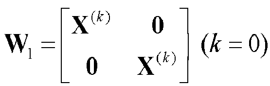


- To make the W2 overhead consistent for different W1 matrices, i2 = 8, ..., 15 shall be reserved for W2 corresponding to W1 matrices that are enhancement components (e.g. block diagonal).
- Alternatively, when


- The rank-3 PMI overhead for this example is shown in Table 4.
TABLE 4 W1 overhead (wideband) W2 overhead (subband) Rank-3 0-bit (w/o augmentation) 4-bit 1-bit (w/ augmentation) - It is possible that the Release 12 4Tx codebook does not comprise of the
Release 8 codebook. In that case, the identity matrix is removed from the W1 codebook C1. - Note that in any of the (Y1, Y2) pairs above, the two selection vectors inside the brackets can be permuted. For example, (


- It is not precluded that the Release 12 4Tx rank-3 codebook is redesigned using the GoB component as proposed above, and not include any
Release 8 4Tx rank-3 precoding matrices. - Another alternative GoB design is (N,Nb) = (8,8), where


- The simplest solution is to reuse
Release 8 codebook as-is for Release 12.
- → Size-1 (Rel-8 codebook only).
W 2 ∈ C 2,R8Tx4r4, where C 2,R8Tx4r4 denotes theRelease 8 4Tx rank-4 codebook used for W2. - If enhancement based on (N,Nb) structure is warranted by sufficient performance gain, it can be done in a similar fashion as for rank-1 and rank-2. For instance, based on a (N,Nb) = (4,4) design,

- → Size-2 (Rel-8 codebook augmented with block diagonal GoB)
- When W 1 = I 4, then W 2 ∈ C 2,R8Tx4r4, where C 2,R8Tx4r4 denotes the
Release 8 4Tx rank-4 codebook used for W2. - When


- Note there are a total of 8 W2 matricess (i2 = 0, ..., 7) for

- Alternatively, one may adopt a (N, Nb) = (8,8) codebook as below:

- → Size-2 (Rel-8 codebook augmented with block diagonal GoB).
- When W 1 = I 4, then W 2 ∈ C 2,R8Tx4r4, where C 2,R8Tx4r4 denotes the
Release 8 4Tx rank-4 codebook used for W2. - When



- Note that in any of the (Y 1, Y 2) pair above, the two selection vectors inside the brackets [ ] can be permuted.
- Also note that any (Y 1, Y 2) pair above can be replaced by a different pair denoted as (

- The rank-4 PMI overhead for this example is shown in Table 5.
TABLE 5 W1 overhead (wideband) W2 overhead (sub-band) Rank-4 0-bit (w/o augmentation) 4-bit 1-bit (w/ augmentation) - It is possible that the Release 12 4Tx codebook does not comprise of the
Release 8 codebook. In that case, the identity matrix is removed from the W1 codebook C1. - It is not precluded that the Release 12 4Tx rank-4 codebook is redesigned using the GoB component as proposed above, and not includes any
Release 8 4Tx rank-4 precoding matrices. - The final 4Tx codebook comprises of rank-r codebook, r = 1, 2, 3, 4. For each rank r, the corresponding rank-r codebook can be constructed by methods discussed above regarding rank-1 to rank-4 codebooks. It is not precluded that codebook is enhanced for certain rank(s), while for the other ranks,
Release 8 codebook is reused. - Using (N, Nb) = (16,4) as an example, the proposed codebook in the sections above may be re-formulated by the equations shown in the tables below. It should be noted that these tables can be easily extended to other (N, Nb) values.
- If Release 12 4Tx codebook for rank-1 and rank-2 is redesigned by the GoB framework with adjacent beams overlapping, and does not include the
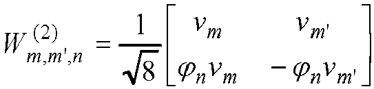
Release 8 codebook, the 4Tx codebooks can be expressed by equations in Tables 6-1 and 6-2. - A first PMI value of n 1 ∈ { 0,1,···, f(υ)-1} and a second PMI value of n 2 ∈ {0,1,···, g(υ)-1} correspond to the codebook indices n 1 and n 2 given in Table.6-j, where υ is equal to the associated rank value and where j = υ, f(υ) = {8,8} and g(υ) = {16,16}. Interchangeably, the first and second precoding matrix indicators are expressed by i 1 and i 2.
- The quantities ϕn and vm are expressed by


- Table 6-1 illustrates a codebook for 1-layer CSI reporting according to one embodiment.
TABLE 6-1 i 1 i 2 0 1 2 3 4 5 6 7 0-7 


i 1 i 2 8 9 10 11 12 13 14 15 0-7 


where 
- Table 6-2 illustrates a codebook for 2-layer CSI reporting according to one embodiment.
TABLE 6-2 i 1 i 2 0 1 2 3 0-7 


i 1 i 2 4 5 6 7 0 - 7 


i 1 i 2 8 9 10 11 0 - 7 


i 1 i 2 12 13 14 15 0 - 7 


- If the Release 12 4Tx codebook for rank-1 and rank-2 is designed by augmenting the existing
Release 8 codebook with GoB components, then the Release 12 4Tx codebook can be expressed as in Table 6-3 and Table 6-4. - Table 6-3 illustrates a codebook for 1-layer CSI reporting according to one embodiment.
TABLE 6-3 i 1 i 2 0 0 1 2 3 4 5 6 7 8 9 10 11 12 13 14 15 Use precoding matrix of index i 2 of Release 8 4Tx rank-1 codebooki 1 i 2 1-8 0 1 2 3 4 5 6 7 8 9 10 11 12 13 14 15 Corresponding to i 1 = 0-7 in table 6-1 - Table 6-4 illustrates a codebook for 2-layer CSI reporting according to one embodiment.
TABLE 6-4 i 1 i 2 0 0 1 2 3 4 5 6 7 8 9 10 11 12 13 14 15 Use precoding matrix of index i 2 of Release 8 4Tx rank-1 codebooki 1 i 2 1-8 0 1 2 3 4 5 6 7 8 9 10 11 12 13 14 15 Corresponding to i 1 = 0-7 in table 6-2 - If the Release 12 4Tx codebook for rank-3 and rank-3 is redesigned by the GoB framework with adjacent beams overlapping, and not includes the
Release 8 codebook, the 4Tx codebooks can be expressed by equations in Table 6-5 and 6-6. - Table 6-5 illustrates a codebook for 3-layer CSI reporting according to one embodiment.
TABLE 6-5 i 1 i 2 0 1 2 3 0 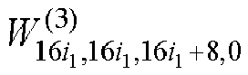
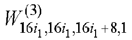


i 1 i 2 4 5 6 7 0 


i 1 i 2 8 9 10 11 0 


i 1 i 2 12 13 14 15 0 


where 
- Table 6-6 illustrates a codebook for 4-layer CSI reporting according to one embodiment.
TABLE 6-6 i 1 i 2 0 1 2 3 0 


i 1 i 2 4 5 6 7 0 


where 
- If the Release 12 4Tx codebook for rank-3 and rank-3 is designed by augmenting the existing
Release 8 codebook with GoB components, the Release 12 4Tx codebook can be expressed as in Table 6-7and Table 6-8. - Table 6-7 illustrates a codebook for 3-layer CSI reporting according to one embodiment.
TABLE 6-7 i 1 i 2 0 0 1 2 3 4 5 6 7 8 9 10 11 12 13 14 15 Use precoding matrix of index i 2 of Release 8 4Tx rank-3 codebooki 1 i 2 1-8 0 1 2 3 4 5 6 7 8 9 10 11 12 13 14 15 Corresponding to i 1 = 0-7 in Table 6-5. - Table 6-8 illustrates a codebook for 4-layer CSI reporting according to one embodiment.
TABLE 6-8 i 1 i 2 0 0 1 2 3 4 5 6 7 8 9 10 11 12 13 14 15 Use precoding matrix of index i 2 of Release 8 4Tx rank-4 codebooki 1 i 2 1-8 0 1 2 3 4 5 6 7 8 9 10 11 12 13 14 15 For i 2 = 0 - 7: corresponding to i 1 = 0-7 in Table 6-6. For i 2 = 8 - 15: reserved. - For the W1 codebook C1 proposed above, the GoB component is expressed in the form of a block diagonal matrix as



- Alternative designs are possible where the block diagonal sub-matrix of W1 (i.e. X(k)) is replaced by linear or non-linear transformations of X(k), for example:

- In the following section several such possible designs are described assuming (N,Nb) = (16,4) as an example, but extension to other (N, Nb) values are straightforward.
- It is also assumed that the Release 12 4Tx codebook is redesigned using the GoB structure and does not include the
Release 8 4Tx codebook; however it is straightforward to augment theRelease 8 4Tx codebook by the designs proposed below. - In one embodiment,


b k)modN b (Nb k+1)modN ··· b (Nb k+Nb-1)modN , the second sub-matrix D(m)X (k) comprises a different grid of Nb beams as

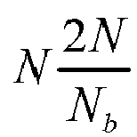
-
FIG. 4 illustrates an example in which a grid of beams is shifted by m = 2 beams. A first grid of Nb beams 401 is selected from N beams 402. The second grid ofbeams 403 is selected from the N beams 402, but is shifted by twobeams beams 401. - It is not precluded that a subset of D(m) matrices are used in constructing codebook C1, where m ∈ Π, Π ⊆ {0,....N - 1}. For instance, when Π ={1}, the Nb beams in the second grid of beams (e.g., for the vertical polarization array 402) are all shifted by 1 beam, which is half of the number of overlapping beams (Nb/2 = 2) between two consecutive W1 matrices. As another example, when Π = {0,1}, the second grid of Nb beams may be unshifted, or shifted by one beam.
- In another embodiment, both the first and second grid of beams may be shifted. This is expressed as:


- Similarly, it is possible to use a subset of G(n) and D(m) matrices in generating the codebook C1.
- It is further possible to permute the selected beams in one or both sub-matrices of W1. As one example, the W1 codebook is expressed as:

b .
One example of P(l) is
- Permutation can be performed for both sub-matrices of W1. In another example, the W1 codebook is expressed as

- In another embodiment,


- An alternative formulation of the phase rotation matrix D(m) is given as


- It will be further understood that combination of beam shifting, beam permutation, and/or phase rotation schemes can be used in constructing the W1 codebook.
- The LTE Release 10 8Tx codebook is designed using the GoB structure. Specifically:
- each 4Tx polarization array is over-sampled by N DFT beams'
- each wideband W1 matrix comprises Nb adjacent DFT beams to cover a certain AoD and angular spread, and
- narrowband W2 performs beam selection and co-phasing.
- To illustrate this pruning, the Release 10 8Tx codebook is denoted as


i ,:) denotes the ni-th row of H ,
- The 4Tx GoB codebooks proposed above may be pruned from the Release 10 8Tx codebook. The following notations are used herein:
-

-

-

-

- For a (N,Nb) = (N,Nb) 4Tx GoB codebook with overlapping beams, where N<= 32, Nb = 4, each 4Tx precoding matrix denoted by (
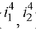


- More specifically:
For (N,Nb) = (8,4) 4Tx codebook with overlapping, each 4Tx precoding matrix denoted by a pair of 4Tx codebook indices (

TABLE 7 4Tx indices 

0-3 0 1 2 3 4 5 6 7 Corresponding 8Tx indices 

0 1 2 3 4 5 6 7 4Tx indices 

0-3 8 9 10 11 12 13 14 15 Corresponding 8Tx indices 

8 9 10 11 12 13 14 15 - For a (N,Nb) = (16,4) 4Tx codebook with overlapping beams, each 4Tx precoding matrix denoted by (


TABLE 8 4Tx indices 

0-7 0 1 2 3 4 5 6 7 Corresponding 8Tx indices 


0 1 2 3 4 5 6 7 4Tx indices 

0-7 8 9 10 11 12 13 14 15 Corresponding 8Tx indices 


8 9 10 11 12 13 14 15 - For (N,Nb) = (32,4) 4Tx codebook with overlapping beams, each 4Tx precoding matrix denoted by (


TABLE 9 4Tx indices 

0-15 0 1 2 3 4 5 6 7 Corresponding 8Tx indices 


0 1 2 3 4 5 6 7 4Tx indices 

0-15 8 9 10 11 12 13 14 15 Corresponding 8Tx indices 


8 9 10 11 12 13 14 15 - For a (N,Nb) = (N,Nb) 4Tx codebook without overlapping beams, where N<= 32, and Nb = 4, each 4Tx precoding matrix denoted by a pair of 4Tx codebook indices (

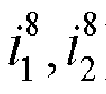

- More specifically:
For a (N,Nb) = (8,4) 4Tx codebook without overlapping beams, each 4Tx precoding matrix denoted by (

TABLE 10 4Tx indices 

0-1 0 1 2 3 4 5 6 7 Corresponding 8Tx indices 


0 1 2 3 4 5 6 7 4Tx indices 

0-1 8 9 10 11 12 13 14 15 Corresponding 8Tx indices 


8 9 10 11 12 13 14 15 - For a (N,Nb) = (16,4) 4Tx codebook without overlapping beams, each 4Tx precoding matrix denoted by (


TABLE 11 4Tx indices 

0-3 0 1 2 3 4 5 6 7 Corresponding 8Tx indices 


0 1 2 3 4 5 6 7 4Tx indices 

0-3 8 9 10 11 12 13 14 15 Corresponding 8Tx indices 


8 9 10 11 12 13 14 15 - For a (N,Nb) = (32,4) 4Tx codebook without overlapping beams, each 4Tx precoding matrix denoted by (


TABLE 12 4Tx indices 

0-7 0 1 2 3 4 5 6 7 Corresponding 8Tx indices 


0 1 2 3 4 5 6 7 4Tx indices 

0-7 8 9 10 11 12 13 14 15 Corresponding 8Tx indices 


8 9 10 11 12 13 14 15 - In this section, we assume the following 4Tx rank-2 codebook, where the W2 codebook is size-8.


- For a (N,Nb) = (N,Nb) 4Tx GoB codebook with overlapping beams, where N<= 32, Nb = 4, each 4Tx precoding matrix denoted by a pair of 4Tx codebook indices (


- More specifically:
For a (N,Nb) = (8,4) 4Tx codebook with overlapping beams, each 4Tx precoding matrix denoted by (

TABLE 13 4Tx indices 

0-3 0 1 2 3 4 5 6 7 Corresponding 8Tx indices 


0 1 2 3 4 5 6 7 - For a (N,Nb) = (16,4) 4Tx codebook with overlapping beams, each 4Tx precoding matrix denoted by (

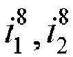
TABLE 4Tx indices 

0-7 0 1 2 3 4 5 6 7 Corresponding 8Tx indices 


0 1 2 3 4 5 6 7 - For a (N,Nb) = (32,4) 4Tx codebook with overlapping beams, each 4Tx precoding matrix denoted by (


TABLE 15 4Tx indices 

0-15 0 1 2 3 4 5 6 7 Corresponding 8Tx indices 


0 1 2 3 4 5 6 7 - For a (N,Nb) = (N,Nb) 4Tx codebook without overlapping beams, where N<= 32, Nb = 4, each 4Tx precoding matrix denoted by a pair of 4Tx codebook indices (


- For a (N,Nb) = (8,4) 4Tx codebook without overlapping beams, each 4Tx precoding matrix denoted by (


TABLE 16 4Tx indices 

0-1 0 1 2 3 4 5 6 7 Corresponding 8Tx indices 


0 1 2 3 4 5 6 7 - For a (N,Nb) = (16,4) 4Tx codebook without overlapping beams, each 4Tx precoding matrix denoted by (


TABLE 17 4Tx indices 

0-3 0 1 2 3 4 5 6 7 Corresponding 8Tx indices 


0 1 2 3 4 5 6 7 - For a (N,Nb) = (32,4) 4Tx codebook without overlapping beams, each 4Tx precoding matrix denoted by (


TABLE 18 4Tx indices 

0-7 0 1 2 3 4 5 6 7 Corresponding 8Tx indices 


0 1 2 3 4 5 6 7 - In this section, we assume the following 4Tx GoB codebook where the W2 codebook is size-16.



- Such a 4Tx codebook cannot be completely pruned out of the 8Tx codebook unless the oversampling rate is N = 32, which is equivalent to the 8Tx oversampling rate. In this case, when there is W1 overlapping for 4Tx, each 4Tx precoding matrix denoted by a pair of 4Tx codebook indices (

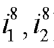


TABLE 19 4Tx indices 

0-15 0 1 2 3 4 5 6 7 Corresponding 8Tx indices 


0 1 2 3 4 5 6 7 4Tx indices 

0-15 8 9 10 11 12 13 14 15 Corresponding 8Tx indices 


8 9 10 11 12 13 14 15 - For a (N,Nb) = (32,4) 4Tx GoB codebook without overlapping beams, each 4Tx precoding matrix denoted by a pair of 4Tx codebook indices (


TABLE 20 

4Tx indices 0-7 0 1 2 3 4 5 6 7 Corresponding 8Tx indices 


0 1 2 3 4 5 6 7 4Tx indices 

0-7 8 9 10 11 12 13 14 15 Corresponding 8Tx indices 


8 9 10 11 12 13 14 15 - A rank-3 4Tx GoB codebook cannot be pruned from the rank-3 8Tx codebook. This can be seen from the 8Tx design, which followed the (N,Nb) = (16,8) structure, where





- The column vectors of each rank-3 8Tx precoding matrix comprise critically sampled (e.g. sampling rate 4) 4Tx DFT vectors in order to ensure that a rank-3 8Tx precoding matrix satisfies the unitary constraint. For 4Tx, in order to achieve the unitary constraint, column vectors of each rank-3 4Tx precoding matrix must comprise critically sampled (e.g. sampling rate 2) 2Tx DFT vectors. As such, the column vectors of any 4Tx GoB matrix will always span across different W1 matrices of the 8Tx codebook, leaving it impossible to construct the rank-3 4-Tx codebook by pruning the 8Tx codebook.
- However the rank-3 4Tx GoB component can be pruned from the rank-6 8Tx codebook, where


- For instance, for the (N,Nb) = (4,4) GoB codebook, the pruning shown in Table 21 is possible:
TABLE 21 4Tx indices 

0 arbitrary Corresponding 8Tx indices 

0 0 - Note that the column-selection method ( m1, m2, m3) may depend on the 4Tx GoB precoding matrix. For instance:


- Similarly, the rank-4 4Tx GoB component cannot be pruned from the rank-4 8Tx codebook. However, a rank-4 4Tx GoB component can be pruned from the rank-8 8Tx codebook, where


TABLE 22 4Tx indices 

0 arbitrary Corresponding 8Tx indices 

0 0 - Note that the column -selection method (m1, m2, m3, m4) may depend on the 4Tx GoB precoding matrix. For instance:



- In one embodiment, the row selection vector ( n1,n2,n3,n4) is hard-coded / fixed in the specification, and is not signalled to the UE.
FIG. 5 illustrates an example of using a row selection vector to prune antenna pairs in an 8Tx array. Eight antennas 1-8 are arranged in four cross-polarized pairs 501-504. Using the row selection vector ( n1,n2,n3,n4) = [1,2,5,6] prunes the first two cross-polarized antenna pairs 501, 502 from the8Tx array 505 for a4Tx deployment 506. - In another embodiment, the row selection vector (n1,n2,n3,n4) may be semi-statically radio resource control (RRC)-configd for a UE, and can be different for different UEs. There are multiple possible methods for RRC signalling (n1,n2,n3,n4)
- For the k-th antenna port of a 4-Tx MIMO system (k = 1, 2, 3, 4), the eNodeB signals the corresponding virtual antenna port index nk in an 8-Tx MIMO system. This requires a signaling overhead of log2(8) × 4 = 12 bits.
- As there are a total of

- It is further possible to down-size the set of candidate antenna selection vectors {(n1,n2,n3,n4)}, which may further reduce the RRC signalling overhead. For instance, the eNodeB may use 1-bit to config the UE to assume (n1,n2,n3,n4) = [1,2,5,6] or (n1,n2,n3,n4) = [1,4,5,8]. With (n1,n2,n3,n4) = [1,4,5,6], two adjacent cross-polarized antenna pairs are configd, which models 4Tx cross-polarized antennas with small antenna spacing. With (n1,n2,n3,n4) = [1,4,5,8], two antenna pairs with large antenna spacing are modelled. This may be important for some wireless operators that must deploy wide antenna spacing due to their GSM/HSPA/LTE spectrum farming limitation, where two separate antenna radomes with large spacing are used for 4Tx MIMO.
- For a UE configd in transmission mode 10, where the UE is configd with multiple CSI-RS resources, the row selection vector (n1,n2,n3,n4) can be independently configd for each 4-Tx CSI-RS resource.
- Using the methods proposed above for rank-1,2,3,4Tx GoB codebooks, one example of a 4Tx codebook is summarized below.
- Release 12 enhancement is achieved by augmenting the
Release 8 codebook with double-codebook (DCB) components. - component 1 (Release 8): W1 = identity matrix, W2 selected from
Release 8 codebook, - component 2 (DCB):...pruned Release 10 8Tx codebook,
-
- Component 1: Release 8


- Component 2: DCB:
- W1: i 1 = 0,...15, each W1 is the (1,2,5,6) th row of the (i 1) th 8Tx W1 codebook.
- W2: i 2 = 0,...15, same as 8Tx W2 codebook
-
- Component 1: Release 8


- Component 2: DCB:
- W1: i 1 = 0,...15, each W1 is the (1,2,5,6) th row of the (i 1) th 8Tx W1 codebook.
- W2: i 2 = 0,...15, same as 8Tx W2 codebook.
- Re-use the
Release 8 codebook. - Further enhancement of 4Tx codebook
- Any of the codebooks proposed above can be further enhanced by adding more 4Tx precoding matrices. Note that in the sections above, the
Release 8 4Tx codebook is inherited in Release 12 4Tx codebook in the form of W = W1W2, where W1 is a 4x4 identity matrix and W2 are taken fromRelease 8 codebook. An extension of this design is possible, where the W1 codebook not only includes the 4x4 identity matrix I4, but also includes other size 4x4 matrices. One example extension is where the W1 codebook comprises of a set of diagonal matrices, where each diagonal element performs phase rotation for each row of W2 matrix. - Following this design principle, an example of a further-enhanced 4Tx codebook is given below.
-

For i 1 = 0, ..., N /2- 1, W 1 (0),W 1 (1),W 1 (2) ... W 1 (N/2-1) are diagonal matrices (e.g. performing phase rotation), and W2 inherits theRelease 8 4Tx codebook. In particular, for i 1 = 0, W 1 (0) = I 4. This allows theRelease 8 codebook to be re-used without change in Release 12. - When i 1 = (N/2), ..., N-1, then W 1 (N/2) ... W 1 (N-1) are block diagonal matrices designed with double-codebook structure. In this case, W1 and W2 can use any of the DCB codebook components proposed in the sections above. As one example, W1/W2 may be pruned 8Tx codebooks, where N = 32, and W1: i 1 = 16,...31, each W1 is the (1,2,5,6)th row of the (i 1 -15) th 8Tx W1 matrix, W2: i 2 = 0,...15, same as 8Tx W2 codebook.
- Herein, the W1 overhead is 5-bit, and W2 overhead is 4-bits per subband.
- Rank-3 and rank-4 may follow the same enhancement design if necessary.
- The GoB designs proposed above assumed that each W1 matrix comprises a group of adjacent DFT beams. It is noted that the beams in each W1 grid are not necessarily adjacent, which makes other designs possible. In this section we propose an example rank-2 design with non-adjacent beams in W1.
- To recapture the notations, note that

- It is noted that an N-times oversampled 2×1 DFT beam expressed as

b (l+N/2)mod N .
Therefore each W1 grid may comprise two orthogonal DFT beams expressed as

- The W2 codebook may comprise beam selection and co-phasing matrixes, for example, denoted as:


- As an example,

1 ,i2 , i 2 = 0,...15 are expressed as shown in Table 23.TABLE 23 i 2 =0,...,3 


i 2 =4,...,7 


i 2 = 8,...,11 


i 2 =12,...,15 


- It is noted that W i
1 ,i2 , i 2 = 4,...,7 are identical to W i1 ,i2 , i 2 = 0,...,3, and W i1 ,i2 , i 2 = 12,...,15 are identical to W i1 ,i2, i 2 = 8,...,11. Therefore it's possible to reduce the W2 size to 3-bits (i 2 = 0,...,7), where
1 ,i2 is given by the values shown in Table 24.TABLE 24 i 2 =0,...,3 


i 2 = 4,...,7 
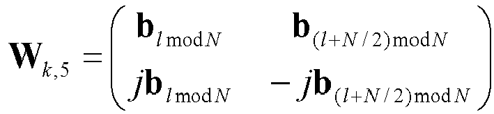


- Note that other co-phasing methods Ω are possible, for example

- In this case, the W2 codebook size is 4-bits.
- The precoders proposed above as
alternative design 1 may be combined with the precoders in the previous sections to construct the final rank-2 codebook. For example, assuming over-sampling ratio N (e.g. N = 16), Nb = 4, the rank-2 codebook may be expressed as
- -> size N12
- When i 2 = 0,...,7:


- When i 2 = 8,...,15:



- The W1 overhead is log2(N/2) = 3-bits, and the W2 overhead is 4-bits.
- Note that the combined codebook can be re-expressed below.

- → size N
- When



- When



- In this case, the W1 overhead is log2(N) = 4-bits, and the W2 overhead is 3-bits.
- Another possible combinatorial design is

- → size N
- When


- When


- The W1 overhead is log2(N) = 4-bits, and the W2 overhead is 4-bits.
- As proposed in the previous sections, it is possible for the Release 12 codebook to inherit the
Release 8 codebook as a subset. This can be achieved by using theRelease 8 4Tx precoder as the codebook for W2 which is associated with W1 = 4×4 identity matrix I4. This is applicable for rank-1 to rank-4, where the subband W2 overhead is 4-bits per subband. - It is also possible to divide the
Release 8 precoders into N groups, where each group has 16/N Release 8 precoders that form a different W2 codebook. For each W2 codebook, the W1 matrix is equivalent to a 4×4 identity matrix. The subband W2 overhead will therefore be reduced to log2(16/N) bits. - For example:
- The
Release 8 codebook is inherited in Release 12 codebook, corresponding to two W1 matrices, e.g.,

Release 8 precoders. For
Release 8 precoders. - Other values of N are possible to adapt the subband PMI bit-width. For example, N = 2 corresponds to a subband size of log2(8) = 3-bits, N = 4 corresponds to a subband size of log2(4) = 2 bits.
- The above designs can be applied for rank-1, rank-2, rank-3, and rank-4.
- It is further possible to inherit the
Release 8 codebook in Release 12 by constructing the W1 matrix withRelease 8 precoders, and constructing the W2 codebook with column selection matrices. - For example:
- For rank-1, W1 includes all or a subset of
Release 8 rank-1 vectors. The size of W1 is given by 4×L, where 1<=L<=16 is the number of rank-1Release 8 codebook vectors that are included in W1. The W2 codebook comprises L column-selection vectors [e 1 , e 2 ... e L], where ei is an L×1 vector of all zero entries, except for the i-th entry, which is equivalent to 1. - For rank-r (r= 2, 3, 4), the columns of W1 comprise all or a subset of
Release 8 rank-r vectors, e.g. this may be denoted as

th Release 8 precoder. The size of W1 is 4×rL, where 1<=L<=16 is the number of rank-r Release 8 codebook matrices in W1. The W2 codebook comprises L column-selection matrices, where the l-th W2 matrix (1<= l <= L) is
- Alternatively, the W1 matrix can be constructed in a block diagonal manner.
- For example, for rank-1:

sizes 2×16, where the l-th column of A is the first two rows of the l-th Release 8 precoder, and the l-th column of B is the last two rows of the l-th Release 8 precoder, l = 1, ..., 16. - The W2 matrix can be written in the form of

- For rank-r, r = 2, ..., 4:

sizes 2 × 16r , and where -

-

- For the W2 codebook,


- In the following section, possible 4Tx codebook enhancement alternatives for LTE Release 12 are disclosed. In these examples, ẽ i is a 4×1 vector with all zero entries except for the i-th element which has
value 1. - For a rank-1/2 codebook, the following two alternatives are possible.
- Reusing the 8Tx GoB design with N = 32 over-sampled beams and 4 adjacent beams per grid, the following 4Tx codebook can be considered.




-


-


- For rank-2, if a (3-bit) W2 is preferred, (Y1, Y2) can be changed to:

- A rank-1/2 codebook comprises two components, where W1 structures are different in each component. For the first 8 W1 matrices, Xn comprise four adjacent DFT beams with over-sampling rate of N = 16. For the last 8 W1 matrices, Xn comprise four distributed non-adjacent DFT beams uniformly sampling the [0, 360] angle of arrival sub-space. This provides wider angular spread coverage and may be beneficial to large timing misalignment error.
- The W1 codebook therefore can be given by:
- i 1=0,1,···,7:


- i 1 = 8,9,···,15:


- As can be seen, for the last eight W1 matrices, each W1 matrix in codebook C1 is comprised of four non-adjacent DFT beams. The four DFT beams in each W1 matrix are widely spaced and uniformly distributed in the [0,360] DFT subspace to cover a wide range of angle-of-arrivals/departures. The DFT beams in a first W1 matrix are rotated by a small angle against four DFT beams in a second W1 matrix. More specifically, the W1 matrices comprising widely spaced DFT beams are summarized as

- Such a design framework is particularly beneficial in uses cases (e.g., widely spaced antenna components, un-calibrated antenna array, rich multipath scattering environment) where the angle-of-arrival/departures of the incoming wireless signals are distributed in a wide range. For instance, in a heterogeneous deployment scenario where dense small cells are overlaid on top of macro base station on the same frequency, the multipath radio signals received by a UE are reflected by numerous scattering objects surrounding the UE (e.g., building, cars). Have widely spaced and non-adjacent DFT beams in W1 ensures that all incoming signals from different angles can be properly captured. As another use case, it is noted that the transmitter timing at different antennas on a base station shall be synchronized by careful timing alignment calibration. In practice, perfect timing alignment cannot always be guaranteed at a base station, especially for low-cost low-power small base stations (e.g. pico-cells, femto-cells) with cheaper RF components. In 3GPP LTE, a maximum 65 nano-second downlink transmission timing misalignment requirement is set forth for all base stations. A consequence of misaligned antenna timing in the time domain is the increased channel variation on different OFDM subcarriers in the frequency domain, and the main DFT beam angle on one frequency subband can be significantly different than the main DFT beam angle on another subband. In this case, having non-adjacent widely spaced DFT beams in the W1 matrix ensures that the wideband angle-of-arrival/departures can be more reliably covered, resulting in higher feedback accuracy.
- The W2 codebook for rank-1 (4-bit) may be given by:


- The W2 codebook for rank-2 (4-bit) may be given by:
For W2 corresponding to i 1 = 0,1, ···,7

- If a (3-bit) W2 is preferred, (Y1, Y2) may be changed to:

- For W2 corresponding to i 1 = 8,9, ···,15


- If a (3-bit) W2 is preferred, the W2 codebook may be changed to




- In one embodiment, the new rank-1/2 codebook designs set forth above may be incorporated into an LTE system complying with LTE Release 12. A subset of precoders in the proposed codebooks above may be used to construct a new Release 12 4Tx codebook, for either rank-1 or rank-2. For example, the W1 codebook may be constructed by W1 matrices only comprising widely spaced DFT beams, e.g., i2 = 8, 9, ... 15 in Equation (110) - (111).
-
FIG. 6 illustrates the precoding matrix/vector selection process according to one embodiment. The final precoding matrix/vector is a function of two PMIs:
-
FIG. 6 illustrates the technique used in downlink LTE-Advanced (LTE-A). The UE selects PMIi and PMI2 and hence W1 and W2 in a manner similar to the LTE feedback paradigm. - The UE first selects the first precoder codebook W1 in
block 601 based on the long-term channel properties such as spatial covariance matrix such as in a spatial correlation domain from an input of PMIi. This is done in a long-term basis consistent with the fact that spatial covariance matrix needs to be estimated over a long period of time and in a wideband manner. - Conditioned upon W1, the UE selects W2 based on the short-term (instantaneous) channel. This is a two stage process. In
block 602, a set of codebooks CB2 (0) to CB2 (N-1) is selected based upon the PMIi input.Block 603 selects one precoder corresponding to the selected codebook CB2 (PMI 1 ) and PMI2. This selection may be conditioned upon the selected rank indicator (RI). Alternatively, RI can be selected jointly with W2. Block 604 takes the selected W1 and W2 and forms the function f(W 1, W 2). - PMIi and PMI2 are reported to the base station (eNodeB) at different rates and/or different frequency resolutions.
- Based on this design framework, several types of codebook design are described herein. While each type can stand alone, it is also possible to use different types in a single codebook design especially if the design is intended for different scenarios. A simple yet versatile design can be devised as follows:
- PMIi selects one of the N codebooks W1 as indicated above.
- PMI2 selects at least one of the column vectors of W, wherein the number of selected column vectors is essentially the recommended transmission rank (RI).
- This design allows construction of N different scenarios where the codebook W1 for each scenario is chosen to contain a set of basis vectors for a particular spatial channel characteristic W2. While any two-dimensional function can be used in equation (124), this disclosure assumes a product (matrix multiplication) function f(x,y)=xy. Thus the final short-term precoding matrix/vector is computed as a matrix product of W1 and W2: W = W 1 W 2 .
-
FIG. 7 is a block diagram illustrating internal details of amobile UE 701 and aneNodeB 702 in the network system ofFIG. 1 . Mobile UE 701 may represent any of a variety of devices such as a server, a desktop computer, a laptop computer, a cellular phone, a Personal Digital Assistant (PDA), a smart phone or other electronic devices. In some embodiments, the electronic mobile UE 701 communicates with eNodeB 702 based on a LTE or Evolved Universal Terrestrial Radio Access Network (E-UTRAN) protocol. Alternatively, another communication protocol now known or later developed can be used. - Mobile UE 701 comprises a
processor 703 coupled to amemory 704 and atransceiver 705. Thememory 704 stores (software) applications 706 for execution by theprocessor 703. The applications could comprise any known or future application useful for individuals or organizations. These applications could be categorized as operating systems (OS), device drivers, databases, multimedia tools, presentation tools, Internet browsers, emailers, Voice-Over-Internet Protocol (VOIP) tools, file browsers, firewalls, instant messaging, finance tools, games, word processors or other categories. Regardless of the exact nature of the applications, at least some of the applications may direct themobile UE 701 to transmit UL signals to eNodeB (base-station) 702 periodically or continuously via thetransceiver 705. In at least some embodiments, the mobile UE 701 identifies a Quality of Service (QoS) requirement when requesting an uplink resource from eNodeB 702. In some cases, the QoS requirement may be implicitly derived by eNodeB 702 from the type of traffic supported by themobile UE 701. As an example, VOIP and gaming applications often involve low-latency uplink (UL) transmissions while High Throughput (HTP)/Hypertext Transmission Protocol (HTTP) traffic can involve high-latency uplink transmissions. - Transceiver 705 includes uplink logic which may be implemented by execution of instructions that control the operation of the transceiver. Some of these instructions may be stored in
memory 704 and executed when needed byprocessor 703. As would be understood by one of skill in the art, the components of the uplink logic may involve the physical (PHY) layer and/or the Media Access Control (MAC) layer of thetransceiver 705. Transceiver 705 includes one ormore receivers 707 and one ormore transmitters 708. -
Processor 703 may send or receive data to various input/output devices 709. A subscriber identity module (SIM) card stores and retrieves information used for making calls via the cellular system. A Bluetooth baseband unit may be provided for wireless connection to a microphone and headset for sending and receiving voice data.Processor 703 may send information to a display unit for interaction with a user ofmobile UE 701 during a call process. The display may also display pictures received from the network, from a local camera, or from other sources such as a Universal Serial Bus (USB) connector.Processor 703 may also send a video stream to the display that is received from various sources such as the cellular network viaRF transceiver 705 or the camera. - During transmission and reception of voice data or other application data,
transmitter 707 may be or become non-synchronized with its serving eNodeB. In this case, it sends a random access signal. As part of this procedure, it determines a preferred size for the next data transmission, referred to as a message, by using a power threshold value provided by the serving eNodeB, as described in more detail above. In this embodiment, the message preferred size determination is embodied by executing instructions stored inmemory 704 byprocessor 703. In other embodiments, the message size determination may be embodied by a separate processor/memory unit, by a hardwired state machine, or by other types of control logic, for example. - eNodeB 702 comprises a
processor 710 coupled to amemory 711,symbol processing circuitry 712, and atransceiver 713 viabackplane bus 714. The memory stores applications 715 for execution byprocessor 710. The applications could comprise any known or future application useful for managing wireless communications. At least some of theapplications 715 may direct eNodeB 702 to manage transmissions to or from mobile UE 701. -
Transceiver 713 comprises an uplink Resource Manager, which enables eNodeB 702 to selectively allocate uplink Physical Uplink Shared CHannel (PUSCH) resources to mobile UE 701. As would be understood by one of skill in the art, the components of the uplink resource manager may involve the physical (PHY) layer and/or the Media Access Control (MAC) layer of thetransceiver 713. Transceiver 713 includes at least onereceiver 715 for receiving transmissions from various UEs within range of eNodeB 702 and at least one transmitter 716for transmitting data and control information to the various UEs within range ofeNodeB 702. - The uplink resource manager executes instructions that control the operation of
transceiver 713. Some of these instructions may be located inmemory 711 and executed when needed onprocessor 710. The resource manager controls the transmission resources allocated to each UE 701 served by eNodeB 702 and broadcasts control information via the PDCCH. -
Symbol processing circuitry 712 performs demodulation using known techniques. Random access signals are demodulated insymbol processing circuitry 712. - During transmission and reception of voice data or other application data,
receiver 715 may receive a random access signal from a UE 701. The random access signal is encoded to request a message size that is preferred by UE 701. UE 701 determines the preferred message size by using a message threshold provided by eNodeB 702. In this embodiment, the message threshold calculation is embodied by executing instructions stored inmemory 711 byprocessor 710. In other embodiments, the threshold calculation may be embodied by a separate processor/memory unit, by a hardwired state machine, or by other types of control logic, for example. Alternatively, in some networks the message threshold is a fixed value that may be stored inmemory 711, for example. In response to receiving the message size request, eNodeB 702 schedules an appropriate set of resources and notifies UE 701 with a resource grant. - Those skilled in the art will appreciate that modifications may be made to the described embodiments, and also that many other embodiments are possible, within the scope of the claimed invention.


Claims (18)
- A method, comprising:selecting, by a user equipment (UE), a precoding matrix W for channel state information (CSI) feedback, the precoding matrix W being equal to a product of two matrices W1 and W2, wherein the W1 matrix is selected from a codebook that includes matrices W 1 (k) for k = 0, ..., N - 1, and wherein each W 1 (k) matrix can be written in the following form:
 where 0 is a matrix with all entries being equal to zero,where X (k) is a matrix having one column equal to b l mod N and another column equal to b (l+N/2)mod N , where k=l, andwhere:
 where N is an integer greater than one;determining, by the UE, first and second precoding matrix indicator (PMI) indices that correspond to the selected precoding matrix W, the first PMI index corresponding to the W1 matrix, the second PMI index corresponding to the W2 matrix; andtransmitting, by the UE, data indicative of the first and second PMI indices.
 - The method of claim 1, wherein the codebook is a first codebook, and wherein the W2 matrix is selected from a second codebook that includes the following matrices:


- The method of claim 2, wherein the second codebook includes the following matrices:


- The method of claim 1, wherein the codebook is a first codebook, and wherein the W2 matrix is selected from a second codebook that includes the following matrices:


- The method of claim 1, wherein the codebook is a first codebook, and wherein the W2 matrix is selected from a second codebook that includes the following matrices:


- The method of any one of claims 2, 4, or 5, wherein:

- The method of any of one of claims 1-6, wherein the precoding matrix W is derived from a matrix multiplication of two matrices W1 and W2.
- The method of any of one of claims 1-7,configuring the UE to operate in a physical uplink shared channel (PUSCH) mode; andtransmitting the data indicative of the first and second PMI indices according to the PUSCH mode.
- The method of claim 8, wherein the PUSCH mode is PUSCH mode 3-2.
- A user equipment (UE), comprising:one or more processors configured to:
select a precoding matrix W for channel state information (CSI) feedback, the precoding matrix W being equal to a product of two matrices W1 and W2, wherein the W1 matrix is selected from a codebook that includes matrices W 1 (k) for k = 0, ..., N - 1, and wherein each W 1 (k) matrix can be written in the following form: where 0 is a matrix with all entries being equal to zero,where X (k) is a matrix having one column equal to b l mod N and another column equal to b (l+N/2)mod N , where k=l, andwhere:
 where N is an integer greater than one; and
determine first and second precoding matrix indicator (PMI) indices that correspond to the selected precoding matrix W, the first PMI index corresponding to the W 1 matrix, the second PMI index corresponding to the W 2 matrix; anda transmitter configured to transmit data indicative of the first and second PMI indices. - The UE of claim 10, wherein the codebook is a first codebook, and wherein the W 2 matrix is selected from a second codebook that includes the following matrices:


- The UE of claim 11, wherein the second codebook includes the following matrices:


- The UE of claim 10, wherein the codebook is a first codebook, and wherein the W 2 matrix is selected from a second codebook that includes the following matrices:


- The UE of claim 10, wherein the codebook is a first codebook, and wherein the W 2 matrix is selected from a second codebook that includes the following matrices:


- The UE of any of claims 11, 13 and 14, wherein:

- The UE of any one of claims 10-15, wherein the precoding matrix W is derived from a matrix multiplication of two matrices W 1 and W 2.
- The UE of any one of claims 10-16,wherein the one or more processors are configured to configure the UE to operate in a physical uplink shared channel (PUSCH) mode, andwherein the transmitter is configured to transmit the data indicative of the first and second PMI indices according to the PUSCH mode.
- The UE of claim 17, wherein the PUSCH mode is PUSCH mode 3-2.
Applications Claiming Priority (11)
| Application Number | Priority Date | Filing Date | Title |
|---|---|---|---|
| US201361763804P | 2013-02-12 | 2013-02-12 | |
| US201361768851P | 2013-02-25 | 2013-02-25 | |
| US201361769463P | 2013-02-26 | 2013-02-26 | |
| US201361770705P | 2013-02-28 | 2013-02-28 | |
| US201361777664P | 2013-03-12 | 2013-03-12 | |
| US201361807647P | 2013-04-02 | 2013-04-02 | |
| US201361812459P | 2013-04-16 | 2013-04-16 | |
| US201361817657P | 2013-04-30 | 2013-04-30 | |
| US14/177,547 US9281881B2 (en) | 2013-02-12 | 2014-02-11 | 4TX codebook enhancement in LTE |
| EP14751985.4A EP2992705B1 (en) | 2013-02-12 | 2014-02-12 | 4tx codebook enhancement in lte |
| PCT/US2014/016011 WO2014126992A2 (en) | 2013-02-12 | 2014-02-12 | 4tx codebook enhancement in lte |
Related Parent Applications (1)
| Application Number | Title | Priority Date | Filing Date |
|---|---|---|---|
| EP14751985.4A Division EP2992705B1 (en) | 2013-02-12 | 2014-02-12 | 4tx codebook enhancement in lte |
Publications (2)
| Publication Number | Publication Date |
|---|---|
| EP4478626A2 true EP4478626A2 (en) | 2024-12-18 |
| EP4478626A3 EP4478626A3 (en) | 2025-03-26 |
Family
ID=51297411
Family Applications (2)
| Application Number | Title | Priority Date | Filing Date |
|---|---|---|---|
| EP24183974.5A Pending EP4478626A3 (en) | 2013-02-12 | 2014-02-12 | 4tx codebook enhancement in lte |
| EP14751985.4A Active EP2992705B1 (en) | 2013-02-12 | 2014-02-12 | 4tx codebook enhancement in lte |
Family Applications After (1)
| Application Number | Title | Priority Date | Filing Date |
|---|---|---|---|
| EP14751985.4A Active EP2992705B1 (en) | 2013-02-12 | 2014-02-12 | 4tx codebook enhancement in lte |
Country Status (5)
| Country | Link |
|---|---|
| US (10) | US9281881B2 (en) |
| EP (2) | EP4478626A3 (en) |
| JP (4) | JP6539586B2 (en) |
| CN (4) | CN104982060B (en) |
| WO (1) | WO2014126992A2 (en) |
Families Citing this family (70)
| Publication number | Priority date | Publication date | Assignee | Title |
|---|---|---|---|---|
| US12596402B2 (en) | 2012-03-14 | 2026-04-07 | Popsockets Llc | Docking connector platform for mobile electronic devices |
| US9804636B2 (en) | 2012-03-14 | 2017-10-31 | David B. Barnett | Docking connector platform for mobile electronic devices |
| CN106603136B (en) | 2012-06-14 | 2022-08-19 | 华为技术有限公司 | Method for determining precoding matrix indication, user equipment and base station evolution node |
| CN103944621B (en) * | 2013-01-18 | 2017-12-05 | 上海贝尔股份有限公司 | It is determined that the method for the two-stage codebook set suitable for the configuration of 4Tx cross polarised antennas |
| US9281881B2 (en) * | 2013-02-12 | 2016-03-08 | Texas Instruments Incorporated | 4TX codebook enhancement in LTE |
| CN104969497A (en) * | 2013-03-08 | 2015-10-07 | 富士通株式会社 | Method for determining codebook, information feedback method and device thereof |
| CN108809388B (en) | 2013-04-03 | 2022-03-08 | 华为技术有限公司 | Channel state information reporting method, receiving method and device |
| US10027388B2 (en) * | 2013-04-26 | 2018-07-17 | Intel IP Corporation | Wireless transmission precoding |
| CN112039566B (en) | 2013-05-10 | 2022-07-29 | 华为技术有限公司 | Method for determining precoding matrix indication, user equipment and base station |
| CN108494450B (en) | 2013-08-08 | 2020-06-16 | 华为技术有限公司 | Method for determining precoding matrix indication, receiving equipment and transmitting equipment |
| WO2015167316A1 (en) * | 2014-05-02 | 2015-11-05 | 엘지전자 주식회사 | Improved beamforming method in multi-antenna wireless communication system and apparatus for same |
| WO2015180178A1 (en) * | 2014-05-30 | 2015-12-03 | 华为技术有限公司 | Method and device for reporting channel status information (csi), and base station antenna |
| US9825742B2 (en) | 2014-10-03 | 2017-11-21 | Samsung Electronics Co., Ltd. | Codebook design and structure for advanced wireless communication systems |
| CN106716896B (en) * | 2014-10-10 | 2020-01-24 | 华为技术有限公司 | Device, method and system for acquiring precoding information |
| WO2016068628A1 (en) * | 2014-10-31 | 2016-05-06 | Samsung Electronics Co., Ltd. | Codebook design and structure for advanced wireless communication systems |
| US9654195B2 (en) * | 2014-11-17 | 2017-05-16 | Samsung Electronics Co., Ltd. | Methods to calculate linear combination pre-coders for MIMO wireless communication systems |
| US9893777B2 (en) | 2014-11-17 | 2018-02-13 | Samsung Electronics Co., Ltd. | Method and apparatus for precoding channel state information reference signal |
| WO2016175623A1 (en) * | 2015-04-29 | 2016-11-03 | Samsung Electronics Co., Ltd. | Apparatus and method for using codebook wireless communication system |
| US9806781B2 (en) | 2015-04-29 | 2017-10-31 | Samsung Electronics Co., Ltd. | Codebook design and structure for advanced wireless communication systems |
| WO2016206052A1 (en) * | 2015-06-25 | 2016-12-29 | Intel IP Corporation | User equipment and codebook search method for 4tx dual codebook (ran1) |
| EP3327944A4 (en) * | 2015-07-23 | 2019-03-20 | LG Electronics Inc. | METHOD FOR TRANSMITTING AND RECEIVING A SIGNAL BASED ON A CODEBOOK IN A MULTI-ANTENNA WIRELESS COMMUNICATION SYSTEM AND APPARATUS THEREFOR |
| US10039104B2 (en) | 2015-08-14 | 2018-07-31 | Industrial Technology Research Institute | Dynamic beamforming method and related apparatuses using the same |
| CN107925454B (en) * | 2015-08-24 | 2022-02-25 | 华为技术有限公司 | A method and device for sending and feeding back precoding information |
| WO2017039511A1 (en) | 2015-09-04 | 2017-03-09 | Telefonaktiebolaget Lm Ericsson (Publ) | Precoding a transmission from an antenna array that includes co-polarized antenna elements aligned in a given spatial dimension |
| CN107148761B (en) * | 2015-09-30 | 2020-02-14 | 华为技术有限公司 | Communication method and device based on codebook feedback |
| US10439690B2 (en) * | 2015-10-23 | 2019-10-08 | Samsung Electronics Co., Ltd. | Precoder codebook for advanced wireless communication systems |
| CN108352870B (en) | 2015-11-04 | 2021-07-27 | 瑞典爱立信有限公司 | Method and transmitting radio node for precoding transmission from an antenna array |
| US10763925B2 (en) * | 2015-11-11 | 2020-09-01 | Samsung Electronics Co., Ltd. | Method and apparatus for reduced feedback MIMO |
| CN106803768A (en) * | 2015-11-25 | 2017-06-06 | 北京信威通信技术股份有限公司 | A kind of method for generating the long-term code book of precoding |
| CN106803767A (en) * | 2015-11-25 | 2017-06-06 | 北京信威通信技术股份有限公司 | The generation method and system of the long-term code book of precoding |
| CN106803766A (en) * | 2015-11-25 | 2017-06-06 | 北京信威通信技术股份有限公司 | A kind of system for generating the long-term code book of precoding |
| US10498407B2 (en) | 2015-12-30 | 2019-12-03 | Lg Electronics Inc. | Method for transmitting and receiving codebook based signal in multi-antenna wireless communication system and apparatus therefor |
| CN107181513B (en) * | 2016-03-11 | 2021-01-22 | 电信科学技术研究院 | Method and device for feedback of channel state information |
| CN107181509A (en) | 2016-03-11 | 2017-09-19 | 电信科学技术研究院 | A kind of data transmission method and device |
| US10056956B2 (en) * | 2016-03-24 | 2018-08-21 | Samsung Electronics Co., Ltd. | Precoder codebook for CSI reporting in advanced wireless communication systems |
| WO2017171485A1 (en) * | 2016-03-31 | 2017-10-05 | 엘지전자 주식회사 | Method for transmitting feedback information for dm-rs-based downlink transmission in wireless communication system and apparatus therefor |
| WO2017166219A1 (en) * | 2016-03-31 | 2017-10-05 | Qualcomm Incorporated | Channel covariance feedback for enhanced fd-mimo |
| CN109951220B (en) * | 2016-04-01 | 2020-03-10 | 华为技术有限公司 | A kind of feedback method and device of precoding matrix indication |
| CN107370530B (en) * | 2016-05-12 | 2021-02-12 | 华为技术有限公司 | Channel state information feedback method, precoding method, terminal equipment and base station |
| CN107863999B (en) * | 2016-09-22 | 2021-01-22 | 电信科学技术研究院 | Signal transmission method and device |
| CN108023621B (en) * | 2016-11-04 | 2022-07-15 | 中兴通讯股份有限公司 | A method, device and electronic device for channel information quantization feedback |
| CN108282207B (en) * | 2017-01-06 | 2021-06-15 | 华为技术有限公司 | A kind of precoding matrix indication method, apparatus and system |
| WO2018129733A1 (en) * | 2017-01-16 | 2018-07-19 | 华为技术有限公司 | Method for determining channel state information, access network device, and terminal device |
| CN108390704B (en) * | 2017-02-03 | 2021-06-25 | 上海诺基亚贝尔股份有限公司 | Method and apparatus for MIMO communication |
| CN115664476B (en) | 2017-02-06 | 2024-09-27 | 中兴通讯股份有限公司 | A channel information feedback and receiving method and device |
| CN108988917B (en) * | 2017-04-26 | 2019-07-12 | 华为技术有限公司 | Method, equipment and the computer storage medium of a kind of instruction and determining precoding vector |
| CN108966246B (en) * | 2017-05-24 | 2021-08-27 | 上海华为技术有限公司 | Signal processing method and base station |
| CN109150267B (en) * | 2017-06-16 | 2023-12-08 | 华为技术有限公司 | A method and device for sending and receiving channel state information |
| US10601485B2 (en) * | 2017-09-07 | 2020-03-24 | Lg Electronics Inc. | Method for transmitting a uplink signal based on a codebook in a wireless communication system and apparatus therefor |
| WO2019057094A1 (en) * | 2017-09-19 | 2019-03-28 | Mediatek Inc. | Codebook-based uplink transmission in wireless communications |
| US10594374B2 (en) * | 2017-09-19 | 2020-03-17 | Mediatek Inc. | Codebook-based uplink transmission in wireless communications |
| TW201924245A (en) * | 2017-10-02 | 2019-06-16 | 聯發科技股份有限公司 | A method for constructing and using a codebook and an apparatus thereof |
| US10707939B2 (en) * | 2017-10-03 | 2020-07-07 | Mediatek Inc. | Codebook-based uplink transmission in wireless communications |
| EP3711175A1 (en) * | 2017-11-17 | 2020-09-23 | Telefonaktiebolaget LM Ericsson (Publ) | Acknowledgement signaling for radio access networks |
| US12363212B2 (en) | 2018-01-08 | 2025-07-15 | Popsocket Llc | Magnetic wallet accessory |
| US10735059B2 (en) * | 2018-02-13 | 2020-08-04 | Qualcomm Incorporated | Dynamic beamforming using a co-phasing factor |
| US11539465B2 (en) * | 2018-02-16 | 2022-12-27 | Telefonaktiebolaget Lm Ericsson (Publ) | HARQ codebook structure |
| CN113660018A (en) * | 2018-05-11 | 2021-11-16 | 华为技术有限公司 | Channel estimation method and device |
| CN110752866B (en) * | 2018-07-23 | 2021-08-20 | 华为技术有限公司 | Massive multiple-input multiple-output MIMO precoding transmission method and device |
| CN108847876B (en) * | 2018-07-26 | 2021-03-02 | 东南大学 | Large-scale MIMO time-varying channel state information compression feedback and reconstruction method |
| US11902025B2 (en) * | 2018-09-28 | 2024-02-13 | Telefonaktiebolaget Lm Ericsson (Publ) | HARQ codebook structure |
| WO2020135101A1 (en) * | 2018-12-29 | 2020-07-02 | 华为技术有限公司 | Vector indication method for constructing precoding vector, and communications device |
| CN113302427A (en) | 2019-01-18 | 2021-08-24 | 鲍勃斯科特有限责任公司 | Grip for foldable electronic device |
| US12224828B2 (en) | 2019-02-14 | 2025-02-11 | Apple Inc. | Method of type II CSI reporting for multiple spatial layers |
| CN113992250B (en) * | 2019-02-15 | 2023-01-06 | Oppo广东移动通信有限公司 | Codebook information processing method, terminal equipment and network equipment |
| KR102589080B1 (en) | 2019-04-04 | 2023-10-16 | 노키아 테크놀로지스 오와이 | Uplink control information |
| WO2022128062A1 (en) * | 2020-12-14 | 2022-06-23 | Telefonaktiebolaget Lm Ericsson (Publ) | Transform for communication symbols |
| US12068832B2 (en) * | 2021-11-30 | 2024-08-20 | Qualcomm Incorporated | Beam selection and codebook learning based on XR perception |
| CN116436499A (en) * | 2021-12-30 | 2023-07-14 | 中国移动通信有限公司研究院 | An information processing method, device, device and readable storage medium |
| US20260100733A1 (en) * | 2024-10-04 | 2026-04-09 | Interdigital Patent Holdings, Inc. | Methods, architectures, apparatuses and systems for precoder reporting |
Family Cites Families (33)
| Publication number | Priority date | Publication date | Assignee | Title |
|---|---|---|---|---|
| JP2000278193A (en) * | 1999-03-23 | 2000-10-06 | Toshiba Corp | Diversity antenna device |
| EP2003787B1 (en) * | 2006-03-31 | 2013-11-20 | National Institute of Information and Communications Technology | Wireless network system |
| TWI470957B (en) * | 2006-10-30 | 2015-01-21 | Interdigital Tech Corp | Method and apparatus for processing feedback in a wireless communication system |
| CN101330479B (en) * | 2007-06-20 | 2011-04-20 | 中兴通讯股份有限公司 | Method for pre-encoding multi-input multi-output transmission and codebook encoding |
| CN101394256B (en) * | 2007-09-19 | 2012-07-04 | 中兴通讯股份有限公司 | Pre-coding method and codebook constructing method based on codebook mode |
| US8811353B2 (en) * | 2008-04-22 | 2014-08-19 | Texas Instruments Incorporated | Rank and PMI in download control signaling for uplink single-user MIMO (UL SU-MIMO) |
| JP5105370B2 (en) * | 2008-12-12 | 2012-12-26 | 独立行政法人情報通信研究機構 | COMMUNICATION SYSTEM, TERMINAL DEVICE, COMMUNICATION METHOD, AND PROGRAM |
| US20120270535A1 (en) * | 2009-12-17 | 2012-10-25 | Texas Instruments Incorporated | Implicit CSI Feedback for DL Multiuser MIMO Transmission |
| JP5258002B2 (en) * | 2010-02-10 | 2013-08-07 | マーベル ワールド トレード リミテッド | Device, mobile communication terminal, chipset, and method in MIMO communication system |
| CN102158263B (en) * | 2010-02-11 | 2015-12-02 | 索尼公司 | Codebook-based channel information feedback method, device and system |
| ATE557503T1 (en) * | 2010-02-17 | 2012-05-15 | Research In Motion Ltd | SYSTEM AND METHOD FOR CHANNEL STATUS INFORMATION FEEDBACK IN A WIRELESS COMMUNICATIONS SYSTEM USING MULTIPLE INPUT AND OUTPUT TRANSMISSION |
| JP5281604B2 (en) * | 2010-03-09 | 2013-09-04 | 株式会社エヌ・ティ・ティ・ドコモ | Codebook control method, base station apparatus and mobile station apparatus |
| KR20110109992A (en) * | 2010-03-29 | 2011-10-06 | 엘지전자 주식회사 | Efficient Feedback Method and Apparatus in Multi-antenna Supported Wireless Communication System |
| US8848817B2 (en) | 2010-04-30 | 2014-09-30 | Texas Instruments Incorporated | Transmission modes and signaling for uplink MIMO support or single TB dual-layer transmission in LTE uplink |
| CN101826951B (en) * | 2010-05-05 | 2016-03-30 | 中兴通讯股份有限公司 | The method of feeding back channel state information and device |
| CN102237984B (en) * | 2010-05-07 | 2014-02-12 | 电信科学技术研究院 | A method and device for reporting CSI based on PUSCH |
| US8842772B2 (en) * | 2010-06-17 | 2014-09-23 | Panasonic Intellectual Property Corporation Of America | Pre-coding method and transmitter |
| CN101860420B (en) * | 2010-06-18 | 2015-08-12 | 中兴通讯股份有限公司 | A kind of channel information acquisition method and system |
| CN101877627B (en) * | 2010-06-21 | 2015-09-16 | 中兴通讯股份有限公司 | The feedback method of channel condition information and terminal |
| CN102299774B (en) * | 2010-06-24 | 2013-09-18 | 上海贝尔股份有限公司 | Method for determining pre-coded matrix and corresponding communication method and equipment |
| KR101806878B1 (en) * | 2010-08-16 | 2018-01-10 | 삼성전자주식회사 | Codebook for 8 transmission antennas and multiple input multiple output communication system of the codebook |
| US8693421B2 (en) * | 2010-09-02 | 2014-04-08 | Texas Instruments Incorporated | Downlink 8 TX codebook sub-sampling for CSI feedback |
| CN102404084B (en) * | 2010-09-16 | 2014-06-18 | 上海贝尔股份有限公司 | Method for determining pre-coding matrix and corresponding communication method and equipment |
| CN101958773B (en) * | 2010-09-30 | 2016-08-24 | 中兴通讯股份有限公司 | The method of feedback channel information and terminal |
| CN102447501B (en) | 2010-10-07 | 2015-04-29 | 上海贝尔股份有限公司 | Codebook sub-sampling method applied to LTE-A system and device thereof |
| WO2012063980A1 (en) * | 2010-11-08 | 2012-05-18 | Pantech Co.,Ltd. | Terminal and base station, method thereof in wireless communication system |
| WO2012093742A1 (en) * | 2011-01-04 | 2012-07-12 | Pantech Co.,Ltd. | Terminal and base station, method thereof in wireless communication system |
| CN102122983B (en) * | 2011-04-18 | 2014-08-06 | 电信科学技术研究院 | Codebook generation method, information sending method, information feedback method and equipment |
| US8781018B2 (en) * | 2011-04-25 | 2014-07-15 | Texas Instruments Incorporated | Six transmit antenna codebook design |
| CN102868479B (en) * | 2011-07-07 | 2015-06-03 | 华为技术有限公司 | Method, device and system for multi-antenna transmission |
| US8913682B2 (en) * | 2012-05-18 | 2014-12-16 | Samsung Electronics Co., Ltd. | Apparatus and method for channel state information codeword construction for a cellular wireless communication system |
| CN102916768B (en) * | 2012-09-19 | 2016-06-29 | 华为技术有限公司 | The feedback method of High-Speed Dedicated Physical Control Channel, device and system |
| US9281881B2 (en) * | 2013-02-12 | 2016-03-08 | Texas Instruments Incorporated | 4TX codebook enhancement in LTE |
-
2014
- 2014-02-11 US US14/177,547 patent/US9281881B2/en active Active
- 2014-02-12 EP EP24183974.5A patent/EP4478626A3/en active Pending
- 2014-02-12 CN CN201480008443.3A patent/CN104982060B/en active Active
- 2014-02-12 CN CN201610414091.2A patent/CN105939170B/en active Active
- 2014-02-12 CN CN202010452849.8A patent/CN111628808B/en active Active
- 2014-02-12 CN CN202010458753.2A patent/CN111654317B/en active Active
- 2014-02-12 JP JP2015557217A patent/JP6539586B2/en active Active
- 2014-02-12 WO PCT/US2014/016011 patent/WO2014126992A2/en not_active Ceased
- 2014-02-12 EP EP14751985.4A patent/EP2992705B1/en active Active
-
2015
- 2015-09-23 US US14/863,156 patent/US9319121B2/en active Active
-
2016
- 2016-02-26 US US15/055,195 patent/US9425871B2/en active Active
- 2016-04-18 US US15/132,024 patent/US9780850B2/en active Active
-
2017
- 2017-09-07 US US15/698,015 patent/US10361760B2/en active Active
-
2019
- 2019-06-10 JP JP2019107680A patent/JP6741382B2/en active Active
- 2019-07-22 US US16/518,597 patent/US10742280B2/en active Active
-
2020
- 2020-07-22 JP JP2020125829A patent/JP7121408B2/en active Active
- 2020-08-10 US US16/989,587 patent/US11095346B2/en active Active
-
2021
- 2021-08-16 US US17/403,587 patent/US11563470B2/en active Active
-
2022
- 2022-07-29 JP JP2022121298A patent/JP7486550B2/en active Active
-
2023
- 2023-01-23 US US18/100,466 patent/US12126411B2/en active Active
-
2024
- 2024-10-21 US US18/921,300 patent/US20250055515A1/en active Pending
Also Published As
Similar Documents
| Publication | Publication Date | Title |
|---|---|---|
| US12126411B2 (en) | 4Tx codebook enhancement in LTE | |
| JP7663309B2 (en) | Codebook subsampling for CSI feedback on PUCCH for 4Tx MIMO - Patent application | |
| US12470264B2 (en) | Transmission modes and signaling for uplink MIMO support or single TB dual-layer transmission in LTE uplink | |
| US9369193B2 (en) | Efficient feedback transmission method in multi-antenna wireless communication system and device for same |
Legal Events
| Date | Code | Title | Description |
|---|---|---|---|
| PUAI | Public reference made under article 153(3) epc to a published international application that has entered the european phase |
Free format text: ORIGINAL CODE: 0009012 |
|
| STAA | Information on the status of an ep patent application or granted ep patent |
Free format text: STATUS: THE APPLICATION HAS BEEN PUBLISHED |
|
| AC | Divisional application: reference to earlier application |
Ref document number: 2992705 Country of ref document: EP Kind code of ref document: P |
|
| AK | Designated contracting states |
Kind code of ref document: A2 Designated state(s): AL AT BE BG CH CY CZ DE DK EE ES FI FR GB GR HR HU IE IS IT LI LT LU LV MC MK MT NL NO PL PT RO RS SE SI SK SM TR |
|
| REG | Reference to a national code |
Ref country code: DE Ref legal event code: R079 Free format text: PREVIOUS MAIN CLASS: H04B0007060000 Ipc: H04W0024080000 |
|
| PUAL | Search report despatched |
Free format text: ORIGINAL CODE: 0009013 |
|
| AK | Designated contracting states |
Kind code of ref document: A3 Designated state(s): AL AT BE BG CH CY CZ DE DK EE ES FI FR GB GR HR HU IE IS IT LI LT LU LV MC MK MT NL NO PL PT RO RS SE SI SK SM TR |
|
| RIC1 | Information provided on ipc code assigned before grant |
Ipc: H04B 7/06 20060101ALI20250217BHEP Ipc: H04B 7/04 20170101ALI20250217BHEP Ipc: H04W 24/08 20090101AFI20250217BHEP |
|
| STAA | Information on the status of an ep patent application or granted ep patent |
Free format text: STATUS: REQUEST FOR EXAMINATION WAS MADE |
|
| 17P | Request for examination filed |
Effective date: 20250926 |
|
| STAA | Information on the status of an ep patent application or granted ep patent |
Free format text: STATUS: EXAMINATION IS IN PROGRESS |
|
| 17Q | First examination report despatched |
Effective date: 20260324 |