EP4478586A2 - Motor and binding machine - Google Patents
Motor and binding machine Download PDFInfo
- Publication number
- EP4478586A2 EP4478586A2 EP24181962.2A EP24181962A EP4478586A2 EP 4478586 A2 EP4478586 A2 EP 4478586A2 EP 24181962 A EP24181962 A EP 24181962A EP 4478586 A2 EP4478586 A2 EP 4478586A2
- Authority
- EP
- European Patent Office
- Prior art keywords
- rotor core
- rotor
- magnet
- rotation shaft
- motor
- Prior art date
- Legal status (The legal status is an assumption and is not a legal conclusion. Google has not performed a legal analysis and makes no representation as to the accuracy of the status listed.)
- Pending
Links
Images



Classifications
-
- H—ELECTRICITY
- H02—GENERATION; CONVERSION OR DISTRIBUTION OF ELECTRIC POWER
- H02K—DYNAMO-ELECTRIC MACHINES
- H02K1/00—Details of the magnetic circuit
- H02K1/06—Details of the magnetic circuit characterised by the shape, form or construction
- H02K1/22—Rotating parts of the magnetic circuit
- H02K1/27—Rotor cores with permanent magnets
- H02K1/2706—Inner rotors
- H02K1/272—Inner rotors the magnetisation axis of the magnets being perpendicular to the rotor axis
- H02K1/274—Inner rotors the magnetisation axis of the magnets being perpendicular to the rotor axis the rotor consisting of two or more circumferentially positioned magnets
- H02K1/2753—Inner rotors the magnetisation axis of the magnets being perpendicular to the rotor axis the rotor consisting of two or more circumferentially positioned magnets the rotor consisting of magnets or groups of magnets arranged with alternating polarity
-
- B—PERFORMING OPERATIONS; TRANSPORTING
- B21—MECHANICAL METAL-WORKING WITHOUT ESSENTIALLY REMOVING MATERIAL; PUNCHING METAL
- B21F—WORKING OR PROCESSING OF METAL WIRE
- B21F15/00—Connecting wire to wire or other metallic material or objects; Connecting parts by means of wire
- B21F15/02—Connecting wire to wire or other metallic material or objects; Connecting parts by means of wire wire with wire
- B21F15/04—Connecting wire to wire or other metallic material or objects; Connecting parts by means of wire wire with wire without additional connecting elements or material, e.g. by twisting
-
- H—ELECTRICITY
- H02—GENERATION; CONVERSION OR DISTRIBUTION OF ELECTRIC POWER
- H02K—DYNAMO-ELECTRIC MACHINES
- H02K1/00—Details of the magnetic circuit
- H02K1/06—Details of the magnetic circuit characterised by the shape, form or construction
- H02K1/22—Rotating parts of the magnetic circuit
- H02K1/28—Means for mounting or fastening rotating magnetic parts on to, or to, the rotor structures
-
- H—ELECTRICITY
- H02—GENERATION; CONVERSION OR DISTRIBUTION OF ELECTRIC POWER
- H02K—DYNAMO-ELECTRIC MACHINES
- H02K1/00—Details of the magnetic circuit
- H02K1/06—Details of the magnetic circuit characterised by the shape, form or construction
- H02K1/22—Rotating parts of the magnetic circuit
- H02K1/27—Rotor cores with permanent magnets
- H02K1/2706—Inner rotors
- H02K1/272—Inner rotors the magnetisation axis of the magnets being perpendicular to the rotor axis
- H02K1/274—Inner rotors the magnetisation axis of the magnets being perpendicular to the rotor axis the rotor consisting of two or more circumferentially positioned magnets
- H02K1/2753—Inner rotors the magnetisation axis of the magnets being perpendicular to the rotor axis the rotor consisting of two or more circumferentially positioned magnets the rotor consisting of magnets or groups of magnets arranged with alternating polarity
- H02K1/278—Surface mounted magnets; Inset magnets
-
- B—PERFORMING OPERATIONS; TRANSPORTING
- B25—HAND TOOLS; PORTABLE POWER-DRIVEN TOOLS; MANIPULATORS
- B25F—COMBINATION OR MULTI-PURPOSE TOOLS NOT OTHERWISE PROVIDED FOR; DETAILS OR COMPONENTS OF PORTABLE POWER-DRIVEN TOOLS NOT PARTICULARLY RELATED TO THE OPERATIONS PERFORMED AND NOT OTHERWISE PROVIDED FOR
- B25F5/00—Details or components of portable power-driven tools not particularly related to the operations performed and not otherwise provided for
-
- B—PERFORMING OPERATIONS; TRANSPORTING
- B65—CONVEYING; PACKING; STORING; HANDLING THIN OR FILAMENTARY MATERIAL
- B65B—MACHINES, APPARATUS OR DEVICES FOR, OR METHODS OF, PACKAGING ARTICLES OR MATERIALS; UNPACKING
- B65B13/00—Bundling articles
- B65B13/02—Applying and securing binding material around articles or groups of articles, e.g. using strings, wires, strips, bands or tapes
- B65B13/025—Hand-held tools
-
- B—PERFORMING OPERATIONS; TRANSPORTING
- B65—CONVEYING; PACKING; STORING; HANDLING THIN OR FILAMENTARY MATERIAL
- B65B—MACHINES, APPARATUS OR DEVICES FOR, OR METHODS OF, PACKAGING ARTICLES OR MATERIALS; UNPACKING
- B65B13/00—Bundling articles
- B65B13/18—Details of, or auxiliary devices used in, bundling machines or bundling tools
- B65B13/24—Securing ends of binding material
- B65B13/28—Securing ends of binding material by twisting
-
- B—PERFORMING OPERATIONS; TRANSPORTING
- B65—CONVEYING; PACKING; STORING; HANDLING THIN OR FILAMENTARY MATERIAL
- B65B—MACHINES, APPARATUS OR DEVICES FOR, OR METHODS OF, PACKAGING ARTICLES OR MATERIALS; UNPACKING
- B65B13/00—Bundling articles
- B65B13/18—Details of, or auxiliary devices used in, bundling machines or bundling tools
- B65B13/24—Securing ends of binding material
- B65B13/28—Securing ends of binding material by twisting
- B65B13/285—Hand tools
-
- E—FIXED CONSTRUCTIONS
- E04—BUILDING
- E04G—SCAFFOLDING; FORMS; SHUTTERING; BUILDING IMPLEMENTS OR AIDS, OR THEIR USE; HANDLING BUILDING MATERIALS ON THE SITE; REPAIRING, BREAKING-UP OR OTHER WORK ON EXISTING BUILDINGS
- E04G21/00—Preparing, conveying, or working-up building materials or building elements in situ; Other devices or measures for constructional work
- E04G21/12—Mounting of reinforcing inserts; Prestressing
- E04G21/122—Machines for joining reinforcing bars
- E04G21/123—Wire twisting tools
-
- H—ELECTRICITY
- H02—GENERATION; CONVERSION OR DISTRIBUTION OF ELECTRIC POWER
- H02K—DYNAMO-ELECTRIC MACHINES
- H02K11/00—Structural association of dynamo-electric machines with electric components or with devices for shielding, monitoring or protection
- H02K11/20—Structural association of dynamo-electric machines with electric components or with devices for shielding, monitoring or protection for measuring, monitoring, testing, protecting or switching
- H02K11/21—Devices for sensing speed or position, or actuated thereby
- H02K11/215—Magnetic effect devices, e.g. Hall-effect or magneto-resistive elements
-
- H—ELECTRICITY
- H02—GENERATION; CONVERSION OR DISTRIBUTION OF ELECTRIC POWER
- H02K—DYNAMO-ELECTRIC MACHINES
- H02K7/00—Arrangements for handling mechanical energy structurally associated with dynamo-electric machines, e.g. structural association with mechanical driving motors or auxiliary dynamo-electric machines
- H02K7/14—Structural association with mechanical loads, e.g. with hand-held machine tools or fans
- H02K7/145—Hand-held machine tool
Definitions
- the present disclosure relates to a motor and a binding machine that is driven by a motor and binds an object to be bound such as a reinforcing bar with a wire.
- Reinforcing bars are used in concrete structures to improve strength, and are bound with wires to be prevented from shifting from prescribed positions during concrete pouring.
- a binding machine referred to as a reinforcing bar binding machine that winds a wire around two or more reinforcing bars and twists the wire wound around the reinforcing bars to bind the two or more reinforcing bars with the wire (for example, see JP6791141B ).
- a motor used in twisting the wire is required to repeat forward and reverse rotation at high speed and perform angle control with high accuracy.
- SPM surface permanent magnet
- the magnet since the magnet is attached to the outer periphery of the rotor core, the magnet may be peeled off the rotor core by a centrifugal force applied to the magnet when the rotor rotates.
- the present disclosure provides a SPM motor that can prevent peeling of a magnet, and a binding machine including the motor.
- a motor includes: a rotor; and a stator.
- the rotor includes: a rotation shaft; a rotor core; a magnet attached to an outer periphery of the rotor core, the magnet including a protrusion protruding along a direction in which the rotation shaft extends from an end surface of the rotor core; and a sealing member disposed between the protrusion and the rotation shaft.
- a motor includes: a rotor; and a stator.
- the rotor includes: a rotation shaft; a rotor core; a plurality of magnets attached to an outer periphery of the rotor core, the magnets including a plurality of protrusions protruding along a direction in which the rotation shaft extends from an end surface of the rotor core; and a sealing member disposed between the plurality of protrusions.
- a binding machine includes: a wire feeder configured to feed a wire; a curl forming unit configured to form an annular feeding path for winding the wire fed by the wire feeder around an object to be bound; a binding unit configured to twist the wire wound around the object to be bound; and a motor configured to drive the binding unit.
- the motor includes: a rotor; and a stator.
- the rotor includes: a rotation shaft; a rotor core; a magnet attached to an outer periphery of the rotor core, the magnet including a protrusion protruding along a direction in which the rotation shaft extends from an end surface of the rotor core; and a sealing member disposed between the protrusion and the rotation shaft.
- a binding machine includes: a wire feeder configured to feed a wire; a curl forming unit configured to form an annular feeding path for winding the wire fed by the wire feeder around an object to be bound; a binding unit configured to twist the wire wound around the object to be bound; and a motor configured to drive the binding unit.
- the motor includes: a rotor; and a stator.
- the rotor includes: a rotation shaft; a rotor core; a plurality of magnets attached to an outer periphery of the rotor core, the magnets including a plurality of protrusions protruding along a direction in which the rotation shaft extends from an end surface of the rotor core; and a sealing member disposed between the plurality of protrusions.
- the sealing member is filled between the protrusion of the magnet and the rotation shaft which protrude from the end surface of the rotor core. Further, the sealing member is filled between the protrusions of the magnets which is adjacent along the circumferential direction of the rotor core and protrude from the end surface of the rotor core.
- the sealing member bonds the rotation shaft and the protrusion of the magnet.
- the sealing member bonds the adjacent protrusion along the circumferential direction of the rotor core. Accordingly, even when the rotor rotates, an unbalanced load in which the magnet is rolled to an outer side by an own inertial force is prevented, and the magnet can be prevented from being peeled off the rotor core.
- FIG. 1 is an internal configuration view seen from a side that illustrates an example of an overall configuration of the reinforcing bar binding machine according to the present embodiment.
- a reinforcing bar binding machine 1A is used by an operator holding it in a hand and includes a body 10 and a handle 11.
- the reinforcing bar binding machine 1A feeds a wire W in a forward direction indicated by an arrow F, winds the wire W around reinforcing bars S that are objects to be bound, feeds the wire W wound around the reinforcing bars S in a reverse direction indicated by an arrow R, winds the wire W around the reinforcing bars S, and then twists the wire W to bind the reinforcing bars S with the wire W.
- the reinforcing bar binding machine 1A binds the reinforcing bars S with a plurality of wires W, and in this example, two wires W.
- the reinforcing bar binding machine 1A includes a magazine 2 in which the wires W are accommodated, a wire feeder 3 that feeds the two wires W side by side in a radial direction of the wires W, and a wire guide 4 that guides the two wires W fed to the wire feeder 3.
- the reinforcing bar binding machine 1A further includes a curl forming unit 5 that forms an annular feeding path for winding the two wires W fed by the wire feeder 3 around the reinforcing bars S, and a cutter 6 that cuts the two wires W wound around the reinforcing bars S.
- the reinforcing bar binding machine 1A further includes a binding unit 7 that twists the two wires W wound around the reinforcing bars S, and a drive unit 8 that drives the binding unit 7.
- the magazine 2 houses a reel 20 in a rotatable and detachable manner, on which the elongated wires W are wound to be fed out.
- the wires W include wires formed of plastically deformable metal wires, wires having metal wires covered with resins, or stranded wires. The two wires W are wound around the reel 20, and can be pulled out from the reel 20 at the same time.
- the wire feeder 3 includes a pair of feeding gears 30 that sandwich and feed the two wires W side by side.
- rotation of a feeding motor (not illustrated) is transmitted to one of the pair of feeding gears 30.
- rotation of one feeding gear 30 is transmitted to the other feeding gear 30 by gear meshing.
- the wire feeder 3 arranges the two wires W side by side along a direction in which the pair of feeding gears 30 are arranged side by side.
- rotation directions of the feeding gears 30 are switched by switching forward and reverse rotation directions of the feeding motor (not illustrated), and forward and reverse feeding directions of the wires W are switched.
- the wire guide 4 is disposed upstream and downstream (not illustrated) of the feeding gears 30 in the forward feeding direction of the wires W.
- the wire guide 4 arranges the two entered wires W along the direction in which the pair of feeding gears 30 are arranged side by side, and guides the wires W to between the pair of feeding gears 30.
- the curl forming unit 5 includes a curl guide 50 that curls the two wires W fed by the wire feeder 3 and regulates an orientation in which the two wires Ware arranged side by side, and an introducing guide 51 that introduces the two wires W curled by the curl guide 50 to the binding unit 7.
- the curl forming unit 5 curls the two wires W fed by the wire feeder 3 and passing through the curl guide 50, so that an annular feeding path Ru from the curl guide 50 to the binding unit 7 through the introducing guide 51 as illustrated by two-dot chain lines in FIG. 1 is formed.
- the cutter 6 includes a fixed blade 60, a movable blade 61 that cuts the wires W in cooperation with the fixed blade 60, and a transmission mechanism 62 that transmits an operation of the binding unit 7 to the movable blade 61.
- the cutter 6 cuts the wires W by rotation of the movable blade 61 with the fixed blade 60 as a fulcrum shaft.
- the binding unit 7 includes a wire locking body 70 to which the wires W are locked, and a sleeve 71 that actuates the wire locking body 70.
- the drive unit 8 includes a motor 80 and a speed reducer 81 that performs speed reduction and torque amplification.
- the reinforcing bar binding machine 1A includes, at an end of a feeding path of the wires W passing through the annular feeding path Ru and locked by the wire locking body 70, a feeding regulator 90 against which distal ends of the wires W abut.
- the curl guide 50 and the introducing guide 51 of the curl forming unit 5 are provided at a front end of the body 10.
- the reinforcing bar binding machine 1A is further provided with, between the curl guide 50 and the introducing guide 51 at the front end of the body 10, an abutting portion 91 against which the reinforcing bars S abut.
- the handle 11 extends downward from the body 10.
- a battery 15 is detachably attached to a lower portion of the handle 11.
- the magazine 2 is provided in front of the handle 11.
- the wire feeder 3, the cutter 6, the binding unit 7, the drive unit 8 that drives the binding unit 7, and the like are housed in the body 10.
- a trigger 12 is provided on a front side of the handle 11, and a switch 13 is provided inside the handle 11.
- the reinforcing bar binding machine 1A controls the feeding motor (not illustrated) and the motor 80 by a controller in accordance with a state of the switch 13 pressed by an operation of the trigger 12.
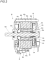
- FIG. 2 is a side sectional view illustrating an example of the motor according to the present embodiment.
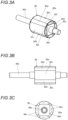
- FIG. 3A is a perspective view illustrating the example of the rotor according to the present embodiment
- FIG. 3B is a side view illustrating the example of the rotor according to the present embodiment
- FIG. 3C is a back view illustrating the example of the rotor according to the present embodiment.
- FIG. 4A is a side sectional view illustrating the example of the rotor according to the present embodiment
- FIG. 4B is a back sectional view illustrating the example of the rotor according to the present embodiment.
- FIG. 5A is an exploded perspective view illustrating the example of the rotor according to the present embodiment
- FIG. 5B is a perspective view of the example of the rotor according to the present embodiment before being filled with a sealing member.
- the motor 80 includes a rotor 82, a stator 83, a sensor 84, and a case 85.
- the motor 80 has a surface permanent magnet (SPM) structure.
- the rotor 82 includes a rotation shaft 82a, a rotor core 82b, a magnet 82c, a sealing member 82d, and a covering member 82e.
- the rotation shaft 82a is rotatably supported by a bearing 85a provided in the case 85.
- the rotor core 82b is made of metal and has a predetermined shape.
- the rotation shaft 82a is attached to a center of the rotor core 82b.
- the rotor core 82b is provided with a mounting portion 82f for the magnet 82c on an outer periphery.
- the mounting portion 82f has an uneven shape to which the magnet 82c is fitted.
- the magnet 82c is a permanent magnet and is attached to the outer periphery of the rotor core 82b.
- the magnet 82c has a shape for being fitted to the mounting portion 82f of the rotor core 82b, and is attached to the mounting portion 82f with an adhesive 82g.
- the adhesive 82g is, for example, an epoxy resin.
- magnets 82c are mounted at equal intervals along a circumferential direction of the rotor core 82b of the rotor 82.
- a gap 82h is defined between the adjacent magnets 82c along the circumferential direction of the rotor core 82b.
- the magnet 82c includes a protrusion 82i.
- the protrusion 82i protrudes along a direction in which the rotation shaft 82a extends from one end surface 82j of the rotor core 82b. Accordingly, a gap 82k is defined among the protrusion 82i, the rotation shaft 82a, and the one end surface 82j of the rotor core 82b.
- a gap 82h2 is defined between the adjacent protrusions 82i along the circumferential direction of the rotor core 82b.
- the sealing member 82d is a resin that has an adhesive property to members such as the rotation shaft 82a, the rotor core 82b, and the magnet 82c, and is filled in the gap 82k.
- the sealing member 82d is, for example, an epoxy resin.
- the sealing member 82d is filled in the gap 82k and solidified to be bonded to the rotation shaft 82a and the protrusion 82i of the magnet 82c.
- the sealing member 82d is filled in the gap 82k and solidified to be bonded to the rotation shaft 82a, the end surface 82j of the rotor core 82b, and the protrusion 82i of the magnet 82c. Accordingly, at least the rotation shaft 82a and the protrusion 82i of the magnet 82c bonded by the sealing member 82d.
- the rotation shaft 82a, the end surface 82j of the rotor core 82b, and the protrusion 82i of the magnet 82c may be bonded by the sealing member 82d.
- the sealing member 82d is filled in the gap 82h.
- the sealing member 82d is filled in the gap 82h and solidified to be bonded to the rotor core 82b and the magnet 82c. Accordingly, the adjacent magnets 82c along the circumferential direction of the rotor core 82b are bonded by the sealing member 82d.
- the sealing member 82d is filled in the gap 82h2 between the adjacent protrusions 82i along the circumferential direction of the rotor core 82b.
- the sealing member 82d is filled in the gap 82h2 and solidified to be bonded to the protrusion 82i of the magnet 82c. Accordingly, the adjacent protrusions 82i along the circumferential direction of the rotor core 82b are bonded by the sealing member 82d.
- a surface of the magnet 82c is painted to improve an adhesive property between the adhesive 82g and the sealing member 82d and prevent rust.
- An epoxy resin for example, is painted to the surface of the magnet 82c.
- the paint applied to the surface of the magnet 82c may have affinity to the adhesive 82g and the sealing member 82d.
- the covering member 82e covers an outer periphery of the magnet 82c attached to the mounting portion 82f of the rotor core 82b.
- the covering member 82e is formed of a resin tube having thermal contraction properties.
- the covering member 82e covers the outer periphery of the magnet 82c in a state of applying a force to an inner side in a radial direction of the rotor core 82b by thermal contraction.
- the sealing member 82d is filled in the gaps 82k and 82h after the outer periphery of the magnet 82c is covered with the covering member 82e, so that a range to be filled with the sealing member 82d is regulated.
- the covering member 82e does not cover the rotation shaft 82a.
- the stator 83 includes a stator core 83a and a coil 83b.
- the rotor 82 rotates by generating a rotary magnetic field by the stator 83.
- the sensor 84 includes a Hall IC or the like and is provided in a position facing the protrusion 82i of the magnet 82c.
- the sensor 84 can detect a rotation direction, a rotation angle, a rotation speed, and the like of the rotor 82 by detecting magnetic flux.
- the feeding motor (not illustrated) is driven in the forward rotation direction, and the two wires W sandwiched between the pair of feeding gears 30 are fed in the forward direction indicated by the arrow F.
- the wires W fed in the forward direction are fed to the curl guide 50 of the curl forming unit 5.
- the wires W are curled to be wound around the reinforcing bars S along the annular feeding path Ru.
- the wires W curled by the curl guide 50 is introduced to the introducing guide 51, and is further fed in the forward direction by the wire feeder 3, thereby being introduced to the wire locking body 70.
- driving of the feeding motor (not illustrated) is stopped.
- the motor 80 is driven in the forward rotation direction.
- the sleeve 71 is regulated from rotating in an operation range in which the wires W are locked by the wire locking body 70. Accordingly, rotation of the motor 80 is converted into linear movement, and the sleeve 71 moves in an arrow A1 direction that is a forward direction.
- the wires W are locked by a predetermined operation of the wire locking body 70.
- the rotation of the motor 80 is temporarily stopped, and the feeding motor is driven in the reverse rotation direction.
- the pair of feeding gears 30 are rotated in the reverse direction, and the wires W sandwiched between the pair of feeding gears 30 are fed in the reverse direction indicated by the arrow R.
- the wires W are wound around the reinforcing bars S.
- the motor 80 is driven in the forward rotation direction, so that the sleeve 71 further moves in the forward direction indicated by an arrow A1.
- the movement of the sleeve 71 in the forward direction is transmitted to the cutter 6 by the transmission mechanism 62, the movable blade 61 rotates, and a prescribed position of the wires W is cut by the operation of the fixed blade 60 and the movable blade 61.
- the wires W are pressed in the forward direction by the wire locking body 70 almost at the same time as when the sleeve 71 is moved in the forward direction indicated by the arrow A1 and the two wires W are cut, and distal end sides and end sides of the wires W are bent on a reinforcing bar S side.
- the motor 80 is further driven in the forward rotation direction, so that the sleeve 71 further moves in the forward direction.
- rotation regulation of the sleeve 71 is released.
- the sleeve 71 rotates when the motor 80 is further driven in the forward rotation direction, and the wires W locked by the wire locking body 70 start to be twisted.
- the forward rotation of the motor 80 is stopped.
- the sleeve 71 moves in an arrow A2 direction which is a rearward direction in a state of being regulated from rotating.
- a motor used in twisting wires is required to repeat forward and reverse rotation at high speed and perform angle control with high accuracy.
- an interior permanent magnet (IPM) motor In the reinforcing bar binding machine, an interior permanent magnet (IPM) motor is used in the related art.
- IPM motor an axially elongated magnet is used for a rotor core, and an end of the magnet is in a vicinity of a sensor implemented by a Hall IC or the like, thereby ensuring control accuracy.
- the magnet since the magnet is embedded in the rotor core, the magnet is prevented from being peeled off the rotor core even when the rotor rotates and a centrifugal force is applied to the magnet.
- a SPM motor having a configuration in which a magnet is attached to an outer periphery of a rotor core is considered.
- the rotor core is not provided on an outer side of the magnet, a volume of the rotor core is reduced, and thus the weight of the rotor can be reduced. This contributes to improvement of the binding speed.
- an unbalanced load may be generated in which the magnet is rolled to the outer side due to an own inertial force, stress may concentrate on a bonding surface end between the magnet and the rotor core, and toughness may deteriorate.
- the rotor 82 is configured such that the sealing member 82d is filled in the gap 82k among the rotation shaft 82a, the protrusion 82i of the magnet 82c, and the one end surface 82j of the rotor core 82b.
- the sealing member 82d filled in the gap 82k at least bonds the rotation shaft 82a and the protrusion 82i of the magnet 82c.
- the sealing member 82d filled in the gap 82k may bond the rotation shaft 82a and the protrusion 82i of the magnet 82c to the end surface 82j of the rotor core 82b.
- the sealing member 82d is also filled in the gap 82h between the adjacent magnets 82c along the circumferential direction of the rotor core 82b. Accordingly, the adjacent magnets 82c along the circumferential direction of the rotor core 82b are bonded by the sealing member 82d, so that the magnet 82c is prevented from being peeled off the outer periphery of the rotor core 82b.
- the sealing member 82d is also filled in the gap 82h2 between the adjacent protrusions 82i along the circumferential direction of the rotor core 82b.
- the adjacent protrusions 82i along the circumferential direction of the rotor core 82b are bonded by the sealing member 82d, so that the magnet 82c is prevented from being peeled off the outer periphery of the rotor core 82b.
- the sealing member 82d may be the same material as the adhesive 82g.
- FIG. 6A is a perspective view illustrating an example of a rotor according to another embodiment
- FIG. 6B is a back sectional view illustrating the example of the rotor according to the other embodiment.
- a rotor 82L the adjacent protrusions 82i along the circumferential direction of the rotor core 82b are bonded by the sealing member 82d filled on a protrusion 82i side in the gap 82h2 and the gap 82k between the rotation shaft 82a and the protrusion 82i.
- no sealing member 82d is filled on a rotation shaft 82a side in the gap 82k.
- the sealing member 82d filled on the protrusion 82i side in the gap 82k may be bonded to the end surface 82j of the rotor core 82b.
- FIG. 7A is a perspective view illustrating an example of a rotor according to another embodiment
- FIG. 7B is a back sectional view illustrating the example of the rotor according to the other embodiment.
- the protrusion 82i of each magnet 82c is bonded to the rotation shaft 82a by the sealing member 82d filled in the gap 82k.
- the sealing member 82d filled in the gap 82k may bond the rotation shaft 82a and the protrusion 82i of the magnet 82c to the end surface 82j of the rotor core 82b.
- no sealing member 82d is filled in the gap 82h2 between the adjacent protrusions 82i along the circumferential direction of the rotor core 82b.
- the adjacent protrusions 82i and the opposite protrusions 82i along the circumferential direction of the rotor core 82b are bonded by the sealing member 82d filled in the gap 82k, and the magnet 82c is prevented from being peeled off the outer periphery of the rotor core 82b.
- FIG. 8A is a perspective view illustrating an example of a rotor according to another embodiment
- FIG. 8B is a back sectional view illustrating the example of the rotor according to the other embodiment.
- a rotor 82N the adjacent protrusions 82i along the circumferential direction of the rotor core 82b are bonded by the sealing member 82d filled on the protrusion 82i side in the gap 82k between the rotation shaft 82a and the protrusion 82i.
- no sealing member 82d is filled on the rotation shaft 82a side in the gap 82h2 and the gap 82k.
- the adjacent protrusions 82i and the opposite protrusions 82i along the circumferential direction of the rotor core 82b are bonded by the sealing member 82d filled on the protrusion 82i side in the gap 82k. Accordingly, even when the rotation shaft 82a and the protrusion 82i of the magnet 82c are not bonded by the sealing member 82d, the magnet 82c is prevented from being peeled off the outer periphery of the rotor core 82b.
- the outer periphery of the magnet 82c is covered with the covering member 82e.
- the covering member 82e is formed of a resin tube having shrinkage properties, and covers the outer periphery of the magnet 82c in a state of applying a force to an inner side in a radial direction of the rotor core 82b by thermal contraction. Accordingly, when the rotor 82 rotates, an unbalanced load in which the magnet 82c is rolled to the outer side due to the own inertial force is prevented by the covering member 82e.
Landscapes
- Engineering & Computer Science (AREA)
- Power Engineering (AREA)
- Mechanical Engineering (AREA)
- Architecture (AREA)
- Civil Engineering (AREA)
- Structural Engineering (AREA)
- Microelectronics & Electronic Packaging (AREA)
- Permanent Field Magnets Of Synchronous Machinery (AREA)
- Iron Core Of Rotating Electric Machines (AREA)
- Basic Packing Technique (AREA)
Abstract
Description
- The present disclosure relates to a motor and a binding machine that is driven by a motor and binds an object to be bound such as a reinforcing bar with a wire.
- Reinforcing bars are used in concrete structures to improve strength, and are bound with wires to be prevented from shifting from prescribed positions during concrete pouring.
- In the related art, there is proposed a binding machine referred to as a reinforcing bar binding machine that winds a wire around two or more reinforcing bars and twists the wire wound around the reinforcing bars to bind the two or more reinforcing bars with the wire (for example, see
JP6791141B - In such a binding machine, a motor used in twisting the wire is required to repeat forward and reverse rotation at high speed and perform angle control with high accuracy.
- In order to shorten time required for one binding operation and improve binding speed, it is conceivable to reduce inertia of a rotor, that is, reduce a weight of the rotor.
- It is accordingly conceivable to apply a surface permanent magnet (SPM) motor, in which a magnet is attached to an outer periphery of a rotor core. In the SPM motor, since the rotor core is not provided on an outer side of the magnet, a volume of the rotor core is reduced, and thus the weight of the rotor can be reduced. This contributes to improvement of the binding speed.
- In the SPM motor, since the magnet is attached to the outer periphery of the rotor core, the magnet may be peeled off the rotor core by a centrifugal force applied to the magnet when the rotor rotates.
- The present disclosure provides a SPM motor that can prevent peeling of a magnet, and a binding machine including the motor.
- According to an illustrative aspect of the present disclosure, a motor includes: a rotor; and a stator. The rotor includes: a rotation shaft; a rotor core; a magnet attached to an outer periphery of the rotor core, the magnet including a protrusion protruding along a direction in which the rotation shaft extends from an end surface of the rotor core; and a sealing member disposed between the protrusion and the rotation shaft.
- According to another illustrative aspect of the present disclosure, a motor includes: a rotor; and a stator. The rotor includes: a rotation shaft; a rotor core; a plurality of magnets attached to an outer periphery of the rotor core, the magnets including a plurality of protrusions protruding along a direction in which the rotation shaft extends from an end surface of the rotor core; and a sealing member disposed between the plurality of protrusions.
- According to another illustrative aspect of the present disclosure, a binding machine includes: a wire feeder configured to feed a wire; a curl forming unit configured to form an annular feeding path for winding the wire fed by the wire feeder around an object to be bound; a binding unit configured to twist the wire wound around the object to be bound; and a motor configured to drive the binding unit. The motor includes: a rotor; and a stator. The rotor includes: a rotation shaft; a rotor core; a magnet attached to an outer periphery of the rotor core, the magnet including a protrusion protruding along a direction in which the rotation shaft extends from an end surface of the rotor core; and a sealing member disposed between the protrusion and the rotation shaft.
- According to another illustrative aspect of the present disclosure, a binding machine includes: a wire feeder configured to feed a wire; a curl forming unit configured to form an annular feeding path for winding the wire fed by the wire feeder around an object to be bound; a binding unit configured to twist the wire wound around the object to be bound; and a motor configured to drive the binding unit. The motor includes: a rotor; and a stator. The rotor includes: a rotation shaft; a rotor core; a plurality of magnets attached to an outer periphery of the rotor core, the magnets including a plurality of protrusions protruding along a direction in which the rotation shaft extends from an end surface of the rotor core; and a sealing member disposed between the plurality of protrusions.
- According to another illustrative aspect of the present disclosure, the sealing member is filled between the protrusion of the magnet and the rotation shaft which protrude from the end surface of the rotor core. Further, the sealing member is filled between the protrusions of the magnets which is adjacent along the circumferential direction of the rotor core and protrude from the end surface of the rotor core.
- In the present disclosure, the sealing member bonds the rotation shaft and the protrusion of the magnet. In the present disclosure, the sealing member bonds the adjacent protrusion along the circumferential direction of the rotor core. Accordingly, even when the rotor rotates, an unbalanced load in which the magnet is rolled to an outer side by an own inertial force is prevented, and the magnet can be prevented from being peeled off the rotor core.
-
-
FIG. 1 is an internal configuration view seen from a side that illustrates an example of an overall configuration of a reinforcing bar binding machine according to an embodiment; -
FIG. 2 is a side sectional view illustrating an example of a motor according to the present embodiment; -
FIG. 3A is a perspective view illustrating an example of a rotor according to the present embodiment; -
FIG. 3B is a side view illustrating the example of the rotor according to the present embodiment; -
FIG. 3C is a back view illustrating the example of the rotor according to the present embodiment; -
FIG. 4A is a side sectional view illustrating the example of the rotor according to the present embodiment; -
FIG. 4B is a back sectional view illustrating the example of the rotor according to the present embodiment; -
FIG. 5A is an exploded perspective view illustrating the example of the rotor according to the present embodiment; -
FIG. 5B is a perspective view illustrating the example of the rotor according to the present embodiment before being filled with a sealing member; -
FIG. 6A is a perspective view illustrating an example of a rotor according to another embodiment; -
FIG. 6B is a back sectional view illustrating the example of the rotor according to the other embodiment; -
FIG. 7A is a perspective view illustrating an example of a rotor according to another embodiment; -
FIG. 7B is a back sectional view illustrating the example of the rotor according to the other embodiment; -
FIG. 8A is a perspective view illustrating an example of a rotor according to another embodiment; and -
FIG. 8B is a back sectional view illustrating the example of the rotor according to the other embodiment. - An example of a reinforcing bar binding machine according to an embodiment of a motor and a binding machine of the present disclosure will be described below with reference to the drawings.
- Configuration Example of Reinforcing Bar Binding Machine According to Present Embodiment
-
FIG. 1 is an internal configuration view seen from a side that illustrates an example of an overall configuration of the reinforcing bar binding machine according to the present embodiment. - A reinforcing
bar binding machine 1A is used by an operator holding it in a hand and includes abody 10 and ahandle 11. The reinforcingbar binding machine 1A feeds a wire W in a forward direction indicated by an arrow F, winds the wire W around reinforcing bars S that are objects to be bound, feeds the wire W wound around the reinforcing bars S in a reverse direction indicated by an arrow R, winds the wire W around the reinforcing bars S, and then twists the wire W to bind the reinforcing bars S with the wire W. The reinforcingbar binding machine 1A binds the reinforcing bars S with a plurality of wires W, and in this example, two wires W. - In order to implement the above-described functions, the reinforcing
bar binding machine 1A includes amagazine 2 in which the wires W are accommodated, awire feeder 3 that feeds the two wires W side by side in a radial direction of the wires W, and a wire guide 4 that guides the two wires W fed to thewire feeder 3. The reinforcingbar binding machine 1A further includes acurl forming unit 5 that forms an annular feeding path for winding the two wires W fed by thewire feeder 3 around the reinforcing bars S, and a cutter 6 that cuts the two wires W wound around the reinforcing bars S. The reinforcingbar binding machine 1A further includes abinding unit 7 that twists the two wires W wound around the reinforcing bars S, and adrive unit 8 that drives thebinding unit 7. - The
magazine 2 houses areel 20 in a rotatable and detachable manner, on which the elongated wires W are wound to be fed out. Examples of the wires W include wires formed of plastically deformable metal wires, wires having metal wires covered with resins, or stranded wires. The two wires W are wound around thereel 20, and can be pulled out from thereel 20 at the same time. - The
wire feeder 3 includes a pair of feeding gears 30 that sandwich and feed the two wires W side by side. In thewire feeder 3, rotation of a feeding motor (not illustrated) is transmitted to one of the pair of feeding gears 30. In the pair of feeding gears 30, rotation of onefeeding gear 30 is transmitted to theother feeding gear 30 by gear meshing. - The
wire feeder 3 arranges the two wires W side by side along a direction in which the pair of feeding gears 30 are arranged side by side. In thewire feeder 3, rotation directions of the feeding gears 30 are switched by switching forward and reverse rotation directions of the feeding motor (not illustrated), and forward and reverse feeding directions of the wires W are switched. - The wire guide 4 is disposed upstream and downstream (not illustrated) of the feeding gears 30 in the forward feeding direction of the wires W. The wire guide 4 arranges the two entered wires W along the direction in which the pair of feeding gears 30 are arranged side by side, and guides the wires W to between the pair of feeding gears 30.
- The
curl forming unit 5 includes acurl guide 50 that curls the two wires W fed by thewire feeder 3 and regulates an orientation in which the two wires Ware arranged side by side, and an introducingguide 51 that introduces the two wires W curled by thecurl guide 50 to thebinding unit 7. Thecurl forming unit 5 curls the two wires W fed by thewire feeder 3 and passing through thecurl guide 50, so that an annular feeding path Ru from thecurl guide 50 to thebinding unit 7 through the introducingguide 51 as illustrated by two-dot chain lines inFIG. 1 is formed. - The cutter 6 includes a fixed
blade 60, amovable blade 61 that cuts the wires W in cooperation with the fixedblade 60, and atransmission mechanism 62 that transmits an operation of thebinding unit 7 to themovable blade 61. The cutter 6 cuts the wires W by rotation of themovable blade 61 with the fixedblade 60 as a fulcrum shaft. - The
binding unit 7 includes awire locking body 70 to which the wires W are locked, and asleeve 71 that actuates thewire locking body 70. Thedrive unit 8 includes amotor 80 and aspeed reducer 81 that performs speed reduction and torque amplification. - The reinforcing
bar binding machine 1A includes, at an end of a feeding path of the wires W passing through the annular feeding path Ru and locked by thewire locking body 70, afeeding regulator 90 against which distal ends of the wires W abut. In the reinforcingbar binding machine 1A, thecurl guide 50 and the introducingguide 51 of thecurl forming unit 5 are provided at a front end of thebody 10. The reinforcingbar binding machine 1A is further provided with, between thecurl guide 50 and the introducingguide 51 at the front end of thebody 10, an abuttingportion 91 against which the reinforcing bars S abut. - In the reinforcing
bar binding machine 1A, thehandle 11 extends downward from thebody 10. Abattery 15 is detachably attached to a lower portion of thehandle 11. In the reinforcingbar binding machine 1A, themagazine 2 is provided in front of thehandle 11. In the reinforcingbar binding machine 1A, thewire feeder 3, the cutter 6, the bindingunit 7, thedrive unit 8 that drives thebinding unit 7, and the like are housed in thebody 10. - In the reinforcing
bar binding machine 1A, atrigger 12 is provided on a front side of thehandle 11, and aswitch 13 is provided inside thehandle 11. The reinforcingbar binding machine 1A controls the feeding motor (not illustrated) and themotor 80 by a controller in accordance with a state of theswitch 13 pressed by an operation of thetrigger 12. -
FIG. 2 is a side sectional view illustrating an example of the motor according to the present embodiment.FIG. 3A is a perspective view illustrating the example of the rotor according to the present embodiment,FIG. 3B is a side view illustrating the example of the rotor according to the present embodiment, andFIG. 3C is a back view illustrating the example of the rotor according to the present embodiment.FIG. 4A is a side sectional view illustrating the example of the rotor according to the present embodiment, andFIG. 4B is a back sectional view illustrating the example of the rotor according to the present embodiment.FIG. 5A is an exploded perspective view illustrating the example of the rotor according to the present embodiment, andFIG. 5B is a perspective view of the example of the rotor according to the present embodiment before being filled with a sealing member. - The
motor 80 includes arotor 82, astator 83, asensor 84, and acase 85. Themotor 80 has a surface permanent magnet (SPM) structure. - The
rotor 82 includes arotation shaft 82a, arotor core 82b, amagnet 82c, a sealingmember 82d, and a coveringmember 82e. - The
rotation shaft 82a is rotatably supported by abearing 85a provided in thecase 85. - The
rotor core 82b is made of metal and has a predetermined shape. Therotation shaft 82a is attached to a center of therotor core 82b. Therotor core 82b is provided with a mountingportion 82f for themagnet 82c on an outer periphery. The mountingportion 82f has an uneven shape to which themagnet 82c is fitted. - The
magnet 82c is a permanent magnet and is attached to the outer periphery of therotor core 82b. Themagnet 82c has a shape for being fitted to the mountingportion 82f of therotor core 82b, and is attached to the mountingportion 82f with an adhesive 82g. The adhesive 82g is, for example, an epoxy resin. - In this example, four
magnets 82c are mounted at equal intervals along a circumferential direction of therotor core 82b of therotor 82. In therotor 82, when themagnets 82c are mounted on the mountingportion 82f of therotor core 82b, agap 82h is defined between theadjacent magnets 82c along the circumferential direction of therotor core 82b. - The
magnet 82c includes aprotrusion 82i. Theprotrusion 82i protrudes along a direction in which therotation shaft 82a extends from oneend surface 82j of therotor core 82b. Accordingly, agap 82k is defined among theprotrusion 82i, therotation shaft 82a, and the oneend surface 82j of therotor core 82b. A gap 82h2 is defined between theadjacent protrusions 82i along the circumferential direction of therotor core 82b. - The sealing
member 82d is a resin that has an adhesive property to members such as therotation shaft 82a, therotor core 82b, and themagnet 82c, and is filled in thegap 82k. The sealingmember 82d is, for example, an epoxy resin. - The sealing
member 82d is filled in thegap 82k and solidified to be bonded to therotation shaft 82a and theprotrusion 82i of themagnet 82c. The sealingmember 82d is filled in thegap 82k and solidified to be bonded to therotation shaft 82a, theend surface 82j of therotor core 82b, and theprotrusion 82i of themagnet 82c. Accordingly, at least therotation shaft 82a and theprotrusion 82i of themagnet 82c bonded by the sealingmember 82d. Therotation shaft 82a, theend surface 82j of therotor core 82b, and theprotrusion 82i of themagnet 82c may be bonded by the sealingmember 82d. The sealingmember 82d is filled in thegap 82h. The sealingmember 82d is filled in thegap 82h and solidified to be bonded to therotor core 82b and themagnet 82c. Accordingly, theadjacent magnets 82c along the circumferential direction of therotor core 82b are bonded by the sealingmember 82d. Further, the sealingmember 82d is filled in the gap 82h2 between theadjacent protrusions 82i along the circumferential direction of therotor core 82b. The sealingmember 82d is filled in the gap 82h2 and solidified to be bonded to theprotrusion 82i of themagnet 82c. Accordingly, theadjacent protrusions 82i along the circumferential direction of therotor core 82b are bonded by the sealingmember 82d. - A surface of the
magnet 82c is painted to improve an adhesive property between the adhesive 82g and the sealingmember 82d and prevent rust. An epoxy resin, for example, is painted to the surface of themagnet 82c. The paint applied to the surface of themagnet 82c may have affinity to the adhesive 82g and the sealingmember 82d. - The covering
member 82e covers an outer periphery of themagnet 82c attached to the mountingportion 82f of therotor core 82b. The coveringmember 82e is formed of a resin tube having thermal contraction properties. The coveringmember 82e covers the outer periphery of themagnet 82c in a state of applying a force to an inner side in a radial direction of therotor core 82b by thermal contraction. In therotor 82, the sealingmember 82d is filled in thegaps magnet 82c is covered with the coveringmember 82e, so that a range to be filled with the sealingmember 82d is regulated. The coveringmember 82e does not cover therotation shaft 82a. - The
stator 83 includes astator core 83a and acoil 83b. In themotor 80, therotor 82 rotates by generating a rotary magnetic field by thestator 83. - The
sensor 84 includes a Hall IC or the like and is provided in a position facing theprotrusion 82i of themagnet 82c. Thesensor 84 can detect a rotation direction, a rotation angle, a rotation speed, and the like of therotor 82 by detecting magnetic flux. - Operation Example of Reinforcing Bar Binding Machine According to Present Embodiment
- Next, an operation of binding the reinforcing bars S with the wires W by the reinforcing
bar binding machine 1A according to the present embodiment will be described with reference to the drawings. - When the reinforcing bars S are inserted to between the
curl guide 50 and the introducingguide 51 of thecurl forming unit 5 and thetrigger 12 is operated, the feeding motor (not illustrated) is driven in the forward rotation direction, and the two wires W sandwiched between the pair of feeding gears 30 are fed in the forward direction indicated by the arrow F. - The wires W fed in the forward direction are fed to the
curl guide 50 of thecurl forming unit 5. By passing through thecurl guide 50, the wires W are curled to be wound around the reinforcing bars S along the annular feeding path Ru. - The wires W curled by the
curl guide 50 is introduced to the introducingguide 51, and is further fed in the forward direction by thewire feeder 3, thereby being introduced to thewire locking body 70. When the distal ends of the wires W are fed to a position abutting against the feedingregulator 90, driving of the feeding motor (not illustrated) is stopped. - After the wires W are stopped from being fed in the forward direction, the
motor 80 is driven in the forward rotation direction. Thesleeve 71 is regulated from rotating in an operation range in which the wires W are locked by thewire locking body 70. Accordingly, rotation of themotor 80 is converted into linear movement, and thesleeve 71 moves in an arrow A1 direction that is a forward direction. When thesleeve 71 moves in the forward direction, the wires W are locked by a predetermined operation of thewire locking body 70. - After the
sleeve 71 is advanced to a position where the wires W are locked by thewire locking body 70, the rotation of themotor 80 is temporarily stopped, and the feeding motor is driven in the reverse rotation direction. - Accordingly, the pair of feeding gears 30 are rotated in the reverse direction, and the wires W sandwiched between the pair of feeding gears 30 are fed in the reverse direction indicated by the arrow R. In the operation of feeding the wires W in the reverse direction, the wires W are wound around the reinforcing bars S.
- After the wires W are wound around the reinforcing bars S and the driving of the feeding motor in the reverse rotation direction is stopped, the
motor 80 is driven in the forward rotation direction, so that thesleeve 71 further moves in the forward direction indicated by an arrow A1. When the movement of thesleeve 71 in the forward direction is transmitted to the cutter 6 by thetransmission mechanism 62, themovable blade 61 rotates, and a prescribed position of the wires W is cut by the operation of the fixedblade 60 and themovable blade 61. - When the
motor 80 is driven in the forward rotation direction, the wires W are pressed in the forward direction by thewire locking body 70 almost at the same time as when thesleeve 71 is moved in the forward direction indicated by the arrow A1 and the two wires W are cut, and distal end sides and end sides of the wires W are bent on a reinforcing bar S side. - After the distal end sides and the end sides of the wires W are bent on the reinforcing bar S side, the
motor 80 is further driven in the forward rotation direction, so that thesleeve 71 further moves in the forward direction. When thesleeve 71 moves to a predetermined position, rotation regulation of thesleeve 71 is released. - Accordingly, the
sleeve 71 rotates when themotor 80 is further driven in the forward rotation direction, and the wires W locked by thewire locking body 70 start to be twisted. When a load applied to themotor 80 is detected to be maximized by twisting the wires W, the forward rotation of themotor 80 is stopped. Next, when themotor 80 is driven in the reverse rotation direction, thesleeve 71 moves in an arrow A2 direction which is a rearward direction in a state of being regulated from rotating. - When the
sleeve 71 moves in the rearward direction, the wires W are released from being locked by thewire locking body 70, and the wires W binding the reinforcing bars S come out of thewire locking body 70. - In a reinforcing bar binding machine, a motor used in twisting wires is required to repeat forward and reverse rotation at high speed and perform angle control with high accuracy.
- In the reinforcing bar binding machine, an interior permanent magnet (IPM) motor is used in the related art. In the IPM motor, an axially elongated magnet is used for a rotor core, and an end of the magnet is in a vicinity of a sensor implemented by a Hall IC or the like, thereby ensuring control accuracy. In the IPM motor, since the magnet is embedded in the rotor core, the magnet is prevented from being peeled off the rotor core even when the rotor rotates and a centrifugal force is applied to the magnet.
- On the other hand, to shorten time required for one binding operation in the reinforcing bar binding machine, it is conceivable to reduce inertia of the rotor, that is, reduce a weight of the rotor, to improve binding speed. To reduce the weight of the rotor, it is conceivable to reduce sizes of the rotor core and the magnet. However, when the rotor core and the magnet are downsized, magnetic flux decreases and an output of the motor decreases.
- Accordingly, a SPM motor having a configuration in which a magnet is attached to an outer periphery of a rotor core is considered. In the SPM motor, since the rotor core is not provided on an outer side of the magnet, a volume of the rotor core is reduced, and thus the weight of the rotor can be reduced. This contributes to improvement of the binding speed.
- On the other hand, to ensure the same control accuracy as that of the IPM motor, it is still necessary to use an axially elongated magnet for the rotor core, and that an end of the magnet is in a vicinity of the Hall IC. In the SPM motor with such a configuration, the magnet protrudes from an end surface of the rotor core in an axial direction on the outer side of the rotor core.
- Accordingly, when the rotor rotates, an unbalanced load may be generated in which the magnet is rolled to the outer side due to an own inertial force, stress may concentrate on a bonding surface end between the magnet and the rotor core, and toughness may deteriorate.
- Accordingly, the
rotor 82 is configured such that the sealingmember 82d is filled in thegap 82k among therotation shaft 82a, theprotrusion 82i of themagnet 82c, and the oneend surface 82j of therotor core 82b. The sealingmember 82d filled in thegap 82k at least bonds therotation shaft 82a and theprotrusion 82i of themagnet 82c. The sealingmember 82d filled in thegap 82k may bond therotation shaft 82a and theprotrusion 82i of themagnet 82c to theend surface 82j of therotor core 82b. Accordingly, even when therotor 82 rotates, an unbalanced load in which themagnet 82c is rolled to the outer side due to an own inertial force is prevented, no stress concentrates on a bonding surface end between themagnet 82c and therotor core 82b, and toughness equivalent to that of the IPM motor can be ensured. - In the
rotor 82, the sealingmember 82d is also filled in thegap 82h between theadjacent magnets 82c along the circumferential direction of therotor core 82b. Accordingly, theadjacent magnets 82c along the circumferential direction of therotor core 82b are bonded by the sealingmember 82d, so that themagnet 82c is prevented from being peeled off the outer periphery of therotor core 82b. In therotor 82, the sealingmember 82d is also filled in the gap 82h2 between theadjacent protrusions 82i along the circumferential direction of therotor core 82b. Accordingly, theadjacent protrusions 82i along the circumferential direction of therotor core 82b are bonded by the sealingmember 82d, so that themagnet 82c is prevented from being peeled off the outer periphery of therotor core 82b. The sealingmember 82d may be the same material as the adhesive 82g. -
FIG. 6A is a perspective view illustrating an example of a rotor according to another embodiment, andFIG. 6B is a back sectional view illustrating the example of the rotor according to the other embodiment. In arotor 82L, theadjacent protrusions 82i along the circumferential direction of therotor core 82b are bonded by the sealingmember 82d filled on aprotrusion 82i side in the gap 82h2 and thegap 82k between therotation shaft 82a and theprotrusion 82i. On the other hand, in therotor 82L, no sealingmember 82d is filled on arotation shaft 82a side in thegap 82k. In this manner, theadjacent protrusions 82i and theopposite protrusions 82i along the circumferential direction of therotor core 82b are bonded by the sealingmember 82d. Accordingly, even when therotation shaft 82a and theprotrusion 82i of themagnet 82c are not bonded by the sealingmember 82d, themagnet 82c is prevented from being peeled off the outer periphery of therotor core 82b. The sealingmember 82d filled on theprotrusion 82i side in thegap 82k may be bonded to theend surface 82j of therotor core 82b. -
FIG. 7A is a perspective view illustrating an example of a rotor according to another embodiment, andFIG. 7B is a back sectional view illustrating the example of the rotor according to the other embodiment. In arotor 82M, theprotrusion 82i of eachmagnet 82c is bonded to therotation shaft 82a by the sealingmember 82d filled in thegap 82k. The sealingmember 82d filled in thegap 82k may bond therotation shaft 82a and theprotrusion 82i of themagnet 82c to theend surface 82j of therotor core 82b. On the other hand, in therotor 82M, no sealingmember 82d is filled in the gap 82h2 between theadjacent protrusions 82i along the circumferential direction of therotor core 82b. In this manner, even when no sealingmember 82d is filled in the gap 82h2, theadjacent protrusions 82i and theopposite protrusions 82i along the circumferential direction of therotor core 82b are bonded by the sealingmember 82d filled in thegap 82k, and themagnet 82c is prevented from being peeled off the outer periphery of therotor core 82b. -
FIG. 8A is a perspective view illustrating an example of a rotor according to another embodiment, andFIG. 8B is a back sectional view illustrating the example of the rotor according to the other embodiment. In arotor 82N, theadjacent protrusions 82i along the circumferential direction of therotor core 82b are bonded by the sealingmember 82d filled on theprotrusion 82i side in thegap 82k between therotation shaft 82a and theprotrusion 82i. On the other hand, in therotor 82N, no sealingmember 82d is filled on therotation shaft 82a side in the gap 82h2 and thegap 82k. In this manner, theadjacent protrusions 82i and theopposite protrusions 82i along the circumferential direction of therotor core 82b are bonded by the sealingmember 82d filled on theprotrusion 82i side in thegap 82k. Accordingly, even when therotation shaft 82a and theprotrusion 82i of themagnet 82c are not bonded by the sealingmember 82d, themagnet 82c is prevented from being peeled off the outer periphery of therotor core 82b. - In the
rotor 82, the outer periphery of themagnet 82c is covered with the coveringmember 82e. The coveringmember 82e is formed of a resin tube having shrinkage properties, and covers the outer periphery of themagnet 82c in a state of applying a force to an inner side in a radial direction of therotor core 82b by thermal contraction. Accordingly, when therotor 82 rotates, an unbalanced load in which themagnet 82c is rolled to the outer side due to the own inertial force is prevented by the coveringmember 82e.
Claims (11)
- A motor comprising:a rotor; anda stator, whereinthe rotor includes:a rotation shaft;a rotor core;a magnet attached to an outer periphery of the rotor core, the magnet including a protrusion protruding along a direction in which the rotation shaft extends from an end surface of the rotor core; anda sealing member disposed between the protrusion and the rotation shaft.
- A motor comprising:a rotor; anda stator, whereinthe rotor includes:a rotation shaft;a rotor core;a plurality of magnets attached to an outer periphery of the rotor core, the magnets including a plurality of protrusions protruding along a direction in which the rotation shaft extends from an end surface of the rotor core; anda sealing member disposed between the plurality of protrusions.
- The motor according to claim 1 or 2, wherein
the sealing member is formed of a resin having an adhesive property to the magnet and the rotation shaft. - The motor according to claim 3, wherein
a plurality of the magnets are mounted on the rotor core along a circumferential direction of the rotor core, and the sealing member is provided between the adjacent magnets along the circumferential direction of the rotor core. - The motor according to claim 1 or 2, further comprising:
a covering member covering an outer periphery of the magnet. - The motor according to claim 5, wherein
the covering member has a shrinkage property. - The motor according to claim 5, wherein
the sealing member is filled between the rotation shaft and the protrusion in which the outer periphery of the magnet is covered with the covering member. - The motor according to claim 3, wherein
the magnet has a coating layer on a surface of the magnet. - A binding machine comprising:a wire feeder configured to feed a wire;a curl forming unit configured to form an annular feeding path for winding the wire fed by the wire feeder around an object to be bound;a binding unit configured to twist the wire wound around the object to be bound; andthe motor according to claim 1, the motor being configured to drive the binding unit.
- A binding machine comprising:a wire feeder configured to feed a wire;a curl forming unit configured to form an annular feeding path for winding the wire fed by the wire feeder around an object to be bound;a binding unit configured to twist the wire wound around the object to be bound; andthe motor according to claim 2, the motor being configured to drive the binding unit.
- The binding machine according to claim 9 or 10, wherein
the rotation shaft of the rotor protrudes from the rotor core toward the binding unit in an extending direction of the rotation shaft.
Applications Claiming Priority (1)
| Application Number | Priority Date | Filing Date | Title |
|---|---|---|---|
| JP2023096672A JP2024178507A (en) | 2023-06-13 | 2023-06-13 | Motor and binding machine |
Publications (2)
| Publication Number | Publication Date |
|---|---|
| EP4478586A2 true EP4478586A2 (en) | 2024-12-18 |
| EP4478586A3 EP4478586A3 (en) | 2025-03-26 |
Family
ID=91539955
Family Applications (1)
| Application Number | Title | Priority Date | Filing Date |
|---|---|---|---|
| EP24181962.2A Pending EP4478586A3 (en) | 2023-06-13 | 2024-06-13 | Motor and binding machine |
Country Status (8)
| Country | Link |
|---|---|
| US (1) | US20240416409A1 (en) |
| EP (1) | EP4478586A3 (en) |
| JP (1) | JP2024178507A (en) |
| KR (1) | KR20240175707A (en) |
| CN (1) | CN119134714A (en) |
| AU (1) | AU2024204018B2 (en) |
| CA (1) | CA3241579A1 (en) |
| TW (1) | TW202504825A (en) |
Citations (1)
| Publication number | Priority date | Publication date | Assignee | Title |
|---|---|---|---|---|
| JP6791141B2 (en) | 2015-07-22 | 2020-11-25 | マックス株式会社 | Cable ties |
Family Cites Families (6)
| Publication number | Priority date | Publication date | Assignee | Title |
|---|---|---|---|---|
| DE102007016771B4 (en) * | 2007-04-04 | 2009-02-12 | Esw Gmbh | Arrangement for mounting magnets on rotors of permanently excited synchronous machines |
| KR20080100572A (en) * | 2007-05-14 | 2008-11-19 | 엘지전자 주식회사 | Inner rotor type motor |
| CN204030755U (en) * | 2014-06-24 | 2014-12-17 | 中山大洋电机股份有限公司 | A kind of rotor and apply its plastic packaging motor |
| JP6464117B2 (en) * | 2016-06-24 | 2019-02-06 | ファナック株式会社 | Rotor member, rotor, and electric motor |
| JP6332376B2 (en) * | 2016-09-21 | 2018-05-30 | 株式会社富士通ゼネラル | Permanent magnet motor |
| JP7228182B2 (en) * | 2018-12-17 | 2023-02-24 | Kyb株式会社 | Rotor and rotor manufacturing method |
-
2023
- 2023-06-13 JP JP2023096672A patent/JP2024178507A/en active Pending
-
2024
- 2024-06-12 US US18/741,351 patent/US20240416409A1/en active Pending
- 2024-06-12 CA CA3241579A patent/CA3241579A1/en active Pending
- 2024-06-13 TW TW113121807A patent/TW202504825A/en unknown
- 2024-06-13 KR KR1020240076744A patent/KR20240175707A/en active Pending
- 2024-06-13 CN CN202410757410.4A patent/CN119134714A/en active Pending
- 2024-06-13 EP EP24181962.2A patent/EP4478586A3/en active Pending
- 2024-06-13 AU AU2024204018A patent/AU2024204018B2/en active Active
Patent Citations (1)
| Publication number | Priority date | Publication date | Assignee | Title |
|---|---|---|---|---|
| JP6791141B2 (en) | 2015-07-22 | 2020-11-25 | マックス株式会社 | Cable ties |
Also Published As
| Publication number | Publication date |
|---|---|
| EP4478586A3 (en) | 2025-03-26 |
| CN119134714A (en) | 2024-12-13 |
| US20240416409A1 (en) | 2024-12-19 |
| AU2024204018A1 (en) | 2025-01-09 |
| CA3241579A1 (en) | 2025-06-09 |
| TW202504825A (en) | 2025-02-01 |
| KR20240175707A (en) | 2024-12-20 |
| JP2024178507A (en) | 2024-12-25 |
| AU2024204018B2 (en) | 2026-01-15 |
Similar Documents
| Publication | Publication Date | Title |
|---|---|---|
| JP4548584B2 (en) | Rebar binding machine | |
| KR101459997B1 (en) | Reinforcing bar binding machine | |
| CN108327970B (en) | strapping machine | |
| US11529669B2 (en) | Rebar tying tool | |
| JP2010001731A (en) | Brake mechanism for wire reel in reinforcement binding machine | |
| JP7647845B2 (en) | Binding machine | |
| TW201919949A (en) | Binding machine | |
| CN108457474A (en) | strapping machine | |
| US20240416409A1 (en) | Motor and binding machine | |
| JP3582411B2 (en) | Rebar binding machine | |
| WO2008062213A3 (en) | Wire tying machines | |
| JP3598785B2 (en) | Brake mechanism of wire reel in rebar binding machine | |
| JP2019070256A (en) | Binding machine | |
| JP2018108850A (en) | Binding machine | |
| JPH11169981A (en) | Brake mechanism of wire reel in rebar binding machine | |
| CN211114885U (en) | Wire coil for counting steel bar binding machine | |
| TW202535574A (en) | Strapping systems and strapping machines | |
| JP2025104743A (en) | Binding machine | |
| JP2026073535A (en) | Motor rotor | |
| AU2023222887A1 (en) | Binding machine | |
| JPH0913676A (en) | Switching mechanism of drive gear in reinforcing bar binding machine | |
| TH29259A (en) | Binding methods and fasteners assist in binding products. |
Legal Events
| Date | Code | Title | Description |
|---|---|---|---|
| PUAI | Public reference made under article 153(3) epc to a published international application that has entered the european phase |
Free format text: ORIGINAL CODE: 0009012 |
|
| STAA | Information on the status of an ep patent application or granted ep patent |
Free format text: STATUS: THE APPLICATION HAS BEEN PUBLISHED |
|
| AK | Designated contracting states |
Kind code of ref document: A2 Designated state(s): AL AT BE BG CH CY CZ DE DK EE ES FI FR GB GR HR HU IE IS IT LI LT LU LV MC ME MK MT NL NO PL PT RO RS SE SI SK SM TR |
|
| PUAL | Search report despatched |
Free format text: ORIGINAL CODE: 0009013 |
|
| AK | Designated contracting states |
Kind code of ref document: A3 Designated state(s): AL AT BE BG CH CY CZ DE DK EE ES FI FR GB GR HR HU IE IS IT LI LT LU LV MC ME MK MT NL NO PL PT RO RS SE SI SK SM TR |
|
| RIC1 | Information provided on ipc code assigned before grant |
Ipc: H02K 1/278 20220101ALI20250214BHEP Ipc: H02K 7/14 20060101ALI20250214BHEP Ipc: H02K 1/2753 20220101AFI20250214BHEP |
|
| STAA | Information on the status of an ep patent application or granted ep patent |
Free format text: STATUS: REQUEST FOR EXAMINATION WAS MADE |
|
| 17P | Request for examination filed |
Effective date: 20250926 |