EP4478554A1 - Verbinder und verbinderanordnung - Google Patents
Verbinder und verbinderanordnung Download PDFInfo
- Publication number
- EP4478554A1 EP4478554A1 EP24173989.5A EP24173989A EP4478554A1 EP 4478554 A1 EP4478554 A1 EP 4478554A1 EP 24173989 A EP24173989 A EP 24173989A EP 4478554 A1 EP4478554 A1 EP 4478554A1
- Authority
- EP
- European Patent Office
- Prior art keywords
- insulator
- conductive member
- type conductive
- electric wire
- sheet type
- Prior art date
- Legal status (The legal status is an assumption and is not a legal conclusion. Google has not performed a legal analysis and makes no representation as to the accuracy of the status listed.)
- Granted
Links
Images


Classifications
-
- H—ELECTRICITY
- H01—ELECTRIC ELEMENTS
- H01R—ELECTRICALLY-CONDUCTIVE CONNECTIONS; STRUCTURAL ASSOCIATIONS OF A PLURALITY OF MUTUALLY-INSULATED ELECTRICAL CONNECTING ELEMENTS; COUPLING DEVICES; CURRENT COLLECTORS
- H01R12/00—Structural associations of a plurality of mutually-insulated electrical connecting elements, specially adapted for printed circuits, e.g. printed circuit boards [PCB], flat or ribbon cables, or like generally planar structures, e.g. terminal strips, terminal blocks; Coupling devices specially adapted for printed circuits, flat or ribbon cables, or like generally planar structures; Terminals specially adapted for contact with, or insertion into, printed circuits, flat or ribbon cables, or like generally planar structures
- H01R12/50—Fixed connections
- H01R12/59—Fixed connections for flexible printed circuits, flat or ribbon cables or like structures
- H01R12/63—Fixed connections for flexible printed circuits, flat or ribbon cables or like structures connecting to another shape cable
-
- H—ELECTRICITY
- H01—ELECTRIC ELEMENTS
- H01R—ELECTRICALLY-CONDUCTIVE CONNECTIONS; STRUCTURAL ASSOCIATIONS OF A PLURALITY OF MUTUALLY-INSULATED ELECTRICAL CONNECTING ELEMENTS; COUPLING DEVICES; CURRENT COLLECTORS
- H01R4/00—Electrically-conductive connections between two or more conductive members in direct contact, i.e. touching one another; Means for effecting or maintaining such contact; Electrically-conductive connections having two or more spaced connecting locations for conductors and using contact members penetrating insulation
- H01R4/10—Electrically-conductive connections between two or more conductive members in direct contact, i.e. touching one another; Means for effecting or maintaining such contact; Electrically-conductive connections having two or more spaced connecting locations for conductors and using contact members penetrating insulation effected solely by twisting, wrapping, bending, crimping, or other permanent deformation
- H01R4/16—Electrically-conductive connections between two or more conductive members in direct contact, i.e. touching one another; Means for effecting or maintaining such contact; Electrically-conductive connections having two or more spaced connecting locations for conductors and using contact members penetrating insulation effected solely by twisting, wrapping, bending, crimping, or other permanent deformation by bending
-
- H—ELECTRICITY
- H01—ELECTRIC ELEMENTS
- H01R—ELECTRICALLY-CONDUCTIVE CONNECTIONS; STRUCTURAL ASSOCIATIONS OF A PLURALITY OF MUTUALLY-INSULATED ELECTRICAL CONNECTING ELEMENTS; COUPLING DEVICES; CURRENT COLLECTORS
- H01R13/00—Details of coupling devices of the kinds covered by groups H01R12/70 or H01R24/00 - H01R33/00
- H01R13/58—Means for relieving strain on wire connection, e.g. cord grip, for avoiding loosening of connections between wires and terminals within a coupling device terminating a cable
- H01R13/5804—Means for relieving strain on wire connection, e.g. cord grip, for avoiding loosening of connections between wires and terminals within a coupling device terminating a cable comprising a separate cable clamping part
-
- H—ELECTRICITY
- H01—ELECTRIC ELEMENTS
- H01R—ELECTRICALLY-CONDUCTIVE CONNECTIONS; STRUCTURAL ASSOCIATIONS OF A PLURALITY OF MUTUALLY-INSULATED ELECTRICAL CONNECTING ELEMENTS; COUPLING DEVICES; CURRENT COLLECTORS
- H01R12/00—Structural associations of a plurality of mutually-insulated electrical connecting elements, specially adapted for printed circuits, e.g. printed circuit boards [PCB], flat or ribbon cables, or like generally planar structures, e.g. terminal strips, terminal blocks; Coupling devices specially adapted for printed circuits, flat or ribbon cables, or like generally planar structures; Terminals specially adapted for contact with, or insertion into, printed circuits, flat or ribbon cables, or like generally planar structures
- H01R12/50—Fixed connections
- H01R12/59—Fixed connections for flexible printed circuits, flat or ribbon cables or like structures
- H01R12/592—Fixed connections for flexible printed circuits, flat or ribbon cables or like structures connections to contact elements
-
- H—ELECTRICITY
- H01—ELECTRIC ELEMENTS
- H01R—ELECTRICALLY-CONDUCTIVE CONNECTIONS; STRUCTURAL ASSOCIATIONS OF A PLURALITY OF MUTUALLY-INSULATED ELECTRICAL CONNECTING ELEMENTS; COUPLING DEVICES; CURRENT COLLECTORS
- H01R13/00—Details of coupling devices of the kinds covered by groups H01R12/70 or H01R24/00 - H01R33/00
- H01R13/02—Contact members
- H01R13/22—Contacts for co-operating by abutting
- H01R13/24—Contacts for co-operating by abutting resilient; resiliently-mounted
- H01R13/2407—Contacts for co-operating by abutting resilient; resiliently-mounted characterized by the resilient means
- H01R13/2414—Contacts for co-operating by abutting resilient; resiliently-mounted characterized by the resilient means conductive elastomers
-
- H—ELECTRICITY
- H01—ELECTRIC ELEMENTS
- H01R—ELECTRICALLY-CONDUCTIVE CONNECTIONS; STRUCTURAL ASSOCIATIONS OF A PLURALITY OF MUTUALLY-INSULATED ELECTRICAL CONNECTING ELEMENTS; COUPLING DEVICES; CURRENT COLLECTORS
- H01R13/00—Details of coupling devices of the kinds covered by groups H01R12/70 or H01R24/00 - H01R33/00
- H01R13/40—Securing contact members in or to a base or case; Insulating of contact members
- H01R13/405—Securing in non-demountable manner, e.g. moulding, riveting
- H01R13/41—Securing in non-demountable manner, e.g. moulding, riveting by frictional grip in grommet, panel or base
-
- H—ELECTRICITY
- H01—ELECTRIC ELEMENTS
- H01R—ELECTRICALLY-CONDUCTIVE CONNECTIONS; STRUCTURAL ASSOCIATIONS OF A PLURALITY OF MUTUALLY-INSULATED ELECTRICAL CONNECTING ELEMENTS; COUPLING DEVICES; CURRENT COLLECTORS
- H01R13/00—Details of coupling devices of the kinds covered by groups H01R12/70 or H01R24/00 - H01R33/00
- H01R13/46—Bases; Cases
- H01R13/502—Bases; Cases composed of different pieces
- H01R13/504—Bases; Cases composed of different pieces different pieces being moulded, cemented, welded, e.g. ultrasonic welding, or swaged together
-
- H—ELECTRICITY
- H01—ELECTRIC ELEMENTS
- H01R—ELECTRICALLY-CONDUCTIVE CONNECTIONS; STRUCTURAL ASSOCIATIONS OF A PLURALITY OF MUTUALLY-INSULATED ELECTRICAL CONNECTING ELEMENTS; COUPLING DEVICES; CURRENT COLLECTORS
- H01R13/00—Details of coupling devices of the kinds covered by groups H01R12/70 or H01R24/00 - H01R33/00
- H01R13/62—Means for facilitating engagement or disengagement of coupling parts or for holding them in engagement
- H01R13/639—Additional means for holding or locking coupling parts together, after engagement, e.g. separate keylock, retainer strap
-
- H—ELECTRICITY
- H01—ELECTRIC ELEMENTS
- H01R—ELECTRICALLY-CONDUCTIVE CONNECTIONS; STRUCTURAL ASSOCIATIONS OF A PLURALITY OF MUTUALLY-INSULATED ELECTRICAL CONNECTING ELEMENTS; COUPLING DEVICES; CURRENT COLLECTORS
- H01R4/00—Electrically-conductive connections between two or more conductive members in direct contact, i.e. touching one another; Means for effecting or maintaining such contact; Electrically-conductive connections having two or more spaced connecting locations for conductors and using contact members penetrating insulation
- H01R4/06—Riveted connections
Definitions
- the present invention relates to a connector, particularly to a connector connecting a conductor portion of an electric wire to a flexible conductor of a sheet type conductive member.
- the present invention also relates to a connector assembly in which a conductor portion of an electric wire is connected to a flexible conductor of a sheet type conductive member by means of the connector.
- the electrode and the wearable device can be interconnected by, for instance, use of a connector connected to the flexible conductor.
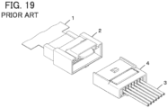
- JP 2007-214087 A discloses a connector as shown in FIG. 19 .
- This connector includes: a first connector 2 connected to an end of a sheet type conductive member 1; and a second connector 4 attached to tips of electric wires 3.
- the electric wires 3 can be connected to a flexible conductor of the sheet type conductive member 1 by fitting the second connector 4 to the first connector 2.
- first connector 2 and the second connector 4 to be fitted together are required to connect the electric wires 3 to the flexible conductor of the sheet type conductive member 1, and this causes a larger size of a device; and there is a separatable connection portion between the first connector 2 and the second connector 4, which impairs the reliability of electric connection.
- the present invention has been made to solve the conventional problem described above and aims at providing a connector and a connector assembly that can be smaller in size while reliably connecting a conductor portion of an electric wire to a flexible conductor of a sheet type conductive member.
- a connector according to the present invention is one configured to connect a conductor portion of an electric wire to a flexible conductor exposed on at least one surface of a sheet type conductive member having an opening portion, the connector comprising
- a connector assembly according to the present invention comprises:
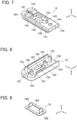
- FIGS. 1 to 4 show a connector assembly according to the embodiment.
- the connector assembly is obtained by connecting a coated electric wire 13 to a sheet type conductive member 12 by means of a connector 11.
- the sheet type conductive member 12 has a top surface and a bottom surface facing in opposite directions from each other and has a flexible conductor 12A exposed at least on the top surface.
- conductive cloth woven using a conductive thread such as silver can be used, for example.
- the flexible conductor 12A is exposed not only on the top surface but also on the bottom surface of the sheet type conductive member 12.
- one obtained by applying a conductive ink on a surface of cloth having no conductivity by printing or another method to form the flexible conductor 12A on the surface thereof can also be used as the sheet type conductive member 12.
- a member obtained by forming the flexible conductor 12A formed of a conductive pattern on a surface of an insulating sheet body such as a resin film may be used as the sheet type conductive member 12.
- the sheet type conductive member 12 has a band shape extending in a predetermined direction.
- the coated electric wire 13 has a structure in which an outer periphery of a conductor portion to be described later is covered with an insulation coating portion. With the connector 11, the conductor portion of the coated electric wire 13 is electrically connected to the flexible conductor 12A of the sheet type conductive member 12.
- the coated electric wire 13 extends in the same direction as the direction in which the sheet type conductive member 12 of band shape extends.
- the predetermined direction in which the sheet type conductive member 12 extends toward the connector 11 is called “-Y direction,” the width direction of the sheet type conductive member 12 of band shape “X direction,” and the direction orthogonal to an XY plane “Z direction.”
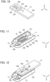
- FIGS. 5 and 6 show assembly views of the connector assembly.
- the connector assembly includes a first insulator 14 and a second insulator 15.
- the sheet type conductive member 12 is disposed on the +Z direction side of the first insulator 14 via a first adhesive sheet 16, and a conductor portion 13A exposed from an insulation coating portion 13B of the coated electric wire 13 is disposed on the +Z direction side of the sheet type conductive member 12.
- the conductor portion 13A of the coated electric wire 13 may be a so-called solid wire that is formed of one conductor or a so-called stranded wire that is formed by twisting a plurality of conductors.
- a contact force ensuring member 18 is disposed on the +Z direction side of the conductor portion 13A of the coated electric wire 13 via a second adhesive sheet 17, and the second insulator 15 is disposed on the +Z direction side of the contact force ensuring member 18.
- the first insulator 14, the first adhesive sheet 16, the second adhesive sheet 17, the contact force ensuring member 18, and the second insulator 15 constitute the connector 11.
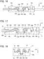
- the first insulator 14 includes a flat plate portion 14A of substantially rectangular shape extending along an XY plane, and a +Z directional surface of the flat plate portion 14A forms a first retaining surface 14B of flat shape.
- the first retaining surface 14B is provided at its center with a recessed portion 14C recessed in the -Z direction.
- the recessed portion 14C is provided at its center with a projection 14D of substantially prismatic shape projecting toward the +Z direction.
- the projection 14D projects higher than the first retaining surface 14B in the +Z direction.
- an insertion groove 14E is formed to extend in the -Y direction from the recessed portion 14C, and at a -Y directional end portion of the insertion groove 14E, an insertion groove 14F is formed with a larger groove width than that of the insertion groove 14E.
- an insertion hole 14G of recess shape is formed to communicate with the recessed portion 14C.
- the flat plate portion 14A includes three through-holes 14H separately formed on opposite sides of the insertion groove 14E in the X direction and on the +Y direction side of the insertion hole 14G, the through-holes 14H penetrating the flat plate portion 14A in the Z direction.
- step portions 14J extending in the Y direction are separately formed at X-directional opposite lateral surfaces of the flat plate portion 14A.
- the second insulator 15 includes a flat plate portion 15A of substantially rectangular shape extending along an XY plane, and a -Z directional surface of the flat plate portion 15A forms a second retaining surface 15B of flat shape.
- the second retaining surface 15B is provided at its center with a protrusion portion 15C jutting in the -Z direction.
- the protrusion portion 15C is provided at its center with a projection accommodating portion 15D of recess shape that is recessed in the +Z direction and is deeper than the second retaining surface 15B.
- an insertion groove 15E is formed to extend in the -Y direction, and at a -Y directional end portion of the insertion groove 15E, an insertion groove 15F is formed with a larger groove width than that of the insertion groove 15E.
- a tip retaining portion 15G of columnar shape is formed to protrude in the -Z direction from the second retaining surface 15B, and a slit 15H is formed in the tip retaining portion 15G to extend in the Y direction so as to divide the tip retaining portion 15G in two in the X direction.
- the tip retaining portion 15G is to retain a tip of the conductor portion 13A of the coated electric wire 13, and the slit 15H has a slit width slightly smaller than the diameter of the conductor portion 13A of the coated electric wire 13 and is configured such that the conductor portion 13A may be inserted thereinto.
- the flat plate portion 15A includes three bosses 15J separately formed on opposite sides of the insertion groove 15E in the X direction and on the +Y direction side of the tip retaining portion 15G, the bosses 15J protruding in the -Z direction.
- the insertion groove 14E of the first insulator 14 and the insertion groove 15E of the second insulator 15 work together to retain the conductor portion 13A of the coated electric wire 13
- the insertion groove 14F of the first insulator 14 and the insertion groove 15F of the second insulator 15 work together to retain the insulation coating portion 13B of the coated electric wire 13 so as to constitute an insulation coat retaining portion.
- the contact force ensuring member 18 is to ensure a contact force between the conductor portion 13A of the coated electric wire 13 and the flexible conductor 12A of the sheet type conductive member 12.
- the contact force ensuring member 18 is formed of a metal sheet being bent and includes a projection penetrating hole 18A which the projection 14D of the first insulator 14 penetrates, and a pair of pressing portions 18B facing each other in the Y direction across the projection penetrating hole 18A and protruding in the +Z direction.
- the second adhesive sheet 17 is disposed on the second retaining surface 15B of the second insulator 15.
- the second adhesive sheet 17 has an opening portion corresponding to the protrusion portion 15C and the tip retaining portion 15G of the second insulator 15 and three opening portions separately corresponding to the three bosses 15J.
- the second adhesive sheet 17 is disposed on the second retaining surface 15B in the state where the protrusion portion 15C, the tip retaining portion 15G, and the three bosses 15J penetrate through these opening portions.
- the intensity of the first insulator 14 and the second insulator 15 can be ensured, and even when an external force is applied to the connector 11 via the coated electric wire 13 or the sheet type conductive member 12, the occurrence of breakage or the like can be avoided.
- the tip retaining portion 15G for retaining the tip of the conductor portion 13A of the coated electric wire 13 is formed in the second insulator 15, the tip retaining portion may be formed in the first insulator 14.
- the pair of pressing portions 18B of the contact force ensuring member 18 is inserted in the projection accommodating portion 15D of the second insulator 15, and each projecting portion 12C of the sheet type conductive member 12 and the conductor portion 13A of the coated electric wire 13 are held between the outer lateral surface of the projection 14D and the corresponding pressing portion 18B of the contact force ensuring member 18, but the invention is not limited thereto.
- the conductor portion 13A of the coated electric wire 13 can be brought into contact with and electrically connected to the flexible conductor 12A exposed on the top surface of the projecting portion 12C of the sheet type conductive member 12.
- the contact force ensuring member 18 is preferably used because a contact force between the conductor portion 13A of the coated electric wire 13 and the flexible conductor 12A of the sheet type conductive member 12 is reliably ensured.
- coated electric wire 13 is used as an electric wire to be connected to the sheet type conductive member 12 in the embodiment described above, an electric wire formed of only the conductor portion 13A whose outer periphery is not covered with the insulation coating portion 13B made of an insulating material may also be connected to the sheet type conductive member 12.
- one projection 14D formed in the first insulator 14 is accommodated in one projection accommodating portion 15D formed in the second insulator 15 to thereby connect the conductor portion 13A of one coated electric wire 13 to the flexible conductor 12A of one sheet type conductive member 12, but the connector can be configured such that, using the first insulator having a plurality of projections and the second insulator having a plurality of projection accommodating portions, conductor portions of a plurality of electric wires are connected to flexible conductors of a plurality of sheet type conductive members in a similar manner.
Landscapes
- Coupling Device And Connection With Printed Circuit (AREA)
- Connections Effected By Soldering, Adhesion, Or Permanent Deformation (AREA)
Applications Claiming Priority (1)
| Application Number | Priority Date | Filing Date | Title |
|---|---|---|---|
| JP2023097412A JP2024178974A (ja) | 2023-06-14 | 2023-06-14 | コネクタおよびコネクタ組立体 |
Publications (2)
| Publication Number | Publication Date |
|---|---|
| EP4478554A1 true EP4478554A1 (de) | 2024-12-18 |
| EP4478554B1 EP4478554B1 (de) | 2025-05-14 |
Family
ID=91129032
Family Applications (1)
| Application Number | Title | Priority Date | Filing Date |
|---|---|---|---|
| EP24173989.5A Active EP4478554B1 (de) | 2023-06-14 | 2024-05-03 | Verbinder und verbinderanordnung |
Country Status (4)
| Country | Link |
|---|---|
| US (1) | US20240421504A1 (de) |
| EP (1) | EP4478554B1 (de) |
| JP (1) | JP2024178974A (de) |
| CN (1) | CN119153999A (de) |
Citations (6)
| Publication number | Priority date | Publication date | Assignee | Title |
|---|---|---|---|---|
| JPS52147261U (de) * | 1976-05-01 | 1977-11-08 | ||
| WO2004109862A1 (en) * | 2003-05-30 | 2004-12-16 | 3M Innovative Properties Company | Wire connection structure and connector |
| JP2007214087A (ja) | 2006-02-13 | 2007-08-23 | Fujikura Ltd | コネクタ |
| JP2008270006A (ja) * | 2007-04-23 | 2008-11-06 | Yazaki Corp | フラットケーブルの接続方法 |
| EP3800739A1 (de) * | 2019-10-03 | 2021-04-07 | Japan Aviation Electronics Industry, Ltd. | Verbinder und verbindungsverfahren |
| EP4120480A1 (de) * | 2021-07-14 | 2023-01-18 | Japan Aviation Electronics Industry, Ltd. | Steckverbinder und steckverbinderanordnung |
-
2023
- 2023-06-14 JP JP2023097412A patent/JP2024178974A/ja active Pending
-
2024
- 2024-04-02 CN CN202410396545.2A patent/CN119153999A/zh active Pending
- 2024-04-15 US US18/635,517 patent/US20240421504A1/en active Pending
- 2024-05-03 EP EP24173989.5A patent/EP4478554B1/de active Active
Patent Citations (6)
| Publication number | Priority date | Publication date | Assignee | Title |
|---|---|---|---|---|
| JPS52147261U (de) * | 1976-05-01 | 1977-11-08 | ||
| WO2004109862A1 (en) * | 2003-05-30 | 2004-12-16 | 3M Innovative Properties Company | Wire connection structure and connector |
| JP2007214087A (ja) | 2006-02-13 | 2007-08-23 | Fujikura Ltd | コネクタ |
| JP2008270006A (ja) * | 2007-04-23 | 2008-11-06 | Yazaki Corp | フラットケーブルの接続方法 |
| EP3800739A1 (de) * | 2019-10-03 | 2021-04-07 | Japan Aviation Electronics Industry, Ltd. | Verbinder und verbindungsverfahren |
| EP4120480A1 (de) * | 2021-07-14 | 2023-01-18 | Japan Aviation Electronics Industry, Ltd. | Steckverbinder und steckverbinderanordnung |
Also Published As
| Publication number | Publication date |
|---|---|
| US20240421504A1 (en) | 2024-12-19 |
| JP2024178974A (ja) | 2024-12-26 |
| EP4478554B1 (de) | 2025-05-14 |
| CN119153999A (zh) | 2024-12-17 |
Similar Documents
| Publication | Publication Date | Title |
|---|---|---|
| EP3361575B1 (de) | Verbinder | |
| EP3376601B1 (de) | Verbinder | |
| EP4000436B1 (de) | Verbinder | |
| EP4340135B1 (de) | Verbinder | |
| EP3696918B1 (de) | Verbindungsverfahren, verbindungsstruktur und verbindungsanschluss | |
| JP4084292B2 (ja) | 同軸ケーブルの圧接構造 | |
| US12230907B2 (en) | Electrical connector for connecting an electric wire to a flat flexible conductor and an electrical connector assembly therefor | |
| EP4478554B1 (de) | Verbinder und verbinderanordnung | |
| US10862254B2 (en) | Coated conductive wire connecting method, coated conductive wire connecting structure and coated conductive wire connecting member | |
| EP4462605B1 (de) | Verbinder | |
| EP4379964A1 (de) | Verbinderanordnung und verbindungsverfahren | |
| EP4343974A1 (de) | Verbinder | |
| US20240088590A1 (en) | Connector | |
| EP4346013A1 (de) | Verbinder, verbinderanordnung und verbindungsverfahren | |
| US20240145955A1 (en) | Connector and connector assembly | |
| EP4387004A1 (de) | Verbinder |
Legal Events
| Date | Code | Title | Description |
|---|---|---|---|
| PUAI | Public reference made under article 153(3) epc to a published international application that has entered the european phase |
Free format text: ORIGINAL CODE: 0009012 |
|
| STAA | Information on the status of an ep patent application or granted ep patent |
Free format text: STATUS: REQUEST FOR EXAMINATION WAS MADE |
|
| 17P | Request for examination filed |
Effective date: 20240503 |
|
| AK | Designated contracting states |
Kind code of ref document: A1 Designated state(s): AL AT BE BG CH CY CZ DE DK EE ES FI FR GB GR HR HU IE IS IT LI LT LU LV MC ME MK MT NL NO PL PT RO RS SE SI SK SM TR |
|
| GRAP | Despatch of communication of intention to grant a patent |
Free format text: ORIGINAL CODE: EPIDOSNIGR1 |
|
| STAA | Information on the status of an ep patent application or granted ep patent |
Free format text: STATUS: GRANT OF PATENT IS INTENDED |
|
| RIC1 | Information provided on ipc code assigned before grant |
Ipc: H01R 4/06 20060101ALI20250224BHEP Ipc: H01R 12/59 20110101ALI20250224BHEP Ipc: H01R 12/63 20110101AFI20250224BHEP |
|
| GRAS | Grant fee paid |
Free format text: ORIGINAL CODE: EPIDOSNIGR3 |
|
| INTG | Intention to grant announced |
Effective date: 20250311 |
|
| GRAA | (expected) grant |
Free format text: ORIGINAL CODE: 0009210 |
|
| STAA | Information on the status of an ep patent application or granted ep patent |
Free format text: STATUS: THE PATENT HAS BEEN GRANTED |
|
| AK | Designated contracting states |
Kind code of ref document: B1 Designated state(s): AL AT BE BG CH CY CZ DE DK EE ES FI FR GB GR HR HU IE IS IT LI LT LU LV MC ME MK MT NL NO PL PT RO RS SE SI SK SM TR |
|
| REG | Reference to a national code |
Ref country code: GB Ref legal event code: FG4D |
|
| REG | Reference to a national code |
Ref country code: CH Ref legal event code: EP |
|
| REG | Reference to a national code |
Ref country code: IE Ref legal event code: FG4D |
|
| REG | Reference to a national code |
Ref country code: DE Ref legal event code: R096 Ref document number: 602024000129 Country of ref document: DE |
|
| REG | Reference to a national code |
Ref country code: NL Ref legal event code: MP Effective date: 20250514 |
|
| PG25 | Lapsed in a contracting state [announced via postgrant information from national office to epo] |
Ref country code: FI Free format text: LAPSE BECAUSE OF FAILURE TO SUBMIT A TRANSLATION OF THE DESCRIPTION OR TO PAY THE FEE WITHIN THE PRESCRIBED TIME-LIMIT Effective date: 20250514 Ref country code: PT Free format text: LAPSE BECAUSE OF FAILURE TO SUBMIT A TRANSLATION OF THE DESCRIPTION OR TO PAY THE FEE WITHIN THE PRESCRIBED TIME-LIMIT Effective date: 20250915 Ref country code: ES Free format text: LAPSE BECAUSE OF FAILURE TO SUBMIT A TRANSLATION OF THE DESCRIPTION OR TO PAY THE FEE WITHIN THE PRESCRIBED TIME-LIMIT Effective date: 20250514 |
|
| REG | Reference to a national code |
Ref country code: LT Ref legal event code: MG9D |
|
| PG25 | Lapsed in a contracting state [announced via postgrant information from national office to epo] |
Ref country code: NO Free format text: LAPSE BECAUSE OF FAILURE TO SUBMIT A TRANSLATION OF THE DESCRIPTION OR TO PAY THE FEE WITHIN THE PRESCRIBED TIME-LIMIT Effective date: 20250814 Ref country code: GR Free format text: LAPSE BECAUSE OF FAILURE TO SUBMIT A TRANSLATION OF THE DESCRIPTION OR TO PAY THE FEE WITHIN THE PRESCRIBED TIME-LIMIT Effective date: 20250815 |
|
| PG25 | Lapsed in a contracting state [announced via postgrant information from national office to epo] |
Ref country code: PL Free format text: LAPSE BECAUSE OF FAILURE TO SUBMIT A TRANSLATION OF THE DESCRIPTION OR TO PAY THE FEE WITHIN THE PRESCRIBED TIME-LIMIT Effective date: 20250514 Ref country code: NL Free format text: LAPSE BECAUSE OF FAILURE TO SUBMIT A TRANSLATION OF THE DESCRIPTION OR TO PAY THE FEE WITHIN THE PRESCRIBED TIME-LIMIT Effective date: 20250514 |
|
| REG | Reference to a national code |
Ref country code: AT Ref legal event code: MK05 Ref document number: 1795640 Country of ref document: AT Kind code of ref document: T Effective date: 20250514 |
|
| PG25 | Lapsed in a contracting state [announced via postgrant information from national office to epo] |
Ref country code: BG Free format text: LAPSE BECAUSE OF FAILURE TO SUBMIT A TRANSLATION OF THE DESCRIPTION OR TO PAY THE FEE WITHIN THE PRESCRIBED TIME-LIMIT Effective date: 20250514 |
|
| PG25 | Lapsed in a contracting state [announced via postgrant information from national office to epo] |
Ref country code: HR Free format text: LAPSE BECAUSE OF FAILURE TO SUBMIT A TRANSLATION OF THE DESCRIPTION OR TO PAY THE FEE WITHIN THE PRESCRIBED TIME-LIMIT Effective date: 20250514 |
|
| PG25 | Lapsed in a contracting state [announced via postgrant information from national office to epo] |
Ref country code: AT Free format text: LAPSE BECAUSE OF FAILURE TO SUBMIT A TRANSLATION OF THE DESCRIPTION OR TO PAY THE FEE WITHIN THE PRESCRIBED TIME-LIMIT Effective date: 20250514 |
|
| PG25 | Lapsed in a contracting state [announced via postgrant information from national office to epo] |
Ref country code: RS Free format text: LAPSE BECAUSE OF FAILURE TO SUBMIT A TRANSLATION OF THE DESCRIPTION OR TO PAY THE FEE WITHIN THE PRESCRIBED TIME-LIMIT Effective date: 20250814 |
|
| PG25 | Lapsed in a contracting state [announced via postgrant information from national office to epo] |
Ref country code: IS Free format text: LAPSE BECAUSE OF FAILURE TO SUBMIT A TRANSLATION OF THE DESCRIPTION OR TO PAY THE FEE WITHIN THE PRESCRIBED TIME-LIMIT Effective date: 20250914 |
|
| PG25 | Lapsed in a contracting state [announced via postgrant information from national office to epo] |
Ref country code: LV Free format text: LAPSE BECAUSE OF FAILURE TO SUBMIT A TRANSLATION OF THE DESCRIPTION OR TO PAY THE FEE WITHIN THE PRESCRIBED TIME-LIMIT Effective date: 20250514 |
|
| PG25 | Lapsed in a contracting state [announced via postgrant information from national office to epo] |
Ref country code: DK Free format text: LAPSE BECAUSE OF FAILURE TO SUBMIT A TRANSLATION OF THE DESCRIPTION OR TO PAY THE FEE WITHIN THE PRESCRIBED TIME-LIMIT Effective date: 20250514 Ref country code: SM Free format text: LAPSE BECAUSE OF FAILURE TO SUBMIT A TRANSLATION OF THE DESCRIPTION OR TO PAY THE FEE WITHIN THE PRESCRIBED TIME-LIMIT Effective date: 20250514 |
|
| PG25 | Lapsed in a contracting state [announced via postgrant information from national office to epo] |
Ref country code: CZ Free format text: LAPSE BECAUSE OF FAILURE TO SUBMIT A TRANSLATION OF THE DESCRIPTION OR TO PAY THE FEE WITHIN THE PRESCRIBED TIME-LIMIT Effective date: 20250514 |
|
| PG25 | Lapsed in a contracting state [announced via postgrant information from national office to epo] |
Ref country code: EE Free format text: LAPSE BECAUSE OF FAILURE TO SUBMIT A TRANSLATION OF THE DESCRIPTION OR TO PAY THE FEE WITHIN THE PRESCRIBED TIME-LIMIT Effective date: 20250514 |
|
| PG25 | Lapsed in a contracting state [announced via postgrant information from national office to epo] |
Ref country code: SK Free format text: LAPSE BECAUSE OF FAILURE TO SUBMIT A TRANSLATION OF THE DESCRIPTION OR TO PAY THE FEE WITHIN THE PRESCRIBED TIME-LIMIT Effective date: 20250514 |
|
| PG25 | Lapsed in a contracting state [announced via postgrant information from national office to epo] |
Ref country code: IT Free format text: LAPSE BECAUSE OF FAILURE TO SUBMIT A TRANSLATION OF THE DESCRIPTION OR TO PAY THE FEE WITHIN THE PRESCRIBED TIME-LIMIT Effective date: 20250514 |
|
| PLBE | No opposition filed within time limit |
Free format text: ORIGINAL CODE: 0009261 |
|
| STAA | Information on the status of an ep patent application or granted ep patent |
Free format text: STATUS: NO OPPOSITION FILED WITHIN TIME LIMIT |
|
| REG | Reference to a national code |
Ref country code: CH Ref legal event code: L10 Free format text: ST27 STATUS EVENT CODE: U-0-0-L10-L00 (AS PROVIDED BY THE NATIONAL OFFICE) Effective date: 20260325 |