EP4478554A1 - Connector and connector assembly - Google Patents
Connector and connector assembly Download PDFInfo
- Publication number
- EP4478554A1 EP4478554A1 EP24173989.5A EP24173989A EP4478554A1 EP 4478554 A1 EP4478554 A1 EP 4478554A1 EP 24173989 A EP24173989 A EP 24173989A EP 4478554 A1 EP4478554 A1 EP 4478554A1
- Authority
- EP
- European Patent Office
- Prior art keywords
- insulator
- conductive member
- type conductive
- electric wire
- sheet type
- Prior art date
- Legal status (The legal status is an assumption and is not a legal conclusion. Google has not performed a legal analysis and makes no representation as to the accuracy of the status listed.)
- Granted
Links
Images



Classifications
-
- H—ELECTRICITY
- H01—ELECTRIC ELEMENTS
- H01R—ELECTRICALLY-CONDUCTIVE CONNECTIONS; STRUCTURAL ASSOCIATIONS OF A PLURALITY OF MUTUALLY-INSULATED ELECTRICAL CONNECTING ELEMENTS; COUPLING DEVICES; CURRENT COLLECTORS
- H01R12/00—Structural associations of a plurality of mutually-insulated electrical connecting elements, specially adapted for printed circuits, e.g. printed circuit boards [PCB], flat or ribbon cables, or like generally planar structures, e.g. terminal strips, terminal blocks; Coupling devices specially adapted for printed circuits, flat or ribbon cables, or like generally planar structures; Terminals specially adapted for contact with, or insertion into, printed circuits, flat or ribbon cables, or like generally planar structures
- H01R12/50—Fixed connections
- H01R12/59—Fixed connections for flexible printed circuits, flat or ribbon cables or like structures
- H01R12/63—Fixed connections for flexible printed circuits, flat or ribbon cables or like structures connecting to another shape cable
-
- H—ELECTRICITY
- H01—ELECTRIC ELEMENTS
- H01R—ELECTRICALLY-CONDUCTIVE CONNECTIONS; STRUCTURAL ASSOCIATIONS OF A PLURALITY OF MUTUALLY-INSULATED ELECTRICAL CONNECTING ELEMENTS; COUPLING DEVICES; CURRENT COLLECTORS
- H01R13/00—Details of coupling devices of the kinds covered by groups H01R12/70 or H01R24/00 - H01R33/00
- H01R13/58—Means for relieving strain on wire connection, e.g. cord grip, for avoiding loosening of connections between wires and terminals within a coupling device terminating a cable
- H01R13/5804—Means for relieving strain on wire connection, e.g. cord grip, for avoiding loosening of connections between wires and terminals within a coupling device terminating a cable comprising a separate cable clamping part
-
- H—ELECTRICITY
- H01—ELECTRIC ELEMENTS
- H01R—ELECTRICALLY-CONDUCTIVE CONNECTIONS; STRUCTURAL ASSOCIATIONS OF A PLURALITY OF MUTUALLY-INSULATED ELECTRICAL CONNECTING ELEMENTS; COUPLING DEVICES; CURRENT COLLECTORS
- H01R12/00—Structural associations of a plurality of mutually-insulated electrical connecting elements, specially adapted for printed circuits, e.g. printed circuit boards [PCB], flat or ribbon cables, or like generally planar structures, e.g. terminal strips, terminal blocks; Coupling devices specially adapted for printed circuits, flat or ribbon cables, or like generally planar structures; Terminals specially adapted for contact with, or insertion into, printed circuits, flat or ribbon cables, or like generally planar structures
- H01R12/50—Fixed connections
- H01R12/59—Fixed connections for flexible printed circuits, flat or ribbon cables or like structures
- H01R12/592—Fixed connections for flexible printed circuits, flat or ribbon cables or like structures connections to contact elements
-
- H—ELECTRICITY
- H01—ELECTRIC ELEMENTS
- H01R—ELECTRICALLY-CONDUCTIVE CONNECTIONS; STRUCTURAL ASSOCIATIONS OF A PLURALITY OF MUTUALLY-INSULATED ELECTRICAL CONNECTING ELEMENTS; COUPLING DEVICES; CURRENT COLLECTORS
- H01R13/00—Details of coupling devices of the kinds covered by groups H01R12/70 or H01R24/00 - H01R33/00
- H01R13/02—Contact members
- H01R13/22—Contacts for co-operating by abutting
- H01R13/24—Contacts for co-operating by abutting resilient; resiliently-mounted
- H01R13/2407—Contacts for co-operating by abutting resilient; resiliently-mounted characterized by the resilient means
- H01R13/2414—Contacts for co-operating by abutting resilient; resiliently-mounted characterized by the resilient means conductive elastomers
-
- H—ELECTRICITY
- H01—ELECTRIC ELEMENTS
- H01R—ELECTRICALLY-CONDUCTIVE CONNECTIONS; STRUCTURAL ASSOCIATIONS OF A PLURALITY OF MUTUALLY-INSULATED ELECTRICAL CONNECTING ELEMENTS; COUPLING DEVICES; CURRENT COLLECTORS
- H01R13/00—Details of coupling devices of the kinds covered by groups H01R12/70 or H01R24/00 - H01R33/00
- H01R13/40—Securing contact members in or to a base or case; Insulating of contact members
- H01R13/405—Securing in non-demountable manner, e.g. moulding, riveting
- H01R13/41—Securing in non-demountable manner, e.g. moulding, riveting by frictional grip in grommet, panel or base
-
- H—ELECTRICITY
- H01—ELECTRIC ELEMENTS
- H01R—ELECTRICALLY-CONDUCTIVE CONNECTIONS; STRUCTURAL ASSOCIATIONS OF A PLURALITY OF MUTUALLY-INSULATED ELECTRICAL CONNECTING ELEMENTS; COUPLING DEVICES; CURRENT COLLECTORS
- H01R13/00—Details of coupling devices of the kinds covered by groups H01R12/70 or H01R24/00 - H01R33/00
- H01R13/46—Bases; Cases
- H01R13/502—Bases; Cases composed of different pieces
- H01R13/504—Bases; Cases composed of different pieces different pieces being moulded, cemented, welded, e.g. ultrasonic welding, or swaged together
-
- H—ELECTRICITY
- H01—ELECTRIC ELEMENTS
- H01R—ELECTRICALLY-CONDUCTIVE CONNECTIONS; STRUCTURAL ASSOCIATIONS OF A PLURALITY OF MUTUALLY-INSULATED ELECTRICAL CONNECTING ELEMENTS; COUPLING DEVICES; CURRENT COLLECTORS
- H01R13/00—Details of coupling devices of the kinds covered by groups H01R12/70 or H01R24/00 - H01R33/00
- H01R13/62—Means for facilitating engagement or disengagement of coupling parts or for holding them in engagement
- H01R13/639—Additional means for holding or locking coupling parts together, after engagement, e.g. separate keylock, retainer strap
-
- H—ELECTRICITY
- H01—ELECTRIC ELEMENTS
- H01R—ELECTRICALLY-CONDUCTIVE CONNECTIONS; STRUCTURAL ASSOCIATIONS OF A PLURALITY OF MUTUALLY-INSULATED ELECTRICAL CONNECTING ELEMENTS; COUPLING DEVICES; CURRENT COLLECTORS
- H01R4/00—Electrically-conductive connections between two or more conductive members in direct contact, i.e. touching one another; Means for effecting or maintaining such contact; Electrically-conductive connections having two or more spaced connecting locations for conductors and using contact members penetrating insulation
- H01R4/06—Riveted connections
-
- H—ELECTRICITY
- H01—ELECTRIC ELEMENTS
- H01R—ELECTRICALLY-CONDUCTIVE CONNECTIONS; STRUCTURAL ASSOCIATIONS OF A PLURALITY OF MUTUALLY-INSULATED ELECTRICAL CONNECTING ELEMENTS; COUPLING DEVICES; CURRENT COLLECTORS
- H01R4/00—Electrically-conductive connections between two or more conductive members in direct contact, i.e. touching one another; Means for effecting or maintaining such contact; Electrically-conductive connections having two or more spaced connecting locations for conductors and using contact members penetrating insulation
- H01R4/10—Electrically-conductive connections between two or more conductive members in direct contact, i.e. touching one another; Means for effecting or maintaining such contact; Electrically-conductive connections having two or more spaced connecting locations for conductors and using contact members penetrating insulation effected solely by twisting, wrapping, bending, crimping, or other permanent deformation
- H01R4/16—Electrically-conductive connections between two or more conductive members in direct contact, i.e. touching one another; Means for effecting or maintaining such contact; Electrically-conductive connections having two or more spaced connecting locations for conductors and using contact members penetrating insulation effected solely by twisting, wrapping, bending, crimping, or other permanent deformation by bending
Definitions
- the present invention relates to a connector, particularly to a connector connecting a conductor portion of an electric wire to a flexible conductor of a sheet type conductive member.
- the present invention also relates to a connector assembly in which a conductor portion of an electric wire is connected to a flexible conductor of a sheet type conductive member by means of the connector.
- the electrode and the wearable device can be interconnected by, for instance, use of a connector connected to the flexible conductor.
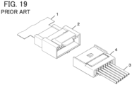
- JP 2007-214087 A discloses a connector as shown in FIG. 19 .
- This connector includes: a first connector 2 connected to an end of a sheet type conductive member 1; and a second connector 4 attached to tips of electric wires 3.
- the electric wires 3 can be connected to a flexible conductor of the sheet type conductive member 1 by fitting the second connector 4 to the first connector 2.
- first connector 2 and the second connector 4 to be fitted together are required to connect the electric wires 3 to the flexible conductor of the sheet type conductive member 1, and this causes a larger size of a device; and there is a separatable connection portion between the first connector 2 and the second connector 4, which impairs the reliability of electric connection.
- the present invention has been made to solve the conventional problem described above and aims at providing a connector and a connector assembly that can be smaller in size while reliably connecting a conductor portion of an electric wire to a flexible conductor of a sheet type conductive member.
- a connector according to the present invention is one configured to connect a conductor portion of an electric wire to a flexible conductor exposed on at least one surface of a sheet type conductive member having an opening portion, the connector comprising
- a connector assembly according to the present invention comprises:
- FIGS. 1 to 4 show a connector assembly according to the embodiment.
- the connector assembly is obtained by connecting a coated electric wire 13 to a sheet type conductive member 12 by means of a connector 11.
- the sheet type conductive member 12 has a top surface and a bottom surface facing in opposite directions from each other and has a flexible conductor 12A exposed at least on the top surface.
- conductive cloth woven using a conductive thread such as silver can be used, for example.
- the flexible conductor 12A is exposed not only on the top surface but also on the bottom surface of the sheet type conductive member 12.
- one obtained by applying a conductive ink on a surface of cloth having no conductivity by printing or another method to form the flexible conductor 12A on the surface thereof can also be used as the sheet type conductive member 12.
- a member obtained by forming the flexible conductor 12A formed of a conductive pattern on a surface of an insulating sheet body such as a resin film may be used as the sheet type conductive member 12.
- the sheet type conductive member 12 has a band shape extending in a predetermined direction.
- the coated electric wire 13 has a structure in which an outer periphery of a conductor portion to be described later is covered with an insulation coating portion. With the connector 11, the conductor portion of the coated electric wire 13 is electrically connected to the flexible conductor 12A of the sheet type conductive member 12.
- the coated electric wire 13 extends in the same direction as the direction in which the sheet type conductive member 12 of band shape extends.
- the predetermined direction in which the sheet type conductive member 12 extends toward the connector 11 is called “-Y direction,” the width direction of the sheet type conductive member 12 of band shape “X direction,” and the direction orthogonal to an XY plane “Z direction.”
- FIGS. 5 and 6 show assembly views of the connector assembly.
- the connector assembly includes a first insulator 14 and a second insulator 15.
- the sheet type conductive member 12 is disposed on the +Z direction side of the first insulator 14 via a first adhesive sheet 16, and a conductor portion 13A exposed from an insulation coating portion 13B of the coated electric wire 13 is disposed on the +Z direction side of the sheet type conductive member 12.
- the conductor portion 13A of the coated electric wire 13 may be a so-called solid wire that is formed of one conductor or a so-called stranded wire that is formed by twisting a plurality of conductors.
- a contact force ensuring member 18 is disposed on the +Z direction side of the conductor portion 13A of the coated electric wire 13 via a second adhesive sheet 17, and the second insulator 15 is disposed on the +Z direction side of the contact force ensuring member 18.
- the first insulator 14, the first adhesive sheet 16, the second adhesive sheet 17, the contact force ensuring member 18, and the second insulator 15 constitute the connector 11.
- the first insulator 14 includes a flat plate portion 14A of substantially rectangular shape extending along an XY plane, and a +Z directional surface of the flat plate portion 14A forms a first retaining surface 14B of flat shape.
- the first retaining surface 14B is provided at its center with a recessed portion 14C recessed in the -Z direction.
- the recessed portion 14C is provided at its center with a projection 14D of substantially prismatic shape projecting toward the +Z direction.
- the projection 14D projects higher than the first retaining surface 14B in the +Z direction.
- an insertion groove 14E is formed to extend in the -Y direction from the recessed portion 14C, and at a -Y directional end portion of the insertion groove 14E, an insertion groove 14F is formed with a larger groove width than that of the insertion groove 14E.
- an insertion hole 14G of recess shape is formed to communicate with the recessed portion 14C.
- the flat plate portion 14A includes three through-holes 14H separately formed on opposite sides of the insertion groove 14E in the X direction and on the +Y direction side of the insertion hole 14G, the through-holes 14H penetrating the flat plate portion 14A in the Z direction.
- step portions 14J extending in the Y direction are separately formed at X-directional opposite lateral surfaces of the flat plate portion 14A.
- the second insulator 15 includes a flat plate portion 15A of substantially rectangular shape extending along an XY plane, and a -Z directional surface of the flat plate portion 15A forms a second retaining surface 15B of flat shape.
- the second retaining surface 15B is provided at its center with a protrusion portion 15C jutting in the -Z direction.
- the protrusion portion 15C is provided at its center with a projection accommodating portion 15D of recess shape that is recessed in the +Z direction and is deeper than the second retaining surface 15B.
- an insertion groove 15E is formed to extend in the -Y direction, and at a -Y directional end portion of the insertion groove 15E, an insertion groove 15F is formed with a larger groove width than that of the insertion groove 15E.
- a tip retaining portion 15G of columnar shape is formed to protrude in the -Z direction from the second retaining surface 15B, and a slit 15H is formed in the tip retaining portion 15G to extend in the Y direction so as to divide the tip retaining portion 15G in two in the X direction.
- the tip retaining portion 15G is to retain a tip of the conductor portion 13A of the coated electric wire 13, and the slit 15H has a slit width slightly smaller than the diameter of the conductor portion 13A of the coated electric wire 13 and is configured such that the conductor portion 13A may be inserted thereinto.
- the flat plate portion 15A includes three bosses 15J separately formed on opposite sides of the insertion groove 15E in the X direction and on the +Y direction side of the tip retaining portion 15G, the bosses 15J protruding in the -Z direction.
- the insertion groove 14E of the first insulator 14 and the insertion groove 15E of the second insulator 15 work together to retain the conductor portion 13A of the coated electric wire 13
- the insertion groove 14F of the first insulator 14 and the insertion groove 15F of the second insulator 15 work together to retain the insulation coating portion 13B of the coated electric wire 13 so as to constitute an insulation coat retaining portion.
- the contact force ensuring member 18 is to ensure a contact force between the conductor portion 13A of the coated electric wire 13 and the flexible conductor 12A of the sheet type conductive member 12.
- the contact force ensuring member 18 is formed of a metal sheet being bent and includes a projection penetrating hole 18A which the projection 14D of the first insulator 14 penetrates, and a pair of pressing portions 18B facing each other in the Y direction across the projection penetrating hole 18A and protruding in the +Z direction.
- the second adhesive sheet 17 is disposed on the second retaining surface 15B of the second insulator 15.
- the second adhesive sheet 17 has an opening portion corresponding to the protrusion portion 15C and the tip retaining portion 15G of the second insulator 15 and three opening portions separately corresponding to the three bosses 15J.
- the second adhesive sheet 17 is disposed on the second retaining surface 15B in the state where the protrusion portion 15C, the tip retaining portion 15G, and the three bosses 15J penetrate through these opening portions.
- the intensity of the first insulator 14 and the second insulator 15 can be ensured, and even when an external force is applied to the connector 11 via the coated electric wire 13 or the sheet type conductive member 12, the occurrence of breakage or the like can be avoided.
- the tip retaining portion 15G for retaining the tip of the conductor portion 13A of the coated electric wire 13 is formed in the second insulator 15, the tip retaining portion may be formed in the first insulator 14.
- the pair of pressing portions 18B of the contact force ensuring member 18 is inserted in the projection accommodating portion 15D of the second insulator 15, and each projecting portion 12C of the sheet type conductive member 12 and the conductor portion 13A of the coated electric wire 13 are held between the outer lateral surface of the projection 14D and the corresponding pressing portion 18B of the contact force ensuring member 18, but the invention is not limited thereto.
- the conductor portion 13A of the coated electric wire 13 can be brought into contact with and electrically connected to the flexible conductor 12A exposed on the top surface of the projecting portion 12C of the sheet type conductive member 12.
- the contact force ensuring member 18 is preferably used because a contact force between the conductor portion 13A of the coated electric wire 13 and the flexible conductor 12A of the sheet type conductive member 12 is reliably ensured.
- coated electric wire 13 is used as an electric wire to be connected to the sheet type conductive member 12 in the embodiment described above, an electric wire formed of only the conductor portion 13A whose outer periphery is not covered with the insulation coating portion 13B made of an insulating material may also be connected to the sheet type conductive member 12.
- one projection 14D formed in the first insulator 14 is accommodated in one projection accommodating portion 15D formed in the second insulator 15 to thereby connect the conductor portion 13A of one coated electric wire 13 to the flexible conductor 12A of one sheet type conductive member 12, but the connector can be configured such that, using the first insulator having a plurality of projections and the second insulator having a plurality of projection accommodating portions, conductor portions of a plurality of electric wires are connected to flexible conductors of a plurality of sheet type conductive members in a similar manner.
Landscapes
- Coupling Device And Connection With Printed Circuit (AREA)
- Connections Effected By Soldering, Adhesion, Or Permanent Deformation (AREA)
Abstract
Description
- The present invention relates to a connector, particularly to a connector connecting a conductor portion of an electric wire to a flexible conductor of a sheet type conductive member.
- The present invention also relates to a connector assembly in which a conductor portion of an electric wire is connected to a flexible conductor of a sheet type conductive member by means of the connector.
- In recent years, attention has been drawn to so-called smart clothes that can obtain user's biological data such as the heart rate and the body temperature only by being worn by the user. Such smart clothes have an electrode disposed at a measurement site and constituted of a flexible conductor, and when a wearable device serving as a measurement device is electrically connected to the electrode, biological data can be transmitted to the wearable device.
- The electrode and the wearable device can be interconnected by, for instance, use of a connector connected to the flexible conductor.
- However, when the wearable device is situated away from the measurement site, it is necessary to provide an electric path connecting the electrode disposed at the measurement site to the place where the connector is attached, and if such an electric path is formed from a flexible conductor, this causes higher electric resistance and higher cost.
- To interconnect an electrode constituted of a flexible conductor and a wearable device by use of an electric wire that has low electric resistance and is inexpensive, it has been desired to develop a small-sized connector connecting the electric wire to the flexible conductor disposed on a garment.
- As a connector for connecting an electric wire to a flexible conductor, for instance,
JP 2007-214087 A FIG. 19 . This connector includes: afirst connector 2 connected to an end of a sheet typeconductive member 1; and a second connector 4 attached to tips ofelectric wires 3. Theelectric wires 3 can be connected to a flexible conductor of the sheet typeconductive member 1 by fitting the second connector 4 to thefirst connector 2. - However, the
first connector 2 and the second connector 4 to be fitted together are required to connect theelectric wires 3 to the flexible conductor of the sheet typeconductive member 1, and this causes a larger size of a device; and there is a separatable connection portion between thefirst connector 2 and the second connector 4, which impairs the reliability of electric connection. - The present invention has been made to solve the conventional problem described above and aims at providing a connector and a connector assembly that can be smaller in size while reliably connecting a conductor portion of an electric wire to a flexible conductor of a sheet type conductive member.
- A connector according to the present invention is one configured to connect a conductor portion of an electric wire to a flexible conductor exposed on at least one surface of a sheet type conductive member having an opening portion, the connector comprising
- a first insulator including a first retaining surface, a recessed portion formed in the first retaining surface, and a projection formed in the recessed portion to project higher than the first retaining surface, and
- a second insulator including a second retaining surface that faces the first retaining surface, a protrusion portion that is formed on the second retaining surface and faces the recessed portion, and a projection accommodating portion of recess shape that is formed in the protrusion portion and is deeper than the second retaining surface,
- wherein the first insulator and the second insulator are joined to each other such that the projection is inserted in the opening portion of the sheet type conductive member, that the sheet type conductive member and the electric wire are held between the first retaining surface and the second retaining surface, and that the sheet type conductive member and the electric wire are disposed to overlap each other between the recessed portion and the protrusion portion, and
- at least part of the projection is accommodated in the projection accommodating portion, whereby the conductor portion of the electric wire is electrically connected to the flexible conductor of the sheet type conductive member between an outer lateral surface of the projection and an inner lateral surface of the projection accommodating portion.
- A connector assembly according to the present invention comprises:
- the above-mentioned connector,
- the sheet type conductive member, and
- the electric wire,
- wherein the conductor portion of the electric wire is electrically connected to the flexible conductor of the sheet type conductive member by using the connector.
-
-
FIG. 1 is a plan view showing a connector assembly according to an embodiment. -
FIG. 2 is a bottom view showing the connector assembly according to the embodiment. -
FIG. 3 is a side view showing the connector assembly according to the embodiment. -
FIG. 4 is a front view showing the connector assembly according to the embodiment. -
FIG. 5 is an assembly view showing the connector assembly according to the embodiment when viewed from an obliquely upper position. -
FIG. 6 is an assembly view showing the connector assembly according to the embodiment when viewed from an obliquely lower position. -
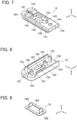
FIG. 7 is a perspective view showing a first insulator used in the connector assembly according to the embodiment. -
FIG. 8 is a perspective view showing a second insulator used in the connector assembly according to the embodiment when viewed from an obliquely lower position. -
FIG. 9 is a perspective view showing a contact force ensuring member used in the connector assembly according to the embodiment. -
FIG. 10 is a perspective view showing a sheet type conductive member used in the connector assembly according to the embodiment. -
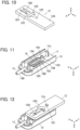
FIG. 11 is a perspective view showing a state where a second adhesive sheet, the contact force ensuring member, and a conductive portion of an electric wire are disposed on the second insulator. -
FIG. 12 is a perspective view showing a state where the sheet type conductive member is disposed on the second insulator. -
FIG. 13 is a perspective view showing a state where a first adhesive sheet is disposed on the sheet type conductive member. -
FIG. 14 is a cross-sectional view showing the state where the first adhesive sheet is disposed on the sheet type conductive member. -
FIG. 15 is a perspective view showing a state where the first insulator is disposed on the second insulator. -
FIG. 16 is a cross-sectional view showing the state where the first insulator is disposed on the second insulator. -
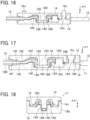
FIG. 17 is a cross-sectional view taken along line A-A inFIG. 2 . -
FIG. 18 is a cross-sectional view taken along line B-B inFIG. 3 . -
FIG. 19 is a perspective view showing a conventional connector. - An embodiment of the present invention is described below based on the accompanying drawings.
-
FIGS. 1 to 4 show a connector assembly according to the embodiment. The connector assembly is obtained by connecting a coatedelectric wire 13 to a sheet typeconductive member 12 by means of aconnector 11. - The sheet type
conductive member 12 has a top surface and a bottom surface facing in opposite directions from each other and has aflexible conductor 12A exposed at least on the top surface. As the sheet typeconductive member 12, conductive cloth woven using a conductive thread such as silver can be used, for example. When such conductive cloth is used, theflexible conductor 12A is exposed not only on the top surface but also on the bottom surface of the sheet typeconductive member 12. In addition, one obtained by applying a conductive ink on a surface of cloth having no conductivity by printing or another method to form theflexible conductor 12A on the surface thereof can also be used as the sheet typeconductive member 12. Further, a member obtained by forming theflexible conductor 12A formed of a conductive pattern on a surface of an insulating sheet body such as a resin film may be used as the sheet typeconductive member 12. - The sheet type
conductive member 12 has a band shape extending in a predetermined direction. - The coated
electric wire 13 has a structure in which an outer periphery of a conductor portion to be described later is covered with an insulation coating portion. With theconnector 11, the conductor portion of the coatedelectric wire 13 is electrically connected to theflexible conductor 12A of the sheet typeconductive member 12. - The coated
electric wire 13 extends in the same direction as the direction in which the sheet typeconductive member 12 of band shape extends. - For convenience, the predetermined direction in which the sheet type
conductive member 12 extends toward theconnector 11 is called "-Y direction," the width direction of the sheet typeconductive member 12 of band shape "X direction," and the direction orthogonal to an XY plane "Z direction." -
FIGS. 5 and6 show assembly views of the connector assembly. The connector assembly includes afirst insulator 14 and asecond insulator 15. - The sheet type
conductive member 12 is disposed on the +Z direction side of thefirst insulator 14 via a firstadhesive sheet 16, and aconductor portion 13A exposed from aninsulation coating portion 13B of the coatedelectric wire 13 is disposed on the +Z direction side of the sheet typeconductive member 12. Theconductor portion 13A of the coatedelectric wire 13 may be a so-called solid wire that is formed of one conductor or a so-called stranded wire that is formed by twisting a plurality of conductors. - Further, a contact
force ensuring member 18 is disposed on the +Z direction side of theconductor portion 13A of the coatedelectric wire 13 via a secondadhesive sheet 17, and thesecond insulator 15 is disposed on the +Z direction side of the contactforce ensuring member 18. - The
first insulator 14, the firstadhesive sheet 16, the secondadhesive sheet 17, the contactforce ensuring member 18, and thesecond insulator 15 constitute theconnector 11. - As shown in
FIG. 7 , thefirst insulator 14 includes aflat plate portion 14A of substantially rectangular shape extending along an XY plane, and a +Z directional surface of theflat plate portion 14A forms afirst retaining surface 14B of flat shape. Thefirst retaining surface 14B is provided at its center with a recessedportion 14C recessed in the -Z direction. Further, the recessedportion 14C is provided at its center with aprojection 14D of substantially prismatic shape projecting toward the +Z direction. Theprojection 14D projects higher than thefirst retaining surface 14B in the +Z direction. - In the
first retaining surface 14B, aninsertion groove 14E is formed to extend in the -Y direction from the recessedportion 14C, and at a -Y directional end portion of theinsertion groove 14E, aninsertion groove 14F is formed with a larger groove width than that of theinsertion groove 14E. - At a +Y directional end portion of the recessed
portion 14C, aninsertion hole 14G of recess shape is formed to communicate with the recessedportion 14C. - The
flat plate portion 14A includes three through-holes 14H separately formed on opposite sides of theinsertion groove 14E in the X direction and on the +Y direction side of theinsertion hole 14G, the through-holes 14H penetrating theflat plate portion 14A in the Z direction. - In addition,
step portions 14J extending in the Y direction are separately formed at X-directional opposite lateral surfaces of theflat plate portion 14A. - As shown in
FIG. 8 , thesecond insulator 15 includes aflat plate portion 15A of substantially rectangular shape extending along an XY plane, and a -Z directional surface of theflat plate portion 15A forms asecond retaining surface 15B of flat shape. Thesecond retaining surface 15B is provided at its center with aprotrusion portion 15C jutting in the -Z direction. Further, theprotrusion portion 15C is provided at its center with aprojection accommodating portion 15D of recess shape that is recessed in the +Z direction and is deeper than thesecond retaining surface 15B. - On the -Y directional side of the
projection accommodating portion 15D, aninsertion groove 15E is formed to extend in the -Y direction, and at a -Y directional end portion of theinsertion groove 15E, aninsertion groove 15F is formed with a larger groove width than that of theinsertion groove 15E. - On the +Y direction side of the
protrusion portion 15C, atip retaining portion 15G of columnar shape is formed to protrude in the -Z direction from thesecond retaining surface 15B, and aslit 15H is formed in thetip retaining portion 15G to extend in the Y direction so as to divide thetip retaining portion 15G in two in the X direction. Thetip retaining portion 15G is to retain a tip of theconductor portion 13A of the coatedelectric wire 13, and theslit 15H has a slit width slightly smaller than the diameter of theconductor portion 13A of the coatedelectric wire 13 and is configured such that theconductor portion 13A may be inserted thereinto. - The
flat plate portion 15A includes threebosses 15J separately formed on opposite sides of theinsertion groove 15E in the X direction and on the +Y direction side of thetip retaining portion 15G, thebosses 15J protruding in the -Z direction. - In addition, at the X-directional opposite lateral portions of the
flat plate portion 15A,lateral plates 15K are separately formed to protrude in the -Z direction and extend in the Y direction. - When the
first insulator 14 and thesecond insulator 15 are joined to each other, theinsertion groove 14E of thefirst insulator 14 and theinsertion groove 15E of thesecond insulator 15 work together to retain theconductor portion 13A of the coatedelectric wire 13, and theinsertion groove 14F of thefirst insulator 14 and theinsertion groove 15F of thesecond insulator 15 work together to retain theinsulation coating portion 13B of the coatedelectric wire 13 so as to constitute an insulation coat retaining portion. - The contact
force ensuring member 18 is to ensure a contact force between theconductor portion 13A of the coatedelectric wire 13 and theflexible conductor 12A of the sheet typeconductive member 12. As shown inFIG. 9 , the contactforce ensuring member 18 is formed of a metal sheet being bent and includes aprojection penetrating hole 18A which theprojection 14D of thefirst insulator 14 penetrates, and a pair ofpressing portions 18B facing each other in the Y direction across theprojection penetrating hole 18A and protruding in the +Z direction. - As shown in
FIG. 10 , the sheet typeconductive member 12 has an H-shapedopening portion 12B penetrating the sheet typeconductive member 12 in the Z direction, and a pair of projectingportions 12C are formed to project from Y directional opposite edges of theopening portion 12B toward the inside of theopening portion 12B and face each other in the Y direction. - Further, the sheet type
conductive member 12 is provided with through-holes tip retaining portion 15G and a +Ydirectional boss 15J of thesecond insulator 15 and penetrating the sheet typeconductive member 12 in the Z direction. - When the
connector 11 is assembled to produce the connector assembly, first, as shown inFIG. 11 , thesecond adhesive sheet 17 is disposed on thesecond retaining surface 15B of thesecond insulator 15. Thesecond adhesive sheet 17 has an opening portion corresponding to theprotrusion portion 15C and thetip retaining portion 15G of thesecond insulator 15 and three opening portions separately corresponding to the threebosses 15J. Thesecond adhesive sheet 17 is disposed on thesecond retaining surface 15B in the state where theprotrusion portion 15C, thetip retaining portion 15G, and the threebosses 15J penetrate through these opening portions. - In addition, the contact
force ensuring member 18 is disposed on theprotrusion portion 15C of thesecond insulator 15, and the pair ofpressing portions 18B of the contactforce ensuring member 18 are inserted into theprojection accommodating portion 15D of thesecond insulator 15 along Y directional inner lateral surfaces of theprojection accommodating portion 15D. - Further, the
conductor portion 13A exposed as a result of removal of a portion of theinsulation coating portion 13B at a +Y directional end portion of the coatedelectric wire 13 is disposed on the contactforce ensuring member 18, and the tip of theconductor portion 13A is press-fitted in theslit 15H formed in thetip retaining portion 15G of thesecond insulator 15, thereby being temporarily retained in thetip retaining portion 15G. - Next, as shown in
FIG. 12 , the sheet typeconductive member 12 is disposed on thesecond insulator 15 while the +Ydirectional boss 15J of thesecond insulator 15 penetrates the through-hole 12E of the sheet typeconductive member 12. - Further, as shown in
FIG. 13 , thefirst adhesive sheet 16 is disposed on the sheet typeconductive member 12. Thefirst adhesive sheet 16 has an opening portion corresponding to theopening portion 12B and the through-hole 12D of the sheet typeconductive member 12 and three opening portions separately corresponding to the threebosses 15J of thesecond insulator 15. Thefirst adhesive sheet 16 is disposed on the sheet typeconductive member 12 in the state where the threebosses 15J penetrate the corresponding opening portions. - At this time, as shown in
FIG. 14 , theconductor portion 13A of the coatedelectric wire 13 extends in the Y direction above theprojection accommodating portion 15D of thesecond insulator 15, and the +Y directional tip of theconductor portion 13A is press-fitted in theslit 15H of thetip retaining portion 15G of thesecond insulator 15. Further, the H-shapedopening portion 12B of the sheet typeconductive member 12 is situated on theconductor portion 13A extending in the Y direction above theprojection accommodating portion 15D of thesecond insulator 15. Theopening portion 12B of the sheet typeconductive member 12 is exposed toward the -Z direction through the corresponding opening portion of thefirst adhesive sheet 16. - In this state, the
first insulator 14 is pressed toward thesecond insulator 15 relatively in the +Z direction, whereby thefirst insulator 14 is disposed on thesecond insulator 15 while the threebosses 15J of thesecond insulator 15 separately penetrate the three through-holes 14H of thefirst insulator 14 as shown inFIG. 15 . Consequently, the sheet typeconductive member 12 and theconductor portion 13A of the coatedelectric wire 13 are sandwiched between thefirst retaining surface 14B of thefirst insulator 14 and thesecond retaining surface 15B of thesecond insulator 15. - At this time, as shown in
FIG. 16 , theprojection 14D formed to project in the recessedportion 14C of thefirst insulator 14 is inserted into the H-shapedopening portion 12B of the sheet typeconductive member 12, and is accommodated in theprojection accommodating portion 15D of thesecond insulator 15 while a +Z directional end portion of theprojection 14D pushes the pair of projectingportions 12C of the sheet typeconductive member 12 and theconductor portion 13A of the coatedelectric wire 13. - The three
bosses 15J of thesecond insulator 15 penetrate the three through-holes 14H of thefirst insulator 14 and project on the -Z direction side from thefirst insulator 14. - When a heat treatment is performed to melt the
first adhesive sheet 16 and thesecond adhesive sheet 17 while thefirst insulator 14 is kept to be pressed against thesecond insulator 15, thefirst insulator 14 and thesecond insulator 15 are adhered to each other directly or via the sheet typeconductive member 12, and a portion between thefirst insulator 14 and thesecond insulator 15 is sealed. Further, tips of the threebosses 15J projecting on the -Z direction side of thefirst insulator 14 are thermally deformed, whereby thefirst insulator 14 and thesecond insulator 15 are fixed to each other. Thus, the assembling operation of theconnector 11 is completed. -
FIG. 17 shows the thus-produced connector assembly. While theprojection 14D of thefirst insulator 14 is accommodated in theprojection accommodating portion 15D of thesecond insulator 15 with the +Z directional end portion of theprojection 14D pushing the pair of projectingportions 12C of the sheet typeconductive member 12 and theconductor portion 13A of the coatedelectric wire 13, the pair ofpressing portions 18B of the contactforce ensuring member 18 are inserted in theprojection accommodating portion 15D. Therefore, each projectingportion 12C of the sheet typeconductive member 12 deforms to conform to a surface of theprojection 14D, and theconductor portion 13A of the coatedelectric wire 13 is held between a surface of the projectingportion 12C of the sheet typeconductive member 12 and the correspondingpressing portion 18B of the contactforce ensuring member 18 to be bent to conform to the surface of the deformed projectingportion 12C of the sheet typeconductive member 12. - Since the
projection 14D has a substantially prismatic shape, each projectingportion 12C, deformed to conform to the surface of theprojection 14D, of the sheet typeconductive member 12 and theconductor portion 13A of the coatedelectric wire 13 are held between the correspondingpressing portion 18B of the contactforce ensuring member 18 extending along a Y directional inner lateral surface of theprojection accommodating portion 15D and a Y directional outer lateral surface of theprojection 14D, and theconductor portion 13A of the coatedelectric wire 13 contacts theflexible conductor 12A exposed on the surface of the projectingportion 12C of the sheet typeconductive member 12 with a predetermined contact force and is electrically connected to theflexible conductor 12A. - In a -Y directional portion of the
connector 11, theconductor portion 13A of the coatedelectric wire 13 is retained in theinsertion groove 14E of thefirst insulator 14 and theinsertion groove 15E of thesecond insulator 15, while theinsulation coating portion 13B of the coatedelectric wire 13 is retained in theinsertion groove 14F of thefirst insulator 14 and theinsertion groove 15F of thesecond insulator 15. - In addition, the
conductor portion 13A of the coatedelectric wire 13 is bent to conform to the surface of the deformed projectingportions 12C of the sheet typeconductive member 12, whereby the tip of theconductor portion 13 A temporarily retained in theslit 15H of thetip retaining portion 15G of thesecond insulator 15 is pulled out from theslit 15H. - Further, as shown in
FIG. 18 , the pair oflateral plates 15K of thesecond insulator 15 are fitted in the pair ofstep portions 14J of thefirst insulator 14. - Thus, with the
connector 11 according to the embodiment, theprojection 14D of thefirst insulator 14 is inserted in the inside of the contactforce ensuring member 18 that is inserted in theprojection accommodating portion 15D of thesecond insulator 15 while pushing the sheet typeconductive member 12 and theconductor portion 13A of the coatedelectric wire 13, whereby theflexible conductor 12A exposed on the top surface of the sheet typeconductive member 12 is electrically connected to theconductor portion 13A of the coatedelectric wire 13. Hence, the connector can reduce the size thereof while improving reliability of the electric connection between theflexible conductor 12A and theconductor portion 13A. - In particular, since the
projection 14D of thefirst insulator 14 is inserted in theopening portion 12B of the sheet typeconductive member 12, and each projectingportion 12C of the sheet typeconductive member 12 contacts theconductor portion 13A of the coatedelectric wire 13 between the inner lateral surface of theprojection accommodating portion 15D of thesecond insulator 15 and the outer lateral surface of theprojection 14D, only theconductor portion 13A of the coatedelectric wire 13 is disposed between a +Z directional top portion of theprojection 14D and a bottom portion of theprojection accommodating portion 15D, with the sheet typeconductive member 12 being not present therebetween. Further, while the pair ofpressing portions 18B of the contactforce ensuring member 18 are inserted in theprojection accommodating portion 15D, thesepressing portions 18B do not extend between the +Z directional top portion of theprojection 14D and the bottom portion of theprojection accommodating portion 15D. Therefore, theconnector 11 can be reduced in thickness. - In addition, the
first insulator 14 includes the recessedportion 14C formed in thefirst retaining surface 14B and theprojection 14D formed in the recessedportion 14C to project higher than thefirst retaining surface 14B in the +Z direction, and thesecond insulator 15 includes theprotrusion portion 15C formed on thesecond retaining surface 15B and theprojection accommodating portion 15D of recess shape formed in theprotrusion portion 15C to be deeper than thesecond retaining surface 15B. Therefore, thefirst insulator 14 other than theprojection 14D is not entirely thinned, but a part of thefirst insulator 14 within the region where the recessedportion 14C is formed, other than theprojection 14D, is thinned, and further, the part of thesecond insulator 15 where theprojection accommodating portion 15D is formed is thinned, whereby thethin connector 11 can be achieved. - Thus, by limiting parts required to be thinned in the
first insulator 14 and thesecond insulator 15, thefirst insulator 14 and thesecond insulator 15 can be molded with an insulating resin without impairing fluidity of a melted resin in a mold. - In addition, by limiting parts required to be thinned, the intensity of the
first insulator 14 and thesecond insulator 15 can be ensured, and even when an external force is applied to theconnector 11 via the coatedelectric wire 13 or the sheet typeconductive member 12, the occurrence of breakage or the like can be avoided. - In addition, since the
first adhesive sheet 16 and thesecond adhesive sheet 17 are used to seal between thefirst insulator 14 and thesecond insulator 15, it is possible to prevent entry of water into a site of electric connection between theflexible conductor 12A of the sheet typeconductive member 12 and theconductor portion 13A of the coatedelectric wire 13. - When the
connector 11 of the embodiment is applied to smart clothes, and an electrode (not shown) is connected to theflexible conductor 12A of the sheet typeconductive member 12, the electrode disposed at a measurement position and a wearable device can be connected to each other by means of the inexpensive coatedelectric wire 13 with low electric resistance. - While in the embodiment described above, the
tip retaining portion 15G for retaining the tip of theconductor portion 13A of the coatedelectric wire 13 is formed in thesecond insulator 15, the tip retaining portion may be formed in thefirst insulator 14. - In addition, while the three
bosses 15J of thesecond insulator 15 penetrate the three through-holes 14H of thefirst insulator 14 in the embodiment described above, it is possible to configure the connector such that, conversely, a plurality of bosses formed in thefirst insulator 14 penetrate a plurality of through-holes formed in thesecond insulator 15. - In the embodiment described above, the pair of
pressing portions 18B of the contactforce ensuring member 18 is inserted in theprojection accommodating portion 15D of thesecond insulator 15, and each projectingportion 12C of the sheet typeconductive member 12 and theconductor portion 13A of the coatedelectric wire 13 are held between the outer lateral surface of theprojection 14D and the correspondingpressing portion 18B of the contactforce ensuring member 18, but the invention is not limited thereto. - Even when it is configured such that each projecting
portion 12C of the sheet typeconductive member 12 and theconductor portion 13A of the coatedelectric wire 13 are directly held between the outer lateral surface of theprojection 14D and the inner lateral surface of theprojection accommodating portion 15D without using the contactforce ensuring member 18, theconductor portion 13A of the coatedelectric wire 13 can be brought into contact with and electrically connected to theflexible conductor 12A exposed on the top surface of the projectingportion 12C of the sheet typeconductive member 12. However, the contactforce ensuring member 18 is preferably used because a contact force between theconductor portion 13A of the coatedelectric wire 13 and theflexible conductor 12A of the sheet typeconductive member 12 is reliably ensured. - While the coated
electric wire 13 is used as an electric wire to be connected to the sheet typeconductive member 12 in the embodiment described above, an electric wire formed of only theconductor portion 13A whose outer periphery is not covered with theinsulation coating portion 13B made of an insulating material may also be connected to the sheet typeconductive member 12. - Further, in the embodiment described above, one
projection 14D formed in thefirst insulator 14 is accommodated in oneprojection accommodating portion 15D formed in thesecond insulator 15 to thereby connect theconductor portion 13A of one coatedelectric wire 13 to theflexible conductor 12A of one sheet typeconductive member 12, but the connector can be configured such that, using the first insulator having a plurality of projections and the second insulator having a plurality of projection accommodating portions, conductor portions of a plurality of electric wires are connected to flexible conductors of a plurality of sheet type conductive members in a similar manner.
Claims (11)
- A connector (11) configured to connect a conductor portion (13A) of an electric wire (13) to a flexible conductor (12A) exposed on at least one surface of a sheet type conductive member (12) having an opening portion (12B), the connector comprising:a first insulator (14) including a first retaining surface (14B), a recessed portion (14C) formed in the first retaining surface, and a projection (14D) formed in the recessed portion to project higher than the first retaining surface; anda second insulator (15) including a second retaining surface (15B) that faces the first retaining surface, a protrusion portion (15C) that is formed on the second retaining surface and faces the recessed portion, and a projection accommodating portion (15D) of recess shape that is formed in the protrusion portion and is deeper than the second retaining surface,wherein the first insulator (14) and the second insulator (15) are joined to each other such that the projection is inserted in the opening portion of the sheet type conductive member, that the sheet type conductive member and the electric wire are held between the first retaining surface and the second retaining surface, and that the sheet type conductive member and the electric wire are disposed to overlap each other between the recessed portion and the protrusion portion, andat least part of the projection is accommodated in the projection accommodating portion, whereby the conductor portion (13A) of the electric wire (13) is electrically connected to the flexible conductor (12A) of the sheet type conductive member (12) between an outer lateral surface of the projection and an inner lateral surface of the projection accommodating portion.
- The connector according to claim 1,wherein the sheet type conductive member (12) extends in a predetermined direction from the first insulator and the second insulator along the first retaining surface and the second retaining surface, andthe electric wire (13) extends in an opposite direction of the predetermined direction from the first insulator and the second insulator along the first retaining surface and the second retaining surface.
- The connector according to claim 1 or 2, wherein the first insulator (14) and the second insulator (15) are adhered to each other directly or via the sheet type conductive member (12).
- The connector according to any one of claims 1-3, further comprising a contact force ensuring member (18) for ensuring a contact force between the conductor portion and the flexible conductor, the contact force ensuring member being disposed on an outside of the conductor portion and the flexible conductor that are in contact with each other in the projection accommodating portion.
- The connector according to claim 4, wherein the contact force ensuring member (18) is formed of a bent metal sheet and includes a projection penetrating hole (18A) which the projection of the first insulator penetrates, and a pair of pressing portions (18B) that face each other across the projection penetrating hole.
- The connector according to any one of claims 1-5, wherein one of the first insulator (14) and the second insulator (15) includes a tip retaining portion (15G) for retaining a tip of the conductor portion of the electric wire.
- The connector according to claim 6, wherein the tip retaining portion (15G) includes a slit (15H) in which the tip of the conductor portion is inserted.
- The connector according to any one of claims 1-7,wherein the electric wire (13) includes an insulation coating portion (13B) which covers an outer periphery of the conductor portion, andthe first insulator (14) and the second insulator (15) have insulation coat retaining portions (14F, 15F) for retaining the insulation coating portion of the electric wire.
- The connector according to any one of claims 1-8,wherein one of the first insulator (14) and the second insulator (15) includes a boss (15J),another one of the first insulator and the second insulator includes a boss through-hole (14H) which the boss penetrates, anda head of the boss having penetrated the boss through-hole is thermally deformed.
- A connector assembly comprising:the connector (11) according to any one of claims 1-9;the sheet type conductive member (12); andthe electric wire (13),wherein the conductor portion (13A) of the electric wire (13) is electrically connected to the flexible conductor (12A) of the sheet type conductive member (12) by using the connector (11).
- The connector assembly according to claim 10,wherein the sheet type conductive member (12) includes the opening portion (12B) of H-shape, and a pair of projecting portions (12C) projecting from edge portions of the opening portion facing each other toward an inside of the opening portion, the flexible conductor being exposed on the pair of projecting portions, andthe conductor portion (13A) of the electric wire is electrically connected to the flexible conductor (12A) on the pair of projecting portions between an inner lateral surface of the projection accommodating portion (15D) and an outer lateral surface of the projection (14D) of the connector.
Applications Claiming Priority (1)
| Application Number | Priority Date | Filing Date | Title |
|---|---|---|---|
| JP2023097412A JP2024178974A (en) | 2023-06-14 | 2023-06-14 | Connector and connector assembly |
Publications (2)
| Publication Number | Publication Date |
|---|---|
| EP4478554A1 true EP4478554A1 (en) | 2024-12-18 |
| EP4478554B1 EP4478554B1 (en) | 2025-05-14 |
Family
ID=91129032
Family Applications (1)
| Application Number | Title | Priority Date | Filing Date |
|---|---|---|---|
| EP24173989.5A Active EP4478554B1 (en) | 2023-06-14 | 2024-05-03 | Connector and connector assembly |
Country Status (4)
| Country | Link |
|---|---|
| US (1) | US20240421504A1 (en) |
| EP (1) | EP4478554B1 (en) |
| JP (1) | JP2024178974A (en) |
| CN (1) | CN119153999A (en) |
Citations (6)
| Publication number | Priority date | Publication date | Assignee | Title |
|---|---|---|---|---|
| JPS52147261U (en) * | 1976-05-01 | 1977-11-08 | ||
| WO2004109862A1 (en) * | 2003-05-30 | 2004-12-16 | 3M Innovative Properties Company | Wire connection structure and connector |
| JP2007214087A (en) | 2006-02-13 | 2007-08-23 | Fujikura Ltd | connector |
| JP2008270006A (en) * | 2007-04-23 | 2008-11-06 | Yazaki Corp | Flat cable connection method |
| EP3800739A1 (en) * | 2019-10-03 | 2021-04-07 | Japan Aviation Electronics Industry, Ltd. | Connector and connecting method |
| EP4120480A1 (en) * | 2021-07-14 | 2023-01-18 | Japan Aviation Electronics Industry, Ltd. | Connector and connector assembly |
Family Cites Families (18)
| Publication number | Priority date | Publication date | Assignee | Title |
|---|---|---|---|---|
| JP2543150Y2 (en) * | 1991-03-29 | 1997-08-06 | 古河電気工業株式会社 | Flat cable connection structure |
| KR100360934B1 (en) * | 1994-07-29 | 2003-01-24 | 닛산 지도우샤 가부시키가이샤 | Flat cable with conductor ends accessible to connectors |
| JP2606177B2 (en) * | 1995-04-26 | 1997-04-30 | 日本電気株式会社 | Printed wiring board |
| US6007371A (en) * | 1998-05-20 | 1999-12-28 | General Motors Corporation | Fold flex electrical connector |
| DE50102448D1 (en) * | 2000-01-31 | 2004-07-08 | Hirschmann Austria Gmbh Rankwe | crimp contact |
| DE10048693A1 (en) * | 2000-09-30 | 2002-05-08 | Kostal Leopold Gmbh & Co Kg | Method for equipping an object with a cable harness formed at least from a flat conductor and electrical / electronic devices connected to it, use of such a method and assembly system |
| US6602092B2 (en) * | 2001-08-20 | 2003-08-05 | Ludlow Company Lp | Cable assembly module with compressive connector |
| US6520810B1 (en) * | 2001-10-24 | 2003-02-18 | Molex Incorporated | Connector system for interconnection with flat flexible circuitry |
| US20040094328A1 (en) * | 2002-11-16 | 2004-05-20 | Fjelstad Joseph C. | Cabled signaling system and components thereof |
| US7104834B2 (en) * | 2003-02-20 | 2006-09-12 | Sherwood Services Ag | System and method for connecting an electrosurgical instrument to a generator |
| JP2007305516A (en) * | 2006-05-15 | 2007-11-22 | Fujitsu Ltd | Coaxial connector, connector assembly, printed circuit board, and electronic device |
| US8342459B2 (en) * | 2008-03-06 | 2013-01-01 | Covidien Lp | Wire organizer |
| TWM421617U (en) * | 2011-06-09 | 2012-01-21 | Bing Xu Prec Co Ltd | Cable connector |
| KR102060977B1 (en) * | 2015-09-02 | 2019-12-31 | 후루카와 덴키 고교 가부시키가이샤 | Waterproof connection structure, connection structure and partition member |
| DE102017208625B3 (en) * | 2017-05-22 | 2018-11-15 | Albert-Ludwigs-Universität Freiburg | CONNECTOR ELEMENTS, SOCKET ELEMENT AND IMPLANTABLE ELECTRICAL CONNECTOR AND MANUFACTURING METHOD |
| DE102021212194A1 (en) * | 2021-10-28 | 2023-05-04 | Robert Bosch Gesellschaft mit beschränkter Haftung | Connector, contacting arrangement with a connector and method for connecting a connector to a cable |
| US12347983B2 (en) * | 2022-11-30 | 2025-07-01 | Lear Corporation | Connector for an electrical terminal with a crimped spring |
| US12249818B2 (en) * | 2023-02-28 | 2025-03-11 | Lear Corporation | Electrical assembly |
-
2023
- 2023-06-14 JP JP2023097412A patent/JP2024178974A/en active Pending
-
2024
- 2024-04-02 CN CN202410396545.2A patent/CN119153999A/en active Pending
- 2024-04-15 US US18/635,517 patent/US20240421504A1/en active Pending
- 2024-05-03 EP EP24173989.5A patent/EP4478554B1/en active Active
Patent Citations (6)
| Publication number | Priority date | Publication date | Assignee | Title |
|---|---|---|---|---|
| JPS52147261U (en) * | 1976-05-01 | 1977-11-08 | ||
| WO2004109862A1 (en) * | 2003-05-30 | 2004-12-16 | 3M Innovative Properties Company | Wire connection structure and connector |
| JP2007214087A (en) | 2006-02-13 | 2007-08-23 | Fujikura Ltd | connector |
| JP2008270006A (en) * | 2007-04-23 | 2008-11-06 | Yazaki Corp | Flat cable connection method |
| EP3800739A1 (en) * | 2019-10-03 | 2021-04-07 | Japan Aviation Electronics Industry, Ltd. | Connector and connecting method |
| EP4120480A1 (en) * | 2021-07-14 | 2023-01-18 | Japan Aviation Electronics Industry, Ltd. | Connector and connector assembly |
Also Published As
| Publication number | Publication date |
|---|---|
| CN119153999A (en) | 2024-12-17 |
| JP2024178974A (en) | 2024-12-26 |
| EP4478554B1 (en) | 2025-05-14 |
| US20240421504A1 (en) | 2024-12-19 |
Similar Documents
| Publication | Publication Date | Title |
|---|---|---|
| EP3361575B1 (en) | Connector | |
| EP3376601B1 (en) | Connector | |
| EP4000436B1 (en) | Connector | |
| EP4340135B1 (en) | Connector | |
| EP3696918B1 (en) | Connecting method, connecting structure and connection terminal | |
| JP4084292B2 (en) | Pressure welding structure of coaxial cable | |
| US12230907B2 (en) | Electrical connector for connecting an electric wire to a flat flexible conductor and an electrical connector assembly therefor | |
| EP4478554B1 (en) | Connector and connector assembly | |
| US20240088590A1 (en) | Connector | |
| US10862254B2 (en) | Coated conductive wire connecting method, coated conductive wire connecting structure and coated conductive wire connecting member | |
| EP4462605B1 (en) | Connector | |
| EP4379964A1 (en) | Connector assembly and connecting method | |
| EP4343974A1 (en) | Connector | |
| EP4346013A1 (en) | Connector, connector assembly, and connecting method | |
| US20240145955A1 (en) | Connector and connector assembly | |
| EP4387004A1 (en) | Connector |
Legal Events
| Date | Code | Title | Description |
|---|---|---|---|
| PUAI | Public reference made under article 153(3) epc to a published international application that has entered the european phase |
Free format text: ORIGINAL CODE: 0009012 |
|
| STAA | Information on the status of an ep patent application or granted ep patent |
Free format text: STATUS: REQUEST FOR EXAMINATION WAS MADE |
|
| 17P | Request for examination filed |
Effective date: 20240503 |
|
| AK | Designated contracting states |
Kind code of ref document: A1 Designated state(s): AL AT BE BG CH CY CZ DE DK EE ES FI FR GB GR HR HU IE IS IT LI LT LU LV MC ME MK MT NL NO PL PT RO RS SE SI SK SM TR |
|
| GRAP | Despatch of communication of intention to grant a patent |
Free format text: ORIGINAL CODE: EPIDOSNIGR1 |
|
| STAA | Information on the status of an ep patent application or granted ep patent |
Free format text: STATUS: GRANT OF PATENT IS INTENDED |
|
| RIC1 | Information provided on ipc code assigned before grant |
Ipc: H01R 4/06 20060101ALI20250224BHEP Ipc: H01R 12/59 20110101ALI20250224BHEP Ipc: H01R 12/63 20110101AFI20250224BHEP |
|
| GRAS | Grant fee paid |
Free format text: ORIGINAL CODE: EPIDOSNIGR3 |
|
| INTG | Intention to grant announced |
Effective date: 20250311 |
|
| GRAA | (expected) grant |
Free format text: ORIGINAL CODE: 0009210 |
|
| STAA | Information on the status of an ep patent application or granted ep patent |
Free format text: STATUS: THE PATENT HAS BEEN GRANTED |
|
| AK | Designated contracting states |
Kind code of ref document: B1 Designated state(s): AL AT BE BG CH CY CZ DE DK EE ES FI FR GB GR HR HU IE IS IT LI LT LU LV MC ME MK MT NL NO PL PT RO RS SE SI SK SM TR |
|
| REG | Reference to a national code |
Ref country code: GB Ref legal event code: FG4D |
|
| REG | Reference to a national code |
Ref country code: CH Ref legal event code: EP |
|
| REG | Reference to a national code |
Ref country code: IE Ref legal event code: FG4D |
|
| REG | Reference to a national code |
Ref country code: DE Ref legal event code: R096 Ref document number: 602024000129 Country of ref document: DE |
|
| REG | Reference to a national code |
Ref country code: NL Ref legal event code: MP Effective date: 20250514 |
|
| PG25 | Lapsed in a contracting state [announced via postgrant information from national office to epo] |
Ref country code: FI Free format text: LAPSE BECAUSE OF FAILURE TO SUBMIT A TRANSLATION OF THE DESCRIPTION OR TO PAY THE FEE WITHIN THE PRESCRIBED TIME-LIMIT Effective date: 20250514 Ref country code: PT Free format text: LAPSE BECAUSE OF FAILURE TO SUBMIT A TRANSLATION OF THE DESCRIPTION OR TO PAY THE FEE WITHIN THE PRESCRIBED TIME-LIMIT Effective date: 20250915 Ref country code: ES Free format text: LAPSE BECAUSE OF FAILURE TO SUBMIT A TRANSLATION OF THE DESCRIPTION OR TO PAY THE FEE WITHIN THE PRESCRIBED TIME-LIMIT Effective date: 20250514 |
|
| REG | Reference to a national code |
Ref country code: LT Ref legal event code: MG9D |
|
| PG25 | Lapsed in a contracting state [announced via postgrant information from national office to epo] |
Ref country code: NO Free format text: LAPSE BECAUSE OF FAILURE TO SUBMIT A TRANSLATION OF THE DESCRIPTION OR TO PAY THE FEE WITHIN THE PRESCRIBED TIME-LIMIT Effective date: 20250814 Ref country code: GR Free format text: LAPSE BECAUSE OF FAILURE TO SUBMIT A TRANSLATION OF THE DESCRIPTION OR TO PAY THE FEE WITHIN THE PRESCRIBED TIME-LIMIT Effective date: 20250815 |
|
| PG25 | Lapsed in a contracting state [announced via postgrant information from national office to epo] |
Ref country code: PL Free format text: LAPSE BECAUSE OF FAILURE TO SUBMIT A TRANSLATION OF THE DESCRIPTION OR TO PAY THE FEE WITHIN THE PRESCRIBED TIME-LIMIT Effective date: 20250514 Ref country code: NL Free format text: LAPSE BECAUSE OF FAILURE TO SUBMIT A TRANSLATION OF THE DESCRIPTION OR TO PAY THE FEE WITHIN THE PRESCRIBED TIME-LIMIT Effective date: 20250514 |
|
| REG | Reference to a national code |
Ref country code: AT Ref legal event code: MK05 Ref document number: 1795640 Country of ref document: AT Kind code of ref document: T Effective date: 20250514 |
|
| PG25 | Lapsed in a contracting state [announced via postgrant information from national office to epo] |
Ref country code: BG Free format text: LAPSE BECAUSE OF FAILURE TO SUBMIT A TRANSLATION OF THE DESCRIPTION OR TO PAY THE FEE WITHIN THE PRESCRIBED TIME-LIMIT Effective date: 20250514 |
|
| PG25 | Lapsed in a contracting state [announced via postgrant information from national office to epo] |
Ref country code: HR Free format text: LAPSE BECAUSE OF FAILURE TO SUBMIT A TRANSLATION OF THE DESCRIPTION OR TO PAY THE FEE WITHIN THE PRESCRIBED TIME-LIMIT Effective date: 20250514 |
|
| PG25 | Lapsed in a contracting state [announced via postgrant information from national office to epo] |
Ref country code: AT Free format text: LAPSE BECAUSE OF FAILURE TO SUBMIT A TRANSLATION OF THE DESCRIPTION OR TO PAY THE FEE WITHIN THE PRESCRIBED TIME-LIMIT Effective date: 20250514 |
|
| PG25 | Lapsed in a contracting state [announced via postgrant information from national office to epo] |
Ref country code: RS Free format text: LAPSE BECAUSE OF FAILURE TO SUBMIT A TRANSLATION OF THE DESCRIPTION OR TO PAY THE FEE WITHIN THE PRESCRIBED TIME-LIMIT Effective date: 20250814 |
|
| PG25 | Lapsed in a contracting state [announced via postgrant information from national office to epo] |
Ref country code: IS Free format text: LAPSE BECAUSE OF FAILURE TO SUBMIT A TRANSLATION OF THE DESCRIPTION OR TO PAY THE FEE WITHIN THE PRESCRIBED TIME-LIMIT Effective date: 20250914 |
|
| PG25 | Lapsed in a contracting state [announced via postgrant information from national office to epo] |
Ref country code: LV Free format text: LAPSE BECAUSE OF FAILURE TO SUBMIT A TRANSLATION OF THE DESCRIPTION OR TO PAY THE FEE WITHIN THE PRESCRIBED TIME-LIMIT Effective date: 20250514 |
|
| PG25 | Lapsed in a contracting state [announced via postgrant information from national office to epo] |
Ref country code: DK Free format text: LAPSE BECAUSE OF FAILURE TO SUBMIT A TRANSLATION OF THE DESCRIPTION OR TO PAY THE FEE WITHIN THE PRESCRIBED TIME-LIMIT Effective date: 20250514 Ref country code: SM Free format text: LAPSE BECAUSE OF FAILURE TO SUBMIT A TRANSLATION OF THE DESCRIPTION OR TO PAY THE FEE WITHIN THE PRESCRIBED TIME-LIMIT Effective date: 20250514 |
|
| PG25 | Lapsed in a contracting state [announced via postgrant information from national office to epo] |
Ref country code: CZ Free format text: LAPSE BECAUSE OF FAILURE TO SUBMIT A TRANSLATION OF THE DESCRIPTION OR TO PAY THE FEE WITHIN THE PRESCRIBED TIME-LIMIT Effective date: 20250514 |
|
| PG25 | Lapsed in a contracting state [announced via postgrant information from national office to epo] |
Ref country code: EE Free format text: LAPSE BECAUSE OF FAILURE TO SUBMIT A TRANSLATION OF THE DESCRIPTION OR TO PAY THE FEE WITHIN THE PRESCRIBED TIME-LIMIT Effective date: 20250514 |
|
| PG25 | Lapsed in a contracting state [announced via postgrant information from national office to epo] |
Ref country code: SK Free format text: LAPSE BECAUSE OF FAILURE TO SUBMIT A TRANSLATION OF THE DESCRIPTION OR TO PAY THE FEE WITHIN THE PRESCRIBED TIME-LIMIT Effective date: 20250514 |
|
| PG25 | Lapsed in a contracting state [announced via postgrant information from national office to epo] |
Ref country code: IT Free format text: LAPSE BECAUSE OF FAILURE TO SUBMIT A TRANSLATION OF THE DESCRIPTION OR TO PAY THE FEE WITHIN THE PRESCRIBED TIME-LIMIT Effective date: 20250514 |
|
| REG | Reference to a national code |
Ref country code: DE Ref legal event code: R097 Ref document number: 602024000129 Country of ref document: DE |
|
| PLBE | No opposition filed within time limit |
Free format text: ORIGINAL CODE: 0009261 |
|
| STAA | Information on the status of an ep patent application or granted ep patent |
Free format text: STATUS: NO OPPOSITION FILED WITHIN TIME LIMIT |
|
| REG | Reference to a national code |
Ref country code: CH Ref legal event code: L10 Free format text: ST27 STATUS EVENT CODE: U-0-0-L10-L00 (AS PROVIDED BY THE NATIONAL OFFICE) Effective date: 20260325 |
|
| 26N | No opposition filed |
Effective date: 20260217 |
|
| PG25 | Lapsed in a contracting state [announced via postgrant information from national office to epo] |
Ref country code: LT Free format text: LAPSE BECAUSE OF FAILURE TO SUBMIT A TRANSLATION OF THE DESCRIPTION OR TO PAY THE FEE WITHIN THE PRESCRIBED TIME-LIMIT Effective date: 20250514 |
|
| PGFP | Annual fee paid to national office [announced via postgrant information from national office to epo] |
Ref country code: DE Payment date: 20260402 Year of fee payment: 3 |
|
| PGFP | Annual fee paid to national office [announced via postgrant information from national office to epo] |
Ref country code: FR Payment date: 20260401 Year of fee payment: 3 |
|
| PG25 | Lapsed in a contracting state [announced via postgrant information from national office to epo] |
Ref country code: SE Free format text: LAPSE BECAUSE OF FAILURE TO SUBMIT A TRANSLATION OF THE DESCRIPTION OR TO PAY THE FEE WITHIN THE PRESCRIBED TIME-LIMIT Effective date: 20250514 |