Field
-
The present invention relates to surge protective devices (SPDs) for electrical power transmission lines.
Background
-
Frequently, excessive voltage or current is applied across service lines that deliver power to residences and commercial and institutional facilities. Such excess voltage or current spikes (transient overvoltages and surge currents) may result from lightning strikes, for example. The above events may be of particular concern in telecommunications distribution centers, hospitals and other facilities where equipment damage caused by overvoltages and/or current surges is not acceptable and resulting down time may be very costly.
-
Typically, sensitive electronic equipment may be protected against transient overvoltages and surge currents using surge protective devices (SPDs). For example, an overvoltage protection device may be installed at a power input of equipment to be protected, which is typically protected against overcurrents when it fails. Typical failure mode of an SPD is a short circuit. The overcurrent protection typically employed is a combination of an internal thermal disconnector to protect the device from overheating due to increased leakage currents and an external fuse to protect the device from higher fault currents. Different SPD technologies may avoid the use of the internal thermal disconnector because, in the event of failure, they change their operation mode to a low ohmic resistance.
-
In the event of a surge current in a line L (e.g., a voltage line of a three phase electrical power circuit), protection of power system load devices may necessitate providing a current path to ground for the excess current of the surge current. The surge current may generate a transient overvoltage between the line L and the neutral line N (the neutral line N may be conductively coupled to an earth ground PE). Since the transient overvoltage significantly exceeds the operating voltage of the SPD, the SPD will become conductive, allowing the excess current to flow from line L through SPD to the neutral N. Once the surge current has been conducted to neutral N, the overvoltage condition ends and the SPD may become non-conducting again. However, in some cases, one or more SPDs may begin to allow a leakage current to be conducted even at voltages that are lower that the operating voltage of the SPDs. Such conditions may occur in the case of an SPD deteriorating.
-
Terminal blocks are commonly used to terminate and connect an electrical cable to a circuit or other electrical system via a busbar system.
Summary
-
According to some embodiments, a surge protective device (SPD) system for use with an input cable and an output cable of an electrical power supply transmission system includes a base module and an SPD module. The base module is configured as a feed-through terminal block. The base module includes a feed-through circuit including: an input connector configured to connect the input cable; and an output connector configured to connect the output cable and electrically connected to the input connector. The SPD module is configured to be removably mounted on the base module. The SPD module includes an SPD circuit including an overvoltage protection component. The SPD system is configured to be used in each of: a protected mode, wherein the SPD module is mounted on the base module and provides overvoltage protection to the feed-through circuit; and an unprotected mode, wherein the SPD module is not mounted on the base module and the base module operates as a feed-through terminal block without overvoltage protection from the SPD module. The SPD module is a Type 1 or Type 2 Surge Protective Device according to International Electrotechnical Commission (IEC) standard 61643-11:2011 (dated 9 March 2011).
-
According to some embodiments, the base module is a feed-through terminal block rated according to IEC 60947-1-7:2009 to sustain at least 80 Amps as a continuous load current.
-
In some embodiments, the SPD module is rated according to IEC 61643-11:2011 for at least 20kA nominal discharge current (In).
-
In some embodiments, the input connector and the output connector are each configured to accept or receive and electrically connect electrical power transmission cables having a cross-sectional area of 2 mm2 or greater.
-
According to some embodiments, the overvoltage protection component is a varistor.
-
In some embodiments, the SPD module includes a thermal disconnect mechanism configured to disconnect the varistor in response to overheating of the SPD module.
-
In some embodiments, the SPD module includes an indicator system configured to provide an alert in response to actuation of the thermal disconnect mechanism.
-
In some embodiments, the indicator system includes a remote indicator system including a switch, and a remote monitoring connector forming a part of the SPD module.
-
According to some embodiments, the feed-through circuit includes a conductor member electrically connecting the output connector to the input connector, and the SPD module includes a connector that directly contacts the conductor member to connect the overvoltage protection component to the feed-through circuit.
-
According to some embodiments, a first portion of the conductor member forms a part of the input connector, and a second portion of the conductor member forms a part of the output connector.
-
In some embodiments, the input connector and the output connector are spring clamp connectors, and the input connector and the output connector are each provided with a connector operating mechanism including a lever member operable to open the spring clamp connector to receive the input or output cable.
-
According to some embodiments, the base module is configured to be mounted on a DIN rail.
-
According to some embodiments, the base module is configured for use with a plurality of pairs of input and output cables, and includes a plurality of feed-through circuits each including: an input connector configured to connect a corresponding input cable; and an output connector configured to connect a corresponding output cable and electrically connected to the respective first input connector. When the SPD system is the protected mode, the SPD module provides overvoltage protection to each of the plurality of feed-through circuits.
-
In some embodiments, the plurality of feed-through circuits includes a feed-through circuit for each of three phase lines, a neutral line, and a protective earth line.
-
According to some embodiments, a surge protective device (SPD) system for use with an input cable and an output cable of an electrical power supply transmission system includes a base module and an SPD module. The base module is configured as a feed-through terminal block. The base module includes a feed-through circuit including: an input connector configured to connect the input cable; and an output connector configured to connect the output cable and electrically connected to the input connector. The SPD module is configured to be removably mounted on the base module. The SPD module includes an SPD circuit including an overvoltage protection component. The SPD system is configured to be used in each of: a protected mode, wherein the SPD module is mounted on the base module and provides overvoltage protection to the feed-through circuit; an unprotected mode, wherein the SPD module is not mounted on the base module and the base module operates as a feed-through terminal block without overvoltage protection from the SPD module. The base module is a feed-through terminal block rated according to IEC 60947-1-7:2009 to sustain at least 80 Amps as a continuous load current.
-
According to some embodiments, a surge protective device (SPD) system for use with an input cable and an output cable of an electrical power supply transmission system includes a base module and an SPD module. The base module is configured as a feed-through terminal block. The base module includes a feed-through circuit including: an input connector configured to connect the input cable; and an output connector configured to connect the output cable and electrically connected to the input connector. The SPD module is configured to be removably mounted on the base module. The SPD module includes an SPD circuit including an overvoltage protection component. The SPD system is configured to be used in each of: a protected mode, wherein the SPD module is mounted on the base module and provides overvoltage protection to the feed-through circuit; and an unprotected mode, wherein the SPD module is not mounted on the base module and the base module operates as a feed-through terminal block without overvoltage protection from the SPD module. The SPD module is rated according to IEC 61643-11:2011 for at least 20kA nominal discharge current (In).
-
According to some embodiments, a surge protective device (SPD) system for use with an input cable and an output cable of an electrical power supply transmission system includes a base module and an SPD module. The base module is configured as a feed-through terminal block. The base module includes a feed-through circuit including: an input connector configured to connect the input cable; and an output connector configured to connect the output cable and electrically connected to the input connector. The SPD module is configured to be removably mounted on the base module. The SPD module includes an SPD circuit including an overvoltage protection component. The SPD system is configured to be used in each of: a protected mode, wherein the SPD module is mounted on the base module and provides overvoltage protection to the feed-through circuit; and an unprotected mode, wherein the SPD module is not mounted on the base module and the base module operates as a feed-through terminal block without overvoltage protection from the SPD module. The input connector and the output connector are each configured to accept or receive and electrically connect electrical power transmission cables having a cross-sectional area of 2 mm2 or greater.
-
According to some embodiments, a surge protective device (SPD) system for use with an input cable and an output cable of an electrical power supply transmission system includes a base module and an SPD module. The base module is configured as a feed-through terminal block. The base module includes a feed-through circuit including: an input connector configured to connect the input cable; and an output connector configured to connect the output cable and electrically connected to the input connector. The SPD module is configured to be removably mounted on the base module. The SPD module includes an SPD circuit including an overvoltage protection component. The SPD system is configured to be used in each of: a protected mode, wherein the SPD module is mounted on the base module and provides overvoltage protection to the feed-through circuit; and an unprotected mode, wherein the SPD module is not mounted on the base module and the base module operates as a feed-through terminal block without overvoltage protection from the SPD module. The overvoltage protection component is a varistor. The SPD module includes a thermal disconnect mechanism configured to disconnect the varistor in response to overheating of the SPD module. The SPD module includes an indicator system configured to provide an alert in response to actuation of the thermal disconnect mechanism. The indicator system includes a remote indicator system including: a switch; and a remote monitoring connector forming a part of the SPD module.
-
According to some embodiments, an electrical power supply system includes an electrical power supply, a surge protective device (SPD) system, an input cable connecting the electrical power supply to the SPD unit, and an output cable connecting the SPD unit to an electrical power load. The SPD system includes a base module and an SPD module. The base module is configured as a feed-through terminal block. The base module includes a feed-through circuit including: an input connector connecting the input cable to the feed-through circuit; and an output connector connecting the output cable to the feed-through circuit and electrically connected to the input connector. The SPD module is removably mounted on the base module. The SPD module includes an SPD circuit including an overvoltage protection component. The SPD system is configured to be used in each of: a protected mode, wherein the SPD module is mounted on the base module and provides overvoltage protection to the feed-through circuit; and an unprotected mode, wherein the SPD module is not mounted on the base module and the base module operates as a feed-through terminal block without overvoltage protection from the SPD module. The SPD module is a Type 1 or Type 2 Surge Protective Device according to International Electrotechnical Commission (IEC) standard 61643-11:2011 (dated 9 March 2011).
-
According to some embodiments, an electrical power supply system includes an electrical power supply, a surge protective device (SPD) system, an input cable connecting the electrical power supply to the SPD unit, and an output cable connecting the SPD unit to an electrical power load. The SPD system includes a base module and an SPD module. The base module is configured as a feed-through terminal block. The base module includes a feed-through circuit including: an input connector connecting the input cable to the feed-through circuit; and an output connector connecting the output cable to the feed-through circuit and electrically connected to the input connector. The SPD module is removably mounted on the base module. The SPD module includes an SPD circuit including an overvoltage protection component. The SPD system is configured to be used in each of: a protected mode, wherein the SPD module is mounted on the base module and provides overvoltage protection to the feed-through circuit; and an unprotected mode, wherein the SPD module is not mounted on the base module and the base module operates as a feed-through terminal block without overvoltage protection from the SPD module. The base module is a feed-through terminal block rated according to IEC 60947-1-7:2009 to sustain at least 80 Amps as a continuous load current.
-
According to some embodiments, an electrical power supply system includes an electrical power supply, a surge protective device (SPD) system, an input cable connecting the electrical power supply to the SPD unit, and an output cable connecting the SPD unit to an electrical power load. The SPD system includes a base module and an SPD module. The base module is configured as a feed-through terminal block. The base module includes a feed-through circuit including: an input connector connecting the input cable to the feed-through circuit; and an output connector connecting the output cable to the feed-through circuit and electrically connected to the input connector. The SPD module is removably mounted on the base module. The SPD module includes an SPD circuit including an overvoltage protection component. The SPD system is configured to be used in each of: a protected mode, wherein the SPD module is mounted on the base module and provides overvoltage protection to the feed-through circuit; and an unprotected mode, wherein the SPD module is not mounted on the base module and the base module operates as a feed-through terminal block without overvoltage protection from the SPD module. Th
-
SPD module is rated according to IEC 61643-11:2011 for at least 20kA nominal discharge current (In).
-
According to some embodiments, an electrical power supply system includes an electrical power supply, a surge protective device (SPD) system, an input cable connecting the electrical power supply to the SPD unit, and an output cable connecting the SPD unit to an electrical power load. The SPD system includes a base module and an SPD module. The base module is configured as a feed-through terminal block. The base module includes a feed-through circuit including: an input connector connecting the input cable to the feed-through circuit; and an output connector connecting the output cable to the feed-through circuit and electrically connected to the input connector. The SPD module is removably mounted on the base module. The SPD module includes an SPD circuit including an overvoltage protection component. The SPD system is configured to be used in each of: a protected mode, wherein the SPD module is mounted on the base module and provides overvoltage protection to the feed-through circuit; and an unprotected mode, wherein the SPD module is not mounted on the base module and the base module operates as a feed-through terminal block without overvoltage protection from the SPD module. The input connector and the output connector are each configured to accept or receive and electrically connect electrical power transmission cables having a cross-sectional area of 2 mm2 or greater.
-
According to some embodiments, an electrical power supply system includes an electrical power supply, a surge protective device (SPD) system, an input cable connecting the electrical power supply to the SPD unit, and an output cable connecting the SPD unit to an electrical power load. The SPD system includes a base module and an SPD module. The base module is configured as a feed-through terminal block. The base module includes a feed-through circuit including: an input connector connecting the input cable to the feed-through circuit; and an output connector connecting the output cable to the feed-through circuit and electrically connected to the input connector. The SPD module is removably mounted on the base module. The SPD module includes an SPD circuit including an overvoltage protection component. The SPD system is configured to be used in each of: a protected mode, wherein the SPD module is mounted on the base module and provides overvoltage protection to the feed-through circuit; and an unprotected mode, wherein the SPD module is not mounted on the base module and the base module operates as a feed-through terminal block without overvoltage protection from the SPD module. The overvoltage protection component is a varistor. The SPD module includes a thermal disconnect mechanism configured to disconnect the varistor in response to overheating of the SPD module. The SPD module includes an indicator system configured to provide an alert in response to actuation of the thermal disconnect mechanism. The indicator system includes a remote indicator system including: a switch; and a remote monitoring connector forming a part of the SPD module.
Brief Description of the Drawings
-
The accompanying drawings, which form a part of the specification, illustrate embodiments of the present invention.
- FIG. 1 is a front perspective view of a surge protected feedthrough circuit including an SPD system according to some embodiments in a protected mode.
- FIG. 2 is a front perspective view of an unprotected feedthrough circuit including the SPD system a protected mode.
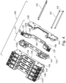
- FIG. 3 is an exploded, rear perspective view of the SPD system of FIG. 1 .
- FIG. 4 is an exploded, front perspective view of a base module forming a part of the SPD system of FIG. 1 .
- FIG. 5 is a fragmentary, front perspective view of the base module of FIG. 4 .
- FIG. 6 is a fragmentary, side view of the SPD system of FIG. 1 .
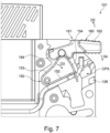
- FIG. 7 is an enlarged, fragmentary, side view of the SPD system of FIG. 1 .
- FIG. 8 is a fragmentary, rear perspective view of an SPD module forming a part of the SPD system of FIG. 1 .
- FIG. 9 is an exploded, fragmentary, front perspective view of the SPD module of FIG. 8 .
- FIG. 10 is a fragmentary, side view of the SPD module of FIG. 8 .
- FIG. 11 is a schematic view of an electrical power supply system including the the SPD system of FIG. 1 .
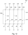
- FIG. 12 is a schematic diagram representing the unprotected feedthrough circuit of FIG. 2 .
- FIG. 13 is a schematic diagram representing the protected feedthrough circuit of FIG. 1 .
Detailed Description of Embodiments
-
The present invention now will be described more fully hereinafter with reference to the accompanying drawings, in which illustrative embodiments of the invention are shown. In the drawings, the relative sizes of regions or features may be exaggerated for clarity. This invention may, however, be embodied in many different forms and should not be construed as limited to the embodiments set forth herein; rather, these embodiments are provided so that this disclosure will be thorough and complete, and will fully convey the scope of the invention to those skilled in the art.
-
It is noted that aspects described with respect to one embodiment may be incorporated in different embodiments although not specifically described relative thereto. That is, all embodiments and/or features of any embodiments can be implemented separately or combined in any way and/or combination. Moreover, other apparatus, methods, and systems according to embodiments of the inventive concept will be or become apparent to one with skill in the art upon review of the following drawings and detailed description. It is intended that all such additional apparatus, methods, and/or systems be included within this description, be within the scope of the present inventive subject matter, and be protected by the accompanying claims.
-
As used herein, "monolithic" means an object that is a single, unitary piece formed or composed of a material without joints or seams. Alternatively, a unitary object can be a composition composed of multiple parts or components secured together at joints or seams.
-
Embodiments of the inventive concept are described herein with respect to surge protection for electrical power transmission cables. An "electrical power transmission cable" as used herein means any kind of medium configured to carry electrical power from a power supply to a device or equipment that consumes the electrical power.
-
Referring to FIGS. 1-13 , a surge protective device (SPD) system 101 according to some embodiments of the inventive concept is shown therein. The SPD system 101 is a feed-through terminal block system including a feed-through terminal block and a user-removable SPD, the SPD including an overvoltage protection component (e.g., a varistor). The feed-through terminal block is a first module and the SPD is a second module that is pluggable into and removable from the first module.
-
The SPD system 101 is modular and includes an SPD module 200 (as the second module) and a pedestal or base module 100 (as the first module). The base module 100 is a feed-through terminal block. The SPD module 200 is pluggable into and removable from the base module 100. The SPD module 200 can be removed and replaced in the event an electrical component of the SPD module 200 fails or when overvoltage protection is not needed. When the SPD module 200 is plugged into the base module 100 as described and shown herein, the SPD module 200 and the base module 100 together form an SPD assembly or unit 103.
-
With reference to FIG. 11 , the SPD system 101 is configured for use in and, in some embodiments forms a part of, an electrical power supply system 10. The illustrated electrical power supply system 10 according to some embodiments is a three-phase electrical power supply system. The illustrated electrical power supply system 10 includes a power supply 12, a power load 14 (e.g., equipment), three feed or input lines or cables L1, L2, L3 (corresponding to each of the three phases), an input neutral line or cable LN, an input ground or protective earth line or cable LP, three output lines or cables L1X, L2X, L3X, an input neutral line or cable LNX, and an output ground or protective earth line or cable LPX. The base module 100 is in electrical series between the power supply 12 and the equipment 14 to be protected. The SPD module 200, when installed on the base module 100, is connected in electrical parallel with the equipment to be protected and is operative to divert surge current to ground.
-
In some embodiments and with reference to FIG. 6 , the cables L1, L2, L3, LN, LP, L1X, L2X, L3X, LNX, LPX are insulated cables including an electrical conductor 22 and a surrounding insulation layer 24.
-
The base module 100 ( FIGS. 2-7 ) includes a base module circuit ECB ( FIG. 12 ). The base module circuit ECB includes five feed-through circuits FC1, FC2, FC3, FCN, FCP. The SPD module 200 includes an SPD module circuit ECM ( FIG. 13 ). The SPD assembly 103 embodies an SPD circuit ECA ( FIG. 13 ) including both the base module circuit ECB and the SPD module circuit ECM, which are electrically interconnected in the SPD circuit ECA. The SPD module circuit ECM as illustrated and described is an example surge protective circuit and other surge protective circuit configurations may be provided instead in accordance with embodiments of the technology.
-
The base module 100 is adapted to receive and electrically connect the input cables L1, L2, L3, LN, LP and output cables L1X, L2X, L3X, LNX, LPX with the base module circuit ECB, and also with the SPD module circuit ECM when the SPD module 200 is installed in the base module 100. In the illustrative example, the cables L1, L1X are connected to a first electrical phase line, the cables L2, L2X are connected to a second electrical phase line, the cables L3, L3X are connected to a third electrical phase line, the cables LN, LNX are connected to a neutral line, and the cables LP, LPX are connected to an electrical ground or protective earth line, of a three-phase electrical power transmission system.
-
When the cables L1, L2, L3, LN, LP, L1X, L2X, L3X, LNX, LPX are connected to the base module 100 with the SPD module 200 not installed in the base module 100, an unprotected installed feedthrough circuit ECF ( FIGS. 2 and 12 ) is thereby formed. When the cables L1, L2, L3, LN, LP, L1X, L2X, L3X, LNX, LPX are connected to the base module 100 with the SPD module 200 installed in the base module 100, a surge protected installed feedthrough circuit ECS ( FIGS. 1 and 13 ) is thereby formed.
-
The SPD system 101 may further include a remote monitoring device 30 ( FIG. 13 ). As discussed herein, the remote monitoring device 30 can be electrically connected to the SPD module 200 to monitor a state of the SPD module 200. The SPD system 101 and the remote monitoring device 30 together form a remote monitoring system.
-
The illustrated SPD assembly 103 is configured to be mounted on a DIN rail 20. However, other mounting and protection configurations may be provided in accordance with some embodiments of the technology.
-
According to some embodiments and as shown, the base module 100 is configured, sized and shaped for mounting on a support rail 20 (shown in dashed lines). According to some embodiments, the support rail 20 is a DIN (Deutsches Institut für Normung e.V.) rail shown in FIGS. 1 and 2 and is compliant with corresponding applicable DIN requirements or standards. According to some embodiments, the support rail 20 is a DIN top hat rail having a width of 35 mm and a depth of 7.5 mm. The DIN rail 20 has a lengthwise axis B-B. The DIN rail 20 may be secured (e.g., by screws or other fasteners) to a suitable support structure such as a wall, for example, a rear wall of an electrical service utility cabinet. The base module 100 is removably mountable on the DIN rail 20. The pluggable SPD module 200 is in turn removably mountable on the base module 100.
-
In some embodiments, the maximum dimensions of the SPD assembly 103 are compliant with DIN (Deutsches Institut für Normung e.V.) Standard: DIN EN 60715:2017. In some embodiments, the maximum dimensions of the assembly 103 are compliant with each of these standards.
-
The base module 100 includes a housing 110, an DIN rail latching mechanism 102, five electrical feed-through assemblies F1, F2, F3, FN, FP, and a pair of connector operating mechanisms 161 associated with each feed-through assembly F1, F2, F3, FN, FP. The base module 100 has a fore-aft or SPD module receiving or plug-in axis A-A that extends transversely to and, in some embodiments, substantially perpendicular to the lengthwise axis B-B the DIN rail 20.
-
According to some embodiments, the housing 110 is formed of an electrically insulating polymeric material. The housing 110 may be formed of any suitable material or materials. In some embodiments, the housing 110 is formed of a rigid polymeric material or metal (e.g., aluminum). Suitable polymeric materials may include polyamide (PA), polypropylene (PP), polyphenylene sulfide (PPS), or ABS, for example.
-
The base housing 110 includes five subhousings 112 ( FIG. 4 ) secured together by screws 115 to form a rigid unit. The subhousings 112 may be substantially identical. One of the subhousings 112 is shown exploded in FIG. 4 and is described below. It will be appreciated that this description also applies to the other subhousings 112.
-
The subhousing 112 includes a pair of opposed housing parts 114 that define an enclosed cavity 124. The subhousing 112 includes outer sections 116, 116X and an inner section 118 that define a seat or slot 119. The slots 119 combine in the housing 110 to define a front-facing module plug-in seat or slot 120. A DIN rail slot 122 is defined on the rear side. A cable receiving port 126 is defined in each outer section 116, 116X. One cable port 126 is provided for each of the cables L1, L2, L3, LN, LP, L1X, L2X, L3X, LNX, LPX. Two connector receiving ports 128 are defined in the inner section 118.
-
Each of the feed-through assemblies F1, F2, F3, FN, FP is contained in the cavity 124 of a respective one of the subhousings 112. Each feed-through assembly F1, F2, F3, FN, FP and its subhousing 112 form a subunit 111. The feed-through assembles F1, F2, F3, FN, and FP form the feed-through electrical circuits FC1, FC2, FC3, FCN, and FCP, respectively.
-
The feed-through assemblies F1, F2, F3, FN, FP may be substantially identical. The feed-through assembly FP is shown in FIG. 4 and is described below. It will be appreciated that this description also applies to the other feed-through assemblies F1, F2, F3, FN.
-
The feed-through assembly FP includes a main conductor member 140 and a pair of connector springs 150.
-
The main conductor member 140 has an input end section 142, an output end section 142X, and a bridge section 144. Two module connection slots RP are formed in the bridge section 144. The feed-through assemblies F1, F2, F3, FN include pairs of connection slots R1, R2, R3, RN, respectively.
-
The main conductor member 140 may be formed of any suitable metal. In some embodiments, the main conductor member 140 is formed of copper or steel.
-
Each connector spring 150 includes a pair of cantilevered spring legs 152, 153 a contact leg 154, and an opening 156. Connector spring 150 The connector spring 150 may be formed of any suitable metal. In some embodiments, the connector spring 150 is formed of copper or steel.
-
The input end section 142 and the connector spring 150 mounted thereon form an input connector CP. The output end section 144 and the connector spring 150 mounted thereon form an input connector CPX. Similarly, the end sections of the conductor members 140 of the feed-through assemblies F1, F2, F3, and FN and the springs 150 mounted thereon form input connectors C1, C2, C3, and CN and output connectors C1X, C2X, C3X, and CNX, as shown in FIG. 5 .
-
The end section 142 or 144 extends through the opening 156. The spring leg's 150 outer spring leg 153 is elastically deflectable so that the contact leg 154 can be positioned between a relaxed position as shown in FIG. 7 and an open or receiving position as shown in FIG. 6 .
-
In some embodiments, the input connectors and output connectors are operated using a connector operating mechanism 161. A connector operating mechanism 161 is provided for each connector C1, C2, C3, CN, CP, C1X, C2X, C3X, CNX, and CPX. Each operating mechanism 161 includes a pivot hole 129 and a lever member 160. The lever member 160 includes a handle section 162 and a bearing section 164. A driver slot 163 is provide in the handle section 162.
-
In use, the cables L1, L2, L3, LN, LP, L1X, L2X, L3X, LNX, LPX can be electrically connected and secured by the connectors C1, C2, C3, CN, CP, C1X, C2X, C3X, and CNX, CPX as follows. The lever member 160 is pivoted in an opening direction D2 as indicated in FIG. 7 to an upright, locked open position. By this motion, the cammed surface of the bearing section 164 deflects the spring leg 153 in a direction D3 to the open position. The bare end of the conductor 22 of the cable is inserted through the port 126 and the opening 156. The lever member 160 is then displaced in a lever closing direction D4 so that the bearing section 164 springs back in a direction D5. The spring return force of the spring 150 pulls the cable end against the rear side of the end section 142 or 144, to form an electrical mechanically connection between the cable conductor 22 and the conductor member 140, as shown in FIG. 7 .
-
The lever member 160 can be pivoted into the open position and/or into the closed position by hand. Alternatively, the operator can insert a tool (e.g., a screwdriver) into the slot 163 to apply additional leverage to the lever member 160.
-
The SPD module 200 includes a module housing 210, an electrical assembly 230, an indicator system 261, and three thermal disconnect mechanisms 280.
-
The SPD module housing 210 defines an enclosed cavity containing the electrical assembly 230. The module housing 210 has a rear end 214R, a rear section 216R and a front section 216F. A remote connector recess 218 is defined along an edge of the front section 216F. An indicator window 219 is defined in the front section 216F.
-
According to some embodiments, the housing 210 is formed of an electrically insulating polymeric material. The housing 210 may be formed of any suitable material or materials. In some embodiments, the housing 210 is formed of a rigid polymeric material or metal (e.g., aluminum). Suitable polymeric materials may include polyamide (PA), polypropylene (PP), polyphenylene sulfide (PPS), or ABS, for example.
-
With reference to FIGS. 1 and 8 -10, the illustrative electrical assembly 230 includes three varistor subassemblies 240 (which serve as overvoltage protection components), a ground busbar 250, a gas discharge tube (GDT) 254, and a ground or protective earth (PE) electrode 256.
-
Each varistor subassembly 240 includes an overvoltage clamping element 242, a metal first or line electrode 244, a metal second or ground electrode 246 and an electrically insulating cover 247 (e.g., epoxy). The cover 247 is not shown in FIG. 9 . In some embodiments and as illustrated, the overvoltage clamping element is a varistor 242.
-
The varistor 242 has opposed contact surfaces 242A, 242B. Metallization layers may cover the contact surfaces 242A, 242B.
-
The thickness of each of the varistor 242 and the dimensions of its contact surfaces 242A, 242B will depend on the varistor characteristics desired for the particular application.
-
The varistor material of the varistor 242 may be any suitable material conventionally used for varistors, namely, a material exhibiting a nonlinear resistance characteristic with applied voltage. In some embodiments, the varistor 242 is a metal oxide varistor (MOV). In some embodiments, the resistance becomes very low when a prescribed voltage is exceeded. The varistor material may be a doped metal oxide or silicon carbide, for example. Suitable metal oxides include zinc oxide compounds.
-
Each line electrode 244 includes a contact portion 244A and an integral line contact connector B1, B2 or B3. Each ground electrode 246 includes a contact portion 246A, and an integral tab 247.
-
The ground busbar 250 includes three disconnect spring legs 252 and a neutral contact connector BN.
-
The PE electrode 256 includes a contact portion 256A and a PE contact connector BP.
-
In some embodiments and as illustrated, each of the connectors B1, B2 B3, BN, BP is a blade spring connector.
-
The electrodes 244, 246, 256 and the neutral busbar 250 are electrically conductive. In some embodiments, the electrodes 244, 246, 256 and the neutral busbar 250 are formed of metal. Suitable metals may include nickel brass or copper alloys such as CuSn 6 or Cu - ETP. In some embodiments, each of the electrodes 244, 246, 256 and the neutral busbar 250 is unitary (composite or monolithic) and, in some embodiments, monolithic.
-
As will be appreciated from FIGS. 8 , 9 and 13 , each connector B1, B2 B3 is connected to the ground busbar 250 through a varistor 242, and the connectors B1, B2, B3, BN are connected in parallel to the PE connector BP through the GDT 254.
-
Each thermal disconnector mechanism 280 includes one of the disconnect springs 252, a mating one of the tabs 247 and a layer of a meltable bonding agent (e.g., solder) 282. The solders 282 affix the free end of each disconnect spring 252 to its respective tab 247 such that the spring 252 is held in an elastically deflected state.
-
The indicator system 261 includes a remote indictor assembly 260 and a local indicator assembly 270.
-
The remote indicator assembly 260 includes a switch 262 and an electrical connector 264 connected to the switch 262. The remote indicator connector 264 is mounted in the remote connector recess 218 of the SPD module housing 210. In some embodiments (for example, as illustrated), the remote indicator connector 264 is accessible from outside the feed-through SPD assembly/unit 103. In some embodiments, the remote indicator connector 264 is substantially fully disposed within the footprint of the SPD module housing 210.
-
The local indicator assembly 270 includes an actuator member 272. The actuator member 272 includes three primary legs 272A, a secondary leg 272B and an indicator portion 272C. Each leg 272A is positioned adjacent a respective spring 252.
-
As discussed herein, the feed-through SPD system 101 is adapted to be integrated into and provide overvoltage surge protection for an electrical power supply transmission system (e.g., system 10).
-
In some embodiments, the SPD module 200 is rated according to IEC 61643-11:2011 (dated 9 March 2011) for at least 20kA nominal discharge current (In).
-
In some embodiments, the base module 100 is a feed-through terminal block rated according to International Electrotechnical Commission (IEC) standard 60947-1-7:2009 to sustain at least 80 Amps as a continuous load current.
-
In some embodiments, the SPD module 200 is a Type 1 Surge Protective Device according to IEC 61643-11:2011. In some embodiments, the SPD module 200 is a Type 2 Surge Protective Device according to IEC 61643-11:2011.
-
In some embodiments, connectors C1, C2, C3, CN, CP, C1X, C2X, C3X, CNX, CPX of the base module 100 are configured to accept or receive and electrically connect electrical power transmission cables having a cross-sectional area of 2 mm2 or greater. In some embodiments, connectors C1, C2, C3, CN, CP, C1X, C2X, C3X, CNX, CPX are configured to accept or receive and electrically connect electrical power transmission cables having a cross-sectional area of 4 mm2 or greater. In some embodiments, connectors C1, C2, C3, CN, CP, C1X, C2X, C3X, CNX, CPX are configured to accept or receive and electrically connect electrical power transmission cables having a cross-sectional area of 6 mm2 or greater.
-
The feed-through SPD system 101 may be used as follows in accordance with some embodiments. The feed-through SPD system 101 is configured to be mounted on the DIN rail and to protect a three-phase system using a "3+1" protection configuration. However, other mounting and protection configurations may be provided in accordance with some embodiments of the technology.
-
In some embodiments, the electrical power supply transmission system 10 is a TN-S, TN-C, TT power supply system as defined by the IEC.
-
In use, the base module 100 is mounted on the DIN rail 20 as shown in FIGS. 1 and 2 .
-
The conductors 22 of the cables L1, L2, L3, LN, LP, L1X, L2X, L3X, LNX, and LPX are inserted through the cable ports 126 and secured in the connectors C1, C2, C3, CN, CP, C1X, C2X, C3X, CNX, and CPX, respectively.
-
The feed-through SPD system 101 may be used in an unprotected feed-through configuration and mode of operation and, alternatively, in a protected feed-through configuration and mode of operation. When the SPD module 200 is not installed in the base module 100, the feed-through SPD system 101 operates in the unprotected feed-through mode. When the SPD module 200 is installed in the base module 100 and is a ready state, the feed-through SPD system 101 operates in the protected feed-through mode.
-
The feed-through SPD system 101 is shown in FIG. 2 in the unprotected feed-through configuration. In the unprotected feed-through configuration, the cables L1, L2, L3, LN, LP, L1X, L2X, L3X, LNX, and LPX are connected to the base module 100 and the SPD module 200 not operatively installed on the base module 100 (i.e., the connectors B1, B2, B3, BN, BP are not mated with the slots R1, R2, R3, RN, RP of the feed-through assemblies F1, F2, F3, FN, FP).
-
FIG. 12 is a schematic view representing an electrical circuit including the base module 100 and the cables L1, L2, L3, LN, LP, L1X, L2X, L3X, LNX, and LPX in the unprotected feed-through configuration. In the unprotected feed-through configuration or mode, the base module 100 serves as an electrical feed-through terminal or bridge. The lines L1, L2, L3, LN, LP, L1X, L2X, L3X, LNX, and LPX are not provided with surge protection by the SPD module 200.
-
As show in FIG. 2 , when the SPD module 200 is not seated in the slot 120, the connector receiving ports 128 remain unoccupied and open. According to some embodiments, the base module 100 is constructed such that the base module 100 in this configuration is compliant with IP Code 20 (IP20) as defined by International Electrotechnical Commission (IEC) standard IEC 60529:1989 + AMD1:1999 + AMD2:2013.
-
The feed-through SPD system 101 is shown in FIG. 1 in the alternative protected feed-through configuration. In the protected feed-through configuration, the cables L1, L2, L3, LN, LP, L1X, L2X, L3X, LNX, and LPX are connected to the base module 100 by the connectors C1, C2, C3, CN, CP, C1X, C2X, C3X, CNX, and CPX, respectively, and the SPD module 200 is operatively installed on the base module 100, thereby forming the feed-through SPD assembly/unit 103. The rear section 216R is seated in the slot 120 and the connectors B1, B2, B3, BN, BP are mated with the slots R1, R2, R3, RN, RP of the feed-through assemblies F1, F2, F3, FN, FP). More particularly, the connectors B1, B2, B3, BN, and BP are each received in a slot R1, R2, R3, RN, and RP, respectively, to make direct and reliable electrical contact with between the connector B1, B2, B3, BN, BP and the corresponding conductor member 140. If the connectors B1, B2, B3, BN, BP are spring connectors, they are elastically reflected in their inserted, mated condition.
-
In some embodiments, in the protected feed-through configuration, a monitoring line 32 is connected to the SPD module 200 via the remote monitoring connector 264. The monitoring line 32 connects the SPD module 200 to the remote monitoring device 30.
-
FIG. 13 is a schematic view representing an electrical circuit including the feed-through SPD assembly/unit 103 and the cables L1, L2, L3, LN, LP, L1X, L2X, L3X, LNX, and LPX in the protected feed-through configuration.
-
In protected feed-through configuration or mode, the SPD assembly/unit 103 serves as an electrical feed-through terminal or bridge, and the lines L1, L2, L3, LN, LP, L1X, L2X, L3X, LNX, and LPX are provided with surge protection by the SPD module 200. The varistors 242 along with the GDT 254 together form a three-phase surge protective or overvoltage protection circuit ECM. However, other configurations of protective circuits may be provided in other embodiments (e.g., 3+0, 4+0, 1+0, 1+0, 2+0, 1+1, etc. according to IEC 61643-11:2011 and IEC 61643-12:2020). While the varistors 242 are provided as the overvoltage protection components of the SPD module 200, in other embodiments overvoltage protection components other than varistors may be used. Such other overvoltage protection components may include spark gaps, diodes, thyristors, etc.
-
In use, each thermal disconnect mechanism 280 serves as a fail-safe mechanism that is actuated in response to heat generated in the SPD module 200. In some embodiments, actuation of the thermal disconnect mechanism 280 will in turn actuate the indicator system 261 to alert an operator that the thermal disconnect mechanism 280 has been triggered.
-
As is well known, a varistor has an innate nominal clamping voltage VNOM (sometimes referred to as the "breakdown voltage" or simply the "varistor voltage") at which the varistor begins to conduct current. Below the VNOM, an ideal varistor will not pass current, but in practice may pass a leakage current. Above the VNOM, the varistor will conduct a current (i.e., a leakage current or a surge current). The VNOM of a varistor is typically specified as the measured voltage across the varistor with a DC current of 1mA.
-
As is known, a varistor has three modes of operation. In a first normal mode (discussed above), up to a nominal voltage, the varistor is practically an electrical insulator. In a second normal mode (also discussed above), when the varistor is subjected to an overvoltage, the varistor temporarily and reversibly becomes an electrical conductor during the overvoltage condition and returns to the first mode thereafter. In a third mode (the so-called end of life mode), the varistor is effectively depleted and becomes a permanent, non-reversible electrical conductor.
-
The varistor also has an innate clamping voltage VC (sometimes referred to as simply the "clamping voltage"). The clamping voltage VC is defined as the maximum voltage measured across the varistor when a specified current is applied to the varistor over time according to a standard protocol.
-
In the absence of an overvoltage condition, each varistor 242 provides high resistance such that no current flows through the varistor 242 as it appears electrically as an open circuit. That is, ordinarily the varistor 242 passes no current. The terminals 244, 246 are electrically isolated from one another by the varistor 242. In the event of an overcurrent surge event (typically transient; e.g., lightning strike) or an overvoltage condition or event (typically longer in duration than an overcurrent surge event) exceeding VNOM, the resistance of the varistor 242 decreases rapidly, allowing current to flow through the varistor 242 and create a shunt path for current flow to ground via the connector BP and the main conductor 140 of the feed-through assembly FP. Normally, the varistors 242 recover from these events without significant overheating of the varistor.
-
The VNOM of a given varistor begins at a certain value and over time could degrade to a lower effective VNOM value as a result of varistor aging. Typically, a varistor is initially rated for a "maximum continuous operating voltage" (MCOV), indicating that the VNOM of the varistor exceeds the rated MCOV when first placed in service.
-
Varistor aging (i.e, degradation resulting in reduction of the VNOM) can be caused by surge currents (during overvoltage events) or continuous leakage currents (during normal operation of the power system) applied to the varistor in service, as well as by passage of time with the nominal voltage applied on the varistor (rare case, typically caused by low quality varistors). Aging degradation is generally thermally induced.
-
As a result, in an end of life condition, a fault current will continuously flow through the varistor 242 even in the absence of an overvoltage condition. In this case, the current may continue to flow through the varistor 242, thereby generating heat from ohmic losses in the varistor 242. If the condition was permitted to persist, exces heat may be generated in the varistor 242.
-
Varistors have multiple failure modes. The failure modes include: 1) the varistor fails as a short circuit; and 2) the varistor fails as a linear resistance. The failure of the varistor to a short circuit or to a linear resistance may be caused by the conduction of a single or multiple surge currents of sufficient magnitude and duration or by a single or multiple continuous overvoltage events that will drive a sufficient current through the varistor.
-
A short circuit failure typically manifests as a localized pinhole or puncture site (herein, "the failure site") extending through the thickness of the varistor. This failure site creates a path for current flow between the two electrodes of a low resistance, but high enough to generate ohmic losses and cause overheating of the device even at low fault currents. Sufficiently large fault current through the varistor can melt the varistor in the region of the failure site and generate an electric arc.
-
A varistor failure as a linear resistance will cause the conduction of a limited current through the varistor that will result in a buildup of heat. This heat buildup may result in catastrophic thermal runaway and the device temperature may exceed a prescribed maximum temperature. For example, the maximum allowable temperature for the exterior surfaces of the device may be set by code or standard to prevent combustion of adjacent components. If the leakage current is not interrupted at a certain period of time, the overheating will result eventually in the failure of the varistor to a short circuit as defined above.
-
In some cases, the current through the failed varistor could also be limited by the power system itself (e.g., ground resistance in the system or in photo-voltaic (PV) power source applications where the fault current depends on the power generation capability of the system at the time of the failure) resulting in a progressive build up of temperature, even if the varistor failure is a short circuit. There are cases where there is a limited leakage current flow through the varistor due to extended in time overvoltage conditions due to power system failures, for example. These conditions may lead to temperature build up in the device, such as when the varistor has failed as a linear resistance and could possibly lead to the failure of the varistor either as a linear resistance or as a short circuit as described above.
-
In some cases, the varistor 242 may assume an "end of life" mode in which the varistor 242 is depleted in full or in part (i.e, in an "end of life" state), leading to an end of life failure. When the varistor 242 reaches its end of life, the varistor 242 will become substantially a short circuit with a very low but non-zero ohmic resistance.
-
As a result, in an end of life condition, a fault current will continuously flow through the varistor 242 even in the absence of an overvoltage condition. In this case, the current may continue to flow through the varistor 242, thereby generating heat from ohmic losses in the varistor 242 . If the condition was permitted to persist, the heat generated in the varistor 242 and the SPD module 200 could build up until the SPD module 200 or part thereof melts or explodes. Such an event may be regarded as catastrophic. If the fault current were of sufficient magnitude, the fault current may induce or generate electric arcing through and around the varistor 242 (herein, an "arcing event"). Such an arcing event may rapidly generate additional heat in the SPD module 200. Such an arcing event may rapidly generate additional heat in the SPD module 200 and/or may cause localized damage to other components of the feed-through SPD assembly/unit 103.
-
In the case of the SPD module 200, each thermal disconnect mechanism 280 is adapted and configured to electrically disconnect the corresponding varistor 242 from the ground line LPX (and thereby from the power load) to prevent or reduce the generation of heat in the varistor. In this way, the thermal disconnect mechanism 280 can operate as a switch to prevent overheating and catastrophic failure as described above.
-
More particularly, during normal operation, the thermal disconnector mechanism 280 remains in a ready position ( FIGS. 8 and 10 ) with the spring 252 bonded to and in electrical continuity with the tab 247 by the solder 282. In this normal mode, each varistor 242 is an insulator up to the nominal clamping voltage VNOM. In the case of a surge event and when the varistors 242 is not in an end of life state, the heat generated in the varistor 242 is not sufficient to melt the solder 282. However, when a varistor fails (as described above) or assumes an end of life state, overheating of one of the varistors 242 will sufficiently heat its solder 282 to cause its solder 282 to melt and release the elastically deflected leg 252 from its tab 247. The corresponding varistor 242 is thereby disconnected from the ground terminal BP. In some embodiments, the remaining legs 252 will remain affixed to their tabs 247 by the solders 282 so that the associated lines continue to be overvoltage protected by their associated varistors 242.
-
In some embodiments, the actuation of any of the thermal disconnect mechanisms 280 also actuates the remote indicator assembly 260 and/or the local indicator assembly 270 to signal to an observer that a varistor 242 has failed. In some embodiments, the actuation of any one of the thermal disconnect mechanisms 280 actuates both the remote indicator assembly 260 and the local indicator assembly 270.
-
Upon actuation of a thermal disconnect mechanism 280, the released leg 252 will forcibly displace the legs 272A, 272B from the ready position ( FIG. 10 ) in a direction D5. This in turn displaces the indicator 272C into a location visible through the window 219. This provides a visual alert or indication on the SPD module 200 so that an operator can readily determine that the SPD module 200 has assumed a failed state.
-
The displacement of the leg 272B will also actuate or change the state of the remote signaling switch 262. The change of state of the switch 262 is transmitted to the remote monitoring device 30 via the remote signal connector 264.
-
The terminology used herein is for the purpose of describing particular aspects only and is not intended to be limiting of the disclosure. As used herein, the singular forms "a", "an" and "the" are intended to include the plural forms as well, unless the context clearly indicates otherwise. It will be further understood that the terms "comprises" and/or "comprising," when used in this specification, specify the presence of stated features, integers, steps, operations, elements, and/or components, but do not preclude the presence or addition of one or more other features, integers, steps, operations, elements, components, and/or groups thereof. As used herein, the term "and/or" includes any and all combinations of one or more of the associated listed items. Like reference numbers signify like elements throughout the description of the figures.
-
It will be understood that, although the terms "first," "second," etc. may be used herein to describe various elements, these elements should not be limited by these terms. These terms are only used to distinguish one element from another. Thus, a first element could be termed a second element without departing from the teachings of the inventive subject matter.
-
Unless otherwise defined, all terms (including technical and scientific terms) used herein have the same meaning as commonly understood by one of ordinary skill in the art to which this inventive concept belongs. It will be further understood that terms, such as those defined in commonly used dictionaries, should be interpreted as having a meaning that is consistent with their meaning in the context of the relevant art and this specification and will not be interpreted in an idealized or overly formal sense unless expressly so defined herein.
-
Aspects and embodiments of the invention will be further understood with reference to the following non-limiting numbered clauses:
- 1. A surge protective device (SPD) system for use with an input cable and an output cable of an electrical power supply transmission system, the SPD system comprising:
- a base module configured as a feed-through terminal block, the base module including a feed-through circuit including:
- an input connector configured to connect the input cable; and
- an output connector configured to connect the output cable and electrically connected to the input connector; and
- an SPD module configured to be removably mounted on the base module, the SPD module including an SPD circuit including an overvoltage protection component;
- wherein the SPD system is configured to be used in each of:
- a protected mode, wherein the SPD module is mounted on the base module and provides overvoltage protection to the feed-through circuit; and
- an unprotected mode, wherein the SPD module is not mounted on the base module and the base module operates as a feed-through terminal block without overvoltage protection from the SPD module; and
- wherein the SPD module is a Type 1 or Type 2 Surge Protective Device according to International Electrotechnical Commission (IEC) standard 61643-11:2011 (dated 9 March 2011).
- 2. The SPD system of Clause 1 wherein the base module is a feed-through terminal block rated according to IEC 60947-1-7:2009 to sustain at least 80 Amps as a continuous load current.
- 3. The SPD system of any one of Clauses 1 to 2 wherein the SPD module is rated according to IEC 61643-11:2011 for at least 20kA nominal discharge current (In).
- 4. The SPD system of any one of Clauses 1 to 3 wherein the input connector and the output connector are each configured to accept or receive and electrically connect electrical power transmission cables having a cross-sectional area of 2 mm2 or greater.
- 5. The SPD system of any one of Clauses 1 to 4 wherein the overvoltage protection component is a varistor.
- 6. The SPD system of Clause 5 wherein the SPD module includes a thermal disconnect mechanism configured to disconnect the varistor in response to overheating of the SPD module.
- 7. The SPD system of Clause 6 wherein the SPD module includes an indicator system configured to provide an alert in response to actuation of the thermal disconnect mechanism.
- 8. The SPD system of Clause 7 wherein the indicator system includes a remote indicator system including:
- a switch; and
- a remote monitoring connector forming a part of the SPD module.
- 9. The SPD system of any one of Clauses 1 to 8 wherein:
- the feed-through circuit includes a conductor member electrically connecting the output connector to the input connector; and
- the SPD module includes a connector that directly contacts the conductor member to connect the overvoltage protection component to the feed-through circuit.
- 10. The SPD system of any one of Clauses 1 to 9 wherein:
- a first portion of the conductor member forms a part of the input connector; and
- a second portion of the conductor member forms a part of the output connector.
- 11. The SPD system of Clause 10 wherein:
- the input connector and the output connector are spring clamp connectors; and
- the input connector and the output connector are each provided with a connector operating mechanism including a lever member operable to open the spring clamp connector to receive the input or output cable.
- 12. The SPD system of any one of Clauses 1 to 11 wherein the base module is configured to be mounted on a DIN rail.
- 13. The SPD system of any one of Clauses 1 to 12 wherein:
- the base module is configured for use with a plurality of pairs of input and output cables, and includes a plurality of feed-through circuits each including:
- an input connector configured to connect a corresponding input cable; and
- an output connector configured to connect a corresponding output cable and electrically connected to the respective first input connector; and
- when the SPD system is the protected mode, the SPD module provides overvoltage protection to each of the plurality of feed-through circuits.
- 14. The SPD system of any one of Clauses 1 to 13 wherein the plurality of feed-through circuits includes a feed-through circuit for each of three phase lines, a neutral line, and a protective earth line.
- 15. A surge protective device (SPD) system for use with an input cable and an output cable of an electrical power supply transmission system, the SPD system comprising:
- a base module configured as a feed-through terminal block, the base module including a feed-through circuit including:
- an input connector configured to connect the input cable; and
- an output connector configured to connect the output cable and electrically connected to the input connector; and
- an SPD module configured to be removably mounted on the base module, the SPD module including an SPD circuit including an overvoltage protection component;
- wherein the SPD system is configured to be used in each of:
- a protected mode, wherein the SPD module is mounted on the base module and provides overvoltage protection to the feed-through circuit; and
- an unprotected mode, wherein the SPD module is not mounted on the base module and the base module operates as a feed-through terminal block without overvoltage protection from the SPD module; and
- wherein the base module is a feed-through terminal block rated according to IEC 60947-1-7:2009 to sustain at least 80 Amps as a continuous load current.
- 16. A surge protective device (SPD) system for use with an input cable and an output cable of an electrical power supply transmission system, the SPD system comprising:
- a base module configured as a feed-through terminal block, the base module including a feed-through circuit including:
- an input connector configured to connect the input cable; and
- an output connector configured to connect the output cable and electrically connected to the input connector; and
- an SPD module configured to be removably mounted on the base module, the SPD module including an SPD circuit including an overvoltage protection component;
- wherein the SPD system is configured to be used in each of:
- a protected mode, wherein the SPD module is mounted on the base module and provides overvoltage protection to the feed-through circuit; and
- an unprotected mode, wherein the SPD module is not mounted on the base module and the base module operates as a feed-through terminal block without overvoltage protection from the SPD module; and
- wherein the SPD module is rated according to IEC 61643-11:2011 for at least 20kA nominal discharge current (In).
- 17. A surge protective device (SPD) system for use with an input cable and an output cable of an electrical power supply transmission system, the SPD system comprising:
- a base module configured as a feed-through terminal block, the base module including a feed-through circuit including:
- an input connector configured to connect the input cable; and
- an output connector configured to connect the output cable and electrically connected to the input connector; and
- an SPD module configured to be removably mounted on the base module, the SPD module including an SPD circuit including an overvoltage protection component;
- wherein the SPD system is configured to be used in each of:
- a protected mode, wherein the SPD module is mounted on the base module and provides overvoltage protection to the feed-through circuit; and
- an unprotected mode, wherein the SPD module is not mounted on the base module and the base module operates as a feed-through terminal block without overvoltage protection from the SPD module; and
- wherein the input connector and the output connector are each configured to accept or receive and electrically connect electrical power transmission cables having a cross-sectional area of 2 mm2 or greater.
- 18. A surge protective device (SPD) system for use with an input cable and an output cable of an electrical power supply transmission system, the SPD system comprising:
- a base module configured as a feed-through terminal block, the base module including a feed-through circuit including:
- an input connector configured to connect the input cable; and
- an output connector configured to connect the output cable and electrically connected to the input connector; and
- an SPD module configured to be removably mounted on the base module, the SPD module including an SPD circuit including an overvoltage protection component;
- wherein the SPD system is configured to be used in each of:
- a protected mode, wherein the SPD module is mounted on the base module and provides overvoltage protection to the feed-through circuit; and
- an unprotected mode, wherein the SPD module is not mounted on the base module and the base module operates as a feed-through terminal block without overvoltage protection from the SPD module; and
- wherein:
- the overvoltage protection component is a varistor;
- the SPD module includes a thermal disconnect mechanism configured to disconnect the varistor in response to overheating of the SPD module;
- the SPD module includes an indicator system configured to provide an alert in response to actuation of the thermal disconnect mechanism; and
- the indicator system includes a remote indicator system including:
- a switch; and
- a remote monitoring connector forming a part of the SPD module.
- 19. An electrical power supply system comprising:
- an electrical power supply;
- a surge protective device (SPD) system;
- an input cable connecting the electrical power supply to the SPD unit; and
- an output cable connecting the SPD unit to an electrical power load;
- wherein the SPD system includes:
a base module configured as a feed-through terminal block, the base module including a feed-through circuit including:
- an input connector connecting the input cable to the feed-through circuit; and
- an output connector connecting the output cable to the feed-through circuit and electrically connected to the input connector; and
- an SPD module removably mounted on the base module, the SPD module including an SPD circuit including an overvoltage protection component;
- wherein the SPD system is configured to be used in each of:
- a protected mode, wherein the SPD module is mounted on the base module and provides overvoltage protection to the feed-through circuit; and
- an unprotected mode, wherein the SPD module is not mounted on the base module and the base module operates as a feed-through terminal block without overvoltage protection from the SPD module; and
- wherein the SPD module is a Type 1 or Type 2 Surge Protective Device according to International Electrotechnical Commission (IEC) standard 61643-11:2011 (dated 9 March 2011).
- 20. An electrical power supply system comprising:
- an electrical power supply;
- a surge protective device (SPD) system;
- an input cable connecting the electrical power supply to the SPD unit; and
- an output cable connecting the SPD unit to an electrical power load;
- wherein the SPD system includes:
- a base module configured as a feed-through terminal block, the base module including a feed-through circuit including:
- an input connector connecting the input cable to the feed-through circuit; and
- an output connector connecting the output cable to the feed-through circuit and electrically connected to the input connector; and an SPD module removably mounted on the base module, the SPD module including an SPD circuit including an overvoltage protection component;
- wherein the SPD system is configured to be used in each of:
- a protected mode, wherein the SPD module is mounted on the base module and provides overvoltage protection to the feed-through circuit; and
- an unprotected mode, wherein the SPD module is not mounted on the base module and the base module operates as a feed-through terminal block without overvoltage protection from the SPD module; and
- wherein the base module is a feed-through terminal block rated according to IEC 60947-1-7:2009 to sustain at least 80 Amps as a continuous load current.
- 21. An electrical power supply system comprising:
- an electrical power supply;
- a surge protective device (SPD) system;
- an input cable connecting the electrical power supply to the SPD unit; and
- an output cable connecting the SPD unit to an electrical power load;
- wherein the SPD system includes:
- a base module configured as a feed-through terminal block, the base module including a feed-through circuit including:
- an input connector connecting the input cable to the feed-through circuit; and
- an output connector connecting the output cable to the feed-through circuit and electrically connected to the input connector; and
- an SPD module removably mounted on the base module, the SPD module including an SPD circuit including an overvoltage protection component;
- wherein the SPD system is configured to be used in each of:
- a protected mode, wherein the SPD module is mounted on the base module and provides overvoltage protection to the feed-through circuit; and
- an unprotected mode, wherein the SPD module is not mounted on the base module and the base module operates as a feed-through terminal block without overvoltage protection from the SPD module; and
- wherein the SPD module is rated according to IEC 61643-11:2011 for at least 20kA nominal discharge current (In).
- 22. An electrical power supply system comprising:
- an electrical power supply;
- a surge protective device (SPD) system;
- an input cable connecting the electrical power supply to the SPD unit; and
- an output cable connecting the SPD unit to an electrical power load;
- wherein the SPD system includes:
- a base module configured as a feed-through terminal block, the base module including a feed-through circuit including:
- an input connector connecting the input cable to the feed-through circuit; and
- an output connector connecting the output cable to the feed-through circuit and electrically connected to the input connector; and
- an SPD module removably mounted on the base module, the SPD module including an SPD circuit including an overvoltage protection component;
- wherein the SPD system is configured to be used in each of:
- a protected mode, wherein the SPD module is mounted on the base module and provides overvoltage protection to the feed-through circuit; and
- an unprotected mode, wherein the SPD module is not mounted on the base module and the base module operates as a feed-through terminal block without overvoltage protection from the SPD module; and
- wherein the input connector and the output connector are each configured to accept or receive and electrically connect electrical power transmission cables having a cross-sectional area of 2 mm2 or greater.
- 23. An electrical power supply system comprising:
- an electrical power supply;
- a surge protective device (SPD) system;
- an input cable connecting the electrical power supply to the SPD unit; and
- an output cable connecting the SPD unit to an electrical power load;
- wherein the SPD system includes:
- a base module configured as a feed-through terminal block, the base module including a feed-through circuit including:
- an input connector connecting the input cable to the feed-through circuit; and
- an output connector connecting the output cable to the feed-through circuit and electrically connected to the input connector; and
- an SPD module removably mounted on the base module, the SPD module including an SPD circuit including an overvoltage protection component;
- wherein the SPD system is configured to be used in each of:
- a protected mode, wherein the SPD module is mounted on the base module and provides overvoltage protection to the feed-through circuit; and
- an unprotected mode, wherein the SPD module is not mounted on the base module and the base module operates as a feed-through terminal block without overvoltage protection from the SPD module; and
- wherein:
- the overvoltage protection component is a varistor;
- the SPD module includes a thermal disconnect mechanism configured to disconnect the varistor in response to overheating of the SPD module;
- the SPD module includes an indicator system configured to provide an alert in response to actuation of the thermal disconnect mechanism; and
- the indicator system includes a remote indicator system including:
- a switch; and
- a remote monitoring connector forming a part of the SPD module.
-
Many alterations and modifications may be made by those having ordinary skill in the art, given the benefit of present disclosure, without departing from the spirit and scope of the invention. Therefore, it must be understood that the illustrated embodiments have been set forth only for the purposes of example, and that it should not be taken as limiting the invention as defined by the following claims. The following claims, therefore, are to be read to include not only the combination of elements which are literally set forth but all equivalent elements for performing substantially the same function in substantially the same way to obtain substantially the same result. The claims are thus to be understood to include what is specifically illustrated and described above, what is conceptually equivalent, and also what incorporates the essential idea of the invention.