EP4478512A1 - Battery pack - Google Patents
Battery pack Download PDFInfo
- Publication number
- EP4478512A1 EP4478512A1 EP23880282.1A EP23880282A EP4478512A1 EP 4478512 A1 EP4478512 A1 EP 4478512A1 EP 23880282 A EP23880282 A EP 23880282A EP 4478512 A1 EP4478512 A1 EP 4478512A1
- Authority
- EP
- European Patent Office
- Prior art keywords
- battery pack
- cover
- coupled
- pack
- battery
- Prior art date
- Legal status (The legal status is an assumption and is not a legal conclusion. Google has not performed a legal analysis and makes no representation as to the accuracy of the status listed.)
- Pending
Links
Images



Classifications
-
- H—ELECTRICITY
- H01—ELECTRIC ELEMENTS
- H01M—PROCESSES OR MEANS, e.g. BATTERIES, FOR THE DIRECT CONVERSION OF CHEMICAL ENERGY INTO ELECTRICAL ENERGY
- H01M50/00—Constructional details or processes of manufacture of the non-active parts of electrochemical cells other than fuel cells, e.g. hybrid cells
- H01M50/30—Arrangements for facilitating escape of gases
- H01M50/375—Vent means sensitive to or responsive to temperature
-
- H—ELECTRICITY
- H01—ELECTRIC ELEMENTS
- H01M—PROCESSES OR MEANS, e.g. BATTERIES, FOR THE DIRECT CONVERSION OF CHEMICAL ENERGY INTO ELECTRICAL ENERGY
- H01M50/00—Constructional details or processes of manufacture of the non-active parts of electrochemical cells other than fuel cells, e.g. hybrid cells
- H01M50/20—Mountings; Secondary casings or frames; Racks, modules or packs; Suspension devices; Shock absorbers; Transport or carrying devices; Holders
- H01M50/204—Racks, modules or packs for multiple batteries or multiple cells
- H01M50/207—Racks, modules or packs for multiple batteries or multiple cells characterised by their shape
- H01M50/211—Racks, modules or packs for multiple batteries or multiple cells characterised by their shape adapted for pouch cells
-
- H—ELECTRICITY
- H01—ELECTRIC ELEMENTS
- H01M—PROCESSES OR MEANS, e.g. BATTERIES, FOR THE DIRECT CONVERSION OF CHEMICAL ENERGY INTO ELECTRICAL ENERGY
- H01M50/00—Constructional details or processes of manufacture of the non-active parts of electrochemical cells other than fuel cells, e.g. hybrid cells
- H01M50/20—Mountings; Secondary casings or frames; Racks, modules or packs; Suspension devices; Shock absorbers; Transport or carrying devices; Holders
- H01M50/233—Mountings; Secondary casings or frames; Racks, modules or packs; Suspension devices; Shock absorbers; Transport or carrying devices; Holders characterised by physical properties of casings or racks, e.g. dimensions
- H01M50/24—Mountings; Secondary casings or frames; Racks, modules or packs; Suspension devices; Shock absorbers; Transport or carrying devices; Holders characterised by physical properties of casings or racks, e.g. dimensions adapted for protecting batteries from their environment, e.g. from corrosion
-
- H—ELECTRICITY
- H01—ELECTRIC ELEMENTS
- H01M—PROCESSES OR MEANS, e.g. BATTERIES, FOR THE DIRECT CONVERSION OF CHEMICAL ENERGY INTO ELECTRICAL ENERGY
- H01M50/00—Constructional details or processes of manufacture of the non-active parts of electrochemical cells other than fuel cells, e.g. hybrid cells
- H01M50/20—Mountings; Secondary casings or frames; Racks, modules or packs; Suspension devices; Shock absorbers; Transport or carrying devices; Holders
- H01M50/271—Lids or covers for the racks or secondary casings
-
- H—ELECTRICITY
- H01—ELECTRIC ELEMENTS
- H01M—PROCESSES OR MEANS, e.g. BATTERIES, FOR THE DIRECT CONVERSION OF CHEMICAL ENERGY INTO ELECTRICAL ENERGY
- H01M50/00—Constructional details or processes of manufacture of the non-active parts of electrochemical cells other than fuel cells, e.g. hybrid cells
- H01M50/20—Mountings; Secondary casings or frames; Racks, modules or packs; Suspension devices; Shock absorbers; Transport or carrying devices; Holders
- H01M50/289—Mountings; Secondary casings or frames; Racks, modules or packs; Suspension devices; Shock absorbers; Transport or carrying devices; Holders characterised by spacing elements or positioning means within frames, racks or packs
-
- H—ELECTRICITY
- H01—ELECTRIC ELEMENTS
- H01M—PROCESSES OR MEANS, e.g. BATTERIES, FOR THE DIRECT CONVERSION OF CHEMICAL ENERGY INTO ELECTRICAL ENERGY
- H01M50/00—Constructional details or processes of manufacture of the non-active parts of electrochemical cells other than fuel cells, e.g. hybrid cells
- H01M50/30—Arrangements for facilitating escape of gases
-
- H—ELECTRICITY
- H01—ELECTRIC ELEMENTS
- H01M—PROCESSES OR MEANS, e.g. BATTERIES, FOR THE DIRECT CONVERSION OF CHEMICAL ENERGY INTO ELECTRICAL ENERGY
- H01M50/00—Constructional details or processes of manufacture of the non-active parts of electrochemical cells other than fuel cells, e.g. hybrid cells
- H01M50/30—Arrangements for facilitating escape of gases
- H01M50/342—Non-re-sealable arrangements
-
- H—ELECTRICITY
- H01—ELECTRIC ELEMENTS
- H01M—PROCESSES OR MEANS, e.g. BATTERIES, FOR THE DIRECT CONVERSION OF CHEMICAL ENERGY INTO ELECTRICAL ENERGY
- H01M50/00—Constructional details or processes of manufacture of the non-active parts of electrochemical cells other than fuel cells, e.g. hybrid cells
- H01M50/30—Arrangements for facilitating escape of gases
- H01M50/342—Non-re-sealable arrangements
- H01M50/3425—Non-re-sealable arrangements in the form of rupturable membranes or weakened parts, e.g. pierced with the aid of a sharp member
-
- H—ELECTRICITY
- H01—ELECTRIC ELEMENTS
- H01M—PROCESSES OR MEANS, e.g. BATTERIES, FOR THE DIRECT CONVERSION OF CHEMICAL ENERGY INTO ELECTRICAL ENERGY
- H01M50/00—Constructional details or processes of manufacture of the non-active parts of electrochemical cells other than fuel cells, e.g. hybrid cells
- H01M50/30—Arrangements for facilitating escape of gases
- H01M50/394—Gas-pervious parts or elements
-
- Y—GENERAL TAGGING OF NEW TECHNOLOGICAL DEVELOPMENTS; GENERAL TAGGING OF CROSS-SECTIONAL TECHNOLOGIES SPANNING OVER SEVERAL SECTIONS OF THE IPC; TECHNICAL SUBJECTS COVERED BY FORMER USPC CROSS-REFERENCE ART COLLECTIONS [XRACs] AND DIGESTS
- Y02—TECHNOLOGIES OR APPLICATIONS FOR MITIGATION OR ADAPTATION AGAINST CLIMATE CHANGE
- Y02E—REDUCTION OF GREENHOUSE GAS [GHG] EMISSIONS, RELATED TO ENERGY GENERATION, TRANSMISSION OR DISTRIBUTION
- Y02E60/00—Enabling technologies; Technologies with a potential or indirect contribution to GHG emissions mitigation
- Y02E60/10—Energy storage using batteries
Definitions
- the present invention relates to a battery pack, characterized in that when a flame with high temperature gases occurs in any one of a plurality of battery modules accommodated therein, a screen cover is applied which is capable of extinguishing the flame so that the flame is not directly exposed to the outside.
- control means are provided to monitor and control the voltage, current, etc. of a battery pack, or means are provided to extinguish a fire from the outside when a fire occurs in a battery pack, but there is a problem that such means alone cannot provide an initial rapid and active response to a fire occurring in a battery pack.
- FIG. 1 is a perspective view of a conventional battery pack 10, including a pack case and a battery module M accommodated in an inner space of the pack case.
- a battery pack 10 of the structure described above when thermal runaway occurs in any of the battery modules M accommodated therein, flames generated by the battery modules M may be discharged to the outside through the top.
- Most battery packs 10 may further include a top cover etc. that is coupled to the pack case to cover the top of the battery modules M, but there is a significant risk that the top cover may also be damaged by exposure to the flame.
- Patent Document 1 Korean Patent Publication No. 10-2022-0004854
- the present invention was conceived to solve the above problems, and an object is to provide a battery pack capable of preventing the flame generated with the thermal runaway from being directly exposed to the outside, even if a thermal runaway phenomenon occurs in the battery module accommodated therein.
- a battery pack accommodating a battery module includes: a pack case providing a space in which the battery module is seated; the top cover coupled to the pack case to cover the top of the battery module seated in the pack case; and a screen cover interposed between the pack case and the top cover, a battery pack characterized in that the screen cover comprises a through hole opened to expose a top of the battery module to the outside.
- the screen cover may include a plurality of through holes, and the through holes may be formed at predetermined intervals spaced along a transverse axis and a vertical axis of the screen cover.
- the through holes may be formed in at least one of a circular and a polygon shape.
- the pack case including: a base plate supporting the bottom of the battery module; a main separation wall coupled across a center of the base plate; and a side wall coupled along an edge of the base plate; wherein the pack case includes a pair of module areas divided by the main separation wall, and the screen cover may be coupled to the pack case to cover at least one of the module areas among the pair of module areas.
- the pack case including: a base plate supporting the bottom of the battery module; a main separation wall coupled across a center of the base plate; a side wall coupled along an edge of the base plate; and a sub separation wall coupled at both ends with the main separation wall and the side wall, respectively, and coupled to the base plate at predetermined intervals spaced along a length direction of the main separation wall; wherein the pack case includes a plurality of module areas divided and formed by the main separation wall and the sub separation wall, and the screen cover may be coupled to the pack case to cover at least one of the module areas among the plurality of module areas.
- the sides of the screen cover comprise laterally projecting protrusion parts and groove parts formed between the protrusion parts, and a pair of screen covers disposed adjacent to each other may be coupled by engaging the protrusion parts and groove parts with each other.
- the screen cover may include a flame-resistant material.
- the screen cover may further include a rupture member coupled to an inner circumferential surface of the through hole to block the through hole.
- the rupture member may include a thermoplastic material, and the through hole may be opened as the rupture member is melted by the high temperature heat generated in the module area.
- the rupture member is coupled to the through hole to be destroyed when a certain pressure is applied, and the through hole may be opened by the destruction of the rupture member by high pressure gas generated in the module area.
- a plurality of screen covers may be stacked and interposed between the top cover and the pack case.
- the plurality of screen covers may be disposed with each of the through holes in the same position.
- Any one of the plurality of screen covers may be disposed in a position where the through hole is obstructed by another screen cover.
- the through hole may be formed in a slit form.
- the stability of a battery pack can be improved by preventing the phenomenon that a flame generated simultaneously with the thermal runaway occurs to the outside.
- the present invention relates to a battery pack, characterized in that when a flame with high temperature gases occurs in any one of a plurality of battery modules accommodated therein, a screen cover is applied which is capable of extinguishing the flame so that the flame is not directly exposed to the outside.
- FIG. 3 to FIG. 6 relate to a battery pack according to a first embodiment of the present invention
- FIG. 9 to FIG. 10 relate to a battery pack according to a second embodiment of the present invention
- FIG. 11 to FIG. 12 relate to a battery pack according to a third embodiment of the present invention.
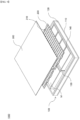
- FIG. 2 is a perspective view of a battery pack 1000 according to a first embodiment of the present invention.
- the battery pack 1000 of the present invention as shown in FIG. 2 includes a pack case 100, a top cover 300, and a screen cover 200.
- the pack case 100 serves to provide a space in which the battery module M is seated and encloses and protects the bottom and sides of the battery module M seated therein.
- the pack case 100 comprises a base plate 110 supporting the bottom of the battery module M, and side wall 120 coupled along an edge of the base plate 110 to support the sides of the battery module M.
- the pack case 100 may further comprise a main separation wall 130 coupled across the center of the base plate 110.
- the main separation wall 130 divides the internal space of the pack case 100 in half and separates into two large spaces.
- various measuring wires, busbars, and the like may be inserted.
- the pack case 100 includes a pair of module areas divided by the main separation wall 130, wherein each module area may contain one or more battery modules M.
- the pack case 100 may further comprise a sub separation wall 140, which is coupled at both ends to the main separation wall 130 and the side wall 120, respectively.
- the sub separation wall 140 serve to re-divide the module area formed on one side of the main separation wall 130, separating each battery module M from the other.
- the sub separation wall 140 are spaced apart at predetermined intervals along the length direction of the main separation wall 130 on both sides of the main separation wall 130 and are coupled to the base plate 110.
- the top cover 300 is coupled to the pack case 100, and serves to cover the top of the battery module M seated in the pack case 100 to protect from external shocks etc. More specifically, the top cover 300 is coupled to the side wall 120 included in the pack case 100 to enclose and protect all of the top of the battery module M therein.
- the screen cover 200 is interposed between the pack case 100 and the top cover 300 and covers the top of each battery module M at the bottom of the top cover 300.
- FIG. 3 is a top view of the battery pack 1000 without the upper cover 300
- FIG. 4 is a cross-sectional view of a part of the battery pack 1000 of FIG. 3 between the sub separation wall 140.
- the screen cover 200 as shown in FIGS. 2 and 3 is characterized in that it includes a through hole 210 that is open to expose the top of the battery module M to the outside.
- the screen cover 200 including the through hole 210 is coupled to the pack case 100 to cover the top of the plurality of battery modules M seated in the pack case 100.
- the screen cover 200 of the present invention serves to prevent flames from spreading to the outside when a fire occurs in the plurality of battery modules M accommodated therein.
- the flame is blocked by the screen cover 200 and cannot spread to the outside, but only moves D 1 along the bottom surface of the screen cover 200, and the gas moves D2 through the through hole 210 and is discharged to the outside.
- the through hole 210 formed in the screen cover 200, as shown in FIG. 4 may serve as a passageway for high temperature gases generated with a fire to discharge but may prevent flames from escaping.
- the screen cover 200 may prevent fire from spreading to the entire battery pack 1000 by preventing flames from directly contacting the top cover 300.
- the screen cover 200 may be directly exposed to the flame generated by the battery module M in thermal runaway condition, and should be able to withstand high temperatures of heat in the exposed state. Therefore, the screen cover 200 preferably comprises a material that is resistant to high temperatures of heat and flame. In other words, the screen cover 200 preferably comprises a flame-resistant material.
- the screen cover 200 may be coupled to the side wall 120 of the pack case 100, same as the top cover 300, or may be coupled to the main separation wall 130 and sub separation wall 140.
- the sides of the screen cover 200 may comprise protrusion part 220 projecting sideways along the perimeter and groove part 230 formed between the protrusion part 220.
- the top of the side wall 120 of the pack case 100 may be structured to engage the protrusion part 220 and groove part 230 of the screen cover 200, and the screen cover 200 may be secured to the pack case 100 with the protrusion part 220 and groove part 230 engaging and coupled to the side wall 120.
- the size and number of the through hole 210 may be designed to vary according to the size and number of the battery module M accommodated in the battery pack 1000.
- the through holes 210 is preferably limited to a size such that flames generated by the battery modules M are not exposed to the outside through the through hole 210.
- the screen cover 200 may include a plurality of through holes 210, and the plurality of through holes 210 may be formed at predetermined intervals spaced apart.
- the through holes 210 are formed along a transverse axis and a vertical axis of the screen cover 200.
- the battery pack 1000 of the present invention is capable of preventing the flame from spreading upward through a screen cover 200 interposed between the upper cover 300 and the battery module M.
- the screen cover 200 prevents the flame from spreading upward.
- the screen cover 200 can selectively discharge high temperature gases through the through hole 210.
- the battery pack 1000 of the present invention may also include a plurality of screen covers 200.
- a plurality of stacked screen covers 200 may not only prevent flames from the bottom, but also delay the transfer of high temperature heat to the top cover 300.
- FIG. 5 illustrates a first modified example of the screen cover 200, in which a plurality of screen covers 200 are stacked
- FIG. 6 illustrates a second modified example of the screen cover 200, in which a plurality of screen covers 200 are stacked.
- FIG. 5 illustrates a plurality of screen covers 200 stacked together with through holes 210 disposed in the same location, so that the through holes 210 allow for the discharge of gases but prevent the discharge of flames.
- FIG. 6 shows a stacked form of a plurality of screen covers 200 in which the through holes 210 are disposed in non-uniform positions, that is, the through holes 210 included in any one of the plurality of screen covers 200 are disposed in positions that are obstructed by other screen covers 200.
- the screen cover 200 stacked in the form shown in FIG. 6 has the advantage that the discharge of gas may not be smooth, but the discharge of flame can be effectively prevented.
- the through hole 210 may be circular shape as shown, but is not limited to, and the through hole 210 may be formed in a circular shape as shown, or may be formed in a polygonal shape.
- FIG. 7 is a third modified example of the screen cover 200, in which a rectangular through hole 210 is formed.
- the through hole 210 may be formed in a point shape, such as circular or polygonal shape, or may be formed in the slit shape.
- FIG. 8 shows a fourth modified example of the screen cover 200, in which a slit-shaped through hole 210 is formed.
- the through hole 210 in the form shown in FIG. 8 extends along a transverse or vertical axis of the screen cover 200.
- the slit-shaped through hole 210 as described above has a larger area opened, but it is possible to prevent flames by adjusting the width of the through hole 210.
- the screen cover 200 may further comprise a rupture member (not shown) coupled to an inner circumferential surface of the through hole 210 to block the through hole 210.
- These rupture members may be ruptured by high temperatures of heat or gases under high pressure generated by thermal runaway of the battery module M.
- the rupture member which is usually coupled to the through hole 210 and serves to ensure that the battery module M accommodated therein is sealed, may be melted by the high temperature heat generated by the thermal runaway of the battery module M.
- the through hole 210 may be opened as the rupture member is melted by the high temperature heat generated in the module area.
- the rupture member may comprise a thermoplastic material that is readily melted by high temperatures of heat.
- the rupture member may be destroyed by a high-pressure gas generated by the thermal runaway of the battery module M. That is, the through hole 210 may be opened by the destruction of the rupture member by a high-pressure gas generated in the module area.
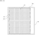
- FIG. 9 is a perspective view of a battery pack 1000 according to a second embodiment of the present invention
- FIG. 10 is a plan view of the battery pack 1000 of FIG. 9 with the top cover 300 removed.
- the battery pack 1000 of the present invention includes a pack case 100, a top cover 300, and a screen cover 200, as shown in FIG. 9 above.
- the screen cover 200 is coupled to the pack case 100 to cover at least one of a pair of module areas divided by the main separation wall 130.
- the battery pack 1000 according to a second embodiment of the present invention is characterized in that the screen cover 200 can be coupled in pairs to either side of the main separation wall 130.
- the screen covers 200 separated by the main separation wall 130 are not connected to each other, so heat transfer through conduction between them is not possible. Therefore, even if a thermal runaway occurs in the battery module M accommodated on one side of the main separation wall 130, and the screen cover 200 covering the top of the battery module M is heated by the high temperature, the heat is not transferred to the other screen cover 200 disposed on the other side of the main separation wall 130.
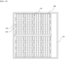
- FIG. 11 is a perspective view of a battery pack 1000 according to a third embodiment of the present invention
- FIG. 12 is a plan view of the battery pack 1000 of FIG. 11 with the top cover 300 removed.
- the battery pack 1000 of the present invention includes a pack case 100, a top cover 300, and a screen cover 200, as shown in FIG. 11 .
- the screen cover 200 is coupled to the pack case 100 to cover at least one of a plurality of module areas formed by the main separation wall 130 and sub separation wall 140.
- the battery pack 1000 according to a third embodiment of the present invention, wherein the screen cover 200 is coupled to cover a module area between a pair of sub separation wall 140 disposed at predetermined intervals on either side of the main separation wall 130.
- Each of the module areas may be covered by one screen cover 200, wherein a pair of screen covers 200 disposed adjacent to each other may be engaged by the protrusion part 220 and the groove part 230 engaging each other.
Landscapes
- Chemical & Material Sciences (AREA)
- Chemical Kinetics & Catalysis (AREA)
- Electrochemistry (AREA)
- General Chemical & Material Sciences (AREA)
- Battery Mounting, Suspending (AREA)
- Gas Exhaust Devices For Batteries (AREA)
- Engineering & Computer Science (AREA)
- Aviation & Aerospace Engineering (AREA)
Abstract
Description
- The present invention relates to a battery pack, characterized in that when a flame with high temperature gases occurs in any one of a plurality of battery modules accommodated therein, a screen cover is applied which is capable of extinguishing the flame so that the flame is not directly exposed to the outside.
- This application claims the benefit of priority based on
Korean Patent Application No. 10-2022-0136062, filed on October 21, 2022 - One of the most important problems with lithium secondary batteries is securing the safety, as there is a risk of explosion and fire, etc. due to heat generation. The internal temperature of the secondary battery increases rapidly due to heat generation, and the rapid increase in temperature can cause thermal runaway phenomenon, which can lead to an explosion of the secondary battery, and can also spread to adjacent secondary batteries, causing great damage to the battery pack.
- In order to eliminate such risks, control means are provided to monitor and control the voltage, current, etc. of a battery pack, or means are provided to extinguish a fire from the outside when a fire occurs in a battery pack, but there is a problem that such means alone cannot provide an initial rapid and active response to a fire occurring in a battery pack.
-
FIG. 1 is a perspective view of aconventional battery pack 10, including a pack case and a battery module M accommodated in an inner space of the pack case. - In a
battery pack 10 of the structure described above, when thermal runaway occurs in any of the battery modules M accommodated therein, flames generated by the battery modules M may be discharged to the outside through the top.Most battery packs 10 may further include a top cover etc. that is coupled to the pack case to cover the top of the battery modules M, but there is a significant risk that the top cover may also be damaged by exposure to the flame. - (Patent Document 1)
Korean Patent Publication No. 10-2022-0004854 - Accordingly, the present invention was conceived to solve the above problems, and an object is to provide a battery pack capable of preventing the flame generated with the thermal runaway from being directly exposed to the outside, even if a thermal runaway phenomenon occurs in the battery module accommodated therein.
- Other objects and advantages of the present invention will be understood from the following description and will become more apparent with reference to embodiments of the present invention. Also, it will be readily apparent that the objects and advantages of the present invention may be realized by the means and combinations thereof disclosed in the patent claims.
- According to the present invention, a battery pack accommodating a battery module includes: a pack case providing a space in which the battery module is seated; the top cover coupled to the pack case to cover the top of the battery module seated in the pack case; and a screen cover interposed between the pack case and the top cover,
a battery pack characterized in that the screen cover comprises a through hole opened to expose a top of the battery module to the outside. - The screen cover may include a plurality of through holes, and the through holes may be formed at predetermined intervals spaced along a transverse axis and a vertical axis of the screen cover.
- The through holes may be formed in at least one of a circular and a polygon shape.
- The pack case including: a base plate supporting the bottom of the battery module; a main separation wall coupled across a center of the base plate; and a side wall coupled along an edge of the base plate; wherein the pack case includes a pair of module areas divided by the main separation wall, and the screen cover may be coupled to the pack case to cover at least one of the module areas among the pair of module areas.
- The pack case including: a base plate supporting the bottom of the battery module; a main separation wall coupled across a center of the base plate; a side wall coupled along an edge of the base plate; and a sub separation wall coupled at both ends with the main separation wall and the side wall, respectively, and coupled to the base plate at predetermined intervals spaced along a length direction of the main separation wall; wherein the pack case includes a plurality of module areas divided and formed by the main separation wall and the sub separation wall, and the screen cover may be coupled to the pack case to cover at least one of the module areas among the plurality of module areas.
- The sides of the screen cover comprise laterally projecting protrusion parts and groove parts formed between the protrusion parts, and a pair of screen covers disposed adjacent to each other may be coupled by engaging the protrusion parts and groove parts with each other.
- The screen cover may include a flame-resistant material.
- The screen cover may further include a rupture member coupled to an inner circumferential surface of the through hole to block the through hole.
- The rupture member may include a thermoplastic material, and the through hole may be opened as the rupture member is melted by the high temperature heat generated in the module area.
- The rupture member is coupled to the through hole to be destroyed when a certain pressure is applied, and the through hole may be opened by the destruction of the rupture member by high pressure gas generated in the module area.
- A plurality of screen covers may be stacked and interposed between the top cover and the pack case.
- The plurality of screen covers may be disposed with each of the through holes in the same position.
- Any one of the plurality of screen covers may be disposed in a position where the through hole is obstructed by another screen cover.
- The through hole may be formed in a slit form.
- According to the present invention, even if a thermal runaway occurs in the battery module accommodated inside, the stability of a battery pack can be improved by preventing the phenomenon that a flame generated simultaneously with the thermal runaway occurs to the outside.
-
-
FIG. 1 is a perspective view of a conventional battery pack. -
FIG. 2 is a perspective view of a battery pack according to a first embodiment of the present invention. -
FIG. 3 is a top view of the battery pack, without the top cover. -
FIG. 4 is a cross-sectional view of a portion of the battery pack ofFIG. 3 between the sub separation walls. -
FIG. 5 illustrates a first modified example of the screen cover. -
FIG. 6 illustrates a second modified example of the screen cover. -
FIG. 7 illustrates a third modified example of the screen cover. -
FIG. 8 illustrates a fourth modified example of the screen cover. -
FIG. 9 is a perspective view of a battery pack according to a second embodiment of the present invention. -
FIG. 10 is a top view of the battery pack ofFIG. 9 with the top cover removed. -
FIG. 11 is a perspective view of a battery pack according to a third embodiment of the present invention. -
FIG. 12 is a top view of the battery pack ofFIG. 11 with the top cover removed. - Hereinafter, the present invention will be described in detail with reference to the drawings. Prior to this, terms and words used in the present specification and claims should not be construed as limited to general or dictionary terms and should be interpreted with the meaning and concept in accordance with the technical idea of the present invention based on the principle that the inventors have appropriately defined the concepts of terms in order to explain the invention in the best way.
- Accordingly, it is to be understood that the embodiments described herein, and the configurations illustrated in the drawings are only the most preferred embodiments of the present invention and do not represent all of the technical ideas of the present invention, so it should be understood that other equivalents and modifications could be made thereto without departing from the spirit and scope of the disclosure.
- In addition, detailed descriptions of well-known functions and constructions may be omitted for clarity and conciseness.
- The embodiments of the present invention are provided to illustrate the present invention more completely to those of ordinary skill in the art, and the shapes and sizes of the components in the drawings may be exaggerated, omitted, or shown schematically for clarity. Therefore, the size or proportions of each component are not necessarily indicative of actual size or proportions.
- The present invention relates to a battery pack, characterized in that when a flame with high temperature gases occurs in any one of a plurality of battery modules accommodated therein, a screen cover is applied which is capable of extinguishing the flame so that the flame is not directly exposed to the outside.
-
FIG. 3 to FIG. 6 relate to a battery pack according to a first embodiment of the present invention,FIG. 9 to FIG. 10 relate to a battery pack according to a second embodiment of the present invention, andFIG. 11 to FIG. 12 relate to a battery pack according to a third embodiment of the present invention. - Hereinafter, the battery pack of the present invention according to each embodiment will be described with reference to the accompanying drawings.
-
FIG. 2 is a perspective view of abattery pack 1000 according to a first embodiment of the present invention. - The
battery pack 1000 of the present invention as shown inFIG. 2 includes apack case 100, atop cover 300, and ascreen cover 200. - The
pack case 100 serves to provide a space in which the battery module M is seated and encloses and protects the bottom and sides of the battery module M seated therein. - The
pack case 100 comprises abase plate 110 supporting the bottom of the battery module M, andside wall 120 coupled along an edge of thebase plate 110 to support the sides of the battery module M. - The
pack case 100 may further comprise amain separation wall 130 coupled across the center of thebase plate 110. - The
main separation wall 130 divides the internal space of thepack case 100 in half and separates into two large spaces. - Within the
main separation wall 130, various measuring wires, busbars, and the like may be inserted. - The
pack case 100 includes a pair of module areas divided by themain separation wall 130, wherein each module area may contain one or more battery modules M. - The
pack case 100 may further comprise asub separation wall 140, which is coupled at both ends to themain separation wall 130 and theside wall 120, respectively. - The
sub separation wall 140 serve to re-divide the module area formed on one side of themain separation wall 130, separating each battery module M from the other. - The
sub separation wall 140 are spaced apart at predetermined intervals along the length direction of themain separation wall 130 on both sides of themain separation wall 130 and are coupled to thebase plate 110. - The
top cover 300 is coupled to thepack case 100, and serves to cover the top of the battery module M seated in thepack case 100 to protect from external shocks etc. More specifically, thetop cover 300 is coupled to theside wall 120 included in thepack case 100 to enclose and protect all of the top of the battery module M therein. - The
screen cover 200 is interposed between thepack case 100 and thetop cover 300 and covers the top of each battery module M at the bottom of thetop cover 300. -
FIG. 3 is a top view of thebattery pack 1000 without theupper cover 300, andFIG. 4 is a cross-sectional view of a part of thebattery pack 1000 ofFIG. 3 between thesub separation wall 140. - The
screen cover 200, as shown inFIGS. 2 and3 is characterized in that it includes a throughhole 210 that is open to expose the top of the battery module M to the outside. - The
screen cover 200 including the throughhole 210 is coupled to thepack case 100 to cover the top of the plurality of battery modules M seated in thepack case 100. - The
screen cover 200 of the present invention serves to prevent flames from spreading to the outside when a fire occurs in the plurality of battery modules M accommodated therein. - Referring to
FIG. 4 , the flame is blocked by thescreen cover 200 and cannot spread to the outside, but only moves D 1 along the bottom surface of thescreen cover 200, and the gas moves D2 through the throughhole 210 and is discharged to the outside. - The through
hole 210 formed in thescreen cover 200, as shown inFIG. 4 may serve as a passageway for high temperature gases generated with a fire to discharge but may prevent flames from escaping. Thus, thescreen cover 200 may prevent fire from spreading to theentire battery pack 1000 by preventing flames from directly contacting thetop cover 300. - The
screen cover 200 may be directly exposed to the flame generated by the battery module M in thermal runaway condition, and should be able to withstand high temperatures of heat in the exposed state. Therefore, thescreen cover 200 preferably comprises a material that is resistant to high temperatures of heat and flame. In other words, thescreen cover 200 preferably comprises a flame-resistant material. - The
screen cover 200 may be coupled to theside wall 120 of thepack case 100, same as thetop cover 300, or may be coupled to themain separation wall 130 andsub separation wall 140. - The sides of the
screen cover 200 may compriseprotrusion part 220 projecting sideways along the perimeter andgroove part 230 formed between theprotrusion part 220. In this case, the top of theside wall 120 of thepack case 100 may be structured to engage theprotrusion part 220 andgroove part 230 of thescreen cover 200, and thescreen cover 200 may be secured to thepack case 100 with theprotrusion part 220 andgroove part 230 engaging and coupled to theside wall 120. - The size and number of the through
hole 210 may be designed to vary according to the size and number of the battery module M accommodated in thebattery pack 1000. - However, the through
holes 210 is preferably limited to a size such that flames generated by the battery modules M are not exposed to the outside through the throughhole 210. - The
screen cover 200 may include a plurality of throughholes 210, and the plurality of throughholes 210 may be formed at predetermined intervals spaced apart. - The through
holes 210, as shown inFIGS. 2 and3 . are formed along a transverse axis and a vertical axis of thescreen cover 200. - When a fire occurs in the battery module M accommodated in the
battery pack 1000 of the present invention, the flame caused by the fire spreads upwards where thetop cover 300 is located. However, thebattery pack 1000 of the present invention is capable of preventing the flame from spreading upward through ascreen cover 200 interposed between theupper cover 300 and the battery module M. Thescreen cover 200 prevents the flame from spreading upward. Furthermore, thescreen cover 200 can selectively discharge high temperature gases through the throughhole 210. - The
battery pack 1000 of the present invention may also include a plurality of screen covers 200. In other words, a plurality of stacked screen covers 200 may not only prevent flames from the bottom, but also delay the transfer of high temperature heat to thetop cover 300. -
FIG. 5 illustrates a first modified example of thescreen cover 200, in which a plurality of screen covers 200 are stacked, andFIG. 6 illustrates a second modified example of thescreen cover 200, in which a plurality of screen covers 200 are stacked. -
FIG. 5 illustrates a plurality of screen covers 200 stacked together with throughholes 210 disposed in the same location, so that the throughholes 210 allow for the discharge of gases but prevent the discharge of flames. -
FIG. 6 shows a stacked form of a plurality of screen covers 200 in which the throughholes 210 are disposed in non-uniform positions, that is, the throughholes 210 included in any one of the plurality of screen covers 200 are disposed in positions that are obstructed by other screen covers 200. - The
screen cover 200 stacked in the form shown inFIG. 6 has the advantage that the discharge of gas may not be smooth, but the discharge of flame can be effectively prevented. - The through
hole 210 may be circular shape as shown, but is not limited to, and the throughhole 210 may be formed in a circular shape as shown, or may be formed in a polygonal shape. -
FIG. 7 is a third modified example of thescreen cover 200, in which a rectangular throughhole 210 is formed. - The through
hole 210 may be formed in a point shape, such as circular or polygonal shape, or may be formed in the slit shape. -
FIG. 8 shows a fourth modified example of thescreen cover 200, in which a slit-shaped throughhole 210 is formed. The throughhole 210 in the form shown inFIG. 8 extends along a transverse or vertical axis of thescreen cover 200. The slit-shaped throughhole 210 as described above has a larger area opened, but it is possible to prevent flames by adjusting the width of the throughhole 210. - The
screen cover 200 may further comprise a rupture member (not shown) coupled to an inner circumferential surface of the throughhole 210 to block the throughhole 210. - These rupture members may be ruptured by high temperatures of heat or gases under high pressure generated by thermal runaway of the battery module M.
- Specifically, the rupture member, which is usually coupled to the through
hole 210 and serves to ensure that the battery module M accommodated therein is sealed, may be melted by the high temperature heat generated by the thermal runaway of the battery module M. In other words, the throughhole 210 may be opened as the rupture member is melted by the high temperature heat generated in the module area. In this case, the rupture member may comprise a thermoplastic material that is readily melted by high temperatures of heat. - Alternatively, the rupture member may be destroyed by a high-pressure gas generated by the thermal runaway of the battery module M. That is, the through
hole 210 may be opened by the destruction of the rupture member by a high-pressure gas generated in the module area. -
FIG. 9 is a perspective view of abattery pack 1000 according to a second embodiment of the present invention, andFIG. 10 is a plan view of thebattery pack 1000 ofFIG. 9 with thetop cover 300 removed. - The
battery pack 1000 of the present invention includes apack case 100, atop cover 300, and ascreen cover 200, as shown inFIG. 9 above. - The
screen cover 200 is coupled to thepack case 100 to cover at least one of a pair of module areas divided by themain separation wall 130. In other words, thebattery pack 1000 according to a second embodiment of the present invention is characterized in that thescreen cover 200 can be coupled in pairs to either side of themain separation wall 130. - As described above, the screen covers 200 separated by the
main separation wall 130 are not connected to each other, so heat transfer through conduction between them is not possible. Therefore, even if a thermal runaway occurs in the battery module M accommodated on one side of themain separation wall 130, and thescreen cover 200 covering the top of the battery module M is heated by the high temperature, the heat is not transferred to theother screen cover 200 disposed on the other side of themain separation wall 130. -
FIG. 11 is a perspective view of abattery pack 1000 according to a third embodiment of the present invention, andFIG. 12 is a plan view of thebattery pack 1000 ofFIG. 11 with thetop cover 300 removed. - The
battery pack 1000 of the present invention includes apack case 100, atop cover 300, and ascreen cover 200, as shown inFIG. 11 . - The
screen cover 200 is coupled to thepack case 100 to cover at least one of a plurality of module areas formed by themain separation wall 130 andsub separation wall 140. In other words, thebattery pack 1000 according to a third embodiment of the present invention, wherein thescreen cover 200 is coupled to cover a module area between a pair ofsub separation wall 140 disposed at predetermined intervals on either side of themain separation wall 130. - Each of the module areas may be covered by one
screen cover 200, wherein a pair of screen covers 200 disposed adjacent to each other may be engaged by theprotrusion part 220 and thegroove part 230 engaging each other. - When a
single screen cover 200 is coupled to a module area as described above, it is possible to selectively position thescreen cover 200 in only those areas where it is needed, thereby reducing the amount ofscreen cover 200 used to further improve safety while simultaneously improving the energy efficiency of thebattery pack 1000. - Although the invention is shown and described in connection with particular embodiments, it will be readily apparent to those of ordinary skill in the art that various modifications and variations are possible without departing from the spirit and scope of the invention shown in the appended claims.
-
- 10: (prior art) battery pack
- 1000: battery pack
- 100: pack case
- 110: base plate
- 120: side wall
- 130: main separation wall
- 140: sub separation wall
- 200: screen cover
- 210: through hole
- 220: protrusion part
- 230: groove part
- 300: top cover
- M: battery module
- D1: flame movement
- D2: gas movement
Claims (14)
- A battery pack accommodating a battery module comprising:a pack case providing a space in which the battery module is seated;a top cover coupled to the pack case to cover the top of the battery module seated in the pack case; anda screen cover interposed between the pack case and the top cover,and a battery pack characterized in that the screen cover comprises a through hole opened to expose the top of the battery module to the outside.
- The battery pack of claim 1, wherein the screen cover comprises a plurality of through holes, and the through holes are formed at predetermined intervals spaced along a transverse axis and a vertical axis of the screen cover.
- The battery pack of claim 1, wherein the through holes are formed in at least one of a circular and a polygon shape.
- The battery pack of claim 1, wherein the pack case comprising:a base plate supporting the bottom of the battery module;a main separation wall coupled across a center of the base plate; andside walls coupled along an edge of the base plate;wherein the pack case comprises a pair of module areas divided by the main separation wall, and the screen cover is coupled to the pack case to cover at least one of the module areas among the pair of module areas.
- The battery pack of claim 1, wherein the pack case comprising:a base plate supporting the bottom of the battery module;a main separation wall coupled across a center of the base plate;a side wall coupled along an edge of the base plate; anda sub separation wall coupled at both ends with the main separation wall and the side wall, respectively, and coupled to the base plate at predetermined intervals spaced along a length direction of the main separation wall,wherein the pack case comprises a plurality of module areas divided and formed by the main separation wall and the sub separation wall, and the screen cover is coupled to the pack case to cover at least one of the module areas among the plurality of module areas.
- The battery pack of claim 5, wherein the sides of the screen cover comprise laterally projecting protrusion parts and groove parts formed between the protrusion parts,
and a pair of screen covers disposed adjacent to each other is coupled by engaging the protrusion parts and groove parts with each other. - The battery pack of claim 1, wherein the screen cover comprises a flame-resistant material.
- The battery pack of claim 1, wherein the screen cover further comprises a rupture member coupled to an inner circumferential surface of the through hole to block the through hole.
- The battery pack of claim 8, wherein the rupture member comprises a thermoplastic material, and the through hole is opened as the rupture member is melted by the high temperature heat generated in the module area.
- The battery pack of claim 8, wherein the rupture member is coupled to the through hole to be destroyed when a certain pressure is applied, and the through hole is opened by the destruction of the rupture member by high pressure gas generated in the module area .
- The battery pack of claim 1, wherein a plurality of screen covers is stacked and interposed between the top cover and the pack case.
- The battery pack of claim 11, wherein the plurality of screen covers are disposed with each of the through holes in the same position.
- The battery pack of claim 11, wherein any one of the plurality of screen covers are disposed in a position where the through hole is obstructed by another screen cover.
- The battery pack of claim 1, wherein the through hole is formed in a slit form.
Applications Claiming Priority (2)
| Application Number | Priority Date | Filing Date | Title |
|---|---|---|---|
| KR1020220136062A KR102940116B1 (en) | 2022-10-21 | 2022-10-21 | Battery pack |
| PCT/KR2023/016330 WO2024085707A1 (en) | 2022-10-21 | 2023-10-20 | Battery pack |
Publications (2)
| Publication Number | Publication Date |
|---|---|
| EP4478512A1 true EP4478512A1 (en) | 2024-12-18 |
| EP4478512A4 EP4478512A4 (en) | 2025-07-09 |
Family
ID=90738206
Family Applications (1)
| Application Number | Title | Priority Date | Filing Date |
|---|---|---|---|
| EP23880282.1A Pending EP4478512A4 (en) | 2022-10-21 | 2023-10-20 | BATTERY PACK |
Country Status (6)
| Country | Link |
|---|---|
| US (1) | US20250273812A1 (en) |
| EP (1) | EP4478512A4 (en) |
| JP (1) | JP7820026B2 (en) |
| KR (1) | KR102940116B1 (en) |
| CN (1) | CN118872137A (en) |
| WO (1) | WO2024085707A1 (en) |
Families Citing this family (2)
| Publication number | Priority date | Publication date | Assignee | Title |
|---|---|---|---|---|
| KR20260043266A (en) * | 2024-09-24 | 2026-03-31 | 주식회사 엘지에너지솔루션 | Battery pack |
| WO2026095482A1 (en) * | 2024-11-04 | 2026-05-07 | 주식회사 엘지에너지솔루션 | Battery assembly |
Family Cites Families (13)
| Publication number | Priority date | Publication date | Assignee | Title |
|---|---|---|---|---|
| JP5466906B2 (en) * | 2009-09-18 | 2014-04-09 | パナソニック株式会社 | Battery module |
| JP5709908B2 (en) * | 2013-01-11 | 2015-04-30 | 三菱重工業株式会社 | Battery pack cover, battery module, and battery system |
| TWI628831B (en) * | 2013-08-30 | 2018-07-01 | 睿能創意公司 | Portable electrical energy storage device with thermal runaway mitigation |
| CN109873104B (en) * | 2018-12-13 | 2024-04-16 | 宁德时代新能源科技股份有限公司 | Battery module |
| CN110828747A (en) * | 2019-11-15 | 2020-02-21 | 爱驰汽车有限公司 | Thermal protection system for power battery |
| CN211320177U (en) * | 2020-01-22 | 2020-08-21 | 荣盛盟固利新能源科技有限公司 | Soft package battery system without module |
| KR102942238B1 (en) | 2020-07-02 | 2026-03-23 | 주식회사 엘지에너지솔루션 | Battery pack comprising fire extinguishing apparatus |
| CN213124586U (en) * | 2020-07-13 | 2021-05-04 | 远景动力技术(江苏)有限公司 | A battery pack accommodating device |
| KR102927031B1 (en) * | 2021-01-04 | 2026-02-11 | 한화에어로스페이스 주식회사 | Battery pack |
| KR102329179B1 (en) | 2021-03-30 | 2021-11-19 | 쿠팡 주식회사 | Item sales information processing method and electronic device |
| HUE072871T2 (en) * | 2021-03-31 | 2025-12-28 | Contemporary Amperex Tech | Case of battery and battery |
| CN215816017U (en) * | 2021-05-27 | 2022-02-11 | 肇庆小鹏汽车有限公司 | Power battery and vehicle |
| KR20240024684A (en) * | 2022-08-17 | 2024-02-26 | 주식회사 엘지에너지솔루션 | Battery pack having double top cover with venting gas passage |
-
2022
- 2022-10-21 KR KR1020220136062A patent/KR102940116B1/en active Active
-
2023
- 2023-10-20 JP JP2024554954A patent/JP7820026B2/en active Active
- 2023-10-20 US US18/847,217 patent/US20250273812A1/en active Pending
- 2023-10-20 EP EP23880282.1A patent/EP4478512A4/en active Pending
- 2023-10-20 CN CN202380027249.9A patent/CN118872137A/en active Pending
- 2023-10-20 WO PCT/KR2023/016330 patent/WO2024085707A1/en not_active Ceased
Also Published As
| Publication number | Publication date |
|---|---|
| CN118872137A (en) | 2024-10-29 |
| JP7820026B2 (en) | 2026-02-25 |
| KR20240055982A (en) | 2024-04-30 |
| US20250273812A1 (en) | 2025-08-28 |
| EP4478512A4 (en) | 2025-07-09 |
| KR102940116B1 (en) | 2026-03-16 |
| JP2025511535A (en) | 2025-04-16 |
| WO2024085707A1 (en) | 2024-04-25 |
Similar Documents
| Publication | Publication Date | Title |
|---|---|---|
| US20250273812A1 (en) | Battery pack and vehicle | |
| KR20230131112A (en) | Battery module and battery pack including same | |
| KR102880677B1 (en) | Battery module and, battery pack and vehicle including same | |
| ES2959765T3 (en) | COVER ASSEMBLY INCLUDING GUIDING ELEMENT TO PREVENT ESCAPE FROM THE SAFETY HOLE | |
| KR20240013826A (en) | Secondary battery having venting part | |
| US20250158219A1 (en) | Safety reinforced battery module | |
| JP7819231B2 (en) | Battery module and battery pack including the same | |
| KR20240097754A (en) | Battery pack with improved safety | |
| KR102957718B1 (en) | Battery pack | |
| EP4604298A1 (en) | Battery pack | |
| EP4376155A1 (en) | Battery pack with improved safety | |
| CN120153515A (en) | Battery pack with improved fire resistance | |
| KR20240083794A (en) | battery module and battery pack including the same | |
| KR102835253B1 (en) | Battery module | |
| EP4651288A1 (en) | Battery pack and battery device including same | |
| US20250260123A1 (en) | Battery Pack | |
| KR20260011897A (en) | Battery pack and vehicle including the same | |
| KR102805378B1 (en) | Rechargeable battery module | |
| EP4261999B1 (en) | Battery module having improved airtightness and heat resistance of module case | |
| KR20240102773A (en) | Battery module and Battery Pack including the same | |
| KR20230162168A (en) | Secondary battery having venting device | |
| EP4668454A1 (en) | Battery pack and vehicle including same | |
| EP4607680A1 (en) | Battery pack | |
| KR20250175647A (en) | Battery pack and vehicle including the same | |
| KR20250110621A (en) | Cylindrical secondary battery |
Legal Events
| Date | Code | Title | Description |
|---|---|---|---|
| STAA | Information on the status of an ep patent application or granted ep patent |
Free format text: STATUS: THE INTERNATIONAL PUBLICATION HAS BEEN MADE |
|
| PUAI | Public reference made under article 153(3) epc to a published international application that has entered the european phase |
Free format text: ORIGINAL CODE: 0009012 |
|
| STAA | Information on the status of an ep patent application or granted ep patent |
Free format text: STATUS: REQUEST FOR EXAMINATION WAS MADE |
|
| 17P | Request for examination filed |
Effective date: 20240913 |
|
| AK | Designated contracting states |
Kind code of ref document: A1 Designated state(s): AL AT BE BG CH CY CZ DE DK EE ES FI FR GB GR HR HU IE IS IT LI LT LU LV MC ME MK MT NL NO PL PT RO RS SE SI SK SM TR |
|
| A4 | Supplementary search report drawn up and despatched |
Effective date: 20250605 |
|
| RIC1 | Information provided on ipc code assigned before grant |
Ipc: H01M 50/289 20210101ALI20250530BHEP Ipc: H01M 50/24 20210101ALI20250530BHEP Ipc: H01M 50/375 20210101ALI20250530BHEP Ipc: H01M 50/342 20210101ALI20250530BHEP Ipc: H01M 50/30 20210101AFI20250530BHEP |
|
| STAA | Information on the status of an ep patent application or granted ep patent |
Free format text: STATUS: EXAMINATION IS IN PROGRESS |
|
| 17Q | First examination report despatched |
Effective date: 20251031 |
|
| DAV | Request for validation of the european patent (deleted) | ||
| DAX | Request for extension of the european patent (deleted) |