EP4478502A1 - Battery and electrical device - Google Patents
Battery and electrical device Download PDFInfo
- Publication number
- EP4478502A1 EP4478502A1 EP22961811.1A EP22961811A EP4478502A1 EP 4478502 A1 EP4478502 A1 EP 4478502A1 EP 22961811 A EP22961811 A EP 22961811A EP 4478502 A1 EP4478502 A1 EP 4478502A1
- Authority
- EP
- European Patent Office
- Prior art keywords
- battery
- battery cells
- thermal conductive
- battery cell
- conductive member
- Prior art date
- Legal status (The legal status is an assumption and is not a legal conclusion. Google has not performed a legal analysis and makes no representation as to the accuracy of the status listed.)
- Pending
Links
Images









Classifications
-
- H—ELECTRICITY
- H01—ELECTRIC ELEMENTS
- H01M—PROCESSES OR MEANS, e.g. BATTERIES, FOR THE DIRECT CONVERSION OF CHEMICAL ENERGY INTO ELECTRICAL ENERGY
- H01M50/00—Constructional details or processes of manufacture of the non-active parts of electrochemical cells other than fuel cells, e.g. hybrid cells
- H01M50/20—Mountings; Secondary casings or frames; Racks, modules or packs; Suspension devices; Shock absorbers; Transport or carrying devices; Holders
- H01M50/204—Racks, modules or packs for multiple batteries or multiple cells
- H01M50/207—Racks, modules or packs for multiple batteries or multiple cells characterised by their shape
- H01M50/209—Racks, modules or packs for multiple batteries or multiple cells characterised by their shape adapted for prismatic or rectangular cells
-
- H—ELECTRICITY
- H01—ELECTRIC ELEMENTS
- H01M—PROCESSES OR MEANS, e.g. BATTERIES, FOR THE DIRECT CONVERSION OF CHEMICAL ENERGY INTO ELECTRICAL ENERGY
- H01M50/00—Constructional details or processes of manufacture of the non-active parts of electrochemical cells other than fuel cells, e.g. hybrid cells
- H01M50/20—Mountings; Secondary casings or frames; Racks, modules or packs; Suspension devices; Shock absorbers; Transport or carrying devices; Holders
- H01M50/204—Racks, modules or packs for multiple batteries or multiple cells
-
- H—ELECTRICITY
- H01—ELECTRIC ELEMENTS
- H01M—PROCESSES OR MEANS, e.g. BATTERIES, FOR THE DIRECT CONVERSION OF CHEMICAL ENERGY INTO ELECTRICAL ENERGY
- H01M10/00—Secondary cells; Manufacture thereof
- H01M10/60—Heating or cooling; Temperature control
- H01M10/61—Types of temperature control
- H01M10/613—Cooling or keeping cold
-
- H—ELECTRICITY
- H01—ELECTRIC ELEMENTS
- H01M—PROCESSES OR MEANS, e.g. BATTERIES, FOR THE DIRECT CONVERSION OF CHEMICAL ENERGY INTO ELECTRICAL ENERGY
- H01M10/00—Secondary cells; Manufacture thereof
- H01M10/60—Heating or cooling; Temperature control
- H01M10/62—Heating or cooling; Temperature control specially adapted for specific applications
- H01M10/625—Vehicles
-
- H—ELECTRICITY
- H01—ELECTRIC ELEMENTS
- H01M—PROCESSES OR MEANS, e.g. BATTERIES, FOR THE DIRECT CONVERSION OF CHEMICAL ENERGY INTO ELECTRICAL ENERGY
- H01M10/00—Secondary cells; Manufacture thereof
- H01M10/60—Heating or cooling; Temperature control
- H01M10/64—Heating or cooling; Temperature control characterised by the shape of the cells
- H01M10/643—Cylindrical cells
-
- H—ELECTRICITY
- H01—ELECTRIC ELEMENTS
- H01M—PROCESSES OR MEANS, e.g. BATTERIES, FOR THE DIRECT CONVERSION OF CHEMICAL ENERGY INTO ELECTRICAL ENERGY
- H01M10/00—Secondary cells; Manufacture thereof
- H01M10/60—Heating or cooling; Temperature control
- H01M10/64—Heating or cooling; Temperature control characterised by the shape of the cells
- H01M10/647—Prismatic or flat cells, e.g. pouch cells
-
- H—ELECTRICITY
- H01—ELECTRIC ELEMENTS
- H01M—PROCESSES OR MEANS, e.g. BATTERIES, FOR THE DIRECT CONVERSION OF CHEMICAL ENERGY INTO ELECTRICAL ENERGY
- H01M10/00—Secondary cells; Manufacture thereof
- H01M10/60—Heating or cooling; Temperature control
- H01M10/65—Means for temperature control structurally associated with the cells
- H01M10/655—Solid structures for heat exchange or heat conduction
-
- H—ELECTRICITY
- H01—ELECTRIC ELEMENTS
- H01M—PROCESSES OR MEANS, e.g. BATTERIES, FOR THE DIRECT CONVERSION OF CHEMICAL ENERGY INTO ELECTRICAL ENERGY
- H01M10/00—Secondary cells; Manufacture thereof
- H01M10/60—Heating or cooling; Temperature control
- H01M10/65—Means for temperature control structurally associated with the cells
- H01M10/655—Solid structures for heat exchange or heat conduction
- H01M10/6556—Solid parts with flow channel passages or pipes for heat exchange
- H01M10/6557—Solid parts with flow channel passages or pipes for heat exchange arranged between the cells
-
- H—ELECTRICITY
- H01—ELECTRIC ELEMENTS
- H01M—PROCESSES OR MEANS, e.g. BATTERIES, FOR THE DIRECT CONVERSION OF CHEMICAL ENERGY INTO ELECTRICAL ENERGY
- H01M50/00—Constructional details or processes of manufacture of the non-active parts of electrochemical cells other than fuel cells, e.g. hybrid cells
- H01M50/10—Primary casings; Jackets or wrappings
- H01M50/102—Primary casings; Jackets or wrappings characterised by their shape or physical structure
- H01M50/107—Primary casings; Jackets or wrappings characterised by their shape or physical structure having curved cross-section, e.g. round or elliptic
-
- H—ELECTRICITY
- H01—ELECTRIC ELEMENTS
- H01M—PROCESSES OR MEANS, e.g. BATTERIES, FOR THE DIRECT CONVERSION OF CHEMICAL ENERGY INTO ELECTRICAL ENERGY
- H01M50/00—Constructional details or processes of manufacture of the non-active parts of electrochemical cells other than fuel cells, e.g. hybrid cells
- H01M50/20—Mountings; Secondary casings or frames; Racks, modules or packs; Suspension devices; Shock absorbers; Transport or carrying devices; Holders
- H01M50/204—Racks, modules or packs for multiple batteries or multiple cells
- H01M50/207—Racks, modules or packs for multiple batteries or multiple cells characterised by their shape
- H01M50/211—Racks, modules or packs for multiple batteries or multiple cells characterised by their shape adapted for pouch cells
-
- H—ELECTRICITY
- H01—ELECTRIC ELEMENTS
- H01M—PROCESSES OR MEANS, e.g. BATTERIES, FOR THE DIRECT CONVERSION OF CHEMICAL ENERGY INTO ELECTRICAL ENERGY
- H01M50/00—Constructional details or processes of manufacture of the non-active parts of electrochemical cells other than fuel cells, e.g. hybrid cells
- H01M50/20—Mountings; Secondary casings or frames; Racks, modules or packs; Suspension devices; Shock absorbers; Transport or carrying devices; Holders
- H01M50/204—Racks, modules or packs for multiple batteries or multiple cells
- H01M50/207—Racks, modules or packs for multiple batteries or multiple cells characterised by their shape
- H01M50/213—Racks, modules or packs for multiple batteries or multiple cells characterised by their shape adapted for cells having curved cross-section, e.g. round or elliptic
-
- H—ELECTRICITY
- H01—ELECTRIC ELEMENTS
- H01M—PROCESSES OR MEANS, e.g. BATTERIES, FOR THE DIRECT CONVERSION OF CHEMICAL ENERGY INTO ELECTRICAL ENERGY
- H01M50/00—Constructional details or processes of manufacture of the non-active parts of electrochemical cells other than fuel cells, e.g. hybrid cells
- H01M50/20—Mountings; Secondary casings or frames; Racks, modules or packs; Suspension devices; Shock absorbers; Transport or carrying devices; Holders
- H01M50/249—Mountings; Secondary casings or frames; Racks, modules or packs; Suspension devices; Shock absorbers; Transport or carrying devices; Holders specially adapted for aircraft or vehicles, e.g. cars or trains
-
- H—ELECTRICITY
- H01—ELECTRIC ELEMENTS
- H01M—PROCESSES OR MEANS, e.g. BATTERIES, FOR THE DIRECT CONVERSION OF CHEMICAL ENERGY INTO ELECTRICAL ENERGY
- H01M50/00—Constructional details or processes of manufacture of the non-active parts of electrochemical cells other than fuel cells, e.g. hybrid cells
- H01M50/20—Mountings; Secondary casings or frames; Racks, modules or packs; Suspension devices; Shock absorbers; Transport or carrying devices; Holders
- H01M50/262—Mountings; Secondary casings or frames; Racks, modules or packs; Suspension devices; Shock absorbers; Transport or carrying devices; Holders with fastening means, e.g. locks
- H01M50/264—Mountings; Secondary casings or frames; Racks, modules or packs; Suspension devices; Shock absorbers; Transport or carrying devices; Holders with fastening means, e.g. locks for cells or batteries, e.g. straps, tie rods or peripheral frames
-
- H—ELECTRICITY
- H01—ELECTRIC ELEMENTS
- H01M—PROCESSES OR MEANS, e.g. BATTERIES, FOR THE DIRECT CONVERSION OF CHEMICAL ENERGY INTO ELECTRICAL ENERGY
- H01M50/00—Constructional details or processes of manufacture of the non-active parts of electrochemical cells other than fuel cells, e.g. hybrid cells
- H01M50/20—Mountings; Secondary casings or frames; Racks, modules or packs; Suspension devices; Shock absorbers; Transport or carrying devices; Holders
- H01M50/289—Mountings; Secondary casings or frames; Racks, modules or packs; Suspension devices; Shock absorbers; Transport or carrying devices; Holders characterised by spacing elements or positioning means within frames, racks or packs
-
- H—ELECTRICITY
- H01—ELECTRIC ELEMENTS
- H01M—PROCESSES OR MEANS, e.g. BATTERIES, FOR THE DIRECT CONVERSION OF CHEMICAL ENERGY INTO ELECTRICAL ENERGY
- H01M50/00—Constructional details or processes of manufacture of the non-active parts of electrochemical cells other than fuel cells, e.g. hybrid cells
- H01M50/20—Mountings; Secondary casings or frames; Racks, modules or packs; Suspension devices; Shock absorbers; Transport or carrying devices; Holders
- H01M50/289—Mountings; Secondary casings or frames; Racks, modules or packs; Suspension devices; Shock absorbers; Transport or carrying devices; Holders characterised by spacing elements or positioning means within frames, racks or packs
- H01M50/291—Mountings; Secondary casings or frames; Racks, modules or packs; Suspension devices; Shock absorbers; Transport or carrying devices; Holders characterised by spacing elements or positioning means within frames, racks or packs characterised by their shape
-
- H—ELECTRICITY
- H01—ELECTRIC ELEMENTS
- H01M—PROCESSES OR MEANS, e.g. BATTERIES, FOR THE DIRECT CONVERSION OF CHEMICAL ENERGY INTO ELECTRICAL ENERGY
- H01M50/00—Constructional details or processes of manufacture of the non-active parts of electrochemical cells other than fuel cells, e.g. hybrid cells
- H01M50/50—Current conducting connections for cells or batteries
- H01M50/531—Electrode connections inside a battery casing
-
- H—ELECTRICITY
- H01—ELECTRIC ELEMENTS
- H01M—PROCESSES OR MEANS, e.g. BATTERIES, FOR THE DIRECT CONVERSION OF CHEMICAL ENERGY INTO ELECTRICAL ENERGY
- H01M50/00—Constructional details or processes of manufacture of the non-active parts of electrochemical cells other than fuel cells, e.g. hybrid cells
- H01M50/50—Current conducting connections for cells or batteries
- H01M50/531—Electrode connections inside a battery casing
- H01M50/533—Electrode connections inside a battery casing characterised by the shape of the leads or tabs
-
- H—ELECTRICITY
- H01—ELECTRIC ELEMENTS
- H01M—PROCESSES OR MEANS, e.g. BATTERIES, FOR THE DIRECT CONVERSION OF CHEMICAL ENERGY INTO ELECTRICAL ENERGY
- H01M2220/00—Batteries for particular applications
- H01M2220/20—Batteries in motive systems, e.g. vehicle, ship, plane
-
- Y—GENERAL TAGGING OF NEW TECHNOLOGICAL DEVELOPMENTS; GENERAL TAGGING OF CROSS-SECTIONAL TECHNOLOGIES SPANNING OVER SEVERAL SECTIONS OF THE IPC; TECHNICAL SUBJECTS COVERED BY FORMER USPC CROSS-REFERENCE ART COLLECTIONS [XRACs] AND DIGESTS
- Y02—TECHNOLOGIES OR APPLICATIONS FOR MITIGATION OR ADAPTATION AGAINST CLIMATE CHANGE
- Y02E—REDUCTION OF GREENHOUSE GAS [GHG] EMISSIONS, RELATED TO ENERGY GENERATION, TRANSMISSION OR DISTRIBUTION
- Y02E60/00—Enabling technologies; Technologies with a potential or indirect contribution to GHG emissions mitigation
- Y02E60/10—Energy storage using batteries
Definitions
- the present application relates to the technical field of batteries, and in particular to a battery and an electric-consuming device.
- the power battery usually includes a housing and a plurality of battery cells.
- the battery cells are arranged inside the housing.
- the arrangement of the battery cells in the prior art results in the low space utilization efficiency of the battery, which is not conducive to improving the energy density of the battery.
- the present application provides a battery and an electric-consuming device which can solve the problem of low space utilization efficiency of a battery in a prior art.
- the present application provide a battery including a battery array formed by M*N battery cell(s) arranged in M rows and N columns, M ⁇ 1, N ⁇ 1, and both M and N being positive integers;
- the battery cell(s) in each row of the battery array is(are) arranged in a first direction, which is a length direction of the battery or a travelling direction of an electric-consuming device including the battery, and the battery cell(s) in each column of the battery array is(are) arranged in a second direction, which intersects with the first direction and a vertical plane;
- a maximum size of the battery cell in the second direction is D, a maximum size of the battery array in the second direction being D1, and N*D/D1 ⁇ [0.70, 0.99].
- all the battery cells form the battery array.
- Each column of the battery array is arranged in the first direction, and each row of the battery array is arranged in the second direction.
- the maximum size of the battery cell is D
- the maximum size of the battery array is D1.
- a value of N*D/D1 ranges within [0.70, 0.99], so that the structure of the battery array formed by all the battery cells can be more compact.
- the battery array can fully utilize its performance and have a more compact structure, which is conducive to improving the space utilization and energy density of the battery.
- the length direction of the battery is parallel to or intersects with the travelling direction of the electric-consuming device.
- the convenience of arrangement of the battery in the electric-consuming device can be improved.
- an adhesive in the battery array, M ⁇ 2, and in each row of the battery cells, an adhesive is provided between two adjacent battery cells; and/or in the battery array, N ⁇ 2, in each column of the battery cells, an adhesive is provided between two adjacent battery cells.
- the battery array is arranged in M rows and N columns.
- the two adjacent battery cells in each column can be connected and fixed by the adhesive.
- the two adjacent battery cells in each row can be connected and fixed by the adhesive.
- two adjacent battery cells are spaced apart from each other. In this embodiment, by spacing the two adjacent battery cells apart from each other, when the battery cells deform, the impact on the adjacent battery cells can be reduced, and the safety of the battery can be improved during using.
- a separating part in the battery array, M ⁇ 2, and in each row of battery cells, a separating part is arranged between two adjacent battery cells; or in the battery array, N ⁇ 2, and in each column of the battery cells, a separating part is arranged between two adjacent battery cells.
- the two adjacent battery cells can be spaced apart from each other, thereby reducing the adverse effect between the two adjacent battery cells, allowing the battery to fully perform, and improving the safety of the battery during using.
- the two adjacent battery cells can be spaced apart from each other, thereby reducing the adverse effect between the two adjacent battery cells, allowing the battery to fully perform, and improving the safety of the battery during using.
- the separating part is bonded and fixed to the battery cells.
- the separating part is connected and fixed to the battery cells through the adhesive; by means of bonding and fixing, the structure can be simple and easy to be achieved during assembly, which can accelerate the production rhythm, improve production efficiency and reduce the manufacturing cost.
- the separating part includes at least one of a thermal conductive member, a buffer member, a separating plate or a separating beam.
- the separating part can be provided as at least one of the thermal conductive member, the buffer member, the separating plate or the separating beam.
- the corresponding separating part can be provided according to different requirements, so as to meet the corresponding using requirements of the battery array.
- the battery cell includes a plurality of surfaces, which include a first surface and a second surface; the first surface is a surface with the largest area, and an area of the second surface is smaller than that of the first surface; the first surface is arranged in the first direction and intersects with a horizontal plane, and the second surface is arranged in the second direction and intersects with the horizontal plane; in the first direction, the second surfaces of two adjacent battery cells in each column of the battery cells are arranged opposite to each other, and in the second direction, the first surfaces of two adjacent battery cells in each row are arranged opposite to each other.
- the first surface is the surface of the battery cell with the largest area, and the area of the second surface is smaller than that of the first surface.
- the battery cell includes a plurality of surfaces, which include a first surface and a second surface; the first surface is a surface with the largest area, and an area of the second surface is smaller than that of the first surface; the second surface is arranged in the first direction and intersects with a horizontal plane, and the first surface is arranged in the second direction and intersects with the horizontal plane; the first surfaces of two adjacent battery cells in each column of the battery cells are arranged opposite to each other in the first direction, and the second surfaces of two adjacent battery cells in each row are arranged opposite to each other in the second direction.
- the first surface is the surface of the battery cell with the largest area, and the area of the second surface is smaller than that of the first surface.
- the battery cell includes a plurality of surfaces, which include a first surface with the largest area; the first surfaces of two adjacent battery cells in each column of the battery cells are arranged opposite to each other in the first direction, and the first surfaces of two adjacent battery cells in each row are misaligned with each other in the second direction.
- the first surface is the surface of the battery cell with the largest area.
- the battery cell includes a plurality of surfaces, which include a first surface with the largest area; the first surfaces of two adjacent battery cells in each column of the battery cells are misaligned with each other in the first direction, and the first surfaces of two adjacent battery cells in each row are arranged opposite to each other in the second direction.
- the first surface is the surface of the battery cell with the largest area.
- the separating part includes a thermal conductive member, which is arranged in the first direction and intersects with the second direction, the thermal conductive member is arranged on at least one side of each column of the battery cells, and each column of the battery cells are thermally connected to one thermal conductive member.
- the thermal conductive member by arranging the thermal conductive member and arranging the arrangement of the thermal conductive member, the battery cells in each column can be thermally connected to the thermal conductive member, so as to achieve the effective heat dissipation for the battery cells in each column, maintain the battery cells within a relatively safe operating temperature range and improve the using safety of the battery.
- a channel is provided inside the thermal conductive member to accommodate a heat-exchanging medium.
- the battery cells transfer the heat to the heat-exchanging medium in the channel through the thermal conductive member, and the heat-exchanging medium flows in the channel.
- This heat exchange method has the high heat exchanging efficiency and the structure is simple.
- the battery further includes at least one current collector, which fluidly communicates with the thermal conductive member.
- the current collector is located at one end of the thermal conductive member in the first direction, or the current collectors are located at two ends of the thermal conductive member in the first direction, respectively.
- the current collector by arranging the current collector, it can achieve the collection of the heat-exchanging medium inside the thermal conductive member, reduce the number of the parts, and thus improve the space utilization rate inside a housing.
- the arranging position of the current collector can avoid the compression or impact, so as to reduce the possibility of damage to the current collector, so that the heat-exchange medium can fully dissipate the heat from the battery, and further reduce the safety hazards caused by the high temperature of the battery.
- the battery includes two current collectors, which are located at one end of the thermal conductive member in the first direction and arranged in a third direction. Any two of the first direction, the second direction and the third direction intersect with each other.
- the current collecting performance of the heat-exchanging medium can be improved, so that the heat-exchanging medium can have a good flow rate, which can further improve the heat exchanging ability of the heat-exchanging medium to the battery cells.
- the two current collectors at one end in the first direction together and arranging the two current collectors in the third direction the space occupied by the current collectors in the battery in the first direction can be effectively reduced, thereby facilitating arranging other structures inside the battery.
- the separating part includes a thermal conductive member, which is arranged in the second direction and intersects with the first direction, the thermal conductive member is arranged on at least one side of each row of the battery cells, and each row of the battery cells are thermally connected to one thermal conductive member.
- the thermal conductive member by arranging the thermal conductive member and arranging the arrangement of the thermal conductive member, the battery cells in each column can be thermally connected to the thermal conductive member, so as to achieve the effective heat dissipation for the battery cells in each row, maintain the battery cells within a relatively safe operating temperature range and improve the using safety of the battery.
- the battery cell includes an electrode assembly, which includes a main body and an electrode tab protruding from the main body, the electrode tab is electrically connected to the electrode terminal, and a projection of the thermal conductive member and a projection of the main body at least partially overlap with each other to form an overlapping region in the second direction.
- the thermal conductive member can effectively exchange the heat of the main body, thereby improving the heat exchanging effect on the battery cells.
- a size of the main body is L1
- a size of the thermal conductive member is L2
- any two of the first direction, the second direction and the third direction intersect with each other, and 0.5 ⁇ L2/L1 ⁇ 1.5.
- the space occupied by the thermal conductive member in the third direction can be reduced, and the space utilization efficiency of the battery can be further improved.
- a size of the overlapping region is L3, and 0.5 ⁇ L3/L1 ⁇ 1.
- the heat exchanging area between the thermal conductive member and the main body can be reasonably set, thereby greatly improving the heat exchanging effect of the thermal conductive member on the main body.
- the battery cell includes an electrode terminal, which is arranged on at least one of the plurality of surfaces.
- the electrode terminal can achieve the electrical discharge of the battery cells, thereby ensuring that the battery cells can effectively perform the charging and discharging operations.
- the plurality of surfaces further include a third surface, the first surface, the second surface and the third surface intersecting with one another, and the electrode terminal is arranged on the third surface.
- the structure of the battery cell can meet the mounting requirements of different batteries, thereby improving the applicability of the battery cell.
- the plurality of surfaces further include two third surfaces, the two third surfaces are arranged opposite to each other and intersect with the first surface, the battery cell includes two electrode terminals with opposite polarities, and the two electrode terminals with the opposite polarities are both arranged on one of the two third surfaces, or the two electrode terminals with the opposite polarities are arranged on the two third surfaces, respectively.
- the structure of the battery cell can meet the mounting requirements of different batteries, thereby improving the applicability of the battery cell.
- the battery cell includes two electrode terminals with opposite polarities, which are both arranged on the third surface, or one of the two electrode terminals with opposite polarities is arranged on the third surface, and a casing of the battery cell forms the other one of the two electrode terminals with opposite polarities.
- the structure of the battery cell can meet the mounting requirements of different batteries, thereby improving the applicability of the battery cell.
- the battery cell includes the first surface and a fourth surface arranged opposite to the first surface, the first surface and the fourth surface are arranged opposite to each other in the first direction or the second direction, a concave part is arranged at an edge of the fourth surface, the first surface is configured to arrange the electrode terminal, which protrudes from the first surface in the second direction and corresponds to the concave part.
- the structure of the battery cell can meet the mounting requirements of different batteries, thereby improving the applicability of the battery cell.
- each column of the battery cells include at least two battery cells, which are arranged in the first direction.
- at least two battery cells are arranged in the first direction, so as to facilitate the arrangement of the battery cells inside the housing.
- a maximum size of the battery cell is L, and a value of LID ranges from 1 to 30.
- the electric power of battery cell can increase as much as possible.
- a maximum size of the battery cell in the first direction, is L; in the third direction, a maximum size of the battery cell is H; a value of L/H ranges from 0.5 to 6; and any two of the first direction, the second direction and the third direction intersect with each other.
- the size of the battery cell is set according to the above-mentioned ratio, so that the electric power of battery cell can increase as much as possible.
- the battery further includes a housing.
- N*D n*D2
- nE 0.7, 0.99.
- the battery cells are fixedly connected to the housing through a first adhesive layer
- the battery further includes a thermal conductive member, which is thermally connected to the battery cells through a second adhesive layer, and a thermal conductive coefficient of the first adhesive layer is less than or equal to that of the second adhesive layer.
- the thermal conductive coefficient of the first adhesive layer is set to be less than or equal to that of the second adhesive layer, so as to ensure more effective heat dissipation for the battery cells through the thermal conductive member.
- a ratio of the thermal conductive coefficient of the first adhesive layer to the thermal conductive coefficient of the second adhesive layer ranges from 0.1 to 1. In this embodiment, by setting the range of the above ratio, the battery cells can effectively dissipate heat through the thermal conductive member.
- the battery cell includes an electrode assembly, which is in a winding structure and in a shape of a flat, an outer surface of the electrode assembly includes two flat planes, which face to each other in the second direction; or the electrode assembly is in a stacked structure and includes a first electrode plate, a separator and a second electrode plate, which are stacked in the second direction.
- the electrode assembly is in the winding structure and in the shape of the flat, the outer surface of the electrode assembly includes two flat planes, which face to each other in the second direction, or the electrode assembly is in the stacked structure, so that the space occupied by the electrode assembly in the first direction can be reduced, so as to facilitate the arrangement and mounting of other parts in the battery in the first direction.
- the present application provides an electric-consuming device, including the battery as described above, which is configured to provide electrical energy to drive the electric-consuming device to move.
- the first direction is the travelling direction of the electric-consuming device.
- the first direction is set as the travelling direction of the electric-consuming device, and the third direction intersects with the first direction and the horizontal direction.
- the battery cell located inside the housing of the battery includes the first surface and the second surface. The first surface is provided with the electrode terminal, and the second surface is connected to the housing.
- the term "and/or” is merely an association relationship describing associated objects, which means that there can be three types of relationships.
- “A and/or B” can mean three cases that there is only A, there are A and B at the same time, and there is only B.
- the punctuation mark "/" in the present application generally indicates that the related objects of the preceding content and following content are in an "or" relationship.
- the term “plurality” refers to two or more (including two), similarly, “a plurality of groups” refers to two or more (including two) groups, and similarly, “a plurality of sheets” refers to two or more (including two) sheets.
- the technical terms “mount”, “communicate”, “connect”, “fix” and the like should be understood in a broad sense, for example, it can be a fixed connection, a detachable connection, or an integral connection, it can be a mechanical connection, or an electrical connection, it can be a direct connection, or it can be connected indirectly through an intermediary, and it can be an internal communication of two elements or an interaction relationship between two elements.
- mount can be a fixed connection, a detachable connection, or an integral connection
- it can be a mechanical connection, or an electrical connection
- it can be a direct connection, or it can be connected indirectly through an intermediary, and it can be an internal communication of two elements or an interaction relationship between two elements.
- the specific meaning of the above-mentioned terms in the present application can be understood according to specific situations.
- the power batteries are not only used in energy storage power systems such as a hydropower station, firepower station, wind power station, and solar power station, but also widely used in electric vehicles such as an electric bicycle, an electric motorcycle and an electric vehicle, as well as other fields such as military apparatus and aerospace. With the continuous expansion of the application field of the power batteries, the market demand of the power batteries is also constantly expanding.
- the power battery typically includes a housing and a plurality of battery cells which are arranged in the housing in array.
- the arrangement of battery cells in the prior art results in the low space utilization efficiency of the battery, which is not conducive to improving the energy density of the battery. Therefore, how to solve the problem of the low space utilization efficiency of the battery in the prior art has become an urgent technical problem for those skilled in the art.
- the inventors of the present application have found that the battery cell(s) inside the housing of the battery is(are) formed into a battery array.
- the battery array includes M*N battery cell(s), M ⁇ 1, N ⁇ 1, and both M and N are positive integers.
- the battery cell(s) in each column of the battery array is(are) arranged in a first direction, which is a length direction of the battery or a travelling direction of an electric-consuming device including the battery.
- the battery cell(s) in each row of the battery array is(are) arranged in a second direction, which intersects with the first direction and a vertical plane.
- a maximum size of the battery cell in the second direction is D
- a maximum size of the battery array in the second direction is D1
- N*D/D1 ⁇ [0.70, 0.99] so that a structure of the battery array formed by all battery cells can be more compact.
- the battery cell involved in the present embodiment may be used, but are not limited to, in the electric-consuming device such as a vehicle, a ship and an aircraft.
- a power source system including the battery cells, the battery and other parts related to the present application can be used.
- the electric-consuming device using the battery as a power source may be, but not limited to, a mobile phone, a tablet, a laptop, an electric toy, an electric tool, a battery car, an electric car, a ship, a spacecraft and the like.
- the electric toy can include a stationary electric toy or a mobile electric toy, such as a game console, an electric car toy, an electric boat toy, an electric airplane toy and the like
- the spacecraft can include an airplane, a rocket, a space shuttle, a spaceships and the like.
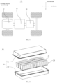
- Fig. 1 shows a structural schematic view of the vehicle according to some embodiments of the present application.
- the vehicle can be a fuel vehicle, a gas vehicle or a new energy vehicle.
- the new energy vehicles can be a pure electric vehicle, a hybrid vehicle, an extended-range vehicle and the like.
- a battery 10 may be arranged at an inside of the vehicle, and the battery 10 may be arranged at the bottom, the front or the back of the vehicle.
- the battery 100 can be used to supply power to the vehicle, for example, the battery 10 can be used as an operating power source of the vehicle.
- the vehicle may further include a controller 11 and a motor 12, the controller 11 can be used to control the battery 10 to supply power to the motor 12, for example, for starting, navigating and driving the vehicle.
- the battery 10 can not only be used as an operating power source for the vehicle, but can also be used as a driving power source for the vehicle, replacing or partially replacing the fuel oil or the natural gas to provide driving power for the vehicle.
- the battery 10 may include a plurality of battery cells.
- the battery cell refers to the smallest unit constituting a battery module or a battery pack.
- the plurality of battery cells can be connected in series and/or in parallel through an electrode terminal to apply to various application scenarios.
- the battery referred to in the present application may include the battery module or the battery pack.
- the plurality of battery cells can be connected in series, in parallel or in hybrid.
- the connection in hybrid refers to the combination of the connection in series and the connection in parallel.
- the battery 10 can also be referred to as the battery pack.
- the plurality of battery cells can directly form the battery pack, or can form the battery assembly firstly, and then form the battery pack.
- Fig. 2 shows a structural schematic view of the battery 10 according to an embodiment of the present application.
- the battery 10 can include a plurality of battery assemblies 20 and a housing 30, and the plurality of battery assemblies 20 can be accommodated in the housing 30.
- the housing 30 can be used to accommodate battery cells 21 or the battery assemblies 20 to prevent the charging or discharging of battery cells from being affected by the liquids or other foreign objects.
- the housing 30 can be a simple three-dimensional structure such as a single cuboid, a single cylinder or a single sphere, the housing 30 can also be a complex three-dimensional structure composed of the simple three-dimensional structures such as a cuboid, a cylinder or a sphere, and the embodiments of the present application do not restrict to that.
- the material of housing 30 can be an alloy material such as aluminum alloy, iron alloy or the like, or a polymer material such as a polycarbonate, a polyisocyanurate foam plastic or the like, or a composite material such as glass fiber, epoxy resin or the like, and the embodiments of the present application do not restrict to that.
- the housing 30 may include a first portion 31 and a second portion 32, the first portion 31 and the second portion 32 can cover each other, and the first portion 31 and the second portion 32 jointly define an accommodating space for accommodating the battery cells 21.
- the second portion 32 can be a hollow structure with an opening at an end
- the first portion 31 can be a plate-shaped structure
- the first portion 31 can cover on an opening side of the second portion 32 to form the casing with the accommodating space.
- each of the first portion 31 and the second portion 32 can also be the hollow structure with the opening on a side, and the opening side of the first portion 31 can cover the opening side of the second portion 32.
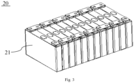
- Fig. 3 schematically shows a structural schematic view of a battery assembly 20 according to an embodiment of the present application.
- the battery assembly 20 includes a plurality of battery cells 21.
- the plurality of battery cells 21 may be connected in series, in parallel, or in hybrid to form the battery assembly 20 firstly, then the plurality of battery assembly 20 are connected in series, in parallel, or in hybrid to form the battery.
- the battery cell 21 can include a lithium ion battery cell, a sodium ion battery cell, a magnesium ion battery cell or the like, and the embodiments of the present application do not restrict to that.
- the battery cell 21 can be in a shape of cylinder, flat shape, cuboid or other shapes, and the embodiments of the present application do not restrict to that.
- the battery cell 21 can be divided into three types according to the packaging method: a cylindrical battery cell, a square battery cell, and a soft pack battery cell, and the embodiments of the present application do not restrict to that.
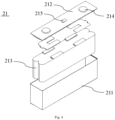
- Fig. 4 schematically shows an exploded structural schematic view of a battery cell 21 according to an embodiment of the present application.
- the battery cell 21 includes a casing 211, end cover 212 and an electrode assembly 213.
- the end cover 212 refers to a component that covers an opening of the casing 211 to isolate an internal environment of the battery cell 21 from an external environment.
- the shape of the end cover 212 can adapt to the shape of the casing 211 to match with the casing 211.
- the end cover 212 can be made of a material (such as aluminum alloy) with a certain hardness and strength, so that the end cover 212 may be less prone to deformation when subjected to compression and collision, the battery cell 21 is enabled to obtain a higher structural strength, and the safety performance can be improved.
- the end cover 212 can be made of various materials, such as copper, iron, aluminum, stainless steel, aluminum alloy or plastic, and the embodiments of the present application do not specially restrict to that.
- an insulating member can also be arranged on an inner side of the end cover 212, and the insulating member can be used to isolate the electrical connection parts in the casing 211 from the end cover 212 to reduce the risk of the short circuit.
- the insulating member may be a plastic, a rubber or the like.
- the casing 211 may be an assembly used to match with the end cover 212 to form the internal environment of the battery cell 21.
- the formed internal environment can be used to accommodate the electrode assembly 213, electrolyte and other parts.
- the casing 211 and the end cover 212 can be independent parts, and an opening can be formed on the casing 211.
- the end cover 212 can cover the opening at the place of the opening to form the internal environment of the battery cell 21.
- the end cover 212 and the casing 211 can also be integrated. Specifically, the end cover 212 and the casing 211 can form a common connecting surface before other parts entering into the shell firstly, then the end cover 212 can cover the casing 211 when it is necessary to package an interior of the casing 211.
- the casing 211 can be of various shapes and sizes, such as a rectangle, a cylinder, a hexagonal prism or the like. Specifically, the shape of the casing 211 can be determined based on the specific shape and size of the electrode assembly.
- the casing 211 can be made of various materials, such as copper, iron, aluminum, stainless steel, aluminum alloy or plastic, and the embodiments of the present application do not specially restrict to that.
- the present application provides a battery 10 including a battery array 20 formed by M*N battery cell(s) 21 arranged in M rows and N columns, M ⁇ 1, N ⁇ 1, and both M and N being positive integers.
- the battery cell(s) 21 in each row of the battery array 20 is(are) arranged in the first direction, which is the length direction of the battery 10 or the travelling direction of the electric-consuming device 1 including the battery 10, and the battery cell(s) 21 in each column of the battery array 20 is(are) arranged in the second direction, which intersects with the first direction and a vertical plane.
- a maximum size of the battery cell 21 in the second direction is D
- a maximum size of the battery array 20 in the second direction is D1
- the battery array 20 may be a structure with at least one row and at least one column, such as two rows and one column, one row and two columns, or two rows and two columns. As shown in Fig. 31 , in the embodiments as shown in the drawings of the present application, the battery array 20 is the structure with a plurality of rows (three or more rows) and a plurality of columns (three or more columns).
- the battery 10 is a substantially cubic structure with the length direction, a width direction and a height direction.
- the first direction is the length direction of the battery 10 or the travelling direction of the electric-consuming device 1.
- the length direction of the battery 10 can be the same or different from a driving direction.
- the second direction and the first direction are located in the same plane and intersect with each other.
- the present application further provides a third direction. Any two the third direction, the second direction and the first direction intersect with each other.
- all the battery cells 21 form the battery array 20.
- Each column of the battery array 20 is arranged in the first direction, and each row of the battery array 20 is arranged in the second direction.
- the maximum size of the battery cell 21 is D
- the maximum size of the battery array 20 is D1.
- a value of N*D/D1 ranges within [0.70, 0.99], so that the structure of the battery array 20 formed by all the battery cells 21 can be more compact.
- the battery array 20 can also be referred to as a battery assembly.
- N*D/D1 the higher the space utilization efficiency of the battery 10 is, and the higher the energy density of battery 10 is.
- the value of N*D/D1 cannot be set to 1.
- the value of N* D/D 1 is set within the range of [0.70, 0.99], which can make the structure of battery array 20 more compact while meeting the using requirements of the battery 10, so as to improve the space utilization efficiency and the energy density of the battery 10.
- the value of N*D/D1 may be 0.70, 0.75, 0.80, 0.85, 0.90, 0.95... 0.99.
- the maximum size of the battery cell 21 is D
- the maximum size of the battery array 20 is D1
- N*D/D1 ⁇ [0.83, 0.99] Specifically, by further setting the value of N*D/D1 within the range of [0.83, 0.99], the battery array 20 can fully utilize its performance and have a more compact structure, which is conducive to improving the space utilization and energy density of the battery 10.
- N*D/D1 may be 0.83, 0.85, 0.87, 0.89, 0.90, 0.92... 0.99.
- the length direction of battery cell 21 is consistent with the first direction
- the width direction of battery cell 21 is consistent with the second direction
- the height direction of battery cell 21 is consistent with the third direction
- D is the width of battery cell
- D1 is the width of battery array 20 in the width direction of battery cell 21.
- the energy density of battery 10 gradually increases when the value of N*D/D1 approaches to 1. Therefore, by reasonably controlling the value of N*D/D1, it can ensure that the battery 10 has the high energy density while the battery 10 can fully exert its performance.
- the length direction of the battery 10 is parallel to or intersects with the travelling direction of the electric-consuming device 1.
- the travelling direction of the electric-consuming device 1 refers to the direction in which the electric-consuming device 1 can generate the relative displacement, which can be forward or backward.
- the length direction of battery 10 is parallel to the travelling direction of the electric-consuming device 1, the length direction of the battery 10 is set in the travelling direction of electric-consuming device 1; when the length direction of battery 10 intersects with the travelling direction of electric-consuming device 1, the length direction of battery 10 is set at an angle to the travelling direction of electric-consuming device 1, in which the angle is not equal to 0.
- the battery 10 can be mounted on the electric-consuming device 1 according to the requirements of the electric-consuming device 1, so that the convenience of arrangement of the battery 10 in the electric-consuming device 1 can be improved.
- an adhesive is provided between two adjacent battery cells 21.
- the battery array 20 is arranged in M rows and N columns.
- the number of battery cells 21 in each row is more than or equal to two
- the two adjacent battery cells in each row can be connected and fixed by the adhesive.
- the structure of the battery array is simple and easy to be achieved during assembly, which can accelerate the production rhythm and improve production efficiency.
- the adhesive used to connect the two adjacent battery cells 21 in each row mat be a paste-like substance or a double-sided adhesive.
- the row in the battery array 20 can be arranged in the first direction or the second direction.
- the adhesive used to connect the two adjacent battery cells 21 in each column mat be a paste-like substance or a double-sided adhesive.
- the column in the battery array 20 can be arranged in the first direction or the second direction.
- the battery array 20 is arranged in M rows and N columns.
- the number of battery cells 21 in each column is more than or equal to two
- the two adjacent battery cells 21 in each column can be connected and fixed by the adhesive.
- the structure of the battery array is simple and easy to be achieved during assembly, which can accelerate the production rhythm and improve production efficiency.
- each two adjacent battery cells 21 are spaced apart from each other.
- the battery array 20 includes M rows and N columns.
- M rows and N columns are more than 1, two adjacent battery cells 21 in each row are spaced apart from each other, and two adjacent battery cells 21 in each column of the battery cells 21 are spaced apart from each other.
- the direct contact between the two adjacent battery cells 21 can be avoided.
- the battery cells 21 deform the impact on the adjacent battery cells 21 can be reduced, and the safety of the battery 10 can be improved during using.
- battery cells 21 will expand during using. If the two adjacent battery cells 21 abut against each other, once one of the battery cells 21 expands, it will compress the other battery cell 21, thereby affecting the performance of the other battery cell 21.
- a separating part is arranged between two adjacent battery cells 21.
- the two adjacent battery cells 21 can be spaced apart from each other, thereby reducing the adverse effect between the two adjacent battery cells 21, allowing the battery 10 to fully perform, and improving the safety of the battery 10 during using.
- the separating part is arranged between two adjacent battery cells 21 in each row, thereby improving the overall strength of battery array 20, reducing the adverse effect from the external factors such as vibration on battery array 20, and effectively enhancing the adaptability of battery 10.
- a separating part is arranged between two adjacent battery cells 21 are spaced apart from each other.
- the two adjacent battery cells 21 can be spaced apart from each other, thereby reducing the adverse effect between the two adjacent battery cells 21, allowing the battery 10 to fully perform, and improving the safety of the battery during using.
- the separating part is arranged between two adjacent battery cells 21 in each column, thereby improving the overall strength of battery array 20, reducing the adverse effect from the external factors such as vibration on battery array 20, and effectively enhancing the adaptability of battery 10.
- the separating part is bonded and fixed to the battery cells 21.
- the separating part is connected and fixed to the battery cells 21 through the adhesive; by means of bonding and fixing, the structure can be simple and easy to be achieved during assembly, which can accelerate the production rhythm, improve production efficiency and reduce the manufacturing cost.
- the separating part includes at least one of a thermal conductive member 40, a buffer member, a separating plate or a separating beam.
- the separating part can be provided as at least one of the thermal conductive member 40, the buffer member, the separating plate or the separating beam.
- the corresponding separating part can be provided according to different requirements, so as to meet the corresponding using requirements of the battery array 20.
- the separating part is a buffer member, which is arranged between two adjacent battery cells 21.
- the buffer member can eliminate the tolerance of the two adjacent battery cells 21 generated in the manufacturing process, thereby ensuring the effective mounting of the battery cells 21.
- the buffer member can provide the buffer between the two adjacent battery cells 21, thereby reducing the risk of compression and damage between the two adjacent battery cells 21.
- the separating part may be the separating plate, which is arranged between two adjacent battery cells 21.
- the separating plate can be used to separate the two adjacent battery cells 21 to prevent them from being crushed and damaged by each other.
- the separating part may be the separating beam, which is arranged between two adjacent battery cells 21.
- the separating beam can be used to separate the two adjacent battery cells 21 to prevent them from being crushed and damaged by each other.
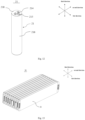
- the battery cell 21 includes a plurality of surfaces, which include a first surface 216 and a second surface 217; the first surface 216 is a surface with the largest area, and an area of the second surface 217 is smaller than that of the first surface 216; the first surface 216 is arranged in the first direction and intersects with a horizontal plane, and the second surface 217 is arranged in the second direction and intersects with the horizontal plane; in the first direction, the second surfaces 217 of two adjacent battery cells 21 in each column of the battery cells 21 are arranged opposite to each other, and in the second direction, the first surfaces 216 of two adjacent battery cells 21 in each row are arranged opposite to each other.
- the first surface 216 is the surface of the battery cell 21 with the largest area, and the first surface 216 is arranged in the first direction and intersects with a horizontal plane.
- a thermal conductive member 40 can be arranged on a side of the first surface 216. By utilizing the thermal connection between the thermal conductive member 40 and the first surface 216, the contact area between the thermal conductive member 40 and the battery cell 21 can increase, so as to improve the heat dissipation efficiency of the battery cell 21.
- the first surface 216 is the surface with the largest area of the battery cell 21. The first surface 216 is arranged in the first direction and intersects with the horizontal plane.
- a corresponding reinforcement structure (such as a reinforcement beam or a reinforcement rib) can be arranged on a side of the housing 30 corresponding to the first surface 216, so as to improve the protective performance to the battery cell 21.
- the first surface 216 is the surface of the battery cell 21 with the largest area, and the area of the second surface 217 is smaller than that of the first surface 216.
- the two surfaces can combine with other surfaces of the battery cell 21 to form various forms of battery cell 21, such as a cubic casing battery cell, a blade-shaped battery cell and an one-stop battery cell.
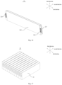
- the battery cell 21 includes a plurality of surfaces, which include a first surface 216 and a second surface 217; the first surface 216 is a surface with the largest area, and an area of the second surface 217 is smaller than that of the first surface 216; the second surface 217 is arranged in the first direction and intersects with a horizontal plane, and the first surface 216 is arranged in the second direction and intersects with the horizontal plane; the first surfaces 216 of two adjacent battery cells 21 in each column of the battery cells 21 are arranged opposite to each other in the first direction, and the second surfaces 217 of two adjacent battery cells 21 in each row are arranged opposite to each other in the second direction.
- the first surface 216 is the surface of the battery cell 21 with the largest area, and the first surface 216 is arranged in the second direction and intersects with a horizontal plane.
- a thermal conductive member 40 can be arranged on a side of the first surface 216. By utilizing the thermal connection between the thermal conductive member 40 and the first surface 216, the contact area between the thermal conductive member 40 and the battery cell 21 can increase, so as to improve the heat dissipation efficiency of the battery cell 21.
- the first surface 216 is the surface with the largest area of the battery cell 21.
- the first surface 216 is arranged in the second direction and intersects with the horizontal plane.
- a corresponding reinforcement structure (such as a reinforcement beam or a reinforcement rib) can be arranged on a side of the housing 30 corresponding to the first surface 216, so as to improve the protective performance to the battery cell 21.
- the first surface 216 is the surface of the battery cell 21 with the largest area, and the area of the second surface 217 is smaller than that of the first surface 216.
- the two surfaces can combine with other surfaces of the battery cell 21 to form various forms of battery cell 21, such as a cubic casing battery cell, a blade-shaped battery cell and an one-stop battery cell.
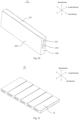
- the battery cell 21 includes a plurality of surfaces, which include a first surface 216 with the largest area; the first surfaces 216 of two adjacent battery cells 21 in each column of the battery cells 21 are arranged opposite to each other in the first direction, and the first surfaces 216 of two adjacent battery cells 21 in each row are misaligned with each other in the second direction.
- the first surface 216 is the surface of the battery cell 21 with the largest area.
- the first surface can combine with other surfaces of the battery cell 21 to form a cylindrical battery cell 21, such as a cubic casing battery cell, a blade-shaped battery cell and an one-stop battery cell.
- the battery cell 21 includes a plurality of surfaces, which include a first surface 216 with the largest area; the first surfaces 216 of two adjacent battery cells 21 in each column of the battery cells 21 are misaligned with each other in the first direction, and the first surfaces 216 of two adjacent battery cells 21 in each row are arranged opposite to each other in the second direction.
- the first surface 216 is the surface of the battery cell 21 with the largest area.
- the first surface can combine with other surfaces of the battery cell 21 to form a cylindrical battery cell 21, such as a cubic casing battery cell, a blade-shaped battery cell and an one-stop battery cell.
- the separating part includes a thermal conductive member 40, which is arranged in the first direction and intersects with the second direction, the thermal conductive member 40 is arranged on at least one side of each column of the battery cells 21, and each column of the battery cells 21 are thermally connected to one thermal conductive member 40.
- the thermal conductive member 40 is arranged in the housing 30 of the battery 10 and arranged in the first direction.
- the thermal conductive member 40 is arranged on at least one side of each column of the battery cells 21, so as to achieve the effective heat dissipation for the battery cells 21 in each column, maintain the battery cells 21 within a relatively safe operating temperature range and improve the using safety of the battery 10.
- the surface of the battery cell 21 thermally connected to the thermal conductive member 40 may be the surface with of the battery cell 21 with the largest area.
- the contact area between the thermal conductive member 40 and the battery cell 21 can increase, so as to improve the heat dissipation performance of the battery cell 21.
- the contact area between the thermal conductive member 40 and the battery cell 21 may be not the largest surface area, so as to meet the requirements of different mounting and arrangement inside battery cell 21.
- thermal conductive member 40 can be arranged on one side of each column of the battery cell 21, or the thermal conductive members 40 can be arranged on two side of each column of the battery cell, respectively, so as to meet the heat dissipation requirements of the battery 10.
- the thermal conductive member 40 may be an electronic cooling sheet, such as a PTC.
- a channel is provided inside the thermal conductive member 40 to accommodate a heat-exchanging medium.
- the thermal conductive member 40 communicates with a medium circulation device, and the channel is filled with the heat-exchange medium (such as water or oil), which can circulate in the channel.
- the battery cells 21 transfer the heat to the heat-exchanging medium in the channel through the thermal conductive member 40.
- the heat-exchanging medium flows in the channel and carries out the heat exchanged with the battery cell 21.
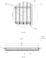
- the battery 10 further includes at least one current collector 50, which fluidly communicates with the thermal conductive member 40.
- the current collector 50 is located at one end of the thermal conductive member 40 in the first direction, or the current collectors 50 are located at two ends of the thermal conductive member 40 in the first direction, respectively.
- the current collector 50 is arranged at one end of the thermal conductive member 40 in the first direction, or the current collectors 50 are arranged at two ends of the thermal conductive member 40 in the first direction, respectively.
- the current collector 50 By arranging the current collector 50, it can achieve the collection of the heat-exchanging medium inside the thermal conductive member 40, reduce the number of the parts, and thus improve the space utilization efficiency inside the housing 30.
- the arranging position of the current collector 50 can avoid the compression or impact, so as to reduce the possibility of damage to the current collector 50, so that the heat-exchange medium can fully dissipate the heat from the battery 10, and further reduce the safety hazards caused by the high temperature of the battery 10.
- the battery includes two current collectors 50, which are located at one end of the thermal conductive member 40 in the first direction and arranged in a third direction. Any two of the first direction, the second direction and the third direction intersect with each other.
- the current collecting performance of the heat-exchanging medium can be improved, so that the heat-exchanging medium can have a good flow rate, which can further improve the heat exchanging ability of the heat-exchanging medium to the battery cells 21.
- the space occupied by the current collectors 50 in the battery 10 in the first direction can be effectively reduced, thereby facilitating arranging other structures inside the battery 10.
- the separating part includes a thermal conductive member 40, which is arranged in the second direction and intersects with the first direction.
- the thermal conductive member 40 is arranged on at least one side of each row of the battery cells 21, and each row of the battery cells 21 are thermally connected to one thermal conductive member 40.
- the thermal conductive member 40 is arranged in the housing 30 of the battery 10 and arranged in the second direction.
- the thermal conductive member 40 is arranged on at least one side of each column of the battery cells 21, so as to achieve the effective heat dissipation for the battery cells 21 in each column, maintain the battery cells 21 within a relatively safe operating temperature range and improve the using safety of the battery 10.
- the surface of the battery cell 21 thermally connected to the thermal conductive member 40 may be the surface with of the battery cell 21 with the largest area.
- the contact area between the thermal conductive member 40 and the battery cell 21 can increase, so as to improve the heat dissipation performance of the battery cell 21.
- the contact area between the thermal conductive member 40 and the battery cell 21 may be not the largest surface area, so as to meet the different requirements of mounting and arrangement inside battery cell 21.
- thermal conductive member 40 can be arranged on one side of each column of the battery cell 21, or the thermal conductive members 40 can be arranged on two side of each column of the battery cell, respectively, so as to meet the heat dissipation requirements of the battery 10.
- the thermal conductive member 40 may be an electronic cooling sheet (such as a PTC), and the thermal conductive member 40 can be provided with the channel for accommodating the heat-exchanging medium.
- an electronic cooling sheet such as a PTC
- the battery cell 21 includes an electrode assembly 213, which includes a main body 2131 and an electrode tab 2132 protruding from the main body 2131, the electrode tab 2132 is electrically connected to the electrode terminal 214, and a projection of the thermal conductive member 40 and a projection of the main body 2131 at least partially overlap with each other to form an overlapping region in the second direction.
- the heating of the battery cell 21 is mainly concentrated on the main body 2131 of electrode assembly 213.
- the thermal conductive member 40 can effectively exchange the heat of the main body 2131, so that he battery cell 21 can be maintained at a safe temperature, thereby improving the using safety.
- a size of the main body 2131 is L1
- a size of the thermal conductive member 40 is L2
- any two of the first direction, the second direction and the third direction intersect with each other, and 0.5 ⁇ L2/L1 ⁇ 1.5.
- the space occupied by the thermal conductive member 40 in the third direction can be reduced, and the space utilization efficiency of the battery 10 can be further improved.
- L2/L1 may be 0.5, 0.6, 0.7, 0.8, 0.9, 1.0, 1.1, 1.2, 1.3, 1.4... 1.5.
- a size of the overlapping region is L3, and 0.5 ⁇ L3/L1 ⁇ 1.
- the heat exchanging area between the thermal conductive member 40 and the main body 2131 can be reasonably set, thereby greatly improving the heat exchanging effect of the thermal conductive member 40 on the main body 2131.
- L3/L1 may be 0.5, 0.6, 0.7, 0.8, 0.9... 1.
- the battery cell 21 includes an electrode terminal 214, which is arranged on at least one of the plurality of surfaces.
- the electrode terminal 214 by arranging the electrode terminal 214, the electrode terminal of the battery 10 can achieve the electrical discharge of the battery cells 21, thereby ensuring that the battery cells 21 can effectively perform the charging and discharging operations.
- the battery cell 21 has the plurality of surfaces, and the electrode terminal 214 can be arranged on the corresponding surface of the battery cell 21 according to the requirements.
- the plurality of surfaces further include at least one third surface 218. Any two of the first surface 216, the second surface 217 and the third surface 218 intersect with each other, and the electrode terminal 214 is arranged on the third surface 218.
- the battery cell 21 includes the plurality of surfaces including the first surface 216 with the largest area, the second surface 217 and the third surface 218, in which the area of either the second surface 217 or the third surface 218 is smaller than that of the first surface 216.
- the electrode terminal 214 is arranged on the third surface 218, so that the first surface 216 can be thermally connected to the thermal conductive member 40, so as to prevent the interference between the electrode terminal 214 and the thermal conductive member 40, ensure the effective thermal conductivity between the thermal conductive member 40 and the battery cell 21, and improve the heat dissipation effect of the thermal conductive member 40 on the battery cell 21.
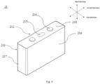
- the plurality of surfaces further include two third surfaces 218, the two third surfaces 218 are arranged opposite to each other and intersect with the first surface 216, the battery cell 21 includes two electrode terminals 214 with opposite polarities. As shown in Fig. 7 and Fig. 9 , the two electrode terminals 214 with the opposite polarities are both arranged on one of the two third surfaces 218, or the two electrode terminals 214 with the opposite polarities are arranged on the two third surfaces 218, respectively.
- the battery cell 21 includes the plurality of surfaces including the first surface 216, the second surface 217 and the third surface 218.
- the first surface 216 has the largest area, and the area of either the second surface 217 or the third surface 218 is smaller than that of the first surface 216.
- two electrode terminals 214 with the opposite polarities can be both arranged on one of the two third surfaces 218, or the two electrode terminals 214 with the opposite polarity can be arranged on the two third surfaces 218, respectively.
- two electrode terminals 214 with the opposite polarities can be both arranged on one of the two third surfaces 218, or the two electrode terminals 214 with the opposite polarity can be arranged on the two third surfaces 218, respectively.
- the structure of the battery cell 21 can meet the mounting requirements of different batteries 10, thereby improving the applicability of the battery cell 21.
- the battery cell 21 includes the first surface 216 and a fourth surface arranged opposite to the first surface 216, the first surface 216 and the fourth surface are arranged opposite to each other in the first direction (as shown in Fig. 14 ) or the second direction (as shown in Fig. 16 ). Any two of the second direction, the first direction and the third direction intersect with each other.
- a concave part is arranged at an edge of the fourth surface.
- the first surface 216 is configured to arrange the electrode terminal 214, which protrudes from the first surface in the second direction and corresponds to the concave part.
- the battery cell 21 includes the plurality of surfaces, including the first surface 216 with the largest area, and further including the fourth surface.
- the first surface 216 and the fourth surface are arranged opposite to each other in the first direction or the second direction.
- the electrode terminal 214 of one battery cell 21 corresponds to the concave part of the other battery cell 21.
- the combination structure formed by the two adjacent battery cells 21 can be more compact by using a concave structure and a convex structure matching with each other, so that the structure of battery array 20 can be more compact, which can be conducive to improving the space utilization efficiency and the energy density of the battery 10.
- the structure of the battery cell 21 can meet the mounting requirements of different batteries 10, thereby improving the applicability of the battery cell 21.
- the plurality of surfaces further include a third surface 218. Any two of the first surface 216, the second surface 217 and the third surface 218 intersect with each other.
- the third surface 218 has the largest area, and the area of either the first surface 216 or the second surface 217 is smaller than that of the third surface 218.
- the first surface 216 is arranged in the first direction and intersects with the horizontal plane, and the second surface 217 is arranged in the second direction and intersects with the horizontal plane.
- the first surface 216 is arranged in the second direction and intersects with the horizontal plane, and the second surface 217 is arranged in the first direction and intersects with the horizontal plane.
- the electrode terminal 214 can be arranged on the first surface 216 or the second surface 217. By arranging the position of the electrode terminal 214, the structure of the battery cell 21 can meet the mounting requirements of different batteries 10, thereby improving the applicability of the battery cell 21.
- the battery cell 21 includes two electrode terminals 214 with opposite polarities. As shown in Fig. 7 and Fig. 9 , the two electrode terminals 214 are both arranged on the third surface 218. Alternatively, as shown in Fig. 12 , one of the two electrode terminals 214 with opposite polarities is arranged on the third surface 218, and a casing 211 of the battery cell 21 forms the other one of the two electrode terminals 214.
- the battery cell 21 includes the plurality of surfaces including the first surface 216 with the largest area, the second surface 217 and the third surface 218, in which the area of either the second surface 217 or the third surface 218 is smaller than that of the first surface 216.
- the battery cells 21 in each column include at least two battery cells 21, which are arranged in the first direction.
- At least two battery cells 21 are arranged in the first direction, so as to facilitate the arrangement of the battery cells 21 inside the housing 30.
- the large surfaces (the surface with the largest area) of the battery cells 21 can be arranged in the first direction and intersect with the horizontal plane, or arranged in the second direction and intersect with the horizontal plane.
- a maximum size of the battery cell 21 in the first direction, is L; in the second direction, a maximum size of the battery cell 21 is D; and a value of L/D ranges from 1 to 30.
- the maximum size of the battery cell 21 in the first direction is L
- the maximum size of the battery cell 21 in the second direction is D.
- LID may be 1, 2, 3, 4, 5, 6, 7, 8... 30.
- the battery cell 21 can have different shapes, thereby meeting the requirements of different forms of batteries 10.
- a maximum size of the battery cell 21 is H; a value of L/H ranges from 0.5 to 6; and any two of the first direction, the second direction and the third direction intersect with each other.
- the maximum size of the battery cell 21 is L.
- the maximum size of the battery cell 21 in the first direction is L, and a maximum size of the battery cell 21 in the third direction is H.
- the size of the battery cell 21 is set according to the above-mentioned ratio, so that the electric power of battery cell 21 can increase as much as possible while the support strength of the battery cell 21 can be ensured.
- L/H may be 0.5, 1, 1.5, 2, 2.5, 3, 3.5, 4... 6.
- the battery cell 21 can have different shapes, thereby meeting the requirements of different forms of batteries 10.
- the battery 10 further includes a housing 30.
- the battery array 20 can be more suitable for the housing 30 of the battery 10, and can effectively improve the space utilization efficiency of the battery 10 while meeting the mounting requirements of the battery array 20, so that the energy density of the battery 10 can be effectively increased.
- n when the value of n is less than 0.7, the space utilization efficiency and the energy density of the battery 10 will be reduced; when the value of n is larger than 0.99, it cannot be ensured that the battery array 20 can be effectively mounted inside the housing 30. Therefore, by setting the value of n within the range of [0.7, 0.99], the requirement of mounting of the battery array can be effectively met, the space utilization efficiency of the battery can be improved, and the energy density of the battery can be improved.
- n may be 0.7, 0.75, 0.8, 0.85, 0.9, 0.95... 0.99.
- the battery cells 21 are fixedly connected to the housing 30 through a first adhesive layer 60
- the battery 10 further includes a thermal conductive member 40, which is thermally connected to the battery cells 21 through a second adhesive layer 70, and a thermal conductive coefficient of the first adhesive layer 60 is less than or equal to that of the second adhesive layer 70.
- the thermal conductive coefficient of the first adhesive layer 60 is set to be less than or equal to that of the second adhesive layer 70, so as to ensure more effective heat dissipation for the battery cells 21 through the thermal conductive member 40.
- a ratio of the thermal conductive coefficient of the first adhesive layer 60 to the thermal conductive coefficient of the second adhesive layer 70 ranges from 0.1 to 1.
- the battery cells 21 can effectively dissipate heat through the thermal conductive member 40.
- the ratio of the thermal conductive coefficient of the first adhesive layer 60 to the thermal conductive coefficient of the second adhesive layer 70 is less than 0.1, the thermal conductivity of the first adhesive layer 60 is poor, and a side of the battery cell 21 connected to the first adhesive layer 60 cannot exchange heat through a side of the first adhesive layer 60. In this case, the heat exchanging only through one side of the second adhesive layer 70 cannot ensure the good heat dissipation effect on the battery cell 21.
- the ratio of the thermal conductive coefficient of the first adhesive layer 60 to the thermal conductive coefficient of the second adhesive layer 70 is less than 0.1, the thermal conductivity of the first adhesive layer 60 is stronger than that of the second adhesive layer 70. The ability of the battery cell 21 to dissipate heat through the thermal conductive member 40 is weakened, which will lead to the deterioration in the heat dissipation effect of the battery cell 21.
- the ratio of the thermal conductive coefficient of the first adhesive layer 60 to the thermal conductive coefficient of the second adhesive layer 70 may be 0.1, 0.2, 0.3, 0.4, 0.5, 0.6, 0.7, 0.8, 0.9... 1.
- the first adhesive layer 60 and the second adhesive layer 70 can be the same type of adhesive, but the thermal conductive coefficients of the first adhesive layer and the second adhesive layer may be different. That is, the thermal conductive coefficient of the first adhesive layer 60 is smaller than that of the second adhesive layer 70.
- the first adhesive layer 60 and the second adhesive layer 70 can adopt thermal conductive polyurethane adhesive layers, respectively, and different amounts of thermal conductive particles can be added to the thermal conductive polyurethane adhesive layers, respectively, to achieve different thermal conductive coefficients.
- first adhesive layer 60 and the second adhesive layer 70 can adopt two different types of adhesives, respectively.
- first adhesive layer 60 may be a structural adhesive, a foam-filling adhesive, a pressure-sensitive adhesive, a sealing adhesive or the like
- second adhesive layer 70 may be a thermal conductive adhesive or the like.
- the battery cell 21 includes an electrode assembly 213, which is in a winding structure and in a shape of a flat, an outer surface of the electrode assembly 213 includes two flat planes, which face to each other in the second direction; or the electrode assembly 213 is in a stacked structure and includes a first electrode plate, a separator and a second electrode plate, which are stacked in the second direction.
- the electrode assembly 213 is a component in the battery cell 21 that produces an electrochemical reaction.
- One or more electrode assemblies 213 are arranged inside the battery cell 21.
- the electrode assembly 213 is substantially formed by winding or stacking electrode plates (a positive electrode plate and a negative electrode plate), and a separator is generally arranged between the positive electrode plate (first electrode plate) and the negative electrode plate (second electrode plate).
- the main body 2131 of the electrode assembly 213 is formed by portions of the electrode plates (first electrode plate and second electrode plate) that include the active substance, and other portions of the positive electrode plate and the negative electrode plate that do not include the active substance form electrode tabs 2132, respectively.
- the positive electrode tab and the negative electrode tab can be located at one end of the main body 2131 or at two ends of the main body 2131, respectively.
- the electrode assembly 213 is in the winding structure and in the shape of the flat, the outer surface of the electrode assembly 213 includes two flat planes, which face to each other in the second direction, or the electrode assembly 213 is in the stacked structure, so that the space occupied by the electrode assembly 213 in the second direction can be reduced, so as to facilitate the arrangement and mounting of other parts in the first direction by the battery 10.
- the battery cell 21 further includes a press-releasing mechanism 215, which is arranged on any one of the surfaces of the battery cell.
- the pressure inside the battery cell 21 can be released through the press-releasing mechanism 215 in time to avoid the safety risk such as explosion of the battery cell 21.
- press-releasing mechanism 215 can be arranged on the first surface 216, the second surface 217, the third surface 218 or another surface of the battery cell 21.
- the press-releasing mechanism 215 and the electrode terminal 214 can be arranged on the first surface 216, the second surface 217 or the third surface 218.
- both the press-releasing mechanism 215 and the electrode terminal 214 are arranged on the first surface 216.
- the press-releasing mechanism 215 By arranging the press-releasing mechanism 215 on the first surface 216, it is convenient for the synchronous mountings of the press-releasing mechanism 215 and the electrode terminal 214, so as to improve the assembly convenience and improve the production efficiency.
- the second surface 217 is connected to the housing 30, thereby utilizing the housing 30 to form the protection on an outer side of the press-releasing mechanism 215, and reducing the possibility of the press-releasing mechanism 215 being impacted.
- the arranging position of the press-releasing mechanism 215 can meet the requirements of different types of the battery cells 21, thereby further improving the safety performance of the battery 10.
- the present application provides an electric-consuming device 1, including the battery 10 as described above, which is configured to provide electrical energy to drive the electric-consuming device 1 to move.
- the first direction is the travelling direction of the electric-consuming device 1.
- the first direction is set as the travelling direction of the electric-consuming device 1, and the third direction intersects with the first direction and the horizontal direction.
- the battery cell 21 located inside the housing 30 of the battery 10 includes the first surface 216 and the second surface 217.
- the first surface 216 is provided with the electrode terminal 214, and the second surface 217 is connected to the housing 30.
- By setting the first direction it can facilitate the mounting and arrangement of the battery 10 on the electric-consuming device 1.
- the present application provides the battery 10 including the battery array 20 formed by M*N battery cell(s) 21 arranged in M rows and N columns, M ⁇ 1, N ⁇ 1, and both M and N being positive integers.
- the battery cell(s) 21 in each row of the battery array 20 is(are) arranged in the first direction, which is the length direction of the battery 10 or the travelling direction of the electric-consuming device 1 including the battery 10, and the battery cell(s) 21 in each column of the battery array 20 is(are) arranged in the second direction, which intersects with the first direction and the vertical plane.
- the maximum size of the battery cell 21 in the second direction is D
- the maximum size of the battery array 20 in the second direction is D1
- all the battery cells 21 form the battery array 20.
- Each column of the battery array 20 is arranged in the first direction, and each row of the battery array 20 is arranged in the second direction.
- the maximum size of the battery cell 21 is D
- the maximum size of the battery array 20 is D1.
- the value of N*D/D1 ranges within [0.70, 0.99], so that the structure of the battery array 20 formed by all the battery cells 21 can be more compact.
- N*D/D1 is further set within the range of [0.83, 0.99].
- the battery 10 further includes the housing 30.
- the two adjacent battery cells 21 can be bonded and fixed by the adhesive.
- the separating part can be set between two adjacent battery cells 21 in each column, or between two adjacent battery cells 21 in each row.
- the separating part is bonded and fixed to the battery cells 21.
- the separating part includes at least one of the thermal conductive member 40, a buffer member, a separating plate or a separating beam.
- the separating part includes the thermal conductive member 40.
- the separating part includes the thermal conductive member 40, which is arranged in the housing 30 of the battery 10 and arranged in the first direction.
- the thermal conductive member 40 is thermally connected to the battery cell 21.
- the surface of the battery cell 21 for the thermal conductive connection between the battery cell 21 and the thermal conductive member 40 may be the surface of the battery cell 21 with the largest area.
- the heat-exchanging medium channel is arranged inside the thermal conductive member 40, and the heat-exchanging medium flows in the heat-exchanging medium channel. The heat transfer occurs between the thermal conductive member 40 and the battery cell 21 through the channel.
- the other parts of the separating part are bonded and fixed to the battery cell 21 through the first adhesive layer, and the thermal conductive member 40 is bonded and fixed to the battery cell 21 through the second adhesive layer.
- the ratio of the thermal conductive coefficient of the first adhesive layer to the thermal conductive coefficient of the second adhesive layer ranges from 0.1 to 1.
- the battery cell 21 includes the plurality of surfaces including the first surface 216, the second surface 217 and the third surface 218.
- first surface 216 is the surface with the largest area, there are two first surfaces and the two first surfaces 216 are arranged opposite to each other in the second direction, in this case, the second surfaces 217 of the two adjacent battery cells 21 in each column of the battery cells 21 are arranged opposite to each other, and the first surfaces 216 of the two adjacent battery cells 21 in each row are arranged opposite to each other.
- the first surface 216 is the surface with the largest area, there are two first surfaces and the two first surfaces 216 are arranged opposite to each other in the first direction, in this case, the first surfaces 216 of the adjacent two battery cells 21 in each column of the battery cells 21 are arranged opposite to each other, and the second surfaces 217 of the adjacent two battery cells 21 in each row are arranged opposite to each other.
- the first surface 216 is the surface with the largest area and there is one first surface, the first surface 216 can form a peripheral surface of the battery cell 21.
- the two adjacent battery cells 21 in each column of the battery cells 21 are arranged in the first direction, and the two adjacent battery cells 21 in each row are misaligned with each other, or the two adjacent battery cells 21 in each row are arranged in the first direction, and the two adjacent battery cells 21 in each column are misaligned with each other.
- the maximum size of battery cell 21 is L, and in the second direction, the maximum size of battery cell 21 is D.
- the value of LID ranges from 1 to 30.
- the maximum size of battery cell 21 is H, and the value of L/H ranges from 0.5 to 6.
- the battery cell 21 includes two electrode terminals 214 with the opposite polarities.
- the two electrode terminals 214 with the opposite polarities are arranged on the same surface of the battery cell 21 or on different surfaces of the battery cell 21, respectively.
- one electrode terminal is arranged the surface of the battery cell 21 and the other electrode terminal is formed by the casing 211 of the battery cell of the battery 10.
- the press-releasing mechanism 215 is arranged on the battery cell 21.
- the press-releasing mechanism 215 can be arranged on any one of the first surface 216, the second surface 217 and the third surface 218. In the structure shown in the drawings of the present application, both the press-releasing mechanism 215 and the electrode terminal 214 are arranged on the first surface 216.
- the projections of the thermal conductive member 40 and the main body 2131 at least partially overlap with each other to form the overlapping region.
- the size of the main body 2131 is L1
- the size of the thermal conductive member 40 is L2
- 0.5 ⁇ L2/L1 ⁇ 1.5 is 0.5 ⁇ L2/L1 ⁇ 1.5.
- the size of the overlapping region is L3, and 0.5 ⁇ L3/L1 ⁇ 1.
- the battery 10 further includes the current collector 50, which is located at the end of the thermal conductive member 40 in the first direction and communicates with the heat-exchanging medium channel of the thermal conductive member 40.
Landscapes
- Chemical & Material Sciences (AREA)
- Chemical Kinetics & Catalysis (AREA)
- Electrochemistry (AREA)
- General Chemical & Material Sciences (AREA)
- Engineering & Computer Science (AREA)
- Manufacturing & Machinery (AREA)
- Aviation & Aerospace Engineering (AREA)
- Battery Mounting, Suspending (AREA)
- Secondary Cells (AREA)
- Connection Of Batteries Or Terminals (AREA)
Abstract
Description
- The present application relates to the technical field of batteries, and in particular to a battery and an electric-consuming device.
- With the development of new energy, the new energy, as a power, is being applied in more and more fields. Due to the advantages such as high energy density, recyclable charging, safety and environmental protection, power batteries are widely used in fields such as a new energy vehicle, consumer electronics and energy storage system.
- The power battery usually includes a housing and a plurality of battery cells. The battery cells are arranged inside the housing. The arrangement of the battery cells in the prior art results in the low space utilization efficiency of the battery, which is not conducive to improving the energy density of the battery.
- In view of the above problem, the present application provides a battery and an electric-consuming device which can solve the problem of low space utilization efficiency of a battery in a prior art.
- In a first aspect, the present application provide a battery including a battery array formed by M*N battery cell(s) arranged in M rows and N columns, M≥1, N≥1, and both M and N being positive integers;
- the battery cell(s) in each row of the battery array is(are) arranged in a first direction, which is a length direction of the battery or a travelling direction of an electric-consuming device including the battery, and the battery cell(s) in each column of the battery array is(are) arranged in a second direction, which intersects with the first direction and a vertical plane;
- a maximum size of the battery cell in the second direction is D, a maximum size of the battery array in the second direction being D1, and N*D/D1∈[0.70, 0.99].
- According to the battery in the present application, all the battery cells form the battery array. Each column of the battery array is arranged in the first direction, and each row of the battery array is arranged in the second direction. In the second direction, the maximum size of the battery cell is D, and the maximum size of the battery array is D1. A value of N*D/D1 ranges within [0.70, 0.99], so that the structure of the battery array formed by all the battery cells can be more compact. When the battery array is arranged inside the battery, an internal space of the battery can be fully utilized, the space utilization efficiency of the battery can be improved, and the energy density of the battery can be improved.
- In some embodiments of the present application, N*D/D1∈[0.83, 0.99]. In this embodiment, by further setting the value of N*D/
D 1 within the range of [0.83, 0.99], the battery array can fully utilize its performance and have a more compact structure, which is conducive to improving the space utilization and energy density of the battery. - In some embodiments of the present application, the length direction of the battery is parallel to or intersects with the travelling direction of the electric-consuming device. In this embodiment, by arranging the length direction of the battery to be parallel to or intersect with the travelling direction of the electric-consuming device, the convenience of arrangement of the battery in the electric-consuming device can be improved.
- In some embodiments of the present application, in the battery array, M≥2, and in each row of the battery cells, an adhesive is provided between two adjacent battery cells; and/or
in the battery array, N≥2, in each column of the battery cells, an adhesive is provided between two adjacent battery cells. - In this embodiment, the battery array is arranged in M rows and N columns. When the number of battery cells in each column is more than or equal to two, the two adjacent battery cells in each column can be connected and fixed by the adhesive. When the number of battery cells in each row is more than or equal to two, the two adjacent battery cells in each row can be connected and fixed by the adhesive. By using the adhesive to connect and fix the two adjacent battery cells, the structure of the battery array is simple and easy to be achieved during assembly, which can accelerate the production rhythm and improve the production efficiency.
- In some embodiments of the present application, two adjacent battery cells are spaced apart from each other. In this embodiment, by spacing the two adjacent battery cells apart from each other, when the battery cells deform, the impact on the adjacent battery cells can be reduced, and the safety of the battery can be improved during using.
- In some embodiments of the present application, in the battery array, M≥2, and in each row of battery cells, a separating part is arranged between two adjacent battery cells; or
in the battery array, N≥2, and in each column of the battery cells, a separating part is arranged between two adjacent battery cells. - In this embodiment, by arranging the separating part between the two adjacent battery cells in each column, the two adjacent battery cells can be spaced apart from each other, thereby reducing the adverse effect between the two adjacent battery cells, allowing the battery to fully perform, and improving the safety of the battery during using. In addition, by arranging the separating part between the two adjacent battery cells in each row, the two adjacent battery cells can be spaced apart from each other, thereby reducing the adverse effect between the two adjacent battery cells, allowing the battery to fully perform, and improving the safety of the battery during using.
- In some embodiments of the present application, the separating part is bonded and fixed to the battery cells. In this embodiment, the separating part is connected and fixed to the battery cells through the adhesive; by means of bonding and fixing, the structure can be simple and easy to be achieved during assembly, which can accelerate the production rhythm, improve production efficiency and reduce the manufacturing cost.
- In some embodiments of the present application, the separating part includes at least one of a thermal conductive member, a buffer member, a separating plate or a separating beam. In this embodiment, the separating part can be provided as at least one of the thermal conductive member, the buffer member, the separating plate or the separating beam. On the basis of separating the two adjacent battery cells, the corresponding separating part can be provided according to different requirements, so as to meet the corresponding using requirements of the battery array.
- In some embodiments of the present application, the battery cell includes a plurality of surfaces, which include a first surface and a second surface; the first surface is a surface with the largest area, and an area of the second surface is smaller than that of the first surface; the first surface is arranged in the first direction and intersects with a horizontal plane, and the second surface is arranged in the second direction and intersects with the horizontal plane; in the first direction, the second surfaces of two adjacent battery cells in each column of the battery cells are arranged opposite to each other, and in the second direction, the first surfaces of two adjacent battery cells in each row are arranged opposite to each other.
- In this embodiment, the first surface is the surface of the battery cell with the largest area, and the area of the second surface is smaller than that of the first surface. By arranging the directions of the first surface and the second surface, the battery array can meet the requirements of different batteries and improve the applicability of the battery.
- In some embodiments of the present application, the battery cell includes a plurality of surfaces, which include a first surface and a second surface; the first surface is a surface with the largest area, and an area of the second surface is smaller than that of the first surface; the second surface is arranged in the first direction and intersects with a horizontal plane, and the first surface is arranged in the second direction and intersects with the horizontal plane; the first surfaces of two adjacent battery cells in each column of the battery cells are arranged opposite to each other in the first direction, and the second surfaces of two adjacent battery cells in each row are arranged opposite to each other in the second direction.
- In this embodiment, the first surface is the surface of the battery cell with the largest area, and the area of the second surface is smaller than that of the first surface. By arranging the directions of the first surface and the second surface, the battery array can meet the requirements of different batteries and improve the applicability of the battery.
- In some embodiments of the present application, the battery cell includes a plurality of surfaces, which include a first surface with the largest area; the first surfaces of two adjacent battery cells in each column of the battery cells are arranged opposite to each other in the first direction, and the first surfaces of two adjacent battery cells in each row are misaligned with each other in the second direction. In this embodiment, the first surface is the surface of the battery cell with the largest area. By arranging the first surfaces of two adjacent battery cells in each row and the first surfaces of two adjacent battery cells in each column, the battery array can meet the requirements of different batteries and improve the applicability of the battery.
- In some embodiments of the present application, the battery cell includes a plurality of surfaces, which include a first surface with the largest area; the first surfaces of two adjacent battery cells in each column of the battery cells are misaligned with each other in the first direction, and the first surfaces of two adjacent battery cells in each row are arranged opposite to each other in the second direction. In this embodiment, the first surface is the surface of the battery cell with the largest area. By arranging the first surfaces of two adjacent battery cells in each row and the first surfaces of two adjacent battery cells in each column, the battery array can meet the requirements of different batteries and improve the applicability of the battery.
- In some embodiments of the present application, the separating part includes a thermal conductive member, which is arranged in the first direction and intersects with the second direction, the thermal conductive member is arranged on at least one side of each column of the battery cells, and each column of the battery cells are thermally connected to one thermal conductive member. In this embodiment, by arranging the thermal conductive member and arranging the arrangement of the thermal conductive member, the battery cells in each column can be thermally connected to the thermal conductive member, so as to achieve the effective heat dissipation for the battery cells in each column, maintain the battery cells within a relatively safe operating temperature range and improve the using safety of the battery.
- In some embodiments of the present application, a channel is provided inside the thermal conductive member to accommodate a heat-exchanging medium. In this embodiment, the battery cells transfer the heat to the heat-exchanging medium in the channel through the thermal conductive member, and the heat-exchanging medium flows in the channel. This heat exchange method has the high heat exchanging efficiency and the structure is simple.
- In some embodiments of the present application, the battery further includes at least one current collector, which fluidly communicates with the thermal conductive member.
- The current collector is located at one end of the thermal conductive member in the first direction, or the current collectors are located at two ends of the thermal conductive member in the first direction, respectively.
- In this embodiment, by arranging the current collector, it can achieve the collection of the heat-exchanging medium inside the thermal conductive member, reduce the number of the parts, and thus improve the space utilization rate inside a housing. In addition, when the battery is subjected to the compression or impact in the second direction, the arranging position of the current collector can avoid the compression or impact, so as to reduce the possibility of damage to the current collector, so that the heat-exchange medium can fully dissipate the heat from the battery, and further reduce the safety hazards caused by the high temperature of the battery.
- In some embodiments of the present application, the battery includes two current collectors, which are located at one end of the thermal conductive member in the first direction and arranged in a third direction. Any two of the first direction, the second direction and the third direction intersect with each other. In this embodiment, by arranging two current collectors, the current collecting performance of the heat-exchanging medium can be improved, so that the heat-exchanging medium can have a good flow rate, which can further improve the heat exchanging ability of the heat-exchanging medium to the battery cells. In addition, by arranging the two current collectors at one end in the first direction together and arranging the two current collectors in the third direction, the space occupied by the current collectors in the battery in the first direction can be effectively reduced, thereby facilitating arranging other structures inside the battery.
- In some embodiments of the present application, the separating part includes a thermal conductive member, which is arranged in the second direction and intersects with the first direction, the thermal conductive member is arranged on at least one side of each row of the battery cells, and each row of the battery cells are thermally connected to one thermal conductive member. In this embodiment, by arranging the thermal conductive member and arranging the arrangement of the thermal conductive member, the battery cells in each column can be thermally connected to the thermal conductive member, so as to achieve the effective heat dissipation for the battery cells in each row, maintain the battery cells within a relatively safe operating temperature range and improve the using safety of the battery.
- In some embodiments of the present application, the battery cell includes an electrode assembly, which includes a main body and an electrode tab protruding from the main body, the electrode tab is electrically connected to the electrode terminal, and a projection of the thermal conductive member and a projection of the main body at least partially overlap with each other to form an overlapping region in the second direction. In this embodiment, by at least partially overlapping the thermal conductive member with the main body in the second direction, the thermal conductive member can effectively exchange the heat of the main body, thereby improving the heat exchanging effect on the battery cells.
- In some embodiments of the present application, in the third direction, a size of the main body is L1, a size of the thermal conductive member is L2, any two of the first direction, the second direction and the third direction intersect with each other, and 0.5≤L2/L1≤1.5.
- In this embodiment, by setting the value L2/L1 within the range of [0.5, 1.5], the space occupied by the thermal conductive member in the third direction can be reduced, and the space utilization efficiency of the battery can be further improved.
- In some embodiments of the present application, in the third direction, a size of the overlapping region is L3, and 0.5≤L3/L1≤1.
- In this embodiment, by setting the size of the overlapping region in the third direction, the heat exchanging area between the thermal conductive member and the main body can be reasonably set, thereby greatly improving the heat exchanging effect of the thermal conductive member on the main body.
- In some embodiments of the present application, the battery cell includes an electrode terminal, which is arranged on at least one of the plurality of surfaces. In this embodiment, by arranging the electrode terminal, the electrode terminal can achieve the electrical discharge of the battery cells, thereby ensuring that the battery cells can effectively perform the charging and discharging operations.
- In some embodiments of the present application, the plurality of surfaces further include a third surface, the first surface, the second surface and the third surface intersecting with one another, and the electrode terminal is arranged on the third surface. In this embodiment, by arranging the position of the electrode terminal, the structure of the battery cell can meet the mounting requirements of different batteries, thereby improving the applicability of the battery cell.
- In some embodiments of the present application, the plurality of surfaces further include two third surfaces, the two third surfaces are arranged opposite to each other and intersect with the first surface, the battery cell includes two electrode terminals with opposite polarities, and the two electrode terminals with the opposite polarities are both arranged on one of the two third surfaces, or the two electrode terminals with the opposite polarities are arranged on the two third surfaces, respectively. In this embodiment, by arranging the position of the electrode terminal, the structure of the battery cell can meet the mounting requirements of different batteries, thereby improving the applicability of the battery cell.
- In some embodiments of the present application, the battery cell includes two electrode terminals with opposite polarities, which are both arranged on the third surface, or one of the two electrode terminals with opposite polarities is arranged on the third surface, and a casing of the battery cell forms the other one of the two electrode terminals with opposite polarities. In this embodiment, by arranging the position of the electrode terminal, the structure of the battery cell can meet the mounting requirements of different batteries, thereby improving the applicability of the battery cell.
- In some embodiments of the present application, the battery cell includes the first surface and a fourth surface arranged opposite to the first surface, the first surface and the fourth surface are arranged opposite to each other in the first direction or the second direction, a concave part is arranged at an edge of the fourth surface, the first surface is configured to arrange the electrode terminal, which protrudes from the first surface in the second direction and corresponds to the concave part. In this embodiment, by arranging the position of the electrode terminal, the structure of the battery cell can meet the mounting requirements of different batteries, thereby improving the applicability of the battery cell.
- In some embodiments of the present application, each column of the battery cells include at least two battery cells, which are arranged in the first direction. In this embodiment, at least two battery cells are arranged in the first direction, so as to facilitate the arrangement of the battery cells inside the housing.
- In some embodiments of the present application, in the first direction, a maximum size of the battery cell is L, and a value of LID ranges from 1 to 30. In this embodiment, by setting the sizes of the battery cell in the first direction and the second direction, the electric power of battery cell can increase as much as possible.
- In some embodiments of the present application, in the first direction, a maximum size of the battery cell is L; in the third direction, a maximum size of the battery cell is H; a value of L/H ranges from 0.5 to 6; and any two of the first direction, the second direction and the third direction intersect with each other. In this embodiment, the size of the battery cell is set according to the above-mentioned ratio, so that the electric power of battery cell can increase as much as possible.
- In some embodiments of the present application, the battery further includes a housing. The housing includes two inner walls, which are arranged opposite to each other in the second direction, and a maximum distance between the two inner walls is D2, N*D=n*D2, and nE [0.7, 0.99]. In this embodiment, by setting the ratio between N*D and D2, the battery array can be more suitable for the housing of the battery, and can effectively improve the space utilization efficiency of the battery while meeting the mounting requirements of the battery array, so that the energy density of the battery can effectively increase.
- In some embodiments of the present application, the battery cells are fixedly connected to the housing through a first adhesive layer, the battery further includes a thermal conductive member, which is thermally connected to the battery cells through a second adhesive layer, and a thermal conductive coefficient of the first adhesive layer is less than or equal to that of the second adhesive layer. In this embodiment, since the first adhesive layer is used to fixedly connected the battery cells with the housing, and the second adhesive layer is used to thermally connected the battery cells with the thermal conductive member, the thermal conductive coefficient of the first adhesive layer is set to be less than or equal to that of the second adhesive layer, so as to ensure more effective heat dissipation for the battery cells through the thermal conductive member.
- In some embodiments of the present application, a ratio of the thermal conductive coefficient of the first adhesive layer to the thermal conductive coefficient of the second adhesive layer ranges from 0.1 to 1. In this embodiment, by setting the range of the above ratio, the battery cells can effectively dissipate heat through the thermal conductive member.
- In some embodiments of the present application, the battery cell includes an electrode assembly, which is in a winding structure and in a shape of a flat, an outer surface of the electrode assembly includes two flat planes, which face to each other in the second direction; or
the electrode assembly is in a stacked structure and includes a first electrode plate, a separator and a second electrode plate, which are stacked in the second direction. - In this embodiment, the electrode assembly is in the winding structure and in the shape of the flat, the outer surface of the electrode assembly includes two flat planes, which face to each other in the second direction, or the electrode assembly is in the stacked structure, so that the space occupied by the electrode assembly in the first direction can be reduced, so as to facilitate the arrangement and mounting of other parts in the battery in the first direction.
- In a second aspect, the present application provides an electric-consuming device, including the battery as described above, which is configured to provide electrical energy to drive the electric-consuming device to move.
- In some embodiments of the present application, in a case that the length direction of the battery is different from the travelling direction of the electric-consuming device, the first direction is the travelling direction of the electric-consuming device.
- In this embodiment, the first direction is set as the travelling direction of the electric-consuming device, and the third direction intersects with the first direction and the horizontal direction. The battery cell located inside the housing of the battery includes the first surface and the second surface. The first surface is provided with the electrode terminal, and the second surface is connected to the housing. By setting the first direction, it can facilitate the mounting and arrangement of the battery on the electric-consuming device. By adjusting the arrangement of the battery cells inside the housing, it can meet the using requirements of different electric-consuming devices.
- The above description is only an overview of the technical solution of the present application. In order to have a clearer understanding of the technical solution of the present application, the technical solution can be implemented according to the content of the description. In order to make the above and other purposes, features, and advantages of the present application more obvious and easy to be understood, the specific embodiments of the present application are listed below.
-
-
Fig. 1 schematically shows a structural schematic view of a vehicle according to an embodiment of the present application; -
Fig. 2 schematically shows an exploded structural schematic view of a battery according to an embodiment of the present application; -
Fig. 3 schematically shows a structural schematic view of a battery assembly according to an embodiment of the present application; -
Fig. 4 schematically shows an exploded structural schematic view of a battery cell according to an embodiment of the present application; -
Fig. 5 schematically shows an exploded structural schematic view of a battery according to an embodiment of the present application; -
Fig. 6 schematically shows a structural schematic view of a battery assembly according to an embodiment of the present application; -
Fig. 7 schematically shows a structural schematic view of an battery cell in the battery assembly shown inFig. 6 ; -
Fig. 8 schematically shows a structural schematic view of a battery assembly according to an embodiment of the present application; -
Fig. 9 schematically shows a structural schematic view of an battery cell in the battery assembly shown inFig. 8 ; -
Fig. 10 schematically shows a structural schematic view of a battery assembly according to an embodiment of the present application; -
Fig. 11 schematically shows a structural schematic view of a battery assembly according to an embodiment of the present application; -
Fig. 12 schematically shows a structural schematic view of a battery cell in the battery assembly shown inFig. 10 and Fig. 11 ; -
Fig. 13 schematically shows a structural schematic view of a battery assembly according to an embodiment of the present application; -
Fig. 14 schematically shows a structural schematic view of an battery cell in the battery assembly shown inFig. 13 ; -
Fig. 15 schematically shows a structural schematic view of a battery assembly according to an embodiment of the present application; -
Fig. 16 schematically shows a structural schematic view of an battery cell in the battery assembly shown inFig. 15 ; -
Fig. 17 schematically shows a structural schematic view of a battery assembly according to an embodiment of the present application; -
Fig. 18 schematically shows a structural schematic view of an battery cell in the battery assembly shown inFig. 17 ; -
Fig. 19 schematically shows a structural schematic view of a battery assembly according to an embodiment of the present application; -
Fig. 20 schematically shows a structural schematic view of an battery cell in the battery assembly shown inFig. 19 ; -
Fig. 21 schematically shows a structural schematic view of a battery assembly according to an embodiment of the present application; -
Fig. 22 schematically shows a structural schematic view of an battery cell in the battery assembly shown inFig. 21 ; -
Fig. 23 schematically shows a structural schematic view of a battery assembly according to an embodiment of the present application; -
Fig. 24 schematically shows a structural schematic view of an battery cell in the battery assembly shown inFig. 23 ; -
Fig. 25 schematically shows a structural schematic view of a thermal conductive member according to an embodiment of the present application; -
Fig. 26 schematically shows a structural schematic view of a second portion of a housing according to an embodiment of the present application; -
Fig. 27 schematically shows a structural schematic view of a battery according to an embodiment of the present application (a first portion of a housing is not shown); -
Fig. 28 shows an enlarged structural schematic view of part A shown inFig. 27 ; -
Fig. 29 shows a sectional view of part B-B shown inFig. 27 ; -
Fig. 30 shows an enlarged structural schematic view of part C shown inFig. 29 ; -
Fig. 31 shows a structural schematic view of the battery assembly shown inFig. 27 ; -
Fig. 32 shows a structural schematic view of the battery assembly shown inFig. 31 in another view; and -
Fig. 33 shows a distribution structural schematic view of a battery in a vehicle according to an embodiment of the present application. - The reference numerals are as follows:
- 1-electric-consuming device;
- 10-battery; 11- controller; 12-motor;
- 20-battery array; 21-battery cell; 211-casing; 212-end cover; 213-electrode assembly; 2131-main body; 2132-electrode tab; 214-electrode terminal; 215-press-releasing mechanism; 216-first surface; 217-second surface; 218-third surface;
- 30-housing; 31-first portion; 32-second portion;
- 40-thermal conductive member;
- 50-current collector;
- 60-first adhesive layer;
- 70-second adhesive layer.
- Embodiments of the technical solutions of the present application will be described in detail below in conjunction with the drawings. The following examples are only used to illustrate the technical solution of the present application more clearly, and therefore are only examples, rather than restricting the protection scope of the present application.
- Unless otherwise defined, technical terms or scientific terms used in the present disclosure should be interpreted according to common meanings thereof as commonly understood by those of ordinary skills in the art. The terms used in the text are only for the purpose of describing specific embodiments and are not intended to limit the present application. The terms "including" and "having" in the description and the claims of the present application and the above description of the drawings, and any variations thereof are intended to cover non-exclusive inclusions.
- In the description of the embodiments of the present application, the technical terms "first", "second" and the like are only used to distinguish different objects and cannot be understood as indicating or implying the relative importance or implying the quantity, specific order or the primary-and-secondary relationship of the indicated technical features. In the description of the embodiments of the present application, "plurality" means two or more, unless otherwise specifically defined.
- The "embodiments" referred in the present application means that specific features, structures or characteristics described in conjunction with the embodiments may be included in at least one embodiment of the present application. This word appeared in various places in the description does not necessarily refer to the same embodiment, nor is it an independent or alternative embodiment mutually exclusive with other embodiments. It is understood explicitly and implicitly by those skilled in the art that the embodiments described herein can be combined with other embodiments.
- In the description of the embodiments of the present application, the term "and/or" is merely an association relationship describing associated objects, which means that there can be three types of relationships. For example, "A and/or B" can mean three cases that there is only A, there are A and B at the same time, and there is only B. In addition, the punctuation mark "/" in the present application generally indicates that the related objects of the preceding content and following content are in an "or" relationship.
- In the description of the embodiments of the present application, the term "plurality" refers to two or more (including two), similarly, "a plurality of groups" refers to two or more (including two) groups, and similarly, "a plurality of sheets" refers to two or more (including two) sheets.
- In the description of the present application, the technical terms "center", "longitudinal", "lateral", "length", "width", "thickness", "upper", "lower", "front", "back", "left", "right", "vertical", "horizontal", "top", "bottom", "inner", "outer", "clockwise", "counterclockwise", "axial", "radial" and "circumferential" and the like indicate the orientation or positional relationship only for the convenience of describing the present application and simplifying the description, rather than indicating or implying that the device or the element referred to must have a specific orientation, be configured and operated in a specific orientation, and therefore cannot be understood as a limitation of the present application.
- In the description of the present application, unless otherwise clearly specified and limited, the technical terms "mount", "communicate", "connect", "fix" and the like should be understood in a broad sense, for example, it can be a fixed connection, a detachable connection, or an integral connection, it can be a mechanical connection, or an electrical connection, it can be a direct connection, or it can be connected indirectly through an intermediary, and it can be an internal communication of two elements or an interaction relationship between two elements. For those of ordinary skill in the art, the specific meaning of the above-mentioned terms in the present application can be understood according to specific situations.
- At present, with the development of the market, the application of power batteries is becoming increasingly widespread. The power batteries are not only used in energy storage power systems such as a hydropower station, firepower station, wind power station, and solar power station, but also widely used in electric vehicles such as an electric bicycle, an electric motorcycle and an electric vehicle, as well as other fields such as military apparatus and aerospace. With the continuous expansion of the application field of the power batteries, the market demand of the power batteries is also constantly expanding.
- The applicant notes that the power battery typically includes a housing and a plurality of battery cells which are arranged in the housing in array. The arrangement of battery cells in the prior art results in the low space utilization efficiency of the battery, which is not conducive to improving the energy density of the battery. Therefore, how to solve the problem of the low space utilization efficiency of the battery in the prior art has become an urgent technical problem for those skilled in the art.
- In order to solve the problem of the low space utilization efficiency of the battery in the prior art, the inventors of the present application have found that the battery cell(s) inside the housing of the battery is(are) formed into a battery array. The battery array includes M*N battery cell(s), M≥1, N≥1, and both M and N are positive integers. The battery cell(s) in each column of the battery array is(are) arranged in a first direction, which is a length direction of the battery or a travelling direction of an electric-consuming device including the battery. The battery cell(s) in each row of the battery array is(are) arranged in a second direction, which intersects with the first direction and a vertical plane. A maximum size of the battery cell in the second direction is D, a maximum size of the battery array in the second direction is D1, and N*D/D1∈[0.70, 0.99], so that a structure of the battery array formed by all battery cells can be more compact. When the battery array is arranged inside the battery, an internal space of the battery can be fully utilized, the space utilization efficiency of the battery can be improved, and the energy density of the battery can be improved.
- The battery cell involved in the present embodiment may be used, but are not limited to, in the electric-consuming device such as a vehicle, a ship and an aircraft. A power source system including the battery cells, the battery and other parts related to the present application can be used.
- In the embodiments of the present application, the electric-consuming device using the battery as a power source may be, but not limited to, a mobile phone, a tablet, a laptop, an electric toy, an electric tool, a battery car, an electric car, a ship, a spacecraft and the like. Herein, the electric toy can include a stationary electric toy or a mobile electric toy, such as a game console, an electric car toy, an electric boat toy, an electric airplane toy and the like, and the spacecraft can include an airplane, a rocket, a space shuttle, a spaceships and the like.
- It should be understood that the technical solution described in embodiments of the present application is not only limited to the battery and the electric-consuming device as described above, but can also be applicable to all batteries including the housings and all electric-consuming devices using the batteries. However, for the sake of simplicity, the following embodiments will be explained taking an electric vehicle as an example.
- Referring to
Fig. 1, Fig. 1 shows a structural schematic view of the vehicle according to some embodiments of the present application. The vehicle can be a fuel vehicle, a gas vehicle or a new energy vehicle. The new energy vehicles can be a pure electric vehicle, a hybrid vehicle, an extended-range vehicle and the like. Abattery 10 may be arranged at an inside of the vehicle, and thebattery 10 may be arranged at the bottom, the front or the back of the vehicle. The battery 100 can be used to supply power to the vehicle, for example, thebattery 10 can be used as an operating power source of the vehicle. The vehicle may further include acontroller 11 and amotor 12, thecontroller 11 can be used to control thebattery 10 to supply power to themotor 12, for example, for starting, navigating and driving the vehicle. - In some embodiments of the present application, the
battery 10 can not only be used as an operating power source for the vehicle, but can also be used as a driving power source for the vehicle, replacing or partially replacing the fuel oil or the natural gas to provide driving power for the vehicle. - In order to meet different requirements of using electricity power, the
battery 10 may include a plurality of battery cells. The battery cell refers to the smallest unit constituting a battery module or a battery pack. The plurality of battery cells can be connected in series and/or in parallel through an electrode terminal to apply to various application scenarios. The battery referred to in the present application may include the battery module or the battery pack. Herein, the plurality of battery cells can be connected in series, in parallel or in hybrid. The connection in hybrid refers to the combination of the connection in series and the connection in parallel. Thebattery 10 can also be referred to as the battery pack. In the embodiments of the present application, the plurality of battery cells can directly form the battery pack, or can form the battery assembly firstly, and then form the battery pack. -
Fig. 2 shows a structural schematic view of thebattery 10 according to an embodiment of the present application. InFig. 2 , thebattery 10 can include a plurality ofbattery assemblies 20 and ahousing 30, and the plurality ofbattery assemblies 20 can be accommodated in thehousing 30. Thehousing 30 can be used to accommodatebattery cells 21 or thebattery assemblies 20 to prevent the charging or discharging of battery cells from being affected by the liquids or other foreign objects. Thehousing 30 can be a simple three-dimensional structure such as a single cuboid, a single cylinder or a single sphere, thehousing 30 can also be a complex three-dimensional structure composed of the simple three-dimensional structures such as a cuboid, a cylinder or a sphere, and the embodiments of the present application do not restrict to that. The material ofhousing 30 can be an alloy material such as aluminum alloy, iron alloy or the like, or a polymer material such as a polycarbonate, a polyisocyanurate foam plastic or the like, or a composite material such as glass fiber, epoxy resin or the like, and the embodiments of the present application do not restrict to that. - In some embodiments, as shown in
Fig. 2 , thehousing 30 may include afirst portion 31 and asecond portion 32, thefirst portion 31 and thesecond portion 32 can cover each other, and thefirst portion 31 and thesecond portion 32 jointly define an accommodating space for accommodating thebattery cells 21. Thesecond portion 32 can be a hollow structure with an opening at an end, thefirst portion 31 can be a plate-shaped structure, and thefirst portion 31 can cover on an opening side of thesecond portion 32 to form the casing with the accommodating space. Alternatively, each of thefirst portion 31 and thesecond portion 32 can also be the hollow structure with the opening on a side, and the opening side of thefirst portion 31 can cover the opening side of thesecond portion 32. -
Fig. 3 schematically shows a structural schematic view of abattery assembly 20 according to an embodiment of the present application. InFig. 3 , thebattery assembly 20 includes a plurality ofbattery cells 21. The plurality ofbattery cells 21 may be connected in series, in parallel, or in hybrid to form thebattery assembly 20 firstly, then the plurality ofbattery assembly 20 are connected in series, in parallel, or in hybrid to form the battery. In the present application, thebattery cell 21 can include a lithium ion battery cell, a sodium ion battery cell, a magnesium ion battery cell or the like, and the embodiments of the present application do not restrict to that. Thebattery cell 21 can be in a shape of cylinder, flat shape, cuboid or other shapes, and the embodiments of the present application do not restrict to that. Generally, thebattery cell 21 can be divided into three types according to the packaging method: a cylindrical battery cell, a square battery cell, and a soft pack battery cell, and the embodiments of the present application do not restrict to that. -
Fig. 4 schematically shows an exploded structural schematic view of abattery cell 21 according to an embodiment of the present application. Thebattery cell 21 includes acasing 211,end cover 212 and anelectrode assembly 213. - The
end cover 212 refers to a component that covers an opening of thecasing 211 to isolate an internal environment of thebattery cell 21 from an external environment. Unrestrictedly, the shape of theend cover 212 can adapt to the shape of thecasing 211 to match with thecasing 211. Optionally, theend cover 212 can be made of a material (such as aluminum alloy) with a certain hardness and strength, so that theend cover 212 may be less prone to deformation when subjected to compression and collision, thebattery cell 21 is enabled to obtain a higher structural strength, and the safety performance can be improved. Theend cover 212 can be made of various materials, such as copper, iron, aluminum, stainless steel, aluminum alloy or plastic, and the embodiments of the present application do not specially restrict to that. In some embodiments, an insulating member can also be arranged on an inner side of theend cover 212, and the insulating member can be used to isolate the electrical connection parts in thecasing 211 from theend cover 212 to reduce the risk of the short circuit. Exemplarily, the insulating member may be a plastic, a rubber or the like. - The
casing 211 may be an assembly used to match with theend cover 212 to form the internal environment of thebattery cell 21. Herein, the formed internal environment can be used to accommodate theelectrode assembly 213, electrolyte and other parts. Thecasing 211 and theend cover 212 can be independent parts, and an opening can be formed on thecasing 211. Theend cover 212 can cover the opening at the place of the opening to form the internal environment of thebattery cell 21. For no purpose of limitation, theend cover 212 and thecasing 211 can also be integrated. Specifically, theend cover 212 and thecasing 211 can form a common connecting surface before other parts entering into the shell firstly, then theend cover 212 can cover thecasing 211 when it is necessary to package an interior of thecasing 211. Thecasing 211 can be of various shapes and sizes, such as a rectangle, a cylinder, a hexagonal prism or the like. Specifically, the shape of thecasing 211 can be determined based on the specific shape and size of the electrode assembly. Thecasing 211 can be made of various materials, such as copper, iron, aluminum, stainless steel, aluminum alloy or plastic, and the embodiments of the present application do not specially restrict to that. - In some embodiments of the present application, as shown in
Fig. 5 to Fig. 32 , the present application provides abattery 10 including abattery array 20 formed by M*N battery cell(s) 21 arranged in M rows and N columns, M≥1, N≥1, and both M and N being positive integers. The battery cell(s) 21 in each row of thebattery array 20 is(are) arranged in the first direction, which is the length direction of thebattery 10 or the travelling direction of the electric-consumingdevice 1 including thebattery 10, and the battery cell(s) 21 in each column of thebattery array 20 is(are) arranged in the second direction, which intersects with the first direction and a vertical plane. As shown inFig. 31 and Fig. 32 , a maximum size of thebattery cell 21 in the second direction is D, a maximum size of thebattery array 20 in the second direction is D1, and N*D/D1∈[0.70, 0.99]. - In the present application, the
battery array 20 may be a structure with at least one row and at least one column, such as two rows and one column, one row and two columns, or two rows and two columns. As shown inFig. 31 , in the embodiments as shown in the drawings of the present application, thebattery array 20 is the structure with a plurality of rows (three or more rows) and a plurality of columns (three or more columns). - In addition, as shown in
Fig. 27 , thebattery 10 is a substantially cubic structure with the length direction, a width direction and a height direction. The first direction is the length direction of thebattery 10 or the travelling direction of the electric-consumingdevice 1. The length direction of thebattery 10 can be the same or different from a driving direction. The second direction and the first direction are located in the same plane and intersect with each other. In addition, the present application further provides a third direction. Any two the third direction, the second direction and the first direction intersect with each other. - Specifically, as shown in
Fig. 31 , all thebattery cells 21 form thebattery array 20. Each column of thebattery array 20 is arranged in the first direction, and each row of thebattery array 20 is arranged in the second direction. In the second direction, the maximum size of thebattery cell 21 is D, and the maximum size of thebattery array 20 is D1. A value of N*D/D1 ranges within [0.70, 0.99], so that the structure of thebattery array 20 formed by all thebattery cells 21 can be more compact. When thebattery array 20 is arranged inside thebattery 10, an internal space of thebattery 10 can be fully utilized, the space utilization efficiency of thebattery 10 can be improved, and the energy density of thebattery 10 can be improved. - It should be understood that in the present application, the
battery array 20 can also be referred to as a battery assembly. - It should be noted that the closer the value of N*D/D1 is to 1, the higher the space utilization efficiency of the
battery 10 is, and the higher the energy density ofbattery 10 is. However, due to the manufacturing tolerance or the requirement for the interval arrangement between twoadjacent battery cells 21 inbattery array 20, the value of N*D/D1 cannot be set to 1. When the value of N*D/D1 is less than 0.70, the space utilization efficiency and the energy density of the battery will be reduced. Therefore, according to the actual operating condition ofbattery array 20, the value of N* D/D 1 is set within the range of [0.70, 0.99], which can make the structure ofbattery array 20 more compact while meeting the using requirements of thebattery 10, so as to improve the space utilization efficiency and the energy density of thebattery 10. - Additionally, in this embodiment, the value of N*D/D1 may be 0.70, 0.75, 0.80, 0.85, 0.90, 0.95... 0.99.
- In some embodiments of the present application, as shown in
Fig. 31 , in the second direction, the maximum size of thebattery cell 21 is D, the maximum size of thebattery array 20 is D1, and N*D/D1∈[0.83, 0.99],
Specifically, by further setting the value of N*D/D1 within the range of [0.83, 0.99], thebattery array 20 can fully utilize its performance and have a more compact structure, which is conducive to improving the space utilization and energy density of thebattery 10. - It should be noted that in this embodiment, the values of N*D/D1 may be 0.83, 0.85, 0.87, 0.89, 0.90, 0.92... 0.99.
- It will be specifically illustrated according to the specific experimental data as follows.
- In the experiments, the length direction of
battery cell 21 is consistent with the first direction, the width direction ofbattery cell 21 is consistent with the second direction, and the height direction ofbattery cell 21 is consistent with the third direction; D is the width ofbattery cell 21, and D1 is the width ofbattery array 20 in the width direction ofbattery cell 21. As shown in Table 1:Table 1 Number Numb er of rows (M) Number of column (N) Length of battery cell (mm) Width of battery cell (mm) Height of battery cell (mm) N*D (mm) D1 (mm) N*D/D1 Energy density (MJ/L) Embodime nt 1 8 30 148 27 92 810 1158 0.7 0.83 Embodime nt 2 8 30 148 27 92 810 1080 0.75 0.84 Embodime nt 3 8 30 148 27 92 810 1012.5 0.8 0.86 Embodime nt 4 8 30 148 27 92 810 975.9 0.83 0.87 Embodime nt 5 8 30 148 27 92 810 920.5 0.88 0.89 Embodime nt 6 8 30 148 27 92 810 880.4 0.92 0.9 Embodime nt 7 8 30 148 27 92 810 818.2 0.99 0.93 Comparati ve example 1 8 30 148 27 92 810 1246 0.65 0.75 - It can be seen from the above embodiments that the energy density of
battery 10 gradually increases when the value of N*D/D1 approaches to 1. Therefore, by reasonably controlling the value of N*D/D1, it can ensure that thebattery 10 has the high energy density while thebattery 10 can fully exert its performance. - In some embodiments of the present application, the length direction of the
battery 10 is parallel to or intersects with the travelling direction of the electric-consumingdevice 1. - In this embodiment, the travelling direction of the electric-consuming
device 1 refers to the direction in which the electric-consumingdevice 1 can generate the relative displacement, which can be forward or backward. When the length direction ofbattery 10 is parallel to the travelling direction of the electric-consumingdevice 1, the length direction of thebattery 10 is set in the travelling direction of electric-consumingdevice 1; when the length direction ofbattery 10 intersects with the travelling direction of electric-consumingdevice 1, the length direction ofbattery 10 is set at an angle to the travelling direction of electric-consumingdevice 1, in which the angle is not equal to 0. - Specifically, by setting the relationship between the length direction of the
battery 10 and the travelling direction of the electric-consumingdevice 1, thebattery 10 can be mounted on the electric-consumingdevice 1 according to the requirements of the electric-consumingdevice 1, so that the convenience of arrangement of thebattery 10 in the electric-consumingdevice 1 can be improved. - In some embodiments of the present application, in the
battery array 20, M≥2, and in each row of thebattery cells 21, an adhesive is provided between twoadjacent battery cells 21. - Specifically, the
battery array 20 is arranged in M rows and N columns. When the number ofbattery cells 21 in each row is more than or equal to two, the two adjacent battery cells in each row can be connected and fixed by the adhesive. By using the adhesive to connect and fix the adjacent battery cells, the structure of the battery array is simple and easy to be achieved during assembly, which can accelerate the production rhythm and improve production efficiency. - It should be noted that the adhesive used to connect the two
adjacent battery cells 21 in each row mat be a paste-like substance or a double-sided adhesive. - In addition, in the present application, the row in the
battery array 20 can be arranged in the first direction or the second direction. - In some embodiments of the present application, in the
battery array 20, N≥2, in each column of thebattery cells 21, an adhesive is provided between twoadjacent battery cells 21. - It should be noted that the adhesive used to connect the two
adjacent battery cells 21 in each column mat be a paste-like substance or a double-sided adhesive. - In addition, in the present application, the column in the
battery array 20 can be arranged in the first direction or the second direction. - Specifically, the
battery array 20 is arranged in M rows and N columns. When the number ofbattery cells 21 in each column is more than or equal to two, the twoadjacent battery cells 21 in each column can be connected and fixed by the adhesive. By using the adhesive to connect and fix theadjacent battery cells 21, the structure of the battery array is simple and easy to be achieved during assembly, which can accelerate the production rhythm and improve production efficiency. - In some embodiments of the present application, each two
adjacent battery cells 21 are spaced apart from each other. - Specifically, in this embodiment, the
battery array 20 includes M rows and N columns. When each of M rows and N columns is more than 1, twoadjacent battery cells 21 in each row are spaced apart from each other, and twoadjacent battery cells 21 in each column of thebattery cells 21 are spaced apart from each other. By spacing twoadjacent battery cells 21 apart from each other, the direct contact between the twoadjacent battery cells 21 can be avoided. When thebattery cells 21 deform, the impact on theadjacent battery cells 21 can be reduced, and the safety of thebattery 10 can be improved during using. - It should be understood that
battery cells 21 will expand during using. If the twoadjacent battery cells 21 abut against each other, once one of thebattery cells 21 expands, it will compress theother battery cell 21, thereby affecting the performance of theother battery cell 21. - It should be noted that the smaller the distance between the two
adjacent battery cells 21 is while meeting the requirements, the more the space utilization efficiency and the energy density ofbattery 10 can be improved. - In some embodiments of the present application, as shown in
Fig. 29 to Fig. 30 , in thebattery array 20, M≥2, and in each row ofbattery cells 21, a separating part is arranged between twoadjacent battery cells 21. - Specifically, by arranging the separating part between the two
adjacent battery cells 21 in each row, the twoadjacent battery cells 21 can be spaced apart from each other, thereby reducing the adverse effect between the twoadjacent battery cells 21, allowing thebattery 10 to fully perform, and improving the safety of thebattery 10 during using. - It should be understood that the separating part is arranged between two
adjacent battery cells 21 in each row, thereby improving the overall strength ofbattery array 20, reducing the adverse effect from the external factors such as vibration onbattery array 20, and effectively enhancing the adaptability ofbattery 10. - In some embodiments of the present application, in the
battery array 20, N≥2, and in each column of thebattery cells 21, a separating part is arranged between twoadjacent battery cells 21 are spaced apart from each other. - Specifically, by arranging the separating part between the two
adjacent battery cells 21 in each column, the twoadjacent battery cells 21 can be spaced apart from each other, thereby reducing the adverse effect between the twoadjacent battery cells 21, allowing thebattery 10 to fully perform, and improving the safety of the battery during using. - It should be understood that the separating part is arranged between two
adjacent battery cells 21 in each column, thereby improving the overall strength ofbattery array 20, reducing the adverse effect from the external factors such as vibration onbattery array 20, and effectively enhancing the adaptability ofbattery 10. - In some embodiments of the present application, the separating part is bonded and fixed to the
battery cells 21. - Specifically, the separating part is connected and fixed to the
battery cells 21 through the adhesive; by means of bonding and fixing, the structure can be simple and easy to be achieved during assembly, which can accelerate the production rhythm, improve production efficiency and reduce the manufacturing cost. - In some embodiments of the present application, the separating part includes at least one of a thermal
conductive member 40, a buffer member, a separating plate or a separating beam. - Specifically, the separating part can be provided as at least one of the thermal
conductive member 40, the buffer member, the separating plate or the separating beam. On the basis of separating twoadjacent battery cells 21, the corresponding separating part can be provided according to different requirements, so as to meet the corresponding using requirements of thebattery array 20. - In some embodiments of the present application, the separating part is a buffer member, which is arranged between two
adjacent battery cells 21. The buffer member can eliminate the tolerance of the twoadjacent battery cells 21 generated in the manufacturing process, thereby ensuring the effective mounting of thebattery cells 21. In addition, the buffer member can provide the buffer between the twoadjacent battery cells 21, thereby reducing the risk of compression and damage between the twoadjacent battery cells 21. - In some embodiments of the present application, the separating part may be the separating plate, which is arranged between two
adjacent battery cells 21. The separating plate can be used to separate the twoadjacent battery cells 21 to prevent them from being crushed and damaged by each other. - In some embodiments of the present application, the separating part may be the separating beam, which is arranged between two
adjacent battery cells 21. The separating beam can be used to separate the twoadjacent battery cells 21 to prevent them from being crushed and damaged by each other. - In some embodiments of the present application, as shown in
Fig. 6 andFig. 7 , thebattery cell 21 includes a plurality of surfaces, which include afirst surface 216 and asecond surface 217; thefirst surface 216 is a surface with the largest area, and an area of thesecond surface 217 is smaller than that of thefirst surface 216; thefirst surface 216 is arranged in the first direction and intersects with a horizontal plane, and thesecond surface 217 is arranged in the second direction and intersects with the horizontal plane; in the first direction, thesecond surfaces 217 of twoadjacent battery cells 21 in each column of thebattery cells 21 are arranged opposite to each other, and in the second direction, thefirst surfaces 216 of twoadjacent battery cells 21 in each row are arranged opposite to each other. - Specifically, the
first surface 216 is the surface of thebattery cell 21 with the largest area, and thefirst surface 216 is arranged in the first direction and intersects with a horizontal plane. A thermalconductive member 40 can be arranged on a side of thefirst surface 216. By utilizing the thermal connection between the thermalconductive member 40 and thefirst surface 216, the contact area between the thermalconductive member 40 and thebattery cell 21 can increase, so as to improve the heat dissipation efficiency of thebattery cell 21. In addition, thefirst surface 216 is the surface with the largest area of thebattery cell 21. Thefirst surface 216 is arranged in the first direction and intersects with the horizontal plane. A corresponding reinforcement structure (such as a reinforcement beam or a reinforcement rib) can be arranged on a side of thehousing 30 corresponding to thefirst surface 216, so as to improve the protective performance to thebattery cell 21. - The
first surface 216 is the surface of thebattery cell 21 with the largest area, and the area of thesecond surface 217 is smaller than that of thefirst surface 216. By arranging the direction of thefirst surface 216 and thesecond surface 217, thebattery array 20 can meet the requirements ofdifferent batteries 10 and improve the applicability of thebattery 10. - It should be noted that, based on the structures of the
first surface 216 and thesecond surface 217, the two surfaces can combine with other surfaces of thebattery cell 21 to form various forms ofbattery cell 21, such as a cubic casing battery cell, a blade-shaped battery cell and an one-stop battery cell. - In some embodiments of the present application, as shown in
Fig. 8 andFig. 9 , thebattery cell 21 includes a plurality of surfaces, which include afirst surface 216 and asecond surface 217; thefirst surface 216 is a surface with the largest area, and an area of thesecond surface 217 is smaller than that of thefirst surface 216; thesecond surface 217 is arranged in the first direction and intersects with a horizontal plane, and thefirst surface 216 is arranged in the second direction and intersects with the horizontal plane; thefirst surfaces 216 of twoadjacent battery cells 21 in each column of thebattery cells 21 are arranged opposite to each other in the first direction, and thesecond surfaces 217 of twoadjacent battery cells 21 in each row are arranged opposite to each other in the second direction. - Specifically, the
first surface 216 is the surface of thebattery cell 21 with the largest area, and thefirst surface 216 is arranged in the second direction and intersects with a horizontal plane. A thermalconductive member 40 can be arranged on a side of thefirst surface 216. By utilizing the thermal connection between the thermalconductive member 40 and thefirst surface 216, the contact area between the thermalconductive member 40 and thebattery cell 21 can increase, so as to improve the heat dissipation efficiency of thebattery cell 21. In addition, thefirst surface 216 is the surface with the largest area of thebattery cell 21. Thefirst surface 216 is arranged in the second direction and intersects with the horizontal plane. A corresponding reinforcement structure (such as a reinforcement beam or a reinforcement rib) can be arranged on a side of thehousing 30 corresponding to thefirst surface 216, so as to improve the protective performance to thebattery cell 21. - The
first surface 216 is the surface of thebattery cell 21 with the largest area, and the area of thesecond surface 217 is smaller than that of thefirst surface 216. By arranging the direction of thefirst surface 216 and thesecond surface 217, thebattery array 20 can meet the requirements ofdifferent batteries 10 and improve the applicability of thebattery 10. - It should be noted that, based on the structures of the
first surface 216 and thesecond surface 217, the two surfaces can combine with other surfaces of thebattery cell 21 to form various forms ofbattery cell 21, such as a cubic casing battery cell, a blade-shaped battery cell and an one-stop battery cell. - In some embodiments of the present application, as shown in
Fig. 10 andFig. 12 , thebattery cell 21 includes a plurality of surfaces, which include afirst surface 216 with the largest area; thefirst surfaces 216 of twoadjacent battery cells 21 in each column of thebattery cells 21 are arranged opposite to each other in the first direction, and thefirst surfaces 216 of twoadjacent battery cells 21 in each row are misaligned with each other in the second direction. - Specifically, the
first surface 216 is the surface of thebattery cell 21 with the largest area. By arranging thefirst surfaces 216 of twoadjacent battery cells 21 in each row and thefirst surfaces 216 of two adjacent battery cells21 in each column, thebattery array 20 can meet the requirements ofdifferent batteries 10 and improve the applicability of thebattery 10. - In this embodiment, it should be understood that, based on the structure of the
first surface 216, the first surface can combine with other surfaces of thebattery cell 21 to form acylindrical battery cell 21, such as a cubic casing battery cell, a blade-shaped battery cell and an one-stop battery cell. - In some embodiments of the present application, as shown in
Fig. 11 andFig. 12 , thebattery cell 21 includes a plurality of surfaces, which include afirst surface 216 with the largest area; thefirst surfaces 216 of twoadjacent battery cells 21 in each column of thebattery cells 21 are misaligned with each other in the first direction, and thefirst surfaces 216 of twoadjacent battery cells 21 in each row are arranged opposite to each other in the second direction. - Specifically, the
first surface 216 is the surface of thebattery cell 21 with the largest area. By arranging thefirst surfaces 216 of twoadjacent battery cells 21 in each row and the first surfaces of twoadjacent battery cells 21 in each column, thebattery array 20 can meet the requirements ofdifferent batteries 10 and improve the applicability of thebattery 10. - In this embodiment, it should be understood that, based on the structure of the
first surface 216, the first surface can combine with other surfaces of thebattery cell 21 to form acylindrical battery cell 21, such as a cubic casing battery cell, a blade-shaped battery cell and an one-stop battery cell. - In some embodiments of the present application, as shown in
Fig. 15 andFig. 29 toFig. 30 , the separating part includes a thermalconductive member 40, which is arranged in the first direction and intersects with the second direction, the thermalconductive member 40 is arranged on at least one side of each column of thebattery cells 21, and each column of thebattery cells 21 are thermally connected to one thermalconductive member 40. - Specifically, by arranging the thermal
conductive member 40, the thermalconductive member 40 is arranged in thehousing 30 of thebattery 10 and arranged in the first direction. The thermalconductive member 40 is arranged on at least one side of each column of thebattery cells 21, so as to achieve the effective heat dissipation for thebattery cells 21 in each column, maintain thebattery cells 21 within a relatively safe operating temperature range and improve the using safety of thebattery 10. - It should be noted that the surface of the
battery cell 21 thermally connected to the thermalconductive member 40 may be the surface with of thebattery cell 21 with the largest area. In this case, the contact area between the thermalconductive member 40 and thebattery cell 21 can increase, so as to improve the heat dissipation performance of thebattery cell 21. The contact area between the thermalconductive member 40 and thebattery cell 21 may be not the largest surface area, so as to meet the requirements of different mounting and arrangement insidebattery cell 21. - In addition, the thermal
conductive member 40 can be arranged on one side of each column of thebattery cell 21, or the thermalconductive members 40 can be arranged on two side of each column of the battery cell, respectively, so as to meet the heat dissipation requirements of thebattery 10. - In some embodiments of the present application, the thermal
conductive member 40 may be an electronic cooling sheet, such as a PTC. - In some embodiments of the present application, a channel is provided inside the thermal
conductive member 40 to accommodate a heat-exchanging medium. - Specifically, the thermal
conductive member 40 communicates with a medium circulation device, and the channel is filled with the heat-exchange medium (such as water or oil), which can circulate in the channel. Thebattery cells 21 transfer the heat to the heat-exchanging medium in the channel through the thermalconductive member 40. The heat-exchanging medium flows in the channel and carries out the heat exchanged with thebattery cell 21. This heat exchange method has the high heat exchanging efficiency and the structure is simple. - In some embodiments of the present application, as shown in
Fig. 27 andFig. 28 , thebattery 10 further includes at least onecurrent collector 50, which fluidly communicates with the thermalconductive member 40. Thecurrent collector 50 is located at one end of the thermalconductive member 40 in the first direction, or thecurrent collectors 50 are located at two ends of the thermalconductive member 40 in the first direction, respectively. - Specifically, the
current collector 50 is arranged at one end of the thermalconductive member 40 in the first direction, or thecurrent collectors 50 are arranged at two ends of the thermalconductive member 40 in the first direction, respectively. By arranging thecurrent collector 50, it can achieve the collection of the heat-exchanging medium inside the thermalconductive member 40, reduce the number of the parts, and thus improve the space utilization efficiency inside thehousing 30. - In addition, when the
battery 10 is subjected to the compression or impact in the second direction, the arranging position of thecurrent collector 50 can avoid the compression or impact, so as to reduce the possibility of damage to thecurrent collector 50, so that the heat-exchange medium can fully dissipate the heat from thebattery 10, and further reduce the safety hazards caused by the high temperature of thebattery 10. - In some embodiments of the present application, the battery includes two
current collectors 50, which are located at one end of the thermalconductive member 40 in the first direction and arranged in a third direction. Any two of the first direction, the second direction and the third direction intersect with each other. - Specifically, by arranging two
current collectors 50, the current collecting performance of the heat-exchanging medium can be improved, so that the heat-exchanging medium can have a good flow rate, which can further improve the heat exchanging ability of the heat-exchanging medium to thebattery cells 21. - In addition, by arranging the two
current collectors 50 at one end in the first direction together and arranging the twocurrent collectors 50 in the third direction, the space occupied by thecurrent collectors 50 in thebattery 10 in the first direction can be effectively reduced, thereby facilitating arranging other structures inside thebattery 10. - In some embodiments of the present application, the separating part includes a thermal
conductive member 40, which is arranged in the second direction and intersects with the first direction. The thermalconductive member 40 is arranged on at least one side of each row of thebattery cells 21, and each row of thebattery cells 21 are thermally connected to one thermalconductive member 40. - Specifically, by arranging the thermal
conductive member 40, the thermalconductive member 40 is arranged in thehousing 30 of thebattery 10 and arranged in the second direction. The thermalconductive member 40 is arranged on at least one side of each column of thebattery cells 21, so as to achieve the effective heat dissipation for thebattery cells 21 in each column, maintain thebattery cells 21 within a relatively safe operating temperature range and improve the using safety of thebattery 10. - It should be noted that the surface of the
battery cell 21 thermally connected to the thermalconductive member 40 may be the surface with of thebattery cell 21 with the largest area. In this case, the contact area between the thermalconductive member 40 and thebattery cell 21 can increase, so as to improve the heat dissipation performance of thebattery cell 21. The contact area between the thermalconductive member 40 and thebattery cell 21 may be not the largest surface area, so as to meet the different requirements of mounting and arrangement insidebattery cell 21. - In addition, the thermal
conductive member 40 can be arranged on one side of each column of thebattery cell 21, or the thermalconductive members 40 can be arranged on two side of each column of the battery cell, respectively, so as to meet the heat dissipation requirements of thebattery 10. - In this embodiment, it should be noted that the thermal
conductive member 40 may be an electronic cooling sheet (such as a PTC), and the thermalconductive member 40 can be provided with the channel for accommodating the heat-exchanging medium. - In some embodiments of the present application, as shown in
Fig. 30 , thebattery cell 21 includes anelectrode assembly 213, which includes amain body 2131 and anelectrode tab 2132 protruding from themain body 2131, theelectrode tab 2132 is electrically connected to theelectrode terminal 214, and a projection of the thermalconductive member 40 and a projection of themain body 2131 at least partially overlap with each other to form an overlapping region in the second direction. - Specifically, during using the
battery cell 21, the heating of thebattery cell 21 is mainly concentrated on themain body 2131 ofelectrode assembly 213. By arranging an overlapping region between the thermalconductive member 40 with themain body 2131, the thermalconductive member 40 can effectively exchange the heat of themain body 2131, so that hebattery cell 21 can be maintained at a safe temperature, thereby improving the using safety. - Referring to
Fig. 29 andFig. 30 , in some embodiments of the present application, in the third direction, a size of themain body 2131 is L1, a size of the thermalconductive member 40 is L2, any two of the first direction, the second direction and the third direction intersect with each other, and 0.5≤L2/L1≤1.5. - In this embodiment, by setting the value L2/L1 within the range of [0.5, 1.5], the space occupied by the thermal
conductive member 40 in the third direction can be reduced, and the space utilization efficiency of thebattery 10 can be further improved. - It should be understood that when L2/L1 is less than 0.5, the size of the thermal
conductive member 40 is too small to effectively exchange heat for thebattery cell 21. When L2/L1 is larger than 1.5, the size of thermalconductive member 40 is relatively large, which is prone to occupying the space ofbattery 10 and not conducive to improving the space utilization efficiency of thebattery 10. - It should be noted that in this embodiment, the value of L2/L1 may be 0.5, 0.6, 0.7, 0.8, 0.9, 1.0, 1.1, 1.2, 1.3, 1.4... 1.5.
- In some embodiments of the present application, in the third direction, a size of the overlapping region is L3, and 0.5≤L3/L1≤1.
- In this embodiment, by setting the size of the overlapping region in the third direction, the heat exchanging area between the thermal
conductive member 40 and themain body 2131 can be reasonably set, thereby greatly improving the heat exchanging effect of the thermalconductive member 40 on themain body 2131. - It should be understood that when L3/L1 is less than 0.5, the overlapping area between the thermal
conductive member 40 and themain body 2131 is too small, the heat-exchanging effect of the thermalconductive member 40 for thebattery cell 21 become worse, and the heat dissipation of thebattery cell 21 cannot be effectively ensure. - It should be noted that in this embodiment, the value of L3/L1 may be 0.5, 0.6, 0.7, 0.8, 0.9... 1.
- In some embodiments of the present application, the
battery cell 21 includes anelectrode terminal 214, which is arranged on at least one of the plurality of surfaces. - Specifically, by arranging the
electrode terminal 214, the electrode terminal of thebattery 10 can achieve the electrical discharge of thebattery cells 21, thereby ensuring that thebattery cells 21 can effectively perform the charging and discharging operations. - It should be understood that the
battery cell 21 has the plurality of surfaces, and theelectrode terminal 214 can be arranged on the corresponding surface of thebattery cell 21 according to the requirements. - In some embodiments of the present application, as shown in
Fig. 7 ,Fig. 9 andFig. 12 , the plurality of surfaces further include at least onethird surface 218. Any two of thefirst surface 216, thesecond surface 217 and thethird surface 218 intersect with each other, and theelectrode terminal 214 is arranged on thethird surface 218. - Specifically, the
battery cell 21 includes the plurality of surfaces including thefirst surface 216 with the largest area, thesecond surface 217 and thethird surface 218, in which the area of either thesecond surface 217 or thethird surface 218 is smaller than that of thefirst surface 216. By arranging the position of theelectrode terminal 214, the structure of thebattery cell 21 can meet the mounting requirements ofdifferent batteries 10, thereby improving the applicability of thebattery cell 21. - It should be understood that the
electrode terminal 214 is arranged on thethird surface 218, so that thefirst surface 216 can be thermally connected to the thermalconductive member 40, so as to prevent the interference between theelectrode terminal 214 and the thermalconductive member 40, ensure the effective thermal conductivity between the thermalconductive member 40 and thebattery cell 21, and improve the heat dissipation effect of the thermalconductive member 40 on thebattery cell 21. - In some embodiments of the present application, the plurality of surfaces further include two
third surfaces 218, the twothird surfaces 218 are arranged opposite to each other and intersect with thefirst surface 216, thebattery cell 21 includes twoelectrode terminals 214 with opposite polarities. As shown inFig. 7 andFig. 9 , the twoelectrode terminals 214 with the opposite polarities are both arranged on one of the twothird surfaces 218, or the twoelectrode terminals 214 with the opposite polarities are arranged on the twothird surfaces 218, respectively. - Specifically, as shown in
Fig. 7 ,Fig. 9 ,Fig. 18 ,Fig. 20 , thebattery cell 21 includes the plurality of surfaces including thefirst surface 216, thesecond surface 217 and thethird surface 218. Thefirst surface 216 has the largest area, and the area of either thesecond surface 217 or thethird surface 218 is smaller than that of thefirst surface 216. - As shown in
Fig. 7 orFig. 18 , when thefirst surface 216 is arranged in the first direction and intersects with the horizontal plane, and the twothird surfaces 218 are arranged opposite to each other in the first direction, twoelectrode terminals 214 with the opposite polarities can be both arranged on one of the twothird surfaces 218, or the twoelectrode terminals 214 with the opposite polarity can be arranged on the twothird surfaces 218, respectively. - As shown in
Fig. 9 orFig. 20 , when thefirst surface 216 is arranged in the second direction and intersects with the horizontal plane, and the twothird surfaces 218 are arranged opposite to each other in the second direction, twoelectrode terminals 214 with the opposite polarities can be both arranged on one of the twothird surfaces 218, or the twoelectrode terminals 214 with the opposite polarity can be arranged on the twothird surfaces 218, respectively. - By arranging the position of the
electrode terminal 214, the structure of thebattery cell 21 can meet the mounting requirements ofdifferent batteries 10, thereby improving the applicability of thebattery cell 21. - In some embodiments of the present application, the
battery cell 21 includes thefirst surface 216 and a fourth surface arranged opposite to thefirst surface 216, thefirst surface 216 and the fourth surface are arranged opposite to each other in the first direction (as shown inFig. 14 ) or the second direction (as shown inFig. 16 ). Any two of the second direction, the first direction and the third direction intersect with each other. A concave part is arranged at an edge of the fourth surface. Thefirst surface 216 is configured to arrange theelectrode terminal 214, which protrudes from the first surface in the second direction and corresponds to the concave part. - Specifically, the
battery cell 21 includes the plurality of surfaces, including thefirst surface 216 with the largest area, and further including the fourth surface. Thefirst surface 216 and the fourth surface are arranged opposite to each other in the first direction or the second direction. In twoadjacent battery cells 21 of thebattery array 20, theelectrode terminal 214 of onebattery cell 21 corresponds to the concave part of theother battery cell 21. The combination structure formed by the twoadjacent battery cells 21 can be more compact by using a concave structure and a convex structure matching with each other, so that the structure ofbattery array 20 can be more compact, which can be conducive to improving the space utilization efficiency and the energy density of thebattery 10. - In addition, by arranging the position of the
electrode terminal 214, the structure of thebattery cell 21 can meet the mounting requirements ofdifferent batteries 10, thereby improving the applicability of thebattery cell 21. - In some embodiments of the present application, as shown in
Fig. 21 to Fig. 24 , the plurality of surfaces further include athird surface 218. Any two of thefirst surface 216, thesecond surface 217 and thethird surface 218 intersect with each other. Thethird surface 218 has the largest area, and the area of either thefirst surface 216 or thesecond surface 217 is smaller than that of thethird surface 218. - Specifically, as shown in
Fig. 24 , thefirst surface 216 is arranged in the first direction and intersects with the horizontal plane, and thesecond surface 217 is arranged in the second direction and intersects with the horizontal plane. Alternatively, as shown inFig. 22 , thefirst surface 216 is arranged in the second direction and intersects with the horizontal plane, and thesecond surface 217 is arranged in the first direction and intersects with the horizontal plane. Theelectrode terminal 214 can be arranged on thefirst surface 216 or thesecond surface 217. By arranging the position of theelectrode terminal 214, the structure of thebattery cell 21 can meet the mounting requirements ofdifferent batteries 10, thereby improving the applicability of thebattery cell 21. - In some embodiments of the present application, the
battery cell 21 includes twoelectrode terminals 214 with opposite polarities. As shown inFig. 7 andFig. 9 , the twoelectrode terminals 214 are both arranged on thethird surface 218. Alternatively, as shown inFig. 12 , one of the twoelectrode terminals 214 with opposite polarities is arranged on thethird surface 218, and acasing 211 of thebattery cell 21 forms the other one of the twoelectrode terminals 214. - Specifically, the
battery cell 21 includes the plurality of surfaces including thefirst surface 216 with the largest area, thesecond surface 217 and thethird surface 218, in which the area of either thesecond surface 217 or thethird surface 218 is smaller than that of thefirst surface 216. By arranging the position of theelectrode terminal 214, the structure of thebattery cell 21 can meet the mounting requirements ofdifferent batteries 10, thereby improving the applicability of thebattery cell 21. - In some embodiments of the present application, as shown in
Fig. 6 , thebattery cells 21 in each column include at least twobattery cells 21, which are arranged in the first direction. - Specifically, at least two
battery cells 21 are arranged in the first direction, so as to facilitate the arrangement of thebattery cells 21 inside thehousing 30. - It should be noted that when at least two
battery cells 21 are arranged in the first direction, the large surfaces (the surface with the largest area) of thebattery cells 21 can be arranged in the first direction and intersect with the horizontal plane, or arranged in the second direction and intersect with the horizontal plane. - In some embodiments of the present application, in the first direction, a maximum size of the
battery cell 21 is L; in the second direction, a maximum size of thebattery cell 21 is D; and a value of L/D ranges from 1 to 30. - Specifically, as shown in
Fig. 7 , the maximum size of thebattery cell 21 in the first direction is L, and the maximum size of thebattery cell 21 in the second direction is D. By setting the sizes of thebattery cell 21 in the first direction and the second direction, the energy density ofbattery cell 21 can be improved as much as possible, while the support strength ofbattery cell 21 can be ensured. - It should be understood that when the size ratio of L/D is larger than 30, it will cause the size of the
battery cell 21 in the first direction to be too large, which may lead to the inconvenient mounting and reduce the support strength of thebattery cell 21. When the size ratio of L/D is less than 1, it will cause the size ofbattery cell 21 in the first direction to be too small, which may reduce the electric power ofbattery cell 21. - It should be noted that the values of LID may be 1, 2, 3, 4, 5, 6, 7, 8... 30. By setting different values of L/D, the
battery cell 21 can have different shapes, thereby meeting the requirements of different forms ofbatteries 10. - In some embodiments of the present application, in the third direction, a maximum size of the
battery cell 21 is H; a value of L/H ranges from 0.5 to 6; and any two of the first direction, the second direction and the third direction intersect with each other. - Specifically, as shown in
Fig. 7 , in the first direction, the maximum size of thebattery cell 21 is L. The maximum size of thebattery cell 21 in the first direction is L, and a maximum size of thebattery cell 21 in the third direction is H. The size of thebattery cell 21 is set according to the above-mentioned ratio, so that the electric power ofbattery cell 21 can increase as much as possible while the support strength of thebattery cell 21 can be ensured. - It should be noted that the values of L/H may be 0.5, 1, 1.5, 2, 2.5, 3, 3.5, 4... 6. By setting different values of L/H, the
battery cell 21 can have different shapes, thereby meeting the requirements of different forms ofbatteries 10. - In some embodiments of the present application, as shown in
Fig. 29 andFig. 32 , thebattery 10 further includes ahousing 30. Thehousing 30 includes two inner walls, which are arranged opposite to each other in the second direction. A maximum distance between the two inner walls is D2, N*D=n*D2, and nG[0.7, 0.99]. - Specifically, by setting the ratio between N*D and D2, the
battery array 20 can be more suitable for thehousing 30 of thebattery 10, and can effectively improve the space utilization efficiency of thebattery 10 while meeting the mounting requirements of thebattery array 20, so that the energy density of thebattery 10 can be effectively increased. - It should be understood that when the value of n is less than 0.7, the space utilization efficiency and the energy density of the
battery 10 will be reduced; when the value of n is larger than 0.99, it cannot be ensured that thebattery array 20 can be effectively mounted inside thehousing 30. Therefore, by setting the value of n within the range of [0.7, 0.99], the requirement of mounting of the battery array can be effectively met, the space utilization efficiency of the battery can be improved, and the energy density of the battery can be improved. - It should be noted that the values of n may be 0.7, 0.75, 0.8, 0.85, 0.9, 0.95... 0.99. By setting different values of n, the space utilization inside the
housing 30 can be improved, so that the space utilization efficiency and energy density ofbattery 10 can be improved. - In some embodiments of the present application, the
battery cells 21 are fixedly connected to thehousing 30 through a firstadhesive layer 60, thebattery 10 further includes a thermalconductive member 40, which is thermally connected to thebattery cells 21 through a secondadhesive layer 70, and a thermal conductive coefficient of the firstadhesive layer 60 is less than or equal to that of the secondadhesive layer 70. - Specifically, since the first
adhesive layer 60 is used to fixedly connected thebattery cells 21 with thehousing 30, and the secondadhesive layer 70 is used to thermally connected thebattery cells 21 with the thermalconductive member 40, the thermal conductive coefficient of the firstadhesive layer 60 is set to be less than or equal to that of the secondadhesive layer 70, so as to ensure more effective heat dissipation for thebattery cells 21 through the thermalconductive member 40. - In some embodiments of the present application, a ratio of the thermal conductive coefficient of the first
adhesive layer 60 to the thermal conductive coefficient of the secondadhesive layer 70 ranges from 0.1 to 1. - Specifically, by setting the range of the above ratio, the
battery cells 21 can effectively dissipate heat through the thermalconductive member 40. - It should be understood that when the ratio of the thermal conductive coefficient of the first
adhesive layer 60 to the thermal conductive coefficient of the secondadhesive layer 70 is less than 0.1, the thermal conductivity of the firstadhesive layer 60 is poor, and a side of thebattery cell 21 connected to the firstadhesive layer 60 cannot exchange heat through a side of the firstadhesive layer 60. In this case, the heat exchanging only through one side of the secondadhesive layer 70 cannot ensure the good heat dissipation effect on thebattery cell 21. When the ratio of the thermal conductive coefficient of the firstadhesive layer 60 to the thermal conductive coefficient of the secondadhesive layer 70 is less than 0.1, the thermal conductivity of the firstadhesive layer 60 is stronger than that of the secondadhesive layer 70. The ability of thebattery cell 21 to dissipate heat through the thermalconductive member 40 is weakened, which will lead to the deterioration in the heat dissipation effect of thebattery cell 21. - It should be noted that the ratio of the thermal conductive coefficient of the first
adhesive layer 60 to the thermal conductive coefficient of the secondadhesive layer 70 may be 0.1, 0.2, 0.3, 0.4, 0.5, 0.6, 0.7, 0.8, 0.9... 1. - In addition, in this embodiment, the first
adhesive layer 60 and the secondadhesive layer 70 can be the same type of adhesive, but the thermal conductive coefficients of the first adhesive layer and the second adhesive layer may be different. That is, the thermal conductive coefficient of the firstadhesive layer 60 is smaller than that of the secondadhesive layer 70. For example, the firstadhesive layer 60 and the secondadhesive layer 70 can adopt thermal conductive polyurethane adhesive layers, respectively, and different amounts of thermal conductive particles can be added to the thermal conductive polyurethane adhesive layers, respectively, to achieve different thermal conductive coefficients. - In addition, the first
adhesive layer 60 and the secondadhesive layer 70 can adopt two different types of adhesives, respectively. For example, the firstadhesive layer 60 may be a structural adhesive, a foam-filling adhesive, a pressure-sensitive adhesive, a sealing adhesive or the like, and the secondadhesive layer 70 may be a thermal conductive adhesive or the like. - In some embodiments of the present application, the
battery cell 21 includes anelectrode assembly 213, which is in a winding structure and in a shape of a flat, an outer surface of theelectrode assembly 213 includes two flat planes, which face to each other in the second direction; or theelectrode assembly 213 is in a stacked structure and includes a first electrode plate, a separator and a second electrode plate, which are stacked in the second direction. - The
electrode assembly 213 is a component in thebattery cell 21 that produces an electrochemical reaction. One ormore electrode assemblies 213 are arranged inside thebattery cell 21. Theelectrode assembly 213 is substantially formed by winding or stacking electrode plates (a positive electrode plate and a negative electrode plate), and a separator is generally arranged between the positive electrode plate (first electrode plate) and the negative electrode plate (second electrode plate). Themain body 2131 of theelectrode assembly 213 is formed by portions of the electrode plates (first electrode plate and second electrode plate) that include the active substance, and other portions of the positive electrode plate and the negative electrode plate that do not include the active substanceform electrode tabs 2132, respectively. The positive electrode tab and the negative electrode tab can be located at one end of themain body 2131 or at two ends of themain body 2131, respectively. - Specifically, the
electrode assembly 213 is in the winding structure and in the shape of the flat, the outer surface of theelectrode assembly 213 includes two flat planes, which face to each other in the second direction, or theelectrode assembly 213 is in the stacked structure, so that the space occupied by theelectrode assembly 213 in the second direction can be reduced, so as to facilitate the arrangement and mounting of other parts in the first direction by thebattery 10. - In some embodiments of the present application, the
battery cell 21 further includes a press-releasingmechanism 215, which is arranged on any one of the surfaces of the battery cell. - Specifically, when the
battery cell 21 occurs the thermal runaway, the pressure inside thebattery cell 21 can be released through the press-releasingmechanism 215 in time to avoid the safety risk such as explosion of thebattery cell 21. - It should be understood that the press-releasing
mechanism 215 can be arranged on thefirst surface 216, thesecond surface 217, thethird surface 218 or another surface of thebattery cell 21. - In some embodiments of the present application, the press-releasing
mechanism 215 and theelectrode terminal 214 can be arranged on thefirst surface 216, thesecond surface 217 or thethird surface 218. - Specifically, as shown in
Fig. 6 to Fig. 12 , both the press-releasingmechanism 215 and theelectrode terminal 214 are arranged on thefirst surface 216. By arranging the press-releasingmechanism 215 on thefirst surface 216, it is convenient for the synchronous mountings of the press-releasingmechanism 215 and theelectrode terminal 214, so as to improve the assembly convenience and improve the production efficiency. - In addition, when the press-releasing
mechanism 215 is arranged on thesecond surface 217, thesecond surface 217 is connected to thehousing 30, thereby utilizing thehousing 30 to form the protection on an outer side of the press-releasingmechanism 215, and reducing the possibility of the press-releasingmechanism 215 being impacted. - In addition, the arranging position of the press-releasing
mechanism 215 can meet the requirements of different types of thebattery cells 21, thereby further improving the safety performance of thebattery 10. - In a second aspect, the present application provides an electric-consuming
device 1, including thebattery 10 as described above, which is configured to provide electrical energy to drive the electric-consumingdevice 1 to move. - In some embodiments of the present application, in a case that the length direction of the
battery 10 is different from the travelling direction of the electric-consumingdevice 1, the first direction is the travelling direction of the electric-consumingdevice 1. - Specifically, the first direction is set as the travelling direction of the electric-consuming
device 1, and the third direction intersects with the first direction and the horizontal direction. Thebattery cell 21 located inside thehousing 30 of thebattery 10 includes thefirst surface 216 and thesecond surface 217. Thefirst surface 216 is provided with theelectrode terminal 214, and thesecond surface 217 is connected to thehousing 30. By setting the first direction, it can facilitate the mounting and arrangement of thebattery 10 on the electric-consumingdevice 1. By adjusting the arrangement of thebattery cells 21 inside thehousing 30, it can meet the using requirements of different electric-consumingdevices 1. - The above description is only an overview of the technical solution of the present application. In order to have a clearer understanding of the technical means of the present application, it can be implemented according to the content of the description. In order to make the above and other objects, features, and advantages of the present application more obvious and easy to be understood, the specific embodiments of the present application are listed below.
- In the embodiments of the present application, as shown in
Fig. 1 to Fig. 33 , the present application provides thebattery 10 including thebattery array 20 formed by M*N battery cell(s) 21 arranged in M rows and N columns, M≥1, N≥1, and both M and N being positive integers. The battery cell(s) 21 in each row of thebattery array 20 is(are) arranged in the first direction, which is the length direction of thebattery 10 or the travelling direction of the electric-consumingdevice 1 including thebattery 10, and the battery cell(s) 21 in each column of thebattery array 20 is(are) arranged in the second direction, which intersects with the first direction and the vertical plane. The maximum size of thebattery cell 21 in the second direction is D, the maximum size of thebattery array 20 in the second direction is D1, and N*D/D1∈[0.70, 0.99]. - Specifically, all the
battery cells 21 form thebattery array 20. Each column of thebattery array 20 is arranged in the first direction, and each row of thebattery array 20 is arranged in the second direction. In the second direction, the maximum size of thebattery cell 21 is D, and the maximum size of thebattery array 20 is D1. The value of N*D/D1 ranges within [0.70, 0.99], so that the structure of thebattery array 20 formed by all thebattery cells 21 can be more compact. When thebattery array 20 is arranged inside thebattery 10, the occupied internal space of thebattery 10 can be reduced, the space utilization efficiency of thebattery 10 can be improved, and the energy density of thebattery 10 can be improved. - Further, in the present application, the value of N*D/D1 is further set within the range of [0.83, 0.99].
- Further, the
battery 10 further includes thehousing 30. Thehousing 30 includes two inner walls, which are arranged opposite to each other in the second direction. The maximum distance between the two inner walls is D2, and N*D=n*D2, and nG[0.7, 0.99]. - Further, in
battery array 20, the twoadjacent battery cells 21 can be bonded and fixed by the adhesive. - Further, the separating part can be set between two
adjacent battery cells 21 in each column, or between twoadjacent battery cells 21 in each row. The separating part is bonded and fixed to thebattery cells 21. - Further, the separating part includes at least one of the thermal
conductive member 40, a buffer member, a separating plate or a separating beam. In the present application, the separating part includes the thermalconductive member 40. - Specifically, the separating part includes the thermal
conductive member 40, which is arranged in thehousing 30 of thebattery 10 and arranged in the first direction. The thermalconductive member 40 is thermally connected to thebattery cell 21. The surface of thebattery cell 21 for the thermal conductive connection between thebattery cell 21 and the thermalconductive member 40 may be the surface of thebattery cell 21 with the largest area. The heat-exchanging medium channel is arranged inside the thermalconductive member 40, and the heat-exchanging medium flows in the heat-exchanging medium channel. The heat transfer occurs between the thermalconductive member 40 and thebattery cell 21 through the channel. - The other parts of the separating part are bonded and fixed to the
battery cell 21 through the first adhesive layer, and the thermalconductive member 40 is bonded and fixed to thebattery cell 21 through the second adhesive layer. The ratio of the thermal conductive coefficient of the first adhesive layer to the thermal conductive coefficient of the second adhesive layer ranges from 0.1 to 1. - Further, the
battery cell 21 includes the plurality of surfaces including thefirst surface 216, thesecond surface 217 and thethird surface 218. When thefirst surface 216 is the surface with the largest area, there are two first surfaces and the twofirst surfaces 216 are arranged opposite to each other in the second direction, in this case, thesecond surfaces 217 of the twoadjacent battery cells 21 in each column of thebattery cells 21 are arranged opposite to each other, and thefirst surfaces 216 of the twoadjacent battery cells 21 in each row are arranged opposite to each other. When thefirst surface 216 is the surface with the largest area, there are two first surfaces and the twofirst surfaces 216 are arranged opposite to each other in the first direction, in this case, thefirst surfaces 216 of the adjacent twobattery cells 21 in each column of thebattery cells 21 are arranged opposite to each other, and thesecond surfaces 217 of the adjacent twobattery cells 21 in each row are arranged opposite to each other. When thefirst surface 216 is the surface with the largest area and there is one first surface, thefirst surface 216 can form a peripheral surface of thebattery cell 21. In this case, the twoadjacent battery cells 21 in each column of thebattery cells 21 are arranged in the first direction, and the twoadjacent battery cells 21 in each row are misaligned with each other, or the twoadjacent battery cells 21 in each row are arranged in the first direction, and the twoadjacent battery cells 21 in each column are misaligned with each other. - In the first direction, the maximum size of
battery cell 21 is L, and in the second direction, the maximum size ofbattery cell 21 is D. The value of LID ranges from 1 to 30. In the third direction, the maximum size ofbattery cell 21 is H, and the value of L/H ranges from 0.5 to 6. - Further, the
battery cell 21 includes twoelectrode terminals 214 with the opposite polarities. The twoelectrode terminals 214 with the opposite polarities are arranged on the same surface of thebattery cell 21 or on different surfaces of thebattery cell 21, respectively. Alternatively, one electrode terminal is arranged the surface of thebattery cell 21 and the other electrode terminal is formed by thecasing 211 of the battery cell of thebattery 10. - Further, the press-releasing
mechanism 215 is arranged on thebattery cell 21. The press-releasingmechanism 215 can be arranged on any one of thefirst surface 216, thesecond surface 217 and thethird surface 218. In the structure shown in the drawings of the present application, both the press-releasingmechanism 215 and theelectrode terminal 214 are arranged on thefirst surface 216. - Further, in the second direction, the projections of the thermal
conductive member 40 and themain body 2131 at least partially overlap with each other to form the overlapping region. - Further, in the third direction, the size of the
main body 2131 is L1, the size of the thermalconductive member 40 is L2, and 0.5≤L2/L1≤1.5. - Further, in the third direction, the size of the overlapping region is L3, and 0.5≤L3/L1≤1.
- Further, the
battery 10 further includes thecurrent collector 50, which is located at the end of the thermalconductive member 40 in the first direction and communicates with the heat-exchanging medium channel of the thermalconductive member 40. - Finally, it should be noted that the above embodiments are only used to illustrate the technical solutions of the present application and do not to restrict them; although the present application has been described in detail with reference to the various embodiments as described above, those skilled in the art should understand that they can still modify the technical solutions recited in the embodiments as described above, or equivalently replace some or all of the technical features; these modifications or substitutions do not separate the essence of the corresponding technical solutions from the scope of the technical solutions of the various embodiments of the present application, and they should all be covered within the scope of the claims and description of the present application. Especially, as long as there is no structural conflict, the various technical features mentioned in each of the embodiments can be combined in any way. The present application is not restricted to the specific embodiments disclosed in the text, but includes all technical solutions falling within the scope of the claims.
Claims (34)
- A battery, characterized by comprising a battery array formed by M*N battery cell(s) (21) arranged in M rows and N columns, M≥1, N≥1, and M and N being positive integers;the battery cell(s) (21) in each column of the battery array being arranged in a first direction, which is a length direction of the battery or a travelling direction of an electric-consuming device comprising the battery, and the battery cell(s) (21) in each row of the battery array being arranged in a second direction, which intersects with the first direction and a vertical plane;a maximum size of the battery cell (21) in the second direction being D, and a maximum size of the battery array in the second direction being D1, where N*D/D1 ∈ [0.70, 0.99].
- The battery according to claim 1, wherein N*D/D1∈[0.83, 0.99].
- The battery according to claim 1 or 2, wherein the length direction of the battery is parallel to or intersects with the travelling direction of the electric-consuming device.
- The battery according to any one of claims 1 to 3, wherein in the battery array, M≥2, and in each row of the battery cells (21), an adhesive is provided between two adjacent battery cells (21); and/or
in the battery array, N≥2, and in each column of the battery cells (21), an adhesive is provided between two adjacent battery cells (21). - The battery according to any one of claims 1 to 3, wherein two adjacent battery cells are spaced apart from each other.
- The battery according to any one of claims 1 to 3, wherein in the battery array, M≥2, and in each row of battery cells (21), a separating part is arranged between two adjacent battery cells (21); or
in the battery array, N≥2, and in each row of the battery cells (21), a separating part is arranged between two adjacent battery cells (21). - The battery according to claim 6, wherein the separating part is bonded and fixed to the battery cells.
- The battery according to claim 6 or 7, wherein the separating part comprises at least one of a thermal conductive member (40), a buffer member, a separating plate or a separating beam.
- The battery according to any one of claims 1 to 8, wherein the battery cell (21) comprises a plurality of surfaces, which comprise a first surface (216) and a second surface (217), wherein the first surface (216) is a surface with the largest area, and an area of the second surface (217) is smaller than the area of the first surface (216); the first surface (216) is arranged in the first direction and intersects with a horizontal plane, and the second surface (217) is arranged in the second direction and intersects with the horizontal plane; in the first direction, the second surfaces (217) of two adjacent battery cells (21) in each column of the battery cells (21) are arranged opposite to each other, and in the second direction, the first surfaces (216) of two adjacent battery cells (21) in each row of the battery cells (21) are arranged opposite to each other.
- The battery according to any one of claims 1 to 8, wherein the battery cell (21) comprises a plurality of surfaces, which comprise a first surface (216) and a second surface (217), wherein the first surface (216) is a surface with the largest area, and an area of the second surface (217) is smaller than the area of the first surface (216); the second surface (217) is arranged in the first direction and intersects with a horizontal plane, and the first surface (216) is arranged in the second direction and intersects with the horizontal plane; the first surfaces (216) of two adjacent battery cells (21) in each column of the battery cells (21) are arranged opposite to each other in the first direction, and the second surfaces (217) of two adjacent battery cells (21) in each row of the battery cells (21) are arranged opposite to each other in the second direction.
- The battery according to any one of claims 1 to 8, wherein the battery cell (21) comprises a plurality of surfaces, which comprise a first surface with the largest area (216); the first surfaces (216) of two adjacent battery cells (21) in each column of the battery cells (21) are arranged opposite to each other in the first direction, and the first surfaces (216) of two adjacent battery cells (21) in each row of the battery cells (21) are misaligned with each other in the second direction.
- The battery according to any one of claims 1 to 8, wherein the battery cell (21) comprises a plurality of surfaces, which comprise a first surface with the largest area (216); the first surfaces (216) of two adjacent battery cells (21) in each column of the battery cells (21) are misaligned with each other in the first direction, and the first surfaces (216) of two adjacent battery cells (21) in each row are arranged opposite to each other in the second direction.
- The battery according to any one of claims 6 to 12, wherein the separating part comprises a thermal conductive member (40) arranged in the first direction and intersecting with the second direction, the thermal conductive member (40) is arranged on at least one side of each column of the battery cells (21), and each column of the battery cells (21) are thermally connected to one thermal conductive member (40).
- The battery according to claim 13, wherein a channel is provided inside the thermal conductive member (40) to accommodate a heat-exchanging medium.
- The battery according to claim 14, further comprising a current collector (50) in fluid communication with the thermal conductive member (40),
wherein the current collector (50) is located at one end of the thermal conductive member (40) in the first direction, or current collectors (50) are located at both ends of the thermal conductive member (40) in the first direction, respectively. - The battery according to claim 15, comprising two current collectors (50) located at one end of the thermal conductive member (40) in the first direction and arranged in a third direction, wherein any two of the first direction, the second direction and the third direction intersect with each other.
- The battery according to any one of claims 6 to 12, wherein the separating part comprises a thermal conductive member (40) arranged in the second direction and intersecting with the first direction, the thermal conductive member (40) is provided on at least one side of each row of the battery cells (21), and each row of the battery cells (21) are thermally connected to one thermal conductive member (40).
- The battery according to any one of claims 13 to 17, wherein the battery cell (21) comprises an electrode assembly (213), the electrode assembly (213)comprises a main body (2131) and an electrode tab (2132) protruding from the main body (2131), the electrode tab (2132) is electrically connected to an electrode terminal (214), and a projection of the thermal conductive member (40) and a projection of the main body (2131) at least partially overlap with each other to form an overlapping region in the second direction.
- The battery according to claim 18, wherein in the third direction, a size of the main body (2131) is L1, a size of the thermal conductive member (40) is L2, any two of the first direction, the second direction and the third direction intersect with one another, where 0.5≤L2/L1≤1.5.
- The battery according to claim 19, wherein in the third direction, a size of the overlapping region is L3, where 0.5≤L3/L1≤1.
- The battery according to any one of claims 9 to 20, wherein the battery cell (21) comprises an electrode terminal (214) arranged on at least one of the plurality of surfaces.
- The battery according to claim 21, wherein the plurality of surfaces further comprise a third surface (218), any two of the first surface (216), the second surface (217) and the third surface (218) intersect with one another, and the electrode terminal (214) is arranged on the third surface (218).
- The battery according to claim 22, wherein the plurality of surfaces comprise two third surfaces (218), the two third surfaces (218) are arranged opposite to each other and intersect with the first surface (216), the battery cell (21) comprises two electrode terminals (214) with opposite polarities, and the two electrode terminals (214) with the opposite polarities are arranged on one of the two third surfaces (218), or the two electrode terminals (214) with the opposite polarities are arranged on the two third surfaces (218), respectively.
- The battery according to claim 22, wherein the battery cell (21) comprises two electrode terminals (214) with opposite polarities, wherein: the two electrode terminals (214) with the opposite polarities are both arranged on the third surface (218); or one of the two electrode terminals (214) with the opposite polarities is arranged on the third surface (218), and a casing (211) of the battery cell (21) forms the other one of the two electrode terminals (214) with opposite polarities.
- The battery according to claim 21, wherein the battery cell (21) comprises the first surface (216) and a fourth surface arranged opposite to the first surface (216), the first surface (216) and the fourth surface are arranged opposite to each other in the first direction or the second direction, a concave part is arranged at an edge of the fourth surface, the first surface (216) is configured to arrange the electrode terminal (214), and the electrode terminal (214) protrudes from the first surface (216) in the second direction and corresponds to the concave part.
- The battery according to any one of claims 1 to 25, wherein each column of the battery cells (21) comprise at least two battery cells (21) arranged in the first direction.
- The battery according to any one of claims 1 to 26, wherein in the first direction, a maximum size of the battery cell (21) is L, where a value of LID ranges from 1 to 30.
- The battery according to any one of claims 1 to 27, wherein in the first direction, a maximum size of the battery cell (21) is L, and in the third direction, a maximum size of the battery cell (21) is H, where a value of L/H ranges from 0.5 to 6, and any two of the first direction, the second direction and the third direction intersect with each other.
- The battery according to any one of claims 1 to 28, further comprising a housing (30), wherein the housing (30) comprises two inner walls arranged opposite to each other in the second direction, and a maximum distance between the two inner walls is D2, where N*D=n*D2, nG[0.7, 0.99].
- The battery according to claim 29, wherein the battery cells (21) are fixedly connected to the housing (30) through a first adhesive layer (60), the battery further comprises a thermal conductive member (40), which is thermally connected to the battery cells (21) through a second adhesive layer (70), and a thermal conductive coefficient of the first adhesive layer (60) is less than or equal to a thermal conductive coefficient of the second adhesive layer (70).
- The battery according to claim 30, wherein a ratio of the thermal conductive coefficient of the first adhesive layer (60) to the thermal conductive coefficient of the second adhesive layer (70) ranges from 0.1 to 1.
- The battery according to any one of claims 1 to 31, wherein the battery cell (21) comprises an electrode assembly (213), wherein: the electrode assembly (213) is in a winding structure with a flat shape, and an outer surface of the electrode assembly (213) comprises two flat planes facing each other in the second direction; or
the electrode assembly (213) is in a stacked structure and comprises a first electrode plate, a separator and a second electrode plate, which are stacked in the second direction. - An electric-consuming device, comprising the battery according to any one of claims 1 to 32, which is configured to provide electrical energy to drive the electric-consuming device to travel.
- The electric-consuming device according to claim 33, wherein when the length direction of the battery is different from the travelling direction of the electric-consuming device, the first direction is the travelling direction of the electric-consuming device.
Applications Claiming Priority (1)
| Application Number | Priority Date | Filing Date | Title |
|---|---|---|---|
| PCT/CN2022/125506 WO2024077625A1 (en) | 2022-10-14 | 2022-10-14 | Battery and electrical device |
Publications (2)
| Publication Number | Publication Date |
|---|---|
| EP4478502A1 true EP4478502A1 (en) | 2024-12-18 |
| EP4478502A4 EP4478502A4 (en) | 2025-07-30 |
Family
ID=90377795
Family Applications (1)
| Application Number | Title | Priority Date | Filing Date |
|---|---|---|---|
| EP22961811.1A Pending EP4478502A4 (en) | 2022-10-14 | 2022-10-14 | BATTERY AND ELECTRICAL DEVICE |
Country Status (6)
| Country | Link |
|---|---|
| US (1) | US20250023168A1 (en) |
| EP (1) | EP4478502A4 (en) |
| JP (1) | JP7875979B2 (en) |
| KR (1) | KR20240152870A (en) |
| CN (2) | CN118679627A (en) |
| WO (1) | WO2024077625A1 (en) |
Families Citing this family (4)
| Publication number | Priority date | Publication date | Assignee | Title |
|---|---|---|---|---|
| WO2024077625A1 (en) * | 2022-10-14 | 2024-04-18 | 宁德时代新能源科技股份有限公司 | Battery and electrical device |
| CN119812636B (en) * | 2025-01-03 | 2025-11-28 | 宁德时代新能源科技股份有限公司 | Battery devices and electrical appliances |
| CN119812637B (en) * | 2025-01-03 | 2026-01-06 | 宁德时代新能源科技股份有限公司 | Battery devices and electrical appliances |
| CN119852627A (en) * | 2025-01-03 | 2025-04-18 | 宁德时代新能源科技股份有限公司 | Battery device and electricity utilization device |
Family Cites Families (9)
| Publication number | Priority date | Publication date | Assignee | Title |
|---|---|---|---|---|
| KR101381098B1 (en) * | 2011-04-13 | 2014-04-04 | 박성찬 | A battery which is improved damageability and repairability about low-speed impact for the electric vehicle |
| CN209249567U (en) * | 2018-12-30 | 2019-08-13 | 宁德时代新能源科技股份有限公司 | A kind of battery modules |
| CN112331997B (en) * | 2019-10-15 | 2021-11-12 | 宁德时代新能源科技股份有限公司 | Battery pack and vehicle |
| CN209896153U (en) * | 2019-11-18 | 2020-01-03 | 比亚迪股份有限公司 | A battery pack and electric vehicle |
| CN113871773B (en) * | 2021-08-20 | 2023-01-03 | 清华大学 | Battery pack and electrical apparatus |
| CN113991206A (en) * | 2021-09-07 | 2022-01-28 | 陈攀攀 | Modularized heat dissipation device of power battery pack |
| CN216250906U (en) * | 2021-10-22 | 2022-04-08 | 宁德时代新能源科技股份有限公司 | Battery cells, batteries and electrical equipment |
| CN216872113U (en) * | 2022-02-21 | 2022-07-01 | 宁德时代新能源科技股份有限公司 | Battery and electric equipment |
| WO2024077625A1 (en) * | 2022-10-14 | 2024-04-18 | 宁德时代新能源科技股份有限公司 | Battery and electrical device |
-
2022
- 2022-10-14 WO PCT/CN2022/125506 patent/WO2024077625A1/en not_active Ceased
- 2022-10-14 KR KR1020247030592A patent/KR20240152870A/en not_active Ceased
- 2022-10-14 JP JP2024551593A patent/JP7875979B2/en active Active
- 2022-10-14 EP EP22961811.1A patent/EP4478502A4/en active Pending
- 2022-10-14 CN CN202280089608.9A patent/CN118679627A/en active Pending
-
2023
- 2023-07-24 CN CN202321962908.1U patent/CN220692169U/en active Active
-
2024
- 2024-09-30 US US18/902,431 patent/US20250023168A1/en active Pending
Also Published As
| Publication number | Publication date |
|---|---|
| JP7875979B2 (en) | 2026-06-18 |
| CN220692169U (en) | 2024-03-29 |
| CN118679627A (en) | 2024-09-20 |
| US20250023168A1 (en) | 2025-01-16 |
| WO2024077625A1 (en) | 2024-04-18 |
| KR20240152870A (en) | 2024-10-22 |
| EP4478502A4 (en) | 2025-07-30 |
| JP2025512244A (en) | 2025-04-17 |
Similar Documents
| Publication | Publication Date | Title |
|---|---|---|
| CN219203266U (en) | Batteries and electrical devices | |
| US20250023168A1 (en) | Battery and electric-consuming device | |
| CN219226522U (en) | Battery and electricity utilization device | |
| CN219476924U (en) | Batteries and electrical devices | |
| EP4475253A1 (en) | Battery and electric device | |
| EP4266464A1 (en) | Battery, electric device, and method and device for preparing battery | |
| US20250062485A1 (en) | Battery and electric device | |
| US20240413495A1 (en) | Battery cell, battery, electric device, and manufacturing method | |
| EP4258437B1 (en) | Battery and electric device | |
| US20240332762A1 (en) | Battery cell, battery and electricity-consuming apparatus | |
| CN223451038U (en) | Battery devices and power-consuming devices | |
| CN221041398U (en) | Box, battery and electrical equipment | |
| CN220692170U (en) | Batteries and electrical equipment | |
| JP7836407B2 (en) | Batteries and power-consuming devices | |
| CN224232701U (en) | Battery cell, battery device and electricity utilization device | |
| CN223260779U (en) | Battery device and electricity utilization device | |
| KR20240155918A (en) | Batteries and electrical appliances |
Legal Events
| Date | Code | Title | Description |
|---|---|---|---|
| STAA | Information on the status of an ep patent application or granted ep patent |
Free format text: STATUS: THE INTERNATIONAL PUBLICATION HAS BEEN MADE |
|
| PUAI | Public reference made under article 153(3) epc to a published international application that has entered the european phase |
Free format text: ORIGINAL CODE: 0009012 |
|
| STAA | Information on the status of an ep patent application or granted ep patent |
Free format text: STATUS: REQUEST FOR EXAMINATION WAS MADE |
|
| 17P | Request for examination filed |
Effective date: 20240911 |
|
| AK | Designated contracting states |
Kind code of ref document: A1 Designated state(s): AL AT BE BG CH CY CZ DE DK EE ES FI FR GB GR HR HU IE IS IT LI LT LU LV MC ME MK MT NL NO PL PT RO RS SE SI SK SM TR |
|
| A4 | Supplementary search report drawn up and despatched |
Effective date: 20250702 |
|
| RIC1 | Information provided on ipc code assigned before grant |
Ipc: H01M 50/204 20210101AFI20250626BHEP Ipc: H01M 50/289 20210101ALI20250626BHEP Ipc: H01M 10/613 20140101ALI20250626BHEP Ipc: H01M 10/643 20140101ALI20250626BHEP Ipc: H01M 10/6557 20140101ALI20250626BHEP Ipc: H01M 50/209 20210101ALI20250626BHEP Ipc: H01M 50/213 20210101ALI20250626BHEP Ipc: H01M 50/531 20210101ALI20250626BHEP Ipc: H01M 10/647 20140101ALI20250626BHEP |
|
| DAV | Request for validation of the european patent (deleted) | ||
| DAX | Request for extension of the european patent (deleted) | ||
| RIC1 | Information provided on ipc code assigned before grant |
Ipc: H01M 50/204 20210101AFI20260223BHEP Ipc: H01M 50/289 20210101ALI20260223BHEP Ipc: H01M 10/613 20140101ALI20260223BHEP Ipc: H01M 10/643 20140101ALI20260223BHEP Ipc: H01M 10/6557 20140101ALI20260223BHEP Ipc: H01M 50/209 20210101ALI20260223BHEP Ipc: H01M 50/213 20210101ALI20260223BHEP Ipc: H01M 50/531 20210101ALI20260223BHEP Ipc: H01M 10/647 20140101ALI20260223BHEP |
|
| STAA | Information on the status of an ep patent application or granted ep patent |
Free format text: STATUS: EXAMINATION IS IN PROGRESS |
|
| 17Q | First examination report despatched |
Effective date: 20260430 |