EP4478443A1 - Electrode sheet and battery - Google Patents
Electrode sheet and battery Download PDFInfo
- Publication number
- EP4478443A1 EP4478443A1 EP23822736.7A EP23822736A EP4478443A1 EP 4478443 A1 EP4478443 A1 EP 4478443A1 EP 23822736 A EP23822736 A EP 23822736A EP 4478443 A1 EP4478443 A1 EP 4478443A1
- Authority
- EP
- European Patent Office
- Prior art keywords
- electrode plate
- region
- functional layer
- groove
- regions
- Prior art date
- Legal status (The legal status is an assumption and is not a legal conclusion. Google has not performed a legal analysis and makes no representation as to the accuracy of the status listed.)
- Pending
Links
Images



Classifications
-
- H—ELECTRICITY
- H01—ELECTRIC ELEMENTS
- H01M—PROCESSES OR MEANS, e.g. BATTERIES, FOR THE DIRECT CONVERSION OF CHEMICAL ENERGY INTO ELECTRICAL ENERGY
- H01M4/00—Electrodes
- H01M4/02—Electrodes composed of, or comprising, active material
- H01M4/13—Electrodes for accumulators with non-aqueous electrolyte, e.g. for lithium-accumulators; Processes of manufacture thereof
- H01M4/134—Electrodes based on metals, Si or alloys
-
- H—ELECTRICITY
- H01—ELECTRIC ELEMENTS
- H01M—PROCESSES OR MEANS, e.g. BATTERIES, FOR THE DIRECT CONVERSION OF CHEMICAL ENERGY INTO ELECTRICAL ENERGY
- H01M10/00—Secondary cells; Manufacture thereof
- H01M10/05—Accumulators with non-aqueous electrolyte
- H01M10/052—Li-accumulators
- H01M10/0525—Rocking-chair batteries, i.e. batteries with lithium insertion or intercalation in both electrodes; Lithium-ion batteries
-
- H—ELECTRICITY
- H01—ELECTRIC ELEMENTS
- H01M—PROCESSES OR MEANS, e.g. BATTERIES, FOR THE DIRECT CONVERSION OF CHEMICAL ENERGY INTO ELECTRICAL ENERGY
- H01M10/00—Secondary cells; Manufacture thereof
- H01M10/05—Accumulators with non-aqueous electrolyte
- H01M10/058—Construction or manufacture
- H01M10/0585—Construction or manufacture of accumulators having only flat construction elements, i.e. flat positive electrodes, flat negative electrodes and flat separators
-
- H—ELECTRICITY
- H01—ELECTRIC ELEMENTS
- H01M—PROCESSES OR MEANS, e.g. BATTERIES, FOR THE DIRECT CONVERSION OF CHEMICAL ENERGY INTO ELECTRICAL ENERGY
- H01M4/00—Electrodes
- H01M4/02—Electrodes composed of, or comprising, active material
- H01M4/04—Processes of manufacture in general
- H01M4/0402—Methods of deposition of the material
- H01M4/0404—Methods of deposition of the material by coating on electrode collectors
-
- H—ELECTRICITY
- H01—ELECTRIC ELEMENTS
- H01M—PROCESSES OR MEANS, e.g. BATTERIES, FOR THE DIRECT CONVERSION OF CHEMICAL ENERGY INTO ELECTRICAL ENERGY
- H01M4/00—Electrodes
- H01M4/02—Electrodes composed of, or comprising, active material
- H01M4/04—Processes of manufacture in general
- H01M4/0438—Processes of manufacture in general by electrochemical processing
- H01M4/044—Activating, forming or electrochemical attack of the supporting material
- H01M4/0445—Forming after manufacture of the electrode, e.g. first charge, cycling
-
- H—ELECTRICITY
- H01—ELECTRIC ELEMENTS
- H01M—PROCESSES OR MEANS, e.g. BATTERIES, FOR THE DIRECT CONVERSION OF CHEMICAL ENERGY INTO ELECTRICAL ENERGY
- H01M4/00—Electrodes
- H01M4/02—Electrodes composed of, or comprising, active material
- H01M4/13—Electrodes for accumulators with non-aqueous electrolyte, e.g. for lithium-accumulators; Processes of manufacture thereof
- H01M4/131—Electrodes based on mixed oxides or hydroxides, or on mixtures of oxides or hydroxides, e.g. LiCoOx
-
- H—ELECTRICITY
- H01—ELECTRIC ELEMENTS
- H01M—PROCESSES OR MEANS, e.g. BATTERIES, FOR THE DIRECT CONVERSION OF CHEMICAL ENERGY INTO ELECTRICAL ENERGY
- H01M4/00—Electrodes
- H01M4/02—Electrodes composed of, or comprising, active material
- H01M4/13—Electrodes for accumulators with non-aqueous electrolyte, e.g. for lithium-accumulators; Processes of manufacture thereof
- H01M4/133—Electrodes based on carbonaceous material, e.g. graphite-intercalation compounds or CFx
-
- H—ELECTRICITY
- H01—ELECTRIC ELEMENTS
- H01M—PROCESSES OR MEANS, e.g. BATTERIES, FOR THE DIRECT CONVERSION OF CHEMICAL ENERGY INTO ELECTRICAL ENERGY
- H01M4/00—Electrodes
- H01M4/02—Electrodes composed of, or comprising, active material
- H01M4/36—Selection of substances as active materials, active masses, active liquids
- H01M4/362—Composites
- H01M4/364—Composites as mixtures
-
- H—ELECTRICITY
- H01—ELECTRIC ELEMENTS
- H01M—PROCESSES OR MEANS, e.g. BATTERIES, FOR THE DIRECT CONVERSION OF CHEMICAL ENERGY INTO ELECTRICAL ENERGY
- H01M4/00—Electrodes
- H01M4/02—Electrodes composed of, or comprising, active material
- H01M4/36—Selection of substances as active materials, active masses, active liquids
- H01M4/362—Composites
- H01M4/366—Composites as layered products
-
- H—ELECTRICITY
- H01—ELECTRIC ELEMENTS
- H01M—PROCESSES OR MEANS, e.g. BATTERIES, FOR THE DIRECT CONVERSION OF CHEMICAL ENERGY INTO ELECTRICAL ENERGY
- H01M4/00—Electrodes
- H01M4/02—Electrodes composed of, or comprising, active material
- H01M4/36—Selection of substances as active materials, active masses, active liquids
- H01M4/38—Selection of substances as active materials, active masses, active liquids of elements or alloys
- H01M4/381—Alkaline or alkaline earth metals elements
- H01M4/382—Lithium
-
- H—ELECTRICITY
- H01—ELECTRIC ELEMENTS
- H01M—PROCESSES OR MEANS, e.g. BATTERIES, FOR THE DIRECT CONVERSION OF CHEMICAL ENERGY INTO ELECTRICAL ENERGY
- H01M4/00—Electrodes
- H01M4/02—Electrodes composed of, or comprising, active material
- H01M4/36—Selection of substances as active materials, active masses, active liquids
- H01M4/38—Selection of substances as active materials, active masses, active liquids of elements or alloys
- H01M4/386—Silicon or alloys based on silicon
-
- H—ELECTRICITY
- H01—ELECTRIC ELEMENTS
- H01M—PROCESSES OR MEANS, e.g. BATTERIES, FOR THE DIRECT CONVERSION OF CHEMICAL ENERGY INTO ELECTRICAL ENERGY
- H01M4/00—Electrodes
- H01M4/02—Electrodes composed of, or comprising, active material
- H01M4/36—Selection of substances as active materials, active masses, active liquids
- H01M4/58—Selection of substances as active materials, active masses, active liquids of inorganic compounds other than oxides or hydroxides, e.g. sulfides, selenides, tellurides, halogenides or LiCoFy; of polyanionic structures, e.g. phosphates, silicates or borates
- H01M4/583—Carbonaceous material, e.g. graphite-intercalation compounds or CFx
- H01M4/587—Carbonaceous material, e.g. graphite-intercalation compounds or CFx for inserting or intercalating light metals
-
- H—ELECTRICITY
- H01—ELECTRIC ELEMENTS
- H01M—PROCESSES OR MEANS, e.g. BATTERIES, FOR THE DIRECT CONVERSION OF CHEMICAL ENERGY INTO ELECTRICAL ENERGY
- H01M4/00—Electrodes
- H01M4/02—Electrodes composed of, or comprising, active material
- H01M2004/021—Physical characteristics, e.g. porosity, surface area
-
- H—ELECTRICITY
- H01—ELECTRIC ELEMENTS
- H01M—PROCESSES OR MEANS, e.g. BATTERIES, FOR THE DIRECT CONVERSION OF CHEMICAL ENERGY INTO ELECTRICAL ENERGY
- H01M4/00—Electrodes
- H01M4/02—Electrodes composed of, or comprising, active material
- H01M2004/026—Electrodes composed of, or comprising, active material characterised by the polarity
- H01M2004/027—Negative electrodes
-
- H—ELECTRICITY
- H01—ELECTRIC ELEMENTS
- H01M—PROCESSES OR MEANS, e.g. BATTERIES, FOR THE DIRECT CONVERSION OF CHEMICAL ENERGY INTO ELECTRICAL ENERGY
- H01M4/00—Electrodes
- H01M4/02—Electrodes composed of, or comprising, active material
- H01M4/62—Selection of inactive substances as ingredients for active masses, e.g. binders, fillers
- H01M4/624—Electric conductive fillers
- H01M4/625—Carbon or graphite
-
- Y—GENERAL TAGGING OF NEW TECHNOLOGICAL DEVELOPMENTS; GENERAL TAGGING OF CROSS-SECTIONAL TECHNOLOGIES SPANNING OVER SEVERAL SECTIONS OF THE IPC; TECHNICAL SUBJECTS COVERED BY FORMER USPC CROSS-REFERENCE ART COLLECTIONS [XRACs] AND DIGESTS
- Y02—TECHNOLOGIES OR APPLICATIONS FOR MITIGATION OR ADAPTATION AGAINST CLIMATE CHANGE
- Y02E—REDUCTION OF GREENHOUSE GAS [GHG] EMISSIONS, RELATED TO ENERGY GENERATION, TRANSMISSION OR DISTRIBUTION
- Y02E60/00—Enabling technologies; Technologies with a potential or indirect contribution to GHG emissions mitigation
- Y02E60/10—Energy storage using batteries
Definitions
- the present application relates to the field of lithium-ion battery technologies, and in particular, to an electrode plate and a battery.
- Lithium-ion batteries are widely used in fields of electric vehicles, power tools, and consumer electronics due to their high energy density and long service life.
- negative electrode plates of the batteries have become a hot research topic for related companies.
- the present application provides an electrode plate and a battery, to at least resolve a problem of low initial efficiency of lithium-ion batteries.
- an electrode plate including a first current collector and a first functional layer disposed on at least one side of the first current collector, where a plurality of first regions and a plurality of second regions are alternately distributed on a surface of the first functional layer.
- a content ratio of an element oxygen to an element silicon in the first functional layer within the first region is greater than 4:1.
- a plurality of first regions and a plurality of second regions are alternately distributed on the surface of the first functional layer, and the first region is used for supplementation with a lithium material.
- the content ratio of the element oxygen to the element silicon in the first functional layer within the first region is greater than 4:1, to ensure easy formation of a lithium silicate, which can reduce a battery expansion rate during a cycling process.
- the electrode plate is supplemented with the lithium material in advance, so that during an initial charge-discharge process of a battery processed with the electrode plate provided in the present application, the supplemented metallic lithium is utilized to form the SEI film, thereby reducing a loss of a positive lithium source, improving utilization of lithium ions, and achieving an effect of improving initial Coulomb efficiency of the battery.
- a carbon element, the element oxygen, an element fluorine, an element phosphorus, and the element silicon are included in the first region.
- a content ratio of the element fluorine to the element phosphorus in the first functional layer within the first region is greater than 7:1.
- a carbon element, the element oxygen, an element fluorine, an element phosphorus, and the element silicon are included in the second region.
- a content ratio S1 :S2 of the element oxygen to the element silicon in the first functional layer within the second region satisfies: 2:1 ⁇ S1:S2 ⁇ 4:1.
- a content ratio S3:S4 of the element fluorine to the element phosphorus in the first functional layer within the second region satisfies: 6:1 ⁇ S3:S4 ⁇ 7:1.
- a content of the element fluorine in the first functional layer located in the first region is greater than a content of the element fluorine in the first functional layer located in the second region.
- a content of the element phosphorus in the first functional layer located in the first region is greater than a content of the element phosphorus in the first functional layer located in the first region.
- a content of the element oxygen in the first functional layer located in the first region is greater than a content of the element oxygen in the first functional layer located in the second region.
- a width of the second region ranges from 0 ⁇ m to 4 mm; and/or a width of the first region ranges from 100 ⁇ m to 4 mm.
- the first functional layer includes active material particles
- a first included angle is formed between an extension direction of the first region and a width direction of the first functional layer, and the first included angle ranges from 0° to 45°;
- the electrode plate further includes a first tab and a first adhesive layer that is formed on a surface of the first functional layer, the first functional layer is provided with a first groove, at least a part of the first tab is located in the first groove and is covered by the first adhesive layer, and the first adhesive layer covers at least one of the first regions.
- the first groove has a first side, a second side, and a third side, and a direction from the first side to the second side is parallel to a length direction of the first functional layer;
- the present application further provides a battery, including a seal housing and an electrochemical cell located inside the seal housing, where the electrochemical cell includes a first electrode plate and a second electrode plate, the first electrode plate is the electrode plate described above, and a polarity of the second electrode plate is opposite to a polarity of the first electrode plate.
- a second adhesive layer is disposed on a region that is on one end of the second electrode plate and that is covered by the first electrode plate, and a quantity of the first regions of the first electrode plate that correspond to the second adhesive layer ranges from 0 to 20; and/or
- the first functional layer is provided with a first groove, and a third adhesive layer corresponding to a position of the first groove is disposed on a surface of the second electrode plate; and/or the second electrode plate includes a second current collector and a second functional layer disposed on a surface of the second current collector, the second functional layer is provided with a second groove and a fourth adhesive layer covering the second groove, the second electrode plate is provided with a second tab, and the second tab is at least partially located in the second groove and is covered by the fourth adhesive layer
- the first groove has a first side, a second side, and a third side
- a first projection of the third adhesive layer onto the first electrode plate covers at least one of the first regions, and satisfies the following: a part of the first projection on the first side of the first groove covers 0 to 8 of the first regions; and/or
- the content ratio of the element fluorine to the element phosphorus in the first region is greater than 7:1, and the excessive element fluorine chemically reacts with lithium ions to generate lithium fluoride, namely, a passivation layer.
- the SEI film rich in inert substance LiF improves stability of the SEI film, thereby improving cycling stability of the silicon negative electrode material.
- the SEI film is formed by fully utilizing supplemented metallic lithium. After the SEI film is processed into a battery, a loss of a lithium source in the positive electrode plate can be effectively reduced, thereby improving utilization of lithium ions and achieving an effect of improving initial Coulomb efficiency of the battery.
- a content ratio of the element fluorine to the element phosphorus is greater than 7:1, so that a SEI film rich in inert substance LiF is formed, and stability of the SEI film is improved, thereby improving a cycling stability of the silicon negative electrode material.
- a plurality of first regions are spaced by second regions, that is, every two adjacent first regions are spaced by a second region that is not supplemented with lithium, so that a supplemented lithium region does not fully cover an entire surface of the first functional layer.
- the second region makes it easier for an electrolyte solution to wet the electrode plate, to reduce side reactions between metallic lithium and the electrolyte solution, thereby improving utilization of metallic lithium, optimizing performance of the electrode plate and the battery, and significantly improving capacity of the battery, and also significantly improving cycling performance of the battery.
- the first adhesive layer is disposed on the surface of the first functional layer, and the first adhesive layer covers at least one first region, which can prevent a problem of lithium deposition in the first region and improve performance, such as safety, of the electrode plate and the battery.
- the electrode plate and the battery provided in the present application can effectively reduce an expansion effect of the battery, increase a quantity of charge-discharge cycles of the battery, and help extend service life of the battery.
- an electrode plate processed with a silicon-oxygen negative electrode material has a desirable specific capacity
- lithium ions released from a positive electrode are embedded in the silicon-oxygen negative electrode material and preferentially react with the silicon oxide material to generate inactive materials such as a lithium silicate and a lithium-silicon alloy.
- Silicon particles rupture, resulting in repeated growth-rupture-repair of a solid electrolyte interphase (solidelectroly Fixerface, SEI for short) film.
- SEI solid electrolyte interphase
- a plurality of first regions 30 and a plurality of second regions 40 are alternately distributed on a surface of a first functional layer 20.
- a content ratio of an element oxygen to an element silicon in the first functional layer 20 within the first region 30 is greater than 4:1, to ensure easy formation of a lithium silicate, which can reduce a battery expansion rate during a cycling process.
- lithium ions in the positive electrode are consumed in advance, resulting in low initial efficiency of the battery.
- the SEI film is formed by using supplemented metallic lithium to reduce a loss of positive electrode lithium ions, thereby improving utilization of lithium ions and achieving an effect of improving initial efficiency of the battery.
- the present application provides an electrode plate, including: a first current collector 10 and a first functional layer 20 disposed on at least one side of the first current collector 10, where a plurality of first regions 30 and a plurality of second regions 40 are alternately distributed on a surface of the first functional layer 20.
- a content ratio of an element oxygen to an element silicon in the first functional layer 20 within the first region 30 is greater than 4:1.
- An element lithium is included in the first region 30.
- the first functional layer 20 is an active material layer, a plurality of first regions 30 and a plurality of second regions 40 are alternately distributed on the surface of the first functional layer 20, and the first region 30 is used for supplementation with a lithium material.
- the content ratio of the element oxygen to the element silicon in the first functional layer 20 within the first region 30 is greater than 4:1, to ensure easy formation of a lithium silicate, which can reduce a battery expansion rate during a cycling process.
- Electrode plate which employs a structure in which the second regions 40 and the first regions 30 are alternately distributed.
- the electrolyte solution can penetrate through the second region 40 to wet the electrode plate, which reduces obstacles to wetting the electrode plate, helps uniform wetting of the electrode plate, and improves a battery wetting effect, thereby increasing cycle life of the battery.
- a carbon element, the element oxygen, an element fluorine, an element phosphorus, and the element silicon are included in the first region 30, and the carbon element, the element oxygen, the fluorine element, the phosphorus element, and the element silicon are included in the second region 40.
- a content ratio of the element fluorine to the element phosphorus in the first functional layer 20 within the first region 30 is greater than 7:1, so that a SEI film rich in inert substance LiF is formed, and stability of the SEI film is improved, thereby improving a charge-discharge cycle stability of the battery.
- the electrode plate is supplemented with the lithium material in advance, so that during an initial charge-discharge process of a battery processed with the electrode plate provided in the present application, the supplemented metallic lithium is utilized to form the SEI film, thereby reducing a loss of a positive lithium source, improving utilization of lithium ions, and achieving an effect of improving initial Coulomb efficiency of the battery.
- a content ratio of the element oxygen to the element silicon within the first region 30 may be 4:1,5:1,6:1, or 7:1.
- the content ratio of the element oxygen to the element silicon within the first region 30 is greater than 4:1, for example, if the content ratio of the element oxygen to the element silicon is 5:1, the excessive element oxygen chemically reacts with the added lithium ions to generate lithium oxide or lithium carbonate, reducing utilization of lithium ions.
- a lithium material layer is disposed on the surface of the first functional layer 20 to form the first region 30, and a surface density of lithium contained in the lithium material layer ranges from 0.09 mg/cm 2 to 0.5 mg/cm 2 .
- the lithium material layer may be disposed on the surface of the first functional layer 20 through rolling to form the first region 30.
- the lithium material layer may be a lithium foil, a surface density of the metallic lithium ranges from 0.09 mg/cm 2 to 0.5 mg/cm 2 , and the first functional layer 20 includes graphite and a silicon material, where a mass of the silicon material accounts for 7% to 50% of a total mass of the active material particles, so that an amount of the metallic lithium matches an amount of the silicon material.
- the lithium material layer may be a plurality of lithium strips.
- the first functional layer 20 includes active material particles.
- the active material particles include at least one of a silicon material and a silicon oxide material as well as a carbon material, where a mass of the silicon material and/or the silicon oxide material accounts for 7% to 50% of a total mass of the active material particles, and correspondingly, a surface density of metallic lithium contained in the first region 30 ranges from 0.09 mg/cm 2 to 0.5 mg/cm 2 , so that an amount of the metallic lithium matches an amount of the silicon material and/or the silicon oxide material.
- the active material particles include a carbon material and graphite.
- a surface density of metallic lithium ranges from 0.09 mg/cm 2 to 0.5 mg/cm 2
- the active material particles include at least one of a silicon material and a silicon oxide material as well as a carbon material, where a mass of the silicon material and/or the silicon oxide material accounts for 7% to 50% of a total mass of the active material particles.
- the electrode plate provided in the present application is a negative electrode plate
- the first current collector 10 may be made of a copper foil, a titanium foil, a nickel mesh, a stainless steel foil, a lithium copper alloy film, or a carbon cloth.
- the first functional layer 20 is disposed on either side of the first current collector 10.
- a content ratio of the element fluorine to the element phosphorus in the first functional layer 20 within the first region 30 is greater than 7:1.
- the first functional layer 20 within the first region 30 comes into contact with lithium ions in advance to undergo a passivation reaction, and a passivation layer rich in inert substance LiF, namely, a SEI film, is formed.
- a passivation layer rich in inert substance LiF namely, a SEI film
- the electrode plate is supplemented with the lithium material in advance, so that during an initial charge-discharge process of a battery processed with the electrode plate provided in the present application, the supplemented metallic lithium is utilized to form the SEI film, thereby reducing a loss of a positive lithium source, improving utilization of lithium ions, and achieving an effect of improving initial Coulomb efficiency of the battery.
- the electrolyte solution is lithium hexafluorophosphate and the content ratio of the element fluorine to the element phosphorus within the first region 30 is greater than 7:1, the excessive element fluorine chemically reacts with lithium ions to generate a SEI film rich in inert substance LiF, thereby improving stability of the SEI film and improving cycling stability of the battery.
- the added lithium is consumed in advance to form the SEI film, thereby reducing consumption of positive electrode lithium and improving charging/discharging efficiency.
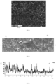
- FIG. 2 is a picture obtained by capturing the first region 30 and the second region 40 by using a scanning electron microscope (scanning electron microscope, SEM for short) with a magnification range of 50x to 5.0kx.
- the first region 30 and the second region 40 can be seen.
- the second region 40 is configured to cause adjacent first regions 30 to be spaced.
- the second region 40 is a channel for wetting the electrode plate, which helps improve a wetting effect of the electrode plate.
- An ultra-thin metallic lithium strip may be prepared by using an asynchronous rolling technology, a metallic lithium-containing region corresponding to the first region 30 and a metallic lithium-free region corresponding to the second region 40 are formed on a surface of the ultra-thin metallic lithium strip, and lithium ions in the metallic lithium strip are transferred to the first region 30, so that the first region 30 is formed on the surface of the first functional layer 20, and the second region 40 corresponds to the metallic lithium-free region.
- a width of the first region 30 ranges from 100 ⁇ m to 4 mm, that is, a spacing between two adjacent second regions 40 ranges from 100 ⁇ m to 4 mm.
- a spacing between two adjacent second regions 40 may be 100 ⁇ m, 1 mm, 2 mm, 3 mm, or 4 mm.
- a width of the second region 40 ranges from 0 ⁇ m to 4 mm, that is, a spacing between two adjacent first regions 30 ranges from 0 ⁇ m to 4 mm.
- second regions 40 and first regions 30 are alternately distributed, and widths of the second region 40 and the first region 30 are limited, which helps achieve a requirement on a surface density of supplemented lithium and improve uniformity of wetting the electrode plate by an electrolyte solution.
- a spacing between two adjacent first regions 30 may be 10 ⁇ m, 1 mm, 2 mm, 3 mm, or 4 mm.
- the lithium ions migrate to a region in which no lithium ions are embedded due to a concentration difference and a potential difference, so that a transition region 60 between the first region 30 and the second region 40 is formed, and lithium ions inside the first region 30 are uniformly distributed, to achieve a consistent lithium intercalation state, and avoid problems of lithium deposition and purple spots due to excessive local lithium ions, thereby improving overall uniformity of lithium intercalation.
- the electrode plate is supplemented with lithium by a process.
- the metallic lithium in the first region 30 reacts with silicon to generate a lithium silicate as a buffer layer, so as to alleviate expansion of the battery during a cycling process.
- a content ratio of the element oxygen to the element silicon in the first functional layer 20 located in the first region 30 is greater than 4:1.
- a content ratio S1:S2 of the element oxygen to the element silicon in the first functional layer 20 within the second region 40 satisfies: 2:1 ⁇ S1:S2 ⁇ 4:1.
- a content of the element oxygen in the first functional layer 20 located in the first region 30 is greater than a content of the element oxygen in the first functional layer 20 located in the second region 40.
- the SEI film In order to prevent silicon particles from rupturing during lithium intercalation, the SEI film repeatedly undergoes growth-rupture-repair. As a result, the SEI film accumulates in large quantities during a growth process, consuming lithium ions, and resulting in capacity fading, low initial efficiency, and poor cycling performance of the battery.
- the SEI film rich in inert substance LiF is constructed to improve stability of the SEI film, thereby improving cycling stability of the silicon negative electrode material.
- a content ratio of the element fluorine to the element phosphorus in the first functional layer 20 located in the first region 30 is greater than 7:1.
- a content ratio S3:S4 of the element fluorine to the element phosphorus in the first functional layer 20 located in the second region 40 satisfies: 6:1 ⁇ S3:S4 ⁇ 7:1.
- a content of the element fluorine in the first functional layer 20 located in the first region 30 is greater than a content of the element fluorine in the first functional layer 20 located in the second region 40.
- a content of the element phosphorus in the first functional layer 20 located in the first region 30 is greater than a content of the element phosphorus in the first functional layer 20 located in the first region 30.
- the present application further provides a battery, including a seal housing and an electrochemical cell located inside the seal housing, where the electrochemical cell includes a first electrode plate and a second electrode plate, and the first electrode plate is the electrode plate described above.
- active material particles of a first functional layer 20 include graphite and a silicon oxide material, and a mass proportion of the silicon oxide material may be 7% of a total mass of the active material particles.
- a surface density of metallic lithium contained in the first region 30 may be 0.12.
- a content ratio S1:S2 of an element oxygen to an element silicon within the first region 30 is 5:1, and a content ratio S3: S4 of an element fluorine to an element phosphorus within the first region 30 is 7:1.
- a content ratio S1:S2 of the element oxygen to the element silicon within the second region 40 is 4:1, and a content ratio S3:S4 of the element fluorine to the element phosphorus within the second region 40 is 6:1.
- active material particles of a first functional layer 20 include graphite and a silicon oxide material, and a mass proportion of the silicon oxide material may be 20% of a total mass of the active material particles.
- a surface density of metallic lithium contained in the first region 30 may be 0.22.
- a content ratio S1:S2 of an element oxygen to an element silicon within the first region 30 is 6:1, and a content ratio S3:S4 of an element fluorine to an element phosphorus within the first region 30 is 7.5:1.
- a content ratio S1 :S2 of the element oxygen to the element silicon within the second region 40 is 4:1, and a content ratio S3:S4 of the element fluorine to the element phosphorus within the second region 40 is 6:1.
- active material particles of a first functional layer 20 include graphite and a silicon oxide material, and a mass proportion of the silicon oxide material may be 30% of a total mass of the active material particles.
- a surface density of metallic lithium contained in the first region 30 may be 0.32.
- a content ratio S1:S2 of an element oxygen to an element silicon within the first region 30 is 7:1, and a content ratio S3:S4 of an element fluorine to an element phosphorus within the first region 30 is 8:1.
- a content ratio S1:S2 of the element oxygen to the element silicon within the second region 40 is 4:1, and a content ratio S3:S4 of the element fluorine to the element phosphorus within the second region 40 is 6:1.
- active material particles of a first functional layer 20 include graphite and a silicon oxide material, and a mass proportion of the silicon oxide material may be 40% of a total mass of the active material particles.
- a surface density of metallic lithium contained in the first region 30 may be 0.42.
- a content ratio S1:S2 of an element oxygen to an element silicon within the first region 30 is 8:1, and a content ratio S3:S4 of an element fluorine to an element phosphorus within the first region 30 is 8.5:1.
- a content ratio S1 :S2 of the element oxygen to the element silicon within the second region 40 is 4:1, and a content ratio S3:S4 of the element fluorine to the element phosphorus within the second region 40 is 6:1.
- active material particles of a first functional layer 20 include graphite and a silicon oxide material, and a mass proportion of the silicon oxide material may be 50% of a total mass of the active material particles.
- a surface density of metallic lithium contained in the first region 30 may be 0.5.
- a content ratio S1:S2 of an element oxygen to an element silicon within the first region 30 is 9:1, and a content ratio S3:S4 of an element fluorine to an element phosphorus within the first region 30 is 9:1.
- a content ratio S1:S2 of the element oxygen to the element silicon within the second region 40 is 4:1, and a content ratio S3:S4 of the element fluorine to the element phosphorus within the second region 40 is 6:1.
- the active material particles in the first functional layer 20 include the graphite and the silicon oxide material
- the mass of the silicon oxide material may account for 7% to 50% of the total mass of the active material particles
- the graphite may be artificial graphite, natural graphite, or modified graphite
- the surface density of the metallic lithium contained in the first region 30 ranges from 0.09 mg/cm 2 to 0.5 mg/cm 2 . In this way, an amount of the metallic lithium matches an amount of the silicon particles. If the amount of the metallic lithium is too large, lithium ions react with the electrolyte solution and deposition occurs, reducing utilization of lithium ions. If the amount of the metallic lithium is too small, a lithium supplementation effect is not noticeable, and accordingly improvement in initial efficiency is not noticeable.
- active material particles of a first functional layer 20 include graphite and a silicon oxide material, and a mass proportion of the silicon oxide material may be 7% of a total mass of the active material particles.
- a surface density of metallic lithium contained in the first region 30 may be 0.18.
- a content ratio S1:S2 of an element oxygen to an element silicon within the first region 30 is 6:1, and a content ratio S3:S4 of an element fluorine to an element phosphorus within the first region 30 is 7:1.
- a content ratio S1:S2 of the element oxygen to the element silicon within the second region 40 is 4:1, and a content ratio S3:S4 of the element fluorine to the element phosphorus within the second region 40 is 6:1.
- active material particles of a first functional layer 20 include graphite and a silicon oxide material, and a mass proportion of the silicon oxide material may be 30% of a total mass of the active material particles.
- a surface density of metallic lithium contained in the first region 30 may be 0.28.
- a content ratio S1:S2 of an element oxygen to an element silicon within the first region 30 is 7.5: 1
- a content ratio S3:S4 of an element fluorine to an element phosphorus within the first region 30 is 8:1.
- a content ratio S1:S2 of the element oxygen to the element silicon within the second region 40 is 4:1, and a content ratio S3: S4 of the element fluorine to the element phosphorus within the second region 40 is 6:1.
- active material particles of a first functional layer 20 include graphite and a silicon oxide material, and a mass proportion of the silicon oxide material may be 50% of a total mass of the active material particles.
- a surface density of metallic lithium contained in the first region 30 may be 0.34.
- a content ratio S1:S2 of an element oxygen to an element silicon within the first region 30 is 8:1, and a content ratio S3:S4 of an element fluorine to an element phosphorus within the first region 30 is 8.5:1.
- a content ratio S1 :S2 of the element oxygen to the element silicon within the second region 40 is 4:1, and a content ratio S3:S4 of the element fluorine to the element phosphorus within the second region 40 is 6:1.
- the active material particles in the first functional layer 20 include the graphite and the silicon oxide material
- the mass of the silicon oxide material may account for 7% to 50% of the total mass of the active material particles
- the surface density of the metallic lithium contained in the first region 30 ranges from 0.09 mg/cm 2 to 0.5 mg/cm 2 .
- an amount of the metallic lithium matches an amount of the silicon particles. This avoids a reaction between lithium and the electrolyte solution and occurrence of deposition caused due to excessive metallic lithium, and accordingly reducing utilization of lithium ions, and avoids an unnoticeable lithium supplementation effect and unnoticeable improvement in initial efficiency caused due to a too small amount of metallic lithium.
- the first current collector 10 is placed in a dry environment at a temperature of 90°C and baked for 24 hours to control a moisture content below 300 ppm to obtain a semi-finished electrode plate. Then, an ultra-thin metallic lithium strip is prepared by using an asynchronous rolling technology and laminated with the semi-finished electrode plate to prepare an electrode plate.
- the present application further provides a battery, including a seal housing and an electrochemical cell located inside the seal housing, where the electrochemical cell includes a first electrode plate and a second electrode plate, and the first electrode plate is the electrode plate described above.
- the second electrode plate is a positive electrode plate
- the first electrode plate is a negative electrode plate
- the first electrode plate, the second electrode plate, and a separator are stacked in sequence so that the separator is located between the first electrode plate and the second electrode plate, where the separator serves to separate the first electrode plate from the second electrode plate. Then, the first electrode plate, the second electrode plate, and the separator electrochemical cell are wound to obtain an electrochemical cell, the electrolyte solution is placed in a seal housing, an electrolyte solution is injected into the seal housing.
- the electrochemical cell After vacuum packaging, standing, and formation, the electrochemical cell is charged at a constant current of 0.1C to a state of charge (State of Charge, SOC for short) of 4%, and then charged at a constant current of 0.2C to a SOC of 10%, and processes such as shaping and capacity testing are performed, to obtain a soft-pack lithium-ion battery.
- SOC state of Charge
- the seal housing may be an aluminum-plastic film
- the electrolyte solution may include lithium hexafluorophosphate
- the first region 30 is a supplemented lithium region
- the second region 40 is a non-supplemented-lithium region. According to a 3D microscope test, the first region 30 is brighter, and the second region 40 is darker (as shown in FIG. 14 ).
- lithium supplementation may be performed according to the following process: As shown in FIG. 15 , a plurality of lithium strips 80 are alternately distributed on a surface of a first functional layer 20, and there are gaps C between the plurality of lithium strips 80 that expose the surface of the first functional layer 20. After reactions, such as formation, during a battery preparation process, a region on which the lithium strip 80 is disposed forms a supplemented lithium region, namely, the first region 30. The gap C between the plurality of lithium strips 80 forms a non-supplemented-lithium region, namely, the second region 40. As shown in FIG. 14 , the first region 30 is in a discontinuous state. The second region 40 facilitates wettability of the electrolyte solution for the electrode plate, to improve utilization of the lithium strips and optimize performance of the electrode plate and the battery.
- an electrode plate precursor having the first functional layer 20 formed thereon may be baked at about 90°C for about 24 hours in a dry environment to control a moisture content below 300 ppm, and then the lithium strips 80 are placed on a surface of the baked electrode plate, and after processing such as lamination, the lithium strips 80 is laminated with the first functional layer 20 for lithium supplementation.
- the foregoing electrode plate may be prepared by using a coating method, and its preparation process generally includes steps such as material preparation (preparing a slurry), coating (coating the slurry on a surface of a current collector substrate to form the first functional layer 20), rolling, slitting (slitting according to parameters such as a preset size and a shape of the electrode plate), baking, and then subsequent processes such as lithium supplementation are performed.
- the lithium strip 80 used may include a short lithium strip having a length less than a width of the first functional layer 20 (distribution of short lithium strips is shown in FIG. 15 , and a surface morphology of the electrode plate formed is shown in FIG. 14 ), and a plurality of short lithium strips may be placed in sequence along a width direction of the first functional layer 20 (a direction indicated by arrow B) to form a column.
- another column may be formed along a length direction of the first functional layer 20 (a direction indicated by arrow A), and a length of each column may be less than or equal to a width of the electrode plate (a length of the column formed by arrangement of the first region 30 is less than or equal to the width of the electrode plate).
- a plurality of short lithium strips may alternatively be irregularly distributed on the surface of the first functional layer 20, or long lithium strips having a length substantially the same as the width of the first functional layer 20 may be spaced and distributed on the surface of the first functional layer 20 (for example, there is a gap between any two adjacent long lithium strips, and after formation, the gap forms the second region 40).
- an amount of the lithium strips 80 used may satisfy the following: a ratio of a total mass of the lithium strips 80 disposed on the surface of the first functional layer 20 to an area of the surface of the first functional layer 20 (a surface away from the first current collector 10) ranges from 0.09:1 to 0.5:1 (mg:m 2 ).
- a thickness of the lithium strip 80 may range from 1.9 ⁇ m to 9 ⁇ m. Due to an extremely high theoretical specific capacity of pure metallic lithium, if an entire surface of the electrode plate is supplemented with lithium, a thickness of the metallic lithium usually needs to be about 1 ⁇ m, which is extremely difficult to prepare and has poor consistency.
- ultra-thin metallic lithium strips are used for non-full-surface lithium supplementation. The ultra-thin metallic lithium strips present a non-continuous coverage state such as stripes/ripples on the surface of the first functional layer 20, which can effectively achieve lithium supplementation and improve utilization of metallic lithium while having advantages such as simple preparation and good consistency.
- a lithium ingot is generally pressed to a thickness at a micrometer level, and then an obtained micrometer-level lithium strip is placed on the surface of the first functional layer 20 for lithium supplementation.
- a lithium ingot with a thickness of 200 ⁇ m to 2 mm is pressed to form a lithium strip 80 with a thickness of 1.9 ⁇ m to 9 ⁇ m, which is then placed on the surface of the first functional layer 20 for lithium supplementation.
- an inorganic salt layer may be an inorganic salt layer formed by embedding a lithium source obtained through lithium supplementation into active material particles in the first region 30, that is, a material included in the inorganic salt layer is an inorganic salt, and the inorganic salt layer is generated by embedding the element lithium supplemented in the first region 30 into the active material particles in the first region 30.
- the inorganic salt layer includes, for example, at least one of lithium fluoride, lithium carbonate, lithium silicate, and the like.
- first regions 30 and second regions 40 are alternately distributed/distributed at intervals, that is, a plurality of first regions 30 and a plurality of second regions 40 are distributed on the surface of the first functional layer 20, and the plurality of second regions 40 separate the surface of the first functional layer 20 to form the plurality of first regions 30.
- the plurality of first regions 30 may be distributed along the length direction of the first functional layer 20/the electrode plate (a direction indicated by arrow A), that is, the plurality of first regions 30 and the plurality of second regions 40 are alternately distributed in sequence along the length direction of the first functional layer 20/the electrode plate.
- a first angle may be formed between an extension direction/a length direction of the first region 30 and the width direction of the first functional layer 20, and the first angle may range from 0° to 60°.
- the first angle may range from 0° to 45°, and for example, is 0° (that is, the length direction of the first region 30 is parallel to the width direction of the first functional layer 20), 10°, 20°, 30°, 40° or 45°, or the like. This facilitates lithium supplementation for the electrode plate and wetting of the electrolyte solution while not affecting winding of the electrode plate along its length direction, which is beneficial to manufacturing and performance of the battery.
- Extension directions of the plurality of first regions 30 may be the same or different, that is, first angles formed between the extension directions and the width direction of the first functional layer 20 may be the same or different.
- a distance between a first region 30 closest to an outer edge/edge of the first functional layer 20 and the outer edge of the first functional layer 20 is A, and A may range from 0 mm to 2 mm, and for example, is 0 (that is, the first region 30 is flush with the outer edge of the first functional layer 20), 0.5 mm, 1 mm, 1.5 mm, 2 mm, or the like.
- a ratio of A to the width of the first functional layer 20 may range from 0 to 0.03, and for example, is 0, 0.01, 0.02, 0.03, or the like.
- a column in the width direction of the first functional layer 20, a column is formed by at least one first region 30.
- the column may be in a continuous state, that is, the column is formed by one first region 30 (the column is not spaced by the second region 40).
- the column may be in a discontinuous state, that is, the column is formed by a plurality of first regions 30 arranged in sequence along the width direction of the first functional layer 20, where the second region 40 exists between two adjacent first regions 30, which are spaced by the second region 40.
- the first region 30 extends along the width direction of the first functional layer 20.
- the first region 30 may be a substantially straight structure, or may have a bent/curved structure or the like.
- a distance between a first region 30 closest to an outer edge of the first functional layer 20 and the outer edge of the first functional layer 20 may range from 0 mm to 4 mm, for example, ranges from 100 ⁇ m to 4 mm.
- the first functional layer 20 has a first end and a second end opposite to each other, and a direction from the first end to the second end is parallel to the length direction of the first functional layer 20, and a distance w1 between a first region 30 closest to a first end and an edge of the first end of the first functional layer 20 (an edge of the first functional layer 20) ranges from 100 ⁇ m to 4 mm, and for example, is 100 ⁇ m, 300 ⁇ m, 500 ⁇ m, 700 ⁇ m, 1 mm, 2 mm, 3 mm, 4 mm, or the like.
- a width of a second region 40 existing between the first region 30 closest to the first end and the edge of the first end is w1.
- a distance w2 between a first region 30 closest to a second end (an edge of the first functional layer 20) and the edge of the second end of the first functional layer 20 ranges from 0 ⁇ m to 4 mm, and for example, is 0, 100 ⁇ m, 300 ⁇ m, 500 ⁇ m, 700 ⁇ m, 1 mm, 2 mm, 3 mm, 4 mm, or the like.
- w1 and w2 may be the same or different.
- a ratio of a total area of the plurality of first regions 30 (that is, a sum of areas of the plurality of first regions 30) to a total area of the plurality of second regions 40 ranges from 0.7:1 to 3:1, and for example, is 0.7:1, 1:1, 1.5:1, 2:1, 2.5:1, 3:1, or the like.
- a microscope may be used to capture contours of the first regions 30 and the second regions 40 to measure the ratio of the total area of the plurality of first regions 30 to the total area of the plurality of second regions 40.
- the first region 30 is higher than the second region 40, that is, in the thickness direction of the first functional layer 20, a distance a between a portion, farthest from the first current collector 10, of the first region 30 and the first current collector 10 is greater than a distance b between a portion, farthest from the first current collector 10, of the second region 40 and the first current collector 10 (a> b).
- a height difference between the portion, farthest from the first current collector 10, of the first region 30 and the portion, farthest from the first current collector 10, of the second region 40 ranges from 0.1 ⁇ m to 8 ⁇ m (that is, a-b ranges from 0.1 ⁇ m to 8 ⁇ m), and for example, is 0.1 ⁇ m, 0.5 ⁇ m, 1 ⁇ m, 2 ⁇ m, 3 ⁇ m, 4 ⁇ m, 5 ⁇ m, 6 ⁇ m, 7 ⁇ m, 8 ⁇ m, or the like.
- manners of measuring a height difference between the first region 30 and the second region 40 include but are not limited to: (1) sputtering the lithium-supplemented electrode plate by using a Cross-section Polisher (CP), to obtain a cross section, photographing the cross section by using a scanning electron microscope (SEM), and zooming in the cross section to a desired magnification for photographing, to obtain the height difference; and (2) using a 3D microscope to zoom in the cross section to a desired magnification for photographing, and then measuring the height difference by using a profilometer.
- CP Cross-section Polisher
- SEM scanning electron microscope
- the first functional layer 20 is provided with a first groove 21, and a first adhesive layer 81 covers the first groove 21.
- the first groove 21 may be used as a tab groove for disposing a tab.
- the electrode plate further includes a first tab 91 and a first adhesive layer 81 formed on the surface of the first functional layer 20, and at least a part of the first tab 91 is located in the first groove 21 and is covered by the first adhesive layer 81 (that is, a part, located in the first groove 21, of the first tab 91 is covered by the first adhesive layer 81). In this way, a tab region can be protected and safety of the electrode plate and the battery can be improved.
- this prevents lithium in a supplemented lithium region around the first tab from migrating to a positive tab region (corresponding to a tab groove in which a positive tab is located) during a charge-discharge process, and prevents a lithium deposition problem in a negative tab region accordingly caused.
- the first adhesive layer 81 is disposed on a partial region of the surface of the first functional layer 20, that is, does not completely cover the first functional layer 20.
- the first adhesive layer 81 covers at least one first region 30.
- At least a part of a bottom surface of the first groove 21 is a surface of the first current collector 10, that is, a part of the bottom surface of the first groove 21 exposes the first current collector 10, and the first electrode tab 91 may be connected to the first current collector 10 exposed on the bottom surface of the first groove 21, and specifically may be welded to the first current collector 10 exposed on the bottom surface of the first groove 21.
- the electrode plate may be of a center-pull tab (CPT) structure, that is, the tab is disposed in the middle of the electrode plate, rather than at an end.
- CPT center-pull tab
- the first groove 21 are the first functional layer 20.
- one side of the first groove 21 is flush with one long side of the first current collector 10, and other sides are surrounded by the first functional layer 20, that is, the first groove 21 has an opening facing one long side of the first current collector 10.
- one end of the first tab 91 may extend out of the outer edge of the first current collector 10 through the opening.
- the first tab 91 may extend out of the outer edge of the first current collector 10 through the opening along its length direction.
- a part, located in the first groove 21, of the first tab 91 (that is, a part that does not extend out of the outer edge of the first current collector 10) is covered by the first adhesive layer 81 (as shown in FIG. 12 ).
- the length direction of the first electrode tab 91 is parallel to a length direction of the first region 30/the second region 40 (that is, the first tab 200 and the first region 30/the second region 40 extend in a same direction).
- a projection of the first groove 21 onto the first current collector 10 is a rectangle, one short side of which is flush with one long side of the first current collector 10, and the other three sides are surrounded by the first functional layer 20.
- the first groove 21 has a first side and a second side opposite to each other, and a third side and a fourth side opposite to each other, the third side/the fourth side is located between the first side and the second side (the third side/fourth side connects the first side and the second side), and a direction from the first side to the second side is parallel to a direction from the first region to the second region.
- the first side is the left side
- the second side is the right side
- the third side is the lower side
- the fourth side is the upper side.
- the left side, right side, and lower side of the first groove 21 are all surrounded by the first functional layer 20, and there is no first functional layer 20 on the upper side (that is, the upper side of the first groove 21 is flush with an edge of the first functional layer 20).
- the direction from the first side to the second side is parallel to the length direction of the first functional layer 20, and the direction from the third side to the fourth side is parallel to the width direction of the first functional layer 20.
- the first adhesive layer 81 extends to a surface, around the first groove 21, of the first functional layer 20.
- a part of the first adhesive layer 81 that is located on a surface, on the first side of the first groove 21, of the first functional layer 20 covers a1 first regions 30, where a1 ranges from 0 to 8, and for example, is 0, 1, 2, 3, 4, 5, 6, 7, 8, or the like.
- a quantity of first regions located on the first side of the first groove 21 and in contact with the first adhesive layer 81 is a1
- the surface of the first functional layer 20 includes a third region 85 located on the first side of the first groove 21 and covered by the first adhesive layer 81, and a quantity of first regions 30 extending into the third region 85 is a1.
- a1 1.
- a part of the first adhesive layer 81 that is located on a surface, on the second side of the first groove 21, of the first functional layer 20 covers a2 first regions 30, where a2 ranges from 0 to 8.
- a quantity of first regions 30 located on the second side of the first groove 21 and in contact with the first adhesive layer 81 is a2
- the surface of the first functional layer 20 includes a fourth region 86 located on the second side of the first groove 21 and covered by the first adhesive layer 81, and a quantity of first regions 30 extending into the fourth region 86 is a2.
- a2 1.
- a part of the first adhesive layer 81 that is located on a surface, on the third side of the first groove 21, of the first functional layer 20 is in contact with a3 first regions 30, where a3 ranges from 0 to 40, and for example, is 0, 2, 5, 8, 10, 12, 15, 18, 20, 22, 25, 28, 30, 32, 35, 38, 40, or the like.
- a quantity of first regions 30 located on the third side of the first groove 21 and in contact with the first adhesive layer 81 is a3, that is, the surface of the first functional layer 20 includes a fifth region 87 located on the third side of the first groove 21 and covered by the first adhesive layer 81, and a quantity of first regions 30 extending into the fifth region 87 is a3.
- a3 is also a total quantity of first regions 30 in contact with the first adhesive layer 81.
- first regions 30 (a1) extending into the third region 85 all extend into the fifth region 87
- first regions 30 (a2) extending into the fourth region 86 all extend into the fifth region 87.
- the part of the first adhesive layer 81 on the surface, located on the first side of the first groove 21, of the first functional layer 20 has a width w31 ranging from 1 mm to 5 mm in the length direction of the first functional layer 20 (that is, a width of the third region 85 in the length direction of the first functional layer 20), for example, 1 mm, 1.5 mm, 2 mm, 2.5 mm, 3 mm, 3.5 mm, 4 mm, 4.5 mm, 5 mm, or the like.
- the part of the first adhesive layer 81 on the surface, located on the second side of the first groove 21, of the first functional layer 20 has a width w32 ranging from 1 mm to 5 mm in the length direction of the first functional layer 20 (that is, a width of the fourth region 86 in the length direction of the first functional layer 20), for example, 1 mm, 1.5 mm, 2 mm, 2.5 mm, 3 mm, 3.5 mm, 4 mm, 4.5 mm, 5 mm, or the like.
- w31 and w32 may be the same or different.
- a total width of the first adhesive layer 81 in the length direction of the first functional layer 20 is substantially equal to a sum of w31, a width of the first groove 21 in the length direction of the first functional layer 20, and w32.
- end edges of two opposite ends of the first region 30 are respectively flush with edges of two opposite sides of the first functional layer 20.
- a length of any first region 30 in the width direction of the first functional layer 20 is equal to a length of the first functional layer 20 at which the first region 30 is located.
- a length of first regions 30 located on the two opposite sides (the first side and the second side) of the first groove 21 is equal to a width of a part of the first functional layer 20 located on the two opposite sides of the first groove 21.
- the length direction of the first functional layer 20 is also the length direction of the first current collector 10, and the width direction of the first functional layer 20 is also the width direction of the first current collector 10.
- the width of the first current collector 10 is substantially equal to a maximum width of the first functional layer 20 (that is, the width of the first functional layer 20 in FIG. 11 and FIG. 12 located on two opposite sides of the first groove 21).
- At least one end portion of the first current collector 10 may be further provided with a first foil uncoating region 11 in which no first functional layer 20 is disposed.
- An embodiment of the present application further provides a battery, including a first electrode plate, a separator, and a second electrode plate having a polarity opposite to that of the first electrode plate, which are stacked in sequence.
- the first electrode plate includes the electrode plate described above.
- the battery includes an electrochemical cell.
- the electrochemical cell includes a first electrode plate, a separator, and a second electrode plate stacked in sequence.
- the electrochemical cell may be specifically a wound electrochemical cell formed by stacking the first electrode plate, the separator, and the second electrode plate in sequence and then winding them, where the winding may be performed along a length direction of the first electrode plate/the separator/the second electrode plate to form a wound electrochemical cell.
- the first electrode plate, the separator, and the second electrode plate each have a bending portion, and straight portions connected to both ends of each bending portion. A direction from one bending portion to another bending portion is parallel to a length direction of the wound electrochemical cell, and a direction from one straight portion to another straight portion is parallel to a width direction of the wound electrochemical cell.
- the separator severs to separate the first electrode plate and the second electrode plate to prevent them from coming into contact with each other and short-circuiting.
- a thickness of the separator may range from 5 ⁇ m to 16 ⁇ m, and for example, is 5 ⁇ m, 8 ⁇ m, 10 ⁇ m, 13 ⁇ m, 16 ⁇ m, or the like.
- the separator may be a conventional separator in the art, and for example, includes a substrate or a coating separator with a coating on a substrate
- the second electrode plate includes a second current collector and a second functional layer 92 disposed on a surface of the second current collector.
- the second electrode plate has two opposite ends (denoted as a fifth end and a sixth end, respectively), and at least one end thereof has a second foil uncoating region 93 without a coating. Except for the second foil uncoating region 93, the rest of the second electrode plate is provided with the second functional layer 92. A part at which the second functional layer 92 and the second foil uncoating region 93 are connected usually has an uneven structure.
- a second adhesive layer 82 may be disposed on a part that is on at least one end of the second electrode plate and that is covered by the first electrode plate.
- the part, covered by the first electrode plate, of the second electrode plate is usually also a part, covered by the separator, of the second electrode plate.
- the second functional layer 92 is an active material layer of the second electrode plate.
- a second adhesive layer 82 is disposed on a region that is on at one end (the fifth end) of the second electrode plate and that is covered by the first electrode plate, and a quantity of first regions 30 of the first electrode plate that correspond to the second adhesive layer 82 is x, where 0 ⁇ x ⁇ 20, and x is, for example, 0, 1, 2, 3, 4, 5, 6, 7, 8, 9, 10, 11, 12, 13, 14, 15, 16, 17, 18, 19, or 20.
- the first electrode plate has two opposite ends (denoted as a third end and a fourth end, respectively), and one end (the third end) thereof has a first end covering region 22.
- the first end covering region 22 corresponds to a position of the second adhesive layer 82 of the second electrode plate, that is, the first end covering region 22 and the second adhesive layer 82 cover each other (a projection of the second adhesive layer 82 onto the first electrode plate basically coincides with the first end covering region 22).
- a width w4 of the first end covering region 22 in the length direction of the first electrode plate/the second electrode plate is equal to a width w6 of the second adhesive layer 82 in the length direction of the first electrode plate/the second electrode plate.
- the width w6 of the second adhesive layer 82 in the length direction of the second electrode plate ranges from 3 mm to 5 mm, and w6 is, for example, 3 mm, 3.5 mm, 4 mm, 4.5 mm, 5 mm, or the like.
- the second adhesive layer 82 covers at least a part of the second foil uncoating region 93, and extends from the second foil uncoating region 93 to the surface of the second functional layer 92.
- the other end (the fourth end) of the first electrode plate has a second end covering region 23 covering the other end (the sixth end) of the second electrode plate, that is, a projection of the sixth end of the second electrode plate onto the first electrode plate is located in the second end covering region 23 and does not go beyond the second end covering region 23.
- There is no foil uncoating region on the sixth end of the second electrode plate that is, the second functional layer 92 is flush with an outer edge of the second current collector), and the second adhesive layer 82 may not be disposed.
- a width w5 of the second end covering region 23 in the length direction of the first electrode plate ranges from 3 mm to 5 mm, and for example, is 3 mm, 3.5 mm, 4 mm, 4.5 mm, 5 mm, or the like.
- a third adhesive layer corresponding to a position of the first tab 91/the first groove 21 of the first electrode plate is disposed on the surface of the second electrode plate.
- a projection of the third adhesive layer onto the first electrode plate may cover the first groove 21 to further prevent lithium deposition at a negative electrode.
- a first projection of the third adhesive layer onto the first electrode plate covers at least one first region 30 and satisfies the following: a part of the first projection located on the first side of the first groove 21 covers 0 to 8 first regions 30, for example, covers 0, 1, 2, 3, 4, 5, 6, 7, or 8 first regions 30, a quantity of which may be equal to or not equal to a1; a part of the first projection located on the second side of the first groove 21 covers 0 to 8 first regions 30, for example, covers 0, 1, 2, 3, 4, 5, 6, 7, or 8 first regions 30, a quantity of which may be equal to or not equal to a2; and a part of the first projection located on the third side of the first groove 21 covers 0 to 40 first regions 30, for example, covers 0, 2, 5, 8, 10, 12, 15, 18, 20, 22, 25, 28, 30, 32, 35, 38, or 40 first regions 30, a quantity of which may be equal to or not equal to a3.
- the part of the first projection located on the first side of the first groove 21 has a width ranging from 1 mm to 5 mm in the length direction of the first functional layer 20, for example, 1 mm, 1.5 mm, 2 mm, 2.5 mm, 3 mm, 3.5 mm, 4 mm, 4.5 mm, 5 mm, or the like, where the width may be equal to or not equal to w31; and the part of the first projection located on the second side of the first groove 21 has a width ranging from 3 mm to 5 mm in the length direction of the first functional layer 20, for example, 1 mm, 1.5 mm, 2 mm, 2.5 mm, 3 mm, 3.5 mm, 4 mm, 4.5 mm, 5 mm, or the like, where the width may be equal to or not equal to w32.
- the first projection of the third adhesive layer onto the first electrode plate may cover the first adhesive layer 81, or be covered by the first adhesive layer 81, and for example, the two may coincide with each other.
- the second electrode plate is provided with a second tab, and in a width direction of the electrochemical cell, the first tab 91 does not overlap the second tab. That is, a projection of the first tab 91 perpendicular to a width direction of the electrochemical cell does not overlap a projection of the second tab perpendicular to the width direction of the electrochemical cell.
- the second functional layer 92 is provided with a second groove 921 and a fourth adhesive layer 84 covering the second groove 921, and the second tab is at least partially located in the second groove 921 and is covered by the fourth adhesive layer 84 (that is, a part, located in the second groove 921, of the second tab is covered by the second adhesive layer 82).
- the second groove 921 serves as a tab groove for disposing a tab
- at least a part of a bottom surface of the second groove 921 is a surface of the second current collector (that is, a part of the bottom surface of the second groove 921 exposes the second current collector)
- the second tab may be connected to the second current collector exposed on the bottom surface of the second groove 921, and specifically may be welded to the second current collector exposed on the bottom surface of the second groove 921.
- the second electrode plate may be of a center-pull tab structure, that is, the second tab is disposed in the middle of the second electrode plate, rather than at an end.
- the second groove 921 are the second functional layer 92.
- one side of the second groove 921 is flush with one long side of the second current collector, and other sides are surrounded by the second functional layer 92, that is, the second groove 921 has an opening facing one long side of the second current collector.
- one end of the second tab may extend out of the outer edge of the second current collector through the opening.
- the second tab may extend out of the outer edge of the second current collector through the opening along its length direction.
- a part, located in the second groove 921, of the second tab (that is, a part that does not extend out of the outer edge of the first current collector 10) is covered by the second adhesive layer 82.
- a length direction of the second tab is parallel to a width direction of the second electrode plate.
- a projection of the second groove 921 onto the second current collector is a rectangle, one short side of which is flush with one long side of the second current collector, and the other three sides are surrounded by the second functional layer.
- the fourth adhesive layer 84 extends to a surface of the second functional layer 92 around the second groove 921 and is bonded to the second functional layer 92 around the second groove 921.
- the second groove 921 has a fourth side, a fifth side, and a sixth side, and a direction from the fourth side to the fifth side is parallel to the length direction of the second electrode plate.
- a projection of the fourth adhesive layer 84 onto the first electrode plate covers at least one first region 30 and satisfies the following: a projection of a part, located on the fourth side of the second groove, of the fourth adhesive layer 84 onto the first electrode plate covers 0 to 8 first regions 30, for example, covers 0, 1, 2, 3, 4, 5, 6, 7 or 8 first regions 30, a quantity of which may be equal to or not equal to a1; a projection of a part, located on the fifth side of the second groove, of the fourth adhesive layer 84 onto the first electrode plate covers 0 to 8 first regions 30, for example, covers 0, 1, 2, 3, 4, 5, 6, 7 or 8 first regions 30, a quantity of which may be equal to or not equal to a2; and a projection of a part, located on the sixth side of the second groove, of the fourth adhesive layer 84 onto the first
- the part, located on the fourth side of the second groove, of the fourth adhesive layer 84 may have a width ranging from 1 mm to 5 mm in the length direction of the second electrode plate, for example, 1 mm, 1.5 mm, 2 mm, 2.5 mm, 3 mm, 3.5 mm, 4 mm, 4.5 mm, 5 mm, or the like, where the width may be equal to or not equal to w31; and
- the part, located on the fifth side of the second groove, of the fourth adhesive layer 84 may have a width ranging from 3 mm to 5 mm in the length direction of the second electrode plate, for example, 1 mm, 1.5 mm, 2 mm, 2.5 mm, 3 mm, 3.5 mm, 4 mm, 4.5 mm, 5 mm, or the like, where the width may be equal to or not equal to w32.
- parameters such as a shape and a size of the second groove 921 may be the same as or different from those of the first groove 21, and parameters such as a shape and an area of the fourth adhesive layer 84 may be the same as or different from those of the first adhesive layer 81.
- Thicknesses of the first adhesive layer 81, the second adhesive layer 82, the third adhesive layer, and the fourth adhesive layer 84 each may range from 10 ⁇ m to 16 ⁇ m, and for example, is 10 ⁇ m, 11 ⁇ m, 12 ⁇ m, 13 ⁇ m, 14 ⁇ m, 15 ⁇ m, 16 ⁇ m, or the like.
- the first adhesive layer 81, the second adhesive layer 82, the third adhesive layer, and the fourth adhesive layer 84 may be specifically made of adhesive tape.
- a specific adhesive layer covers the first region 30 as described above means that, in the length direction of the first functional layer 20, two opposite sides of the first region 30 covered by the adhesive layer are both located within the projection of the adhesive layer onto the surface of the first functional layer 20 (that is, the first region 30 covered by the adhesive layer does not extend out of an outer edge of the projection of the adhesive layer onto the surface of the first functional layer 20), and in the width direction of the first functional layer 20, the first region 30 covered by the adhesive layer may be partially located within the projection of the adhesive layer onto the surface of the first functional layer 20, and partially located outside the projection of the adhesive layer onto the surface of the first functional layer 20, or entirely located within the projection of the adhesive layer onto the surface of the first functional layer 20.
- the first adhesive layer 81 covers four first regions 30, and in the length direction of the first functional layer 20, two opposite sides of each of the four first regions 30 are both located within the projection of the first adhesive layer 81 onto the surface of the first functional layer 20; and in the width direction of the first functional layer 20, the four first regions 30 partially extend into the projection of the first adhesive layer 81 onto the surface of the first functional layer 20, and partially are located outside the projection of the first adhesive layer 81 onto the surface of the first functional layer 20.
- the battery described above may include a lithium-ion battery, which may be prepared by using a conventional method in the art.
- a preparation process generally includes steps of winding, packaging, liquid injection, aging, formation, secondary sealing, sorting, packing, and the like.
- the first electrode plate, the separator, and the second electrode plate may be stacked and placed, and then wound to form a bare electrochemical cell, and the bare electrochemical cell is placed in an outer packaging foil (such as an aluminum-plastic film).
- an electrolyte solution is injected into the electrochemical cell, and then the electrochemical cell is made into a soft-pack lithium-ion battery through processes such as vacuum packaging, standing, formation (for example, charging at a 0.1C constant current to a SOC (state of charge) of 4%, and then charging at a 0.2C constant current to a SOC of 10%), and shaping.
- Test 1 Surface morphology test of a first region 30 and a second region 40
- a scanning electron microscope (SEM) was used for photographing with a magnification range of 500x to 1.0kx.
- FIG. 2 is a SEM image captured at a magnification of 50x. Widths of the first region 30 and the second region 40 were measured by using a ruler.
- Test 2 Element test of a first region 30 and a second region 40
- an electrode plate provided in an embodiment of the present application was selected.
- a position at which a SEM image was captured was further analyzed by using an X-ray energy dispersive spectrometer (Energy Dispersive Spectrometer, EDS for short).
- EDS X-ray energy dispersive spectrometer
- FIG. 3 which is an EDS area scan image of a 500x SEM image.
- FIG. 4 which is an EDS area scan image of a 500x SEM image at a dashed line position within a dotted box in FIG. 3 .
- the horizontal line AB shown in FIG. 5 represents a linear path position extending from the first region 30 to the second region 40.
- An X-ray Energy Dispersive Spectrometer (EDS) analysis was used to measure element distribution at a position of the horizontal line AB shown in FIG. 5 .
- EDS X-ray Energy Dispersive Spectrometer
- FIG. 6 is a distribution trend diagram of a phosphorus element, where a horizontal axis represents a position and a vertical axis represents a content of the phosphorus element. It can be learned from FIG. 6 that the content of the element phosphorus decreases from the first region 30 to the second region 40.
- FIG. 7 is a distribution trend diagram of a fluorine element, where a horizontal axis represents a position and a vertical axis represents a content of the fluorine element. It can be learned from FIG. 7 that the content of the element fluorine decreases from the first region 30 to the second region 40.
- FIG. 8 is a distribution trend diagram of an element oxygen, where a horizontal axis represents a position and a vertical axis represents a content of the element oxygen. It can be learned from FIG. 8 that the content of the element oxygen decreases from the first region 30 to the second region 40.
- Test 3 Cycling test and expansion test
- a testing process includes the following steps:
- Step 9 Repeating step 8 and step 9 for 1000 cycles, where in cycles 0 to 200, after every 50 cycles, testing the thickness of the battery in a fully charged state; in cycles 200 to 1000, after every 100 cycles, testing the thickness of the battery in a fully charged state, and repeating step 3 and step 4 to conduct a capacity test in a temperature environment of 25°C; and after 1000 cycles, testing the thickness of the battery in a fully charged state.
- Batteries with a same target capacity and different surface densities of supplemented lithium were processed to obtain four experimental group batteries and one comparative group battery with different target capacities. These batteries were placed in a constant temperature environment of 25°C, and charged to 4.48 V with a constant current and constant voltage at a battery charging rate of 1C, then the voltage charging was cut off at 0.05C, and then the batteries were let stand for 5 minutes, and then discharged to 3 V at a battery discharge rate of 0.2C. Comparison was made on capacity data at 3 V Results of the comparison were shown in the following Table 1-4.
- Capacities at 3 V of experimental groups 1 to 4 are significantly improved, compared with that of comparative group 1.
- first regions 30 of their electrode plates use metallic lithium with different surface densities, and the battery capacities are improved and reach target capacity values.
- a horizontal axis represents a quantity of charge-discharge cycles
- a vertical axis represents an expansion rate.
- the battery provided in the present application has a lower expansion rate than the existing battery in a fully charged state, and an effect of reducing expansion of the battery is significant.
- FIG. 9 is a comparison chart of cycling performance curves of the battery provided in the present application and a conventional battery.
- a horizontal axis represents a quantity of charge-discharge cycles
- a vertical axis represents a capacity retention rate of the battery.
- orientations or positional relationships indicated by the terms “center”, “length”, “width”, “thickness”, “top”, “bottom”, “upper”, “lower”, “left”, “right”, “front”, “back”, “vertical”, “horizontal”, “inner”, “outer”, “axial”, “circumferential”, and the like are based on the orientations or positional relationships shown in the accompanying drawings. Such terms are merely intended to facilitate the descriptions of the present application and simplify the descriptions, without indicating or implying that the positions or components mentioned in the present application must have specific orientations, or be constructed and operated in a specific orientation, and therefore shall not be construed as a limitation on the present application.
- first and second are merely intended for a purpose of description, and shall not be understood as an indication or implication of relative importance or implicit indication of the number of indicated technical features. Therefore, features limited by “first” or “second” may explicitly or implicitly include one or more of the features.
- a plurality of means at least two, for example, two or three, unless otherwise explicitly and specifically defined.
Landscapes
- Chemical & Material Sciences (AREA)
- Chemical Kinetics & Catalysis (AREA)
- Electrochemistry (AREA)
- General Chemical & Material Sciences (AREA)
- Engineering & Computer Science (AREA)
- Materials Engineering (AREA)
- Manufacturing & Machinery (AREA)
- Composite Materials (AREA)
- Inorganic Chemistry (AREA)
- Battery Electrode And Active Subsutance (AREA)
- Connection Of Batteries Or Terminals (AREA)
- Secondary Cells (AREA)
Abstract
Description
- The present application claims priority to
Chinese Patent Application No. 202210688699.X, filed with the China National Intellectual Property Administration on June 17, 2022 Chinese Patent Application No. "202221520256.1 ", filed with the China National Intellectual Property Administration on June 17, 2022 - The present application relates to the field of lithium-ion battery technologies, and in particular, to an electrode plate and a battery.
- Lithium-ion batteries are widely used in fields of electric vehicles, power tools, and consumer electronics due to their high energy density and long service life. In order to improve energy density of lithium-ion batteries, negative electrode plates of the batteries have become a hot research topic for related companies.
- At present, commercial negative electrode plates of lithium-ion batteries mainly use graphite-like carbon-based negative electrode materials. Compared with graphite, silicon-containing negative electrode materials have significant advantages in energy density. However, during an actual charge-discharge process, each silicon atom is combined with 4.4 lithium atoms on average, and lithium ions released from a positive electrode cannot return from a silicon negative electrode. Initial efficiency is extremely low, and is only 69%, which reduces utilization of lithium ions, thereby reducing battery capacity.
- Therefore, it is urgent to resolve a problem of low initial efficiency of lithium-ion batteries.
- The present application provides an electrode plate and a battery, to at least resolve a problem of low initial efficiency of lithium-ion batteries.
- To achieve the foregoing objective, the present application provides an electrode plate, including a first current collector and a first functional layer disposed on at least one side of the first current collector, where a plurality of first regions and a plurality of second regions are alternately distributed on a surface of the first functional layer. A content ratio of an element oxygen to an element silicon in the first functional layer within the first region is greater than 4:1.
- According to the electrode plate provided in the present application, a plurality of first regions and a plurality of second regions are alternately distributed on the surface of the first functional layer, and the first region is used for supplementation with a lithium material. The content ratio of the element oxygen to the element silicon in the first functional layer within the first region is greater than 4:1, to ensure easy formation of a lithium silicate, which can reduce a battery expansion rate during a cycling process. In the present application, the electrode plate is supplemented with the lithium material in advance, so that during an initial charge-discharge process of a battery processed with the electrode plate provided in the present application, the supplemented metallic lithium is utilized to form the SEI film, thereby reducing a loss of a positive lithium source, improving utilization of lithium ions, and achieving an effect of improving initial Coulomb efficiency of the battery.
- In a possible implementation, a carbon element, the element oxygen, an element fluorine, an element phosphorus, and the element silicon are included in the first region.
- In a possible implementation, a content ratio of the element fluorine to the element phosphorus in the first functional layer within the first region is greater than 7:1.
- In a possible implementation, a carbon element, the element oxygen, an element fluorine, an element phosphorus, and the element silicon are included in the second region.
- In a possible implementation, a content ratio S1 :S2 of the element oxygen to the element silicon in the first functional layer within the second region satisfies: 2:1 ≤ S1:S2 ≤ 4:1.
- In a possible implementation, a content ratio S3:S4 of the element fluorine to the element phosphorus in the first functional layer within the second region satisfies: 6:1 ≤ S3:S4 ≤ 7:1.
- In a possible implementation, a content of the element fluorine in the first functional layer located in the first region is greater than a content of the element fluorine in the first functional layer located in the second region.
- In a possible implementation, a content of the element phosphorus in the first functional layer located in the first region is greater than a content of the element phosphorus in the first functional layer located in the first region.
- In a possible implementation, a content of the element oxygen in the first functional layer located in the first region is greater than a content of the element oxygen in the first functional layer located in the second region.
- In a possible implementation, a width of the second region ranges from 0 µm to 4 mm; and/or
a width of the first region ranges from 100 µm to 4 mm. - In a possible implementation, the first functional layer includes active material particles; and
- the active material particles include at least one of a silicon material and a silicon oxide material as well as a carbon material, where a mass of the silicon material and/or the silicon oxide material accounts for 7% to 50% of a total mass of the active material particles; or
- the active material particles include a carbon material and graphite; or
- the active material particles include at least one of a silicon material and a silicon oxide material as well as a carbon material, where a mass of the silicon material and/or the silicon oxide material accounts for 7% to 50% of a total mass of the active material particles.
- In a possible implementation, a first included angle is formed between an extension direction of the first region and a width direction of the first functional layer, and the first included angle ranges from 0° to 45°; and/or
- a ratio of a total area of the plurality of first regions to a total area of the second regions ranges from 0.7: 1 to 3:1; and/or
- with respective to a surface of the first current collector, a portion, farthest from the first current collector, of the first region is higher than the second region, and a height difference between the portion, farthest from the first current collector, of the first region and a portion, farthest from the first current collector, of the second region ranges from 0.1 µm to 8 µm.
- In a possible implementation, the electrode plate further includes a first tab and a first adhesive layer that is formed on a surface of the first functional layer, the first functional layer is provided with a first groove, at least a part of the first tab is located in the first groove and is covered by the first adhesive layer, and the first adhesive layer covers at least one of the first regions.
- In a possible implementation, the first groove has a first side, a second side, and a third side, and a direction from the first side to the second side is parallel to a length direction of the first functional layer;
- a part of the first adhesive layer that is located on a surface, on the first side of the first groove, of the first functional layer covers 0 to 8 of the first regions; and/or
- a part of the first adhesive layer that is located on a surface, on the second side of the first groove, of the first functional layer covers 0 to 8 of the first regions; and/or
- a part of the first adhesive layer that is located on a surface, on the third side of the first groove, of the first functional layer covers 0 to 40 of the first regions; and/or
- a part of the first adhesive layer that is located on a surface, on the first side of the first groove, of the first functional layer has a width ranging from 1 mm to 5 mm in the length direction of the first functional layer; and/or
- a part of the first adhesive layer that is located on a surface, on the second side of the first groove, of the first functional layer has a width ranging from 1 mm to 5 mm in the length direction of the first functional layer.
- The present application further provides a battery, including a seal housing and an electrochemical cell located inside the seal housing, where the electrochemical cell includes a first electrode plate and a second electrode plate, the first electrode plate is the electrode plate described above, and a polarity of the second electrode plate is opposite to a polarity of the first electrode plate.
- In a possible implementation, a second adhesive layer is disposed on a region that is on one end of the second electrode plate and that is covered by the first electrode plate, and a quantity of the first regions of the first electrode plate that correspond to the second adhesive layer ranges from 0 to 20; and/or
- the second electrode plate includes a second current collector and a second functional layer disposed on a surface of the second current collector, one end of the second electrode plate has a second foil uncoating region on which the second functional layer is not disposed, and the second adhesive layer covers at least a part of the second foil uncoating region and extends from the second foil uncoating region to the surface of the second functional layer; and/or
- a width of the second adhesive layer in a length direction of the second electrode plate ranges from 3 mm to 5 mm.
- In a possible implementation, the first functional layer is provided with a first groove, and a third adhesive layer corresponding to a position of the first groove is disposed on a surface of the second electrode plate; and/or
the second electrode plate includes a second current collector and a second functional layer disposed on a surface of the second current collector, the second functional layer is provided with a second groove and a fourth adhesive layer covering the second groove, the second electrode plate is provided with a second tab, and the second tab is at least partially located in the second groove and is covered by the fourth adhesive layer - In a possible implementation, the first groove has a first side, a second side, and a third side, a first projection of the third adhesive layer onto the first electrode plate covers at least one of the first regions, and satisfies the following: a part of the first projection on the first side of the first groove covers 0 to 8 of the first regions; and/or
- a part of the first projection on the second side of the first groove covers 0 to 8 of the first regions; and/or
- a part of the first projection on the third side of the first groove covers 0 to 40 of the first regions; and/or
- the second groove has a fourth side, a fifth side, and a sixth side, a projection of the fourth adhesive layer onto the first electrode plate covers at least one of the first regions, and satisfies the following: a projection of a part of the fourth adhesive layer on the fourth side of the second groove onto the first electrode plate covers 0 to 8 of the first regions; and/or
- a projection of a part of the fourth adhesive layer on the fifth side of the second groove onto the first electrode plate covers 0 to 8 of the first regions; and/or
- a projection of a part of the fourth adhesive layer on the sixth side of the second groove onto the first electrode plate covers 0 to 40 of the first regions.
- According to the electrode plate and the battery provided in the present application, the content ratio of the element fluorine to the element phosphorus in the first region is greater than 7:1, and the excessive element fluorine chemically reacts with lithium ions to generate lithium fluoride, namely, a passivation layer. The SEI film rich in inert substance LiF improves stability of the SEI film, thereby improving cycling stability of the silicon negative electrode material. During a forming process of a SEI film, lithium ions in the positive electrode are consumed in advance, resulting in low initial efficiency of the battery. Herein, the SEI film is formed by fully utilizing supplemented metallic lithium. After the SEI film is processed into a battery, a loss of a lithium source in the positive electrode plate can be effectively reduced, thereby improving utilization of lithium ions and achieving an effect of improving initial Coulomb efficiency of the battery.
- According to the electrode plate and the battery provided in the present application, a content ratio of the element fluorine to the element phosphorus is greater than 7:1, so that a SEI film rich in inert substance LiF is formed, and stability of the SEI film is improved, thereby improving a cycling stability of the silicon negative electrode material.
- According to the electrode plate and the battery provided in the present application, a plurality of first regions are spaced by second regions, that is, every two adjacent first regions are spaced by a second region that is not supplemented with lithium, so that a supplemented lithium region does not fully cover an entire surface of the first functional layer. The second region makes it easier for an electrolyte solution to wet the electrode plate, to reduce side reactions between metallic lithium and the electrolyte solution, thereby improving utilization of metallic lithium, optimizing performance of the electrode plate and the battery, and significantly improving capacity of the battery, and also significantly improving cycling performance of the battery. In addition, the first adhesive layer is disposed on the surface of the first functional layer, and the first adhesive layer covers at least one first region, which can prevent a problem of lithium deposition in the first region and improve performance, such as safety, of the electrode plate and the battery.
- The electrode plate and the battery provided in the present application can effectively reduce an expansion effect of the battery, increase a quantity of charge-discharge cycles of the battery, and help extend service life of the battery.
- To describe the technical solutions in embodiments of the present application or in the conventional technology more clearly, the following briefly describes the accompanying drawings required for describing embodiments or the conventional technology. Apparently, the accompanying drawings in the following description show some embodiments of the present application, and a person of ordinary skill in the art may still derive other drawings from these accompanying drawings without creative efforts.
-
FIG. 1 is a schematic diagram of a structure of an electrode plate according to an embodiment of the present application. -
FIG. 2 is a SEM image obtained from a first region and a second region of an electrode plate according to an embodiment of the present application. -
FIG. 3 is a SEM image of a second region of an electrode plate according to an embodiment of the present application. -
FIG. 4 is a surface scan EDS image of a SEM image of a first region of an electrode plate according to an embodiment of the present application. -
FIG. 5 is a line scan image of a first region and a second region of an electrode plate according to an embodiment of the present application. -
FIG. 6 is a distribution trend diagram of a phosphorus element, at a position of horizontal line AB inFIG. 5 , of an electrode plate according to an embodiment of the present application. -
FIG. 7 is a distribution trend diagram of a fluorine element, at a position of horizontal line AB inFIG. 5 , of an electrode plate according to an embodiment of the present application. -
FIG. 8 is a distribution trend diagram of an element oxygen, at a position of horizontal line AB inFIG. 5 , of an electrode plate according to an embodiment of the present application. -
FIG. 9 is a comparison chart of cycling performance curves of a battery according to an embodiment of the present application and a conventional battery. -
FIG. 10 is a comparison chart of cycling performance expansion curves of a battery according to an embodiment of the present application and a conventional battery. -
FIG. 11 is a schematic structural diagram of a cross section, perpendicular to a thickness direction of a negative electrode current collector, of a first electrode plate according to an embodiment of the present application. -
FIG. 12 is a schematic structural diagram of a cross section, perpendicular to a thickness direction of a negative electrode current collector, of a first electrode plate according to an embodiment of the present application. -
FIG. 13 is a schematic structural diagram of a cross section, perpendicular to a thickness direction of a negative electrode current collector, of a second electrode plate according to an embodiment of the present application. -
FIG. 14 is a surface morphology diagram, measured by using a 3D microscope, of a first electrode plate according to an embodiment of the present application. -
FIG. 15 is a schematic diagram of a placement structure of lithium strips during a manufacturing process of a first electrode plate according to an embodiment of the present application. - 10 - first current collector; 11 - first foil uncoating region; 20 - first functional layer; 21 - first groove; 22 - first end covering region; 23 - second end covering region; 30 - first region; 40 - second region; 60 - transition region; 80 - lithium strip; 81 - first adhesive layer; 82 - second adhesive layer; 84 - fourth adhesive layer; 85 - third region; 86 - fourth region; 87 - fifth region; 91 - first tab; 92 - second functional layer; 921 - second groove; and 93 - second foil uncoating region.
- To make objectives, technical solutions, and advantages of the present application clearer, the following clearly describes technical solutions in the present application with reference to accompanying drawings in the present application. Clearly, described embodiments are merely some but not all of embodiments of the present application. All other examples obtained by a person of ordinary skill in the art based on the examples of the present application without creative efforts shall fall within the protection scope of the present application.
- Although an electrode plate processed with a silicon-oxygen negative electrode material has a desirable specific capacity, lithium ions released from a positive electrode are embedded in the silicon-oxygen negative electrode material and preferentially react with the silicon oxide material to generate inactive materials such as a lithium silicate and a lithium-silicon alloy. Silicon particles rupture, resulting in repeated growth-rupture-repair of a solid electrolyte interphase (solidelectroly teinterface, SEI for short) film. As a result, the SEI film accumulates in large quantities during a growth process, consuming lithium sources, and resulting in capacity fading, low initial efficiency, and poor cycling performance.
- In view of the background described above, according to an electrode plate and a battery provided in the present application, a plurality of
first regions 30 and a plurality ofsecond regions 40 are alternately distributed on a surface of a firstfunctional layer 20. A content ratio of an element oxygen to an element silicon in the firstfunctional layer 20 within thefirst region 30 is greater than 4:1, to ensure easy formation of a lithium silicate, which can reduce a battery expansion rate during a cycling process. During a forming process of a SEI film, lithium ions in the positive electrode are consumed in advance, resulting in low initial efficiency of the battery. The SEI film is formed by using supplemented metallic lithium to reduce a loss of positive electrode lithium ions, thereby improving utilization of lithium ions and achieving an effect of improving initial efficiency of the battery. - An electrode plate and a battery provided in the present application are described below with reference to the accompanying drawings.
- Refer to
FIG. 1 . The present application provides an electrode plate, including: a firstcurrent collector 10 and a firstfunctional layer 20 disposed on at least one side of the firstcurrent collector 10, where a plurality offirst regions 30 and a plurality ofsecond regions 40 are alternately distributed on a surface of the firstfunctional layer 20. A content ratio of an element oxygen to an element silicon in the firstfunctional layer 20 within thefirst region 30 is greater than 4:1. An element lithium is included in thefirst region 30. - According to the electrode plate provided in the present application, the first
functional layer 20 is an active material layer, a plurality offirst regions 30 and a plurality ofsecond regions 40 are alternately distributed on the surface of the firstfunctional layer 20, and thefirst region 30 is used for supplementation with a lithium material. The content ratio of the element oxygen to the element silicon in the firstfunctional layer 20 within thefirst region 30 is greater than 4:1, to ensure easy formation of a lithium silicate, which can reduce a battery expansion rate during a cycling process. - Wetting of an electrolyte solution generally relies on capillary action. The present application provides an electrode plate, which employs a structure in which the
second regions 40 and thefirst regions 30 are alternately distributed. The electrolyte solution can penetrate through thesecond region 40 to wet the electrode plate, which reduces obstacles to wetting the electrode plate, helps uniform wetting of the electrode plate, and improves a battery wetting effect, thereby increasing cycle life of the battery. - A carbon element, the element oxygen, an element fluorine, an element phosphorus, and the element silicon are included in the
first region 30, and the carbon element, the element oxygen, the fluorine element, the phosphorus element, and the element silicon are included in thesecond region 40. - A content ratio of the element fluorine to the element phosphorus in the first
functional layer 20 within thefirst region 30 is greater than 7:1, so that a SEI film rich in inert substance LiF is formed, and stability of the SEI film is improved, thereby improving a charge-discharge cycle stability of the battery. In the present application, the electrode plate is supplemented with the lithium material in advance, so that during an initial charge-discharge process of a battery processed with the electrode plate provided in the present application, the supplemented metallic lithium is utilized to form the SEI film, thereby reducing a loss of a positive lithium source, improving utilization of lithium ions, and achieving an effect of improving initial Coulomb efficiency of the battery. - In a possible implementation, a content ratio of the element oxygen to the element silicon within the
first region 30 may be 4:1,5:1,6:1, or 7:1. - It is easy to understand that if the content ratio of the element oxygen to the element silicon within the
first region 30 is greater than 4:1, for example, if the content ratio of the element oxygen to the element silicon is 5:1, the excessive element oxygen chemically reacts with the added lithium ions to generate lithium oxide or lithium carbonate, reducing utilization of lithium ions. - In a possible implementation, a lithium material layer is disposed on the surface of the first
functional layer 20 to form thefirst region 30, and a surface density of lithium contained in the lithium material layer ranges from 0.09 mg/cm2 to 0.5 mg/cm2. The lithium material layer may be disposed on the surface of the firstfunctional layer 20 through rolling to form thefirst region 30. The lithium material layer may be a lithium foil, a surface density of the metallic lithium ranges from 0.09 mg/cm2 to 0.5 mg/cm2, and the firstfunctional layer 20 includes graphite and a silicon material, where a mass of the silicon material accounts for 7% to 50% of a total mass of the active material particles, so that an amount of the metallic lithium matches an amount of the silicon material. The lithium material layer may be a plurality of lithium strips. - The first
functional layer 20 includes active material particles. - In a possible implementation, the active material particles include at least one of a silicon material and a silicon oxide material as well as a carbon material, where a mass of the silicon material and/or the silicon oxide material accounts for 7% to 50% of a total mass of the active material particles, and correspondingly, a surface density of metallic lithium contained in the
first region 30 ranges from 0.09 mg/cm2 to 0.5 mg/cm2, so that an amount of the metallic lithium matches an amount of the silicon material and/or the silicon oxide material. - In a possible implementation, the active material particles include a carbon material and graphite.
- In a possible implementation, a surface density of metallic lithium ranges from 0.09 mg/cm2 to 0.5 mg/cm2, and the active material particles include at least one of a silicon material and a silicon oxide material as well as a carbon material, where a mass of the silicon material and/or the silicon oxide material accounts for 7% to 50% of a total mass of the active material particles.
- In a possible implementation, as shown in
FIG. 1 , the electrode plate provided in the present application is a negative electrode plate, and the firstcurrent collector 10 may be made of a copper foil, a titanium foil, a nickel mesh, a stainless steel foil, a lithium copper alloy film, or a carbon cloth. - In a possible implementation, the first
functional layer 20 is disposed on either side of the firstcurrent collector 10. - A content ratio of the element fluorine to the element phosphorus in the first
functional layer 20 within thefirst region 30 is greater than 7:1. During processing of the electrode plate, the firstfunctional layer 20 within thefirst region 30 comes into contact with lithium ions in advance to undergo a passivation reaction, and a passivation layer rich in inert substance LiF, namely, a SEI film, is formed. During formation of a battery processed in this way, the SEI film rich in inert substance LiF is formed, thereby improving stability of the SEI film and improving cycling stability of the battery. In the present application, the electrode plate is supplemented with the lithium material in advance, so that during an initial charge-discharge process of a battery processed with the electrode plate provided in the present application, the supplemented metallic lithium is utilized to form the SEI film, thereby reducing a loss of a positive lithium source, improving utilization of lithium ions, and achieving an effect of improving initial Coulomb efficiency of the battery. - Since the electrolyte solution is lithium hexafluorophosphate and the content ratio of the element fluorine to the element phosphorus within the
first region 30 is greater than 7:1, the excessive element fluorine chemically reacts with lithium ions to generate a SEI film rich in inert substance LiF, thereby improving stability of the SEI film and improving cycling stability of the battery. During a forming process of the SEI film, the added lithium is consumed in advance to form the SEI film, thereby reducing consumption of positive electrode lithium and improving charging/discharging efficiency. - Refer to
FIG. 2 , which is a picture obtained by capturing thefirst region 30 and thesecond region 40 by using a scanning electron microscope (scanning electron microscope, SEM for short) with a magnification range of 50x to 5.0kx. Thefirst region 30 and thesecond region 40 can be seen. Thesecond region 40 is configured to cause adjacentfirst regions 30 to be spaced. Thesecond region 40 is a channel for wetting the electrode plate, which helps improve a wetting effect of the electrode plate. - An ultra-thin metallic lithium strip may be prepared by using an asynchronous rolling technology, a metallic lithium-containing region corresponding to the
first region 30 and a metallic lithium-free region corresponding to thesecond region 40 are formed on a surface of the ultra-thin metallic lithium strip, and lithium ions in the metallic lithium strip are transferred to thefirst region 30, so that thefirst region 30 is formed on the surface of the firstfunctional layer 20, and thesecond region 40 corresponds to the metallic lithium-free region. - In a possible implementation, as shown in
FIG. 2 , in order to satisfy requirements on a surface density of supplemented lithium and wetting uniformity, a width of thefirst region 30 ranges from 100 µm to 4 mm, that is, a spacing between two adjacentsecond regions 40 ranges from 100 µm to 4 mm. - In a possible implementation, a spacing between two adjacent
second regions 40 may be 100 µm, 1 mm, 2 mm, 3 mm, or 4 mm. - In a possible implementation, in order to satisfy requirements on a surface density of supplemented lithium and wetting uniformity, a width of the
second region 40 ranges from 0 µm to 4 mm, that is, a spacing between two adjacentfirst regions 30 ranges from 0 µm to 4 mm. - According to an electrode plate in the present application,
second regions 40 andfirst regions 30 are alternately distributed, and widths of thesecond region 40 and thefirst region 30 are limited, which helps achieve a requirement on a surface density of supplemented lithium and improve uniformity of wetting the electrode plate by an electrolyte solution. - In a possible implementation, a spacing between two adjacent
first regions 30 may be 10 µm, 1 mm, 2 mm, 3 mm, or 4 mm. - After lithium ions are partially embedded in silicon particles located in the
first region 30, the lithium ions migrate to a region in which no lithium ions are embedded due to a concentration difference and a potential difference, so that atransition region 60 between thefirst region 30 and thesecond region 40 is formed, and lithium ions inside thefirst region 30 are uniformly distributed, to achieve a consistent lithium intercalation state, and avoid problems of lithium deposition and purple spots due to excessive local lithium ions, thereby improving overall uniformity of lithium intercalation. - In order to reduce an expansion rate of the battery during a cycling process, the electrode plate is supplemented with lithium by a process. The metallic lithium in the
first region 30 reacts with silicon to generate a lithium silicate as a buffer layer, so as to alleviate expansion of the battery during a cycling process. A content ratio of the element oxygen to the element silicon in the firstfunctional layer 20 located in thefirst region 30 is greater than 4:1. A content ratio S1:S2 of the element oxygen to the element silicon in the firstfunctional layer 20 within thesecond region 40 satisfies: 2:1 ≤ S1:S2 ≤ 4:1. In addition, a content of the element oxygen in the firstfunctional layer 20 located in thefirst region 30 is greater than a content of the element oxygen in the firstfunctional layer 20 located in thesecond region 40. - In order to prevent silicon particles from rupturing during lithium intercalation, the SEI film repeatedly undergoes growth-rupture-repair. As a result, the SEI film accumulates in large quantities during a growth process, consuming lithium ions, and resulting in capacity fading, low initial efficiency, and poor cycling performance of the battery. The SEI film rich in inert substance LiF is constructed to improve stability of the SEI film, thereby improving cycling stability of the silicon negative electrode material. A content ratio of the element fluorine to the element phosphorus in the first
functional layer 20 located in thefirst region 30 is greater than 7:1. A content ratio S3:S4 of the element fluorine to the element phosphorus in the firstfunctional layer 20 located in thesecond region 40 satisfies: 6:1 ≤ S3:S4 ≤ 7:1. In addition, a content of the element fluorine in the firstfunctional layer 20 located in thefirst region 30 is greater than a content of the element fluorine in the firstfunctional layer 20 located in thesecond region 40. A content of the element phosphorus in the firstfunctional layer 20 located in thefirst region 30 is greater than a content of the element phosphorus in the firstfunctional layer 20 located in thefirst region 30. - The present application further provides a battery, including a seal housing and an electrochemical cell located inside the seal housing, where the electrochemical cell includes a first electrode plate and a second electrode plate, and the first electrode plate is the electrode plate described above.
- In this embodiment, active material particles of a first
functional layer 20 include graphite and a silicon oxide material, and a mass proportion of the silicon oxide material may be 7% of a total mass of the active material particles. Correspondingly, a surface density of metallic lithium contained in thefirst region 30 may be 0.12. A content ratio S1:S2 of an element oxygen to an element silicon within thefirst region 30 is 5:1, and a content ratio S3: S4 of an element fluorine to an element phosphorus within thefirst region 30 is 7:1. A content ratio S1:S2 of the element oxygen to the element silicon within thesecond region 40 is 4:1, and a content ratio S3:S4 of the element fluorine to the element phosphorus within thesecond region 40 is 6:1. - In this embodiment, active material particles of a first
functional layer 20 include graphite and a silicon oxide material, and a mass proportion of the silicon oxide material may be 20% of a total mass of the active material particles. Correspondingly, a surface density of metallic lithium contained in thefirst region 30 may be 0.22. A content ratio S1:S2 of an element oxygen to an element silicon within thefirst region 30 is 6:1, and a content ratio S3:S4 of an element fluorine to an element phosphorus within thefirst region 30 is 7.5:1. A content ratio S1 :S2 of the element oxygen to the element silicon within thesecond region 40 is 4:1, and a content ratio S3:S4 of the element fluorine to the element phosphorus within thesecond region 40 is 6:1. - In this embodiment, active material particles of a first
functional layer 20 include graphite and a silicon oxide material, and a mass proportion of the silicon oxide material may be 30% of a total mass of the active material particles. Correspondingly, a surface density of metallic lithium contained in thefirst region 30 may be 0.32. A content ratio S1:S2 of an element oxygen to an element silicon within thefirst region 30 is 7:1, and a content ratio S3:S4 of an element fluorine to an element phosphorus within thefirst region 30 is 8:1. A content ratio S1:S2 of the element oxygen to the element silicon within thesecond region 40 is 4:1, and a content ratio S3:S4 of the element fluorine to the element phosphorus within thesecond region 40 is 6:1. - In this embodiment, active material particles of a first
functional layer 20 include graphite and a silicon oxide material, and a mass proportion of the silicon oxide material may be 40% of a total mass of the active material particles. Correspondingly, a surface density of metallic lithium contained in thefirst region 30 may be 0.42. A content ratio S1:S2 of an element oxygen to an element silicon within thefirst region 30 is 8:1, and a content ratio S3:S4 of an element fluorine to an element phosphorus within thefirst region 30 is 8.5:1. A content ratio S1 :S2 of the element oxygen to the element silicon within thesecond region 40 is 4:1, and a content ratio S3:S4 of the element fluorine to the element phosphorus within thesecond region 40 is 6:1. - In this embodiment, active material particles of a first
functional layer 20 include graphite and a silicon oxide material, and a mass proportion of the silicon oxide material may be 50% of a total mass of the active material particles. Correspondingly, a surface density of metallic lithium contained in thefirst region 30 may be 0.5. A content ratio S1:S2 of an element oxygen to an element silicon within thefirst region 30 is 9:1, and a content ratio S3:S4 of an element fluorine to an element phosphorus within thefirst region 30 is 9:1. A content ratio S1:S2 of the element oxygen to the element silicon within thesecond region 40 is 4:1, and a content ratio S3:S4 of the element fluorine to the element phosphorus within thesecond region 40 is 6:1. - In the foregoing Embodiment 1 to Embodiment 5, the active material particles in the first
functional layer 20 include the graphite and the silicon oxide material, the mass of the silicon oxide material may account for 7% to 50% of the total mass of the active material particles, the graphite may be artificial graphite, natural graphite, or modified graphite, and the surface density of the metallic lithium contained in thefirst region 30 ranges from 0.09 mg/cm2 to 0.5 mg/cm2. In this way, an amount of the metallic lithium matches an amount of the silicon particles. If the amount of the metallic lithium is too large, lithium ions react with the electrolyte solution and deposition occurs, reducing utilization of lithium ions. If the amount of the metallic lithium is too small, a lithium supplementation effect is not noticeable, and accordingly improvement in initial efficiency is not noticeable. - In this embodiment, active material particles of a first
functional layer 20 include graphite and a silicon oxide material, and a mass proportion of the silicon oxide material may be 7% of a total mass of the active material particles. Correspondingly, a surface density of metallic lithium contained in thefirst region 30 may be 0.18. A content ratio S1:S2 of an element oxygen to an element silicon within thefirst region 30 is 6:1, and a content ratio S3:S4 of an element fluorine to an element phosphorus within thefirst region 30 is 7:1. A content ratio S1:S2 of the element oxygen to the element silicon within thesecond region 40 is 4:1, and a content ratio S3:S4 of the element fluorine to the element phosphorus within thesecond region 40 is 6:1. - In this embodiment, active material particles of a first
functional layer 20 include graphite and a silicon oxide material, and a mass proportion of the silicon oxide material may be 30% of a total mass of the active material particles. Correspondingly, a surface density of metallic lithium contained in thefirst region 30 may be 0.28. A content ratio S1:S2 of an element oxygen to an element silicon within thefirst region 30 is 7.5: 1, and a content ratio S3:S4 of an element fluorine to an element phosphorus within thefirst region 30 is 8:1. A content ratio S1:S2 of the element oxygen to the element silicon within thesecond region 40 is 4:1, and a content ratio S3: S4 of the element fluorine to the element phosphorus within thesecond region 40 is 6:1. - In this embodiment, active material particles of a first
functional layer 20 include graphite and a silicon oxide material, and a mass proportion of the silicon oxide material may be 50% of a total mass of the active material particles. Correspondingly, a surface density of metallic lithium contained in thefirst region 30 may be 0.34. A content ratio S1:S2 of an element oxygen to an element silicon within thefirst region 30 is 8:1, and a content ratio S3:S4 of an element fluorine to an element phosphorus within thefirst region 30 is 8.5:1. A content ratio S1 :S2 of the element oxygen to the element silicon within thesecond region 40 is 4:1, and a content ratio S3:S4 of the element fluorine to the element phosphorus within thesecond region 40 is 6:1. - In the foregoing
Embodiment 6 toEmbodiment 8, the active material particles in the firstfunctional layer 20 include the graphite and the silicon oxide material, the mass of the silicon oxide material may account for 7% to 50% of the total mass of the active material particles, and the surface density of the metallic lithium contained in thefirst region 30 ranges from 0.09 mg/cm2 to 0.5 mg/cm2. In this way, an amount of the metallic lithium matches an amount of the silicon particles. This avoids a reaction between lithium and the electrolyte solution and occurrence of deposition caused due to excessive metallic lithium, and accordingly reducing utilization of lithium ions, and avoids an unnoticeable lithium supplementation effect and unnoticeable improvement in initial efficiency caused due to a too small amount of metallic lithium. - During processing, after the first
functional layer 20 is applied on a surface of the firstcurrent collector 10, the firstcurrent collector 10 is placed in a dry environment at a temperature of 90°C and baked for 24 hours to control a moisture content below 300 ppm to obtain a semi-finished electrode plate. Then, an ultra-thin metallic lithium strip is prepared by using an asynchronous rolling technology and laminated with the semi-finished electrode plate to prepare an electrode plate. - The present application further provides a battery, including a seal housing and an electrochemical cell located inside the seal housing, where the electrochemical cell includes a first electrode plate and a second electrode plate, and the first electrode plate is the electrode plate described above.
- In a possible implementation, the second electrode plate is a positive electrode plate, and the first electrode plate is a negative electrode plate.
- During processing, the first electrode plate, the second electrode plate, and a separator are stacked in sequence so that the separator is located between the first electrode plate and the second electrode plate, where the separator serves to separate the first electrode plate from the second electrode plate. Then, the first electrode plate, the second electrode plate, and the separator electrochemical cell are wound to obtain an electrochemical cell, the electrolyte solution is placed in a seal housing, an electrolyte solution is injected into the seal housing. After vacuum packaging, standing, and formation, the electrochemical cell is charged at a constant current of 0.1C to a state of charge (State of Charge, SOC for short) of 4%, and then charged at a constant current of 0.2C to a SOC of 10%, and processes such as shaping and capacity testing are performed, to obtain a soft-pack lithium-ion battery.
- In a possible implementation, the seal housing may be an aluminum-plastic film, and the electrolyte solution may include lithium hexafluorophosphate.
- In a possible implementation, the
first region 30 is a supplemented lithium region, and thesecond region 40 is a non-supplemented-lithium region. According to a 3D microscope test, thefirst region 30 is brighter, and thesecond region 40 is darker (as shown inFIG. 14 ). - In a possible implementation, lithium supplementation may be performed according to the following process: As shown in
FIG. 15 , a plurality of lithium strips 80 are alternately distributed on a surface of a firstfunctional layer 20, and there are gaps C between the plurality of lithium strips 80 that expose the surface of the firstfunctional layer 20. After reactions, such as formation, during a battery preparation process, a region on which thelithium strip 80 is disposed forms a supplemented lithium region, namely, thefirst region 30. The gap C between the plurality of lithium strips 80 forms a non-supplemented-lithium region, namely, thesecond region 40. As shown inFIG. 14 , thefirst region 30 is in a discontinuous state. Thesecond region 40 facilitates wettability of the electrolyte solution for the electrode plate, to improve utilization of the lithium strips and optimize performance of the electrode plate and the battery. - During lithium supplementation, an electrode plate precursor having the first
functional layer 20 formed thereon may be baked at about 90°C for about 24 hours in a dry environment to control a moisture content below 300 ppm, and then the lithium strips 80 are placed on a surface of the baked electrode plate, and after processing such as lamination, the lithium strips 80 is laminated with the firstfunctional layer 20 for lithium supplementation. - The foregoing electrode plate may be prepared by using a coating method, and its preparation process generally includes steps such as material preparation (preparing a slurry), coating (coating the slurry on a surface of a current collector substrate to form the first functional layer 20), rolling, slitting (slitting according to parameters such as a preset size and a shape of the electrode plate), baking, and then subsequent processes such as lithium supplementation are performed.
- In a possible implementation, the
lithium strip 80 used may include a short lithium strip having a length less than a width of the first functional layer 20 (distribution of short lithium strips is shown inFIG. 15 , and a surface morphology of the electrode plate formed is shown inFIG. 14 ), and a plurality of short lithium strips may be placed in sequence along a width direction of the first functional layer 20 (a direction indicated by arrow B) to form a column. Then, according to such a process, another column may be formed along a length direction of the first functional layer 20 (a direction indicated by arrow A), and a length of each column may be less than or equal to a width of the electrode plate (a length of the column formed by arrangement of thefirst region 30 is less than or equal to the width of the electrode plate). However, the present application is not limited thereto. A plurality of short lithium strips may alternatively be irregularly distributed on the surface of the firstfunctional layer 20, or long lithium strips having a length substantially the same as the width of the firstfunctional layer 20 may be spaced and distributed on the surface of the first functional layer 20 (for example, there is a gap between any two adjacent long lithium strips, and after formation, the gap forms the second region 40). - In a possible implementation, an amount of the lithium strips 80 used may satisfy the following: a ratio of a total mass of the lithium strips 80 disposed on the surface of the first
functional layer 20 to an area of the surface of the first functional layer 20 (a surface away from the first current collector 10) ranges from 0.09:1 to 0.5:1 (mg:m2). - In a possible implementation, a thickness of the
lithium strip 80 may range from 1.9 µm to 9 µm. Due to an extremely high theoretical specific capacity of pure metallic lithium, if an entire surface of the electrode plate is supplemented with lithium, a thickness of the metallic lithium usually needs to be about 1 µm, which is extremely difficult to prepare and has poor consistency. In the present application, ultra-thin metallic lithium strips are used for non-full-surface lithium supplementation. The ultra-thin metallic lithium strips present a non-continuous coverage state such as stripes/ripples on the surface of the firstfunctional layer 20, which can effectively achieve lithium supplementation and improve utilization of metallic lithium while having advantages such as simple preparation and good consistency. - In a possible implementation, a lithium ingot is generally pressed to a thickness at a micrometer level, and then an obtained micrometer-level lithium strip is placed on the surface of the first
functional layer 20 for lithium supplementation. For example, in some embodiments, a lithium ingot with a thickness of 200 µm to 2 mm is pressed to form alithium strip 80 with a thickness of 1.9 µm to 9 µm, which is then placed on the surface of the firstfunctional layer 20 for lithium supplementation. - In a possible implementation, an inorganic salt layer may be an inorganic salt layer formed by embedding a lithium source obtained through lithium supplementation into active material particles in the
first region 30, that is, a material included in the inorganic salt layer is an inorganic salt, and the inorganic salt layer is generated by embedding the element lithium supplemented in thefirst region 30 into the active material particles in thefirst region 30. The inorganic salt layer includes, for example, at least one of lithium fluoride, lithium carbonate, lithium silicate, and the like. - In a possible implementation,
first regions 30 andsecond regions 40 are alternately distributed/distributed at intervals, that is, a plurality offirst regions 30 and a plurality ofsecond regions 40 are distributed on the surface of the firstfunctional layer 20, and the plurality ofsecond regions 40 separate the surface of the firstfunctional layer 20 to form the plurality offirst regions 30. - The plurality of
first regions 30 may be distributed along the length direction of the firstfunctional layer 20/the electrode plate (a direction indicated by arrow A), that is, the plurality offirst regions 30 and the plurality ofsecond regions 40 are alternately distributed in sequence along the length direction of the firstfunctional layer 20/the electrode plate. - In a possible implementation, as shown in
FIG. 11, FIG. 12 , andFIG. 14 , a first angle may be formed between an extension direction/a length direction of thefirst region 30 and the width direction of the firstfunctional layer 20, and the first angle may range from 0° to 60°. In a possible implementation, the first angle may range from 0° to 45°, and for example, is 0° (that is, the length direction of thefirst region 30 is parallel to the width direction of the first functional layer 20), 10°, 20°, 30°, 40° or 45°, or the like. This facilitates lithium supplementation for the electrode plate and wetting of the electrolyte solution while not affecting winding of the electrode plate along its length direction, which is beneficial to manufacturing and performance of the battery. - Extension directions of the plurality of
first regions 30 may be the same or different, that is, first angles formed between the extension directions and the width direction of the firstfunctional layer 20 may be the same or different. - In addition, in the width direction of the first
functional layer 20/the electrode plate, a distance between afirst region 30 closest to an outer edge/edge of the firstfunctional layer 20 and the outer edge of the firstfunctional layer 20 is A, and A may range from 0 mm to 2 mm, and for example, is 0 (that is, thefirst region 30 is flush with the outer edge of the first functional layer 20), 0.5 mm, 1 mm, 1.5 mm, 2 mm, or the like. A ratio of A to the width of the firstfunctional layer 20 may range from 0 to 0.03, and for example, is 0, 0.01, 0.02, 0.03, or the like. - In a possible implementation, in the width direction of the first
functional layer 20, a column is formed by at least onefirst region 30. The column may be in a continuous state, that is, the column is formed by one first region 30 (the column is not spaced by the second region 40). Alternatively, the column may be in a discontinuous state, that is, the column is formed by a plurality offirst regions 30 arranged in sequence along the width direction of the firstfunctional layer 20, where thesecond region 40 exists between two adjacentfirst regions 30, which are spaced by thesecond region 40. - In addition, the
first region 30 extends along the width direction of the firstfunctional layer 20. In the width direction of the firstfunctional layer 20, thefirst region 30 may be a substantially straight structure, or may have a bent/curved structure or the like. - In addition, in the length direction of the first
functional layer 20/the electrode plate, a distance between afirst region 30 closest to an outer edge of the firstfunctional layer 20 and the outer edge of the first functional layer 20 (that is, a width of asecond region 22 closest to the outer edge of the firstfunctional layer 20 in the length direction of the first functional layer 20) may range from 0 mm to 4 mm, for example, ranges from 100 µm to 4 mm. - In a possible implementation, the first
functional layer 20 has a first end and a second end opposite to each other, and a direction from the first end to the second end is parallel to the length direction of the firstfunctional layer 20, and a distance w1 between afirst region 30 closest to a first end and an edge of the first end of the first functional layer 20 (an edge of the first functional layer 20) ranges from 100 µm to 4 mm, and for example, is 100 µm, 300 µm, 500 µm, 700 µm, 1 mm, 2 mm, 3 mm, 4 mm, or the like. That is, in a direction along a length of the firstfunctional layer 20, a width of asecond region 40 existing between thefirst region 30 closest to the first end and the edge of the first end is w1. A distance w2 between afirst region 30 closest to a second end (an edge of the first functional layer 20) and the edge of the second end of the firstfunctional layer 20 ranges from 0 µm to 4 mm, and for example, is 0, 100 µm, 300 µm, 500 µm, 700 µm, 1 mm, 2 mm, 3 mm, 4 mm, or the like. - When w2 = 0, there is no second region between the
first region 30 closest to the second end of the firstfunctional layer 20 and the edge of the second end of the first functional layer 20 (that is, the width w2 of thesecond region 40 between thefirst region 30 closest to the second end and the edge of the second end is 0). When w2 is not 0 (that is, 0 < w2 ≤ 4 mm), in the length direction of the firstfunctional layer 20, there is asecond region 40 between thefirst region 30 closest to the second end of the firstfunctional layer 20 and the edge of the second end, and the width of thesecond region 40 is w2. - In a possible implementation, w1 and w2 may be the same or different.
- In order to further improve both a lithium supplementation effect and wettability of the electrolyte solution, in some preferred embodiments, a ratio of a total area of the plurality of first regions 30 (that is, a sum of areas of the plurality of first regions 30) to a total area of the plurality of second regions 40 (that is, a sum of areas of the plurality of second regions 40) ranges from 0.7:1 to 3:1, and for example, is 0.7:1, 1:1, 1.5:1, 2:1, 2.5:1, 3:1, or the like.
- A microscope may be used to capture contours of the
first regions 30 and thesecond regions 40 to measure the ratio of the total area of the plurality offirst regions 30 to the total area of the plurality ofsecond regions 40. - Generally, there is a boundary between the
first region 30 and thesecond region 40. With respective to the surface of the firstcurrent collector 10, thefirst region 30 is higher than thesecond region 40, that is, in the thickness direction of the firstfunctional layer 20, a distance a between a portion, farthest from the firstcurrent collector 10, of thefirst region 30 and the firstcurrent collector 10 is greater than a distance b between a portion, farthest from the firstcurrent collector 10, of thesecond region 40 and the first current collector 10 (a> b). - In some embodiments, a height difference between the portion, farthest from the first
current collector 10, of thefirst region 30 and the portion, farthest from the firstcurrent collector 10, of thesecond region 40 ranges from 0.1 µm to 8 µm (that is, a-b ranges from 0.1 µm to 8 µm), and for example, is 0.1 µm, 0.5 µm, 1 µm, 2 µm, 3 µm, 4 µm, 5 µm, 6 µm, 7 µm, 8 µm, or the like. - In a possible implementation, manners of measuring a height difference between the
first region 30 and thesecond region 40 include but are not limited to: (1) sputtering the lithium-supplemented electrode plate by using a Cross-section Polisher (CP), to obtain a cross section, photographing the cross section by using a scanning electron microscope (SEM), and zooming in the cross section to a desired magnification for photographing, to obtain the height difference; and (2) using a 3D microscope to zoom in the cross section to a desired magnification for photographing, and then measuring the height difference by using a profilometer. - In some embodiments, the first
functional layer 20 is provided with afirst groove 21, and a firstadhesive layer 81 covers thefirst groove 21. Thefirst groove 21 may be used as a tab groove for disposing a tab. In some embodiments, the electrode plate further includes afirst tab 91 and a firstadhesive layer 81 formed on the surface of the firstfunctional layer 20, and at least a part of thefirst tab 91 is located in thefirst groove 21 and is covered by the first adhesive layer 81 (that is, a part, located in thefirst groove 21, of thefirst tab 91 is covered by the first adhesive layer 81). In this way, a tab region can be protected and safety of the electrode plate and the battery can be improved. For example, this prevents lithium in a supplemented lithium region around the first tab from migrating to a positive tab region (corresponding to a tab groove in which a positive tab is located) during a charge-discharge process, and prevents a lithium deposition problem in a negative tab region accordingly caused. - In a possible implementation, the first
adhesive layer 81 is disposed on a partial region of the surface of the firstfunctional layer 20, that is, does not completely cover the firstfunctional layer 20. The firstadhesive layer 81 covers at least onefirst region 30. - In a possible implementation, at least a part of a bottom surface of the
first groove 21 is a surface of the firstcurrent collector 10, that is, a part of the bottom surface of thefirst groove 21 exposes the firstcurrent collector 10, and thefirst electrode tab 91 may be connected to the firstcurrent collector 10 exposed on the bottom surface of thefirst groove 21, and specifically may be welded to the firstcurrent collector 10 exposed on the bottom surface of thefirst groove 21. - The electrode plate may be of a center-pull tab (CPT) structure, that is, the tab is disposed in the middle of the electrode plate, rather than at an end.
- In a possible implementation, at least two sides of the
first groove 21 are the firstfunctional layer 20. In some embodiments, on a plane perpendicular to the thickness direction of the firstcurrent collector 10, one side of thefirst groove 21 is flush with one long side of the firstcurrent collector 10, and other sides are surrounded by the firstfunctional layer 20, that is, thefirst groove 21 has an opening facing one long side of the firstcurrent collector 10. After thefirst tab 91 is provided, one end of thefirst tab 91 may extend out of the outer edge of the firstcurrent collector 10 through the opening. Specifically, thefirst tab 91 may extend out of the outer edge of the firstcurrent collector 10 through the opening along its length direction. A part, located in thefirst groove 21, of the first tab 91 (that is, a part that does not extend out of the outer edge of the first current collector 10) is covered by the first adhesive layer 81 (as shown inFIG. 12 ). - The length direction of the
first electrode tab 91 is parallel to a length direction of thefirst region 30/the second region 40 (that is, thefirst tab 200 and thefirst region 30/thesecond region 40 extend in a same direction). - As shown in
FIG. 11 , a projection of thefirst groove 21 onto the firstcurrent collector 10 is a rectangle, one short side of which is flush with one long side of the firstcurrent collector 10, and the other three sides are surrounded by the firstfunctional layer 20. - In a possible implementation, the
first groove 21 has a first side and a second side opposite to each other, and a third side and a fourth side opposite to each other, the third side/the fourth side is located between the first side and the second side (the third side/fourth side connects the first side and the second side), and a direction from the first side to the second side is parallel to a direction from the first region to the second region. - For example, in
FIG. 11 and FIG. 12 , the first side is the left side, the second side is the right side, the third side is the lower side, and the fourth side is the upper side. The left side, right side, and lower side of thefirst groove 21 are all surrounded by the firstfunctional layer 20, and there is no firstfunctional layer 20 on the upper side (that is, the upper side of thefirst groove 21 is flush with an edge of the first functional layer 20). The direction from the first side to the second side is parallel to the length direction of the firstfunctional layer 20, and the direction from the third side to the fourth side is parallel to the width direction of the firstfunctional layer 20. - The first
adhesive layer 81 extends to a surface, around thefirst groove 21, of the firstfunctional layer 20. A part of the firstadhesive layer 81 that is located on a surface, on the first side of thefirst groove 21, of the firstfunctional layer 20 covers a1first regions 30, where a1 ranges from 0 to 8, and for example, is 0, 1, 2, 3, 4, 5, 6, 7, 8, or the like. In other words, a quantity of first regions located on the first side of thefirst groove 21 and in contact with the firstadhesive layer 81 is a1, that is, the surface of the firstfunctional layer 20 includes athird region 85 located on the first side of thefirst groove 21 and covered by the firstadhesive layer 81, and a quantity offirst regions 30 extending into thethird region 85 is a1. - For example, as shown in
FIG. 11 , a1 = 1. - In addition, a part of the first
adhesive layer 81 that is located on a surface, on the second side of thefirst groove 21, of the firstfunctional layer 20 covers a2first regions 30, where a2 ranges from 0 to 8. In other words, a quantity offirst regions 30 located on the second side of thefirst groove 21 and in contact with the firstadhesive layer 81 is a2, that is, the surface of the firstfunctional layer 20 includes a fourth region 86 located on the second side of thefirst groove 21 and covered by the firstadhesive layer 81, and a quantity offirst regions 30 extending into the fourth region 86 is a2. - For example, as shown in
FIG. 11 , a2 = 1. - In addition, a part of the first
adhesive layer 81 that is located on a surface, on the third side of thefirst groove 21, of the firstfunctional layer 20 is in contact with a3first regions 30, where a3 ranges from 0 to 40, and for example, is 0, 2, 5, 8, 10, 12, 15, 18, 20, 22, 25, 28, 30, 32, 35, 38, 40, or the like. In other words, a quantity offirst regions 30 located on the third side of thefirst groove 21 and in contact with the firstadhesive layer 81 is a3, that is, the surface of the firstfunctional layer 20 includes afifth region 87 located on the third side of thefirst groove 21 and covered by the firstadhesive layer 81, and a quantity offirst regions 30 extending into thefifth region 87 is a3. - As shown in
FIG. 11 and FIG. 12 , a3 is also a total quantity offirst regions 30 in contact with the firstadhesive layer 81. - In a possible implementation, the first regions 30 (a1) extending into the
third region 85 all extend into thefifth region 87, and the first regions 30 (a2) extending into the fourth region 86 all extend into thefifth region 87. A quantity offirst regions 30 that extend into thefifth region 87 and that are connected to thefirst groove 21 is a4, and a3 = a1 + a2 + a4. - For example, as shown in
FIG. 11 , a3 = 4, where a1 = 1, a2 = 1, and a4 = 2. - In a possible implementation, the part of the first
adhesive layer 81 on the surface, located on the first side of thefirst groove 21, of the firstfunctional layer 20 has a width w31 ranging from 1 mm to 5 mm in the length direction of the first functional layer 20 (that is, a width of thethird region 85 in the length direction of the first functional layer 20), for example, 1 mm, 1.5 mm, 2 mm, 2.5 mm, 3 mm, 3.5 mm, 4 mm, 4.5 mm, 5 mm, or the like. - In addition, the part of the first
adhesive layer 81 on the surface, located on the second side of thefirst groove 21, of the firstfunctional layer 20 has a width w32 ranging from 1 mm to 5 mm in the length direction of the first functional layer 20 (that is, a width of the fourth region 86 in the length direction of the first functional layer 20), for example, 1 mm, 1.5 mm, 2 mm, 2.5 mm, 3 mm, 3.5 mm, 4 mm, 4.5 mm, 5 mm, or the like. - w31 and w32 may be the same or different. A total width of the first
adhesive layer 81 in the length direction of the firstfunctional layer 20 is substantially equal to a sum of w31, a width of thefirst groove 21 in the length direction of the firstfunctional layer 20, and w32. - In a possible implementation, end edges of two opposite ends of the
first region 30 are respectively flush with edges of two opposite sides of the firstfunctional layer 20. As shown inFIG. 11 and FIG. 12 , a length of anyfirst region 30 in the width direction of the firstfunctional layer 20 is equal to a length of the firstfunctional layer 20 at which thefirst region 30 is located. For example, a length offirst regions 30 located on the two opposite sides (the first side and the second side) of thefirst groove 21 is equal to a width of a part of the firstfunctional layer 20 located on the two opposite sides of thefirst groove 21. - The length direction of the first
functional layer 20 is also the length direction of the firstcurrent collector 10, and the width direction of the firstfunctional layer 20 is also the width direction of the firstcurrent collector 10. The width of the firstcurrent collector 10 is substantially equal to a maximum width of the first functional layer 20 (that is, the width of the firstfunctional layer 20 inFIG. 11 and FIG. 12 located on two opposite sides of the first groove 21). - In a possible implementation, as shown in
FIG. 11 , at least one end portion of the firstcurrent collector 10 may be further provided with a firstfoil uncoating region 11 in which no firstfunctional layer 20 is disposed. - An embodiment of the present application further provides a battery, including a first electrode plate, a separator, and a second electrode plate having a polarity opposite to that of the first electrode plate, which are stacked in sequence. The first electrode plate includes the electrode plate described above.
- In a possible implementation, the battery includes an electrochemical cell. The electrochemical cell includes a first electrode plate, a separator, and a second electrode plate stacked in sequence. The electrochemical cell may be specifically a wound electrochemical cell formed by stacking the first electrode plate, the separator, and the second electrode plate in sequence and then winding them, where the winding may be performed along a length direction of the first electrode plate/the separator/the second electrode plate to form a wound electrochemical cell. In the wound electrochemical cell, the first electrode plate, the separator, and the second electrode plate each have a bending portion, and straight portions connected to both ends of each bending portion. A direction from one bending portion to another bending portion is parallel to a length direction of the wound electrochemical cell, and a direction from one straight portion to another straight portion is parallel to a width direction of the wound electrochemical cell.
- The separator severs to separate the first electrode plate and the second electrode plate to prevent them from coming into contact with each other and short-circuiting. A thickness of the separator may range from 5 µm to 16 µm, and for example, is 5 µm, 8 µm, 10 µm, 13 µm, 16 µm, or the like. The separator may be a conventional separator in the art, and for example, includes a substrate or a coating separator with a coating on a substrate
- In a possible implementation, the second electrode plate includes a second current collector and a second
functional layer 92 disposed on a surface of the second current collector. The second electrode plate has two opposite ends (denoted as a fifth end and a sixth end, respectively), and at least one end thereof has a secondfoil uncoating region 93 without a coating. Except for the secondfoil uncoating region 93, the rest of the second electrode plate is provided with the secondfunctional layer 92. A part at which the secondfunctional layer 92 and the secondfoil uncoating region 93 are connected usually has an uneven structure. In order to avoid damaging the separator and improve safety performance of a battery, a secondadhesive layer 82 may be disposed on a part that is on at least one end of the second electrode plate and that is covered by the first electrode plate. The part, covered by the first electrode plate, of the second electrode plate is usually also a part, covered by the separator, of the second electrode plate. The secondfunctional layer 92 is an active material layer of the second electrode plate. - As shown in
FIG. 13 , a secondadhesive layer 82 is disposed on a region that is on at one end (the fifth end) of the second electrode plate and that is covered by the first electrode plate, and a quantity offirst regions 30 of the first electrode plate that correspond to the secondadhesive layer 82 is x, where 0 ≤ x ≤ 20, and x is, for example, 0, 1, 2, 3, 4, 5, 6, 7, 8, 9, 10, 11, 12, 13, 14, 15, 16, 17, 18, 19, or 20. - In a possible implementation, as shown in
FIG. 11 and FIG. 12 , the first electrode plate has two opposite ends (denoted as a third end and a fourth end, respectively), and one end (the third end) thereof has a firstend covering region 22. The firstend covering region 22 corresponds to a position of the secondadhesive layer 82 of the second electrode plate, that is, the firstend covering region 22 and the secondadhesive layer 82 cover each other (a projection of the secondadhesive layer 82 onto the first electrode plate basically coincides with the first end covering region 22). A width w4 of the firstend covering region 22 in the length direction of the first electrode plate/the second electrode plate is equal to a width w6 of the secondadhesive layer 82 in the length direction of the first electrode plate/the second electrode plate. There are xfirst regions 30 in the firstend covering region 22. - In some embodiments, the width w6 of the second
adhesive layer 82 in the length direction of the second electrode plate ranges from 3 mm to 5 mm, and w6 is, for example, 3 mm, 3.5 mm, 4 mm, 4.5 mm, 5 mm, or the like. - As shown in
FIG. 13 , the secondadhesive layer 82 covers at least a part of the secondfoil uncoating region 93, and extends from the secondfoil uncoating region 93 to the surface of the secondfunctional layer 92. - In addition, as shown in
FIG. 11 to FIG. 13 , the other end (the fourth end) of the first electrode plate has a secondend covering region 23 covering the other end (the sixth end) of the second electrode plate, that is, a projection of the sixth end of the second electrode plate onto the first electrode plate is located in the secondend covering region 23 and does not go beyond the secondend covering region 23. There is no foil uncoating region on the sixth end of the second electrode plate (that is, the secondfunctional layer 92 is flush with an outer edge of the second current collector), and the secondadhesive layer 82 may not be disposed. - In some embodiments, a width w5 of the second
end covering region 23 in the length direction of the first electrode plate ranges from 3 mm to 5 mm, and for example, is 3 mm, 3.5 mm, 4 mm, 4.5 mm, 5 mm, or the like. - As shown in
FIG. 13 , a third adhesive layer corresponding to a position of thefirst tab 91/thefirst groove 21 of the first electrode plate is disposed on the surface of the second electrode plate. A projection of the third adhesive layer onto the first electrode plate may cover thefirst groove 21 to further prevent lithium deposition at a negative electrode. - A first projection of the third adhesive layer onto the first electrode plate covers at least one
first region 30 and satisfies the following: a part of the first projection located on the first side of thefirst groove 21covers 0 to 8first regions 30, for example, covers 0, 1, 2, 3, 4, 5, 6, 7, or 8first regions 30, a quantity of which may be equal to or not equal to a1; a part of the first projection located on the second side of thefirst groove 21covers 0 to 8first regions 30, for example, covers 0, 1, 2, 3, 4, 5, 6, 7, or 8first regions 30, a quantity of which may be equal to or not equal to a2; and a part of the first projection located on the third side of thefirst groove 21covers 0 to 40first regions 30, for example, covers 0, 2, 5, 8, 10, 12, 15, 18, 20, 22, 25, 28, 30, 32, 35, 38, or 40first regions 30, a quantity of which may be equal to or not equal to a3. - In a possible implementation, the part of the first projection located on the first side of the
first groove 21 has a width ranging from 1 mm to 5 mm in the length direction of the firstfunctional layer 20, for example, 1 mm, 1.5 mm, 2 mm, 2.5 mm, 3 mm, 3.5 mm, 4 mm, 4.5 mm, 5 mm, or the like, where the width may be equal to or not equal to w31; and the part of the first projection located on the second side of thefirst groove 21 has a width ranging from 3 mm to 5 mm in the length direction of the firstfunctional layer 20, for example, 1 mm, 1.5 mm, 2 mm, 2.5 mm, 3 mm, 3.5 mm, 4 mm, 4.5 mm, 5 mm, or the like, where the width may be equal to or not equal to w32. - In a possible implementation, the first projection of the third adhesive layer onto the first electrode plate may cover the first
adhesive layer 81, or be covered by the firstadhesive layer 81, and for example, the two may coincide with each other. - In a possible implementation, the second electrode plate is provided with a second tab, and in a width direction of the electrochemical cell, the
first tab 91 does not overlap the second tab. That is, a projection of thefirst tab 91 perpendicular to a width direction of the electrochemical cell does not overlap a projection of the second tab perpendicular to the width direction of the electrochemical cell. - In some embodiments, the second
functional layer 92 is provided with asecond groove 921 and a fourthadhesive layer 84 covering thesecond groove 921, and the second tab is at least partially located in thesecond groove 921 and is covered by the fourth adhesive layer 84 (that is, a part, located in thesecond groove 921, of the second tab is covered by the second adhesive layer 82). - In a possible implementation, the
second groove 921 serves as a tab groove for disposing a tab, at least a part of a bottom surface of thesecond groove 921 is a surface of the second current collector (that is, a part of the bottom surface of thesecond groove 921 exposes the second current collector), and the second tab may be connected to the second current collector exposed on the bottom surface of thesecond groove 921, and specifically may be welded to the second current collector exposed on the bottom surface of thesecond groove 921. - As shown in
FIG. 13 , the second electrode plate may be of a center-pull tab structure, that is, the second tab is disposed in the middle of the second electrode plate, rather than at an end. - In a possible implementation, at least two sides of the
second groove 921 are the secondfunctional layer 92. In some embodiments, as shown inFIG. 13 , on a plane perpendicular to the thickness direction of the second current collector, one side of thesecond groove 921 is flush with one long side of the second current collector, and other sides are surrounded by the secondfunctional layer 92, that is, thesecond groove 921 has an opening facing one long side of the second current collector. After the second tab is provided, one end of the second tab may extend out of the outer edge of the second current collector through the opening. Specifically, the second tab may extend out of the outer edge of the second current collector through the opening along its length direction. A part, located in thesecond groove 921, of the second tab (that is, a part that does not extend out of the outer edge of the first current collector 10) is covered by the secondadhesive layer 82. A length direction of the second tab is parallel to a width direction of the second electrode plate. - As shown in
FIG. 13 , a projection of thesecond groove 921 onto the second current collector is a rectangle, one short side of which is flush with one long side of the second current collector, and the other three sides are surrounded by the second functional layer. - In a possible implementation, the fourth
adhesive layer 84 extends to a surface of the secondfunctional layer 92 around thesecond groove 921 and is bonded to the secondfunctional layer 92 around thesecond groove 921. - In a possible implementation, the
second groove 921 has a fourth side, a fifth side, and a sixth side, and a direction from the fourth side to the fifth side is parallel to the length direction of the second electrode plate. A projection of the fourth adhesive layer 84 onto the first electrode plate covers at least one first region 30 and satisfies the following: a projection of a part, located on the fourth side of the second groove, of the fourth adhesive layer 84 onto the first electrode plate covers 0 to 8 first regions 30, for example, covers 0, 1, 2, 3, 4, 5, 6, 7 or 8 first regions 30, a quantity of which may be equal to or not equal to a1; a projection of a part, located on the fifth side of the second groove, of the fourth adhesive layer 84 onto the first electrode plate covers 0 to 8 first regions 30, for example, covers 0, 1, 2, 3, 4, 5, 6, 7 or 8 first regions 30, a quantity of which may be equal to or not equal to a2; and a projection of a part, located on the sixth side of the second groove, of the fourth adhesive layer 84 onto the first electrode plate covers 0 to 40 first regions 30, for example, covers 0, 2, 5, 8, 10, 12, 15, 18, 20, 22, 25, 28, 30, 32, 35, 38, or 40 first regions 30, a quantity of which may be equal to or not equal to a3. - In a possible implementation, the part, located on the fourth side of the second groove, of the fourth
adhesive layer 84 may have a width ranging from 1 mm to 5 mm in the length direction of the second electrode plate, for example, 1 mm, 1.5 mm, 2 mm, 2.5 mm, 3 mm, 3.5 mm, 4 mm, 4.5 mm, 5 mm, or the like, where the width may be equal to or not equal to w31; and The part, located on the fifth side of the second groove, of the fourthadhesive layer 84 may have a width ranging from 3 mm to 5 mm in the length direction of the second electrode plate, for example, 1 mm, 1.5 mm, 2 mm, 2.5 mm, 3 mm, 3.5 mm, 4 mm, 4.5 mm, 5 mm, or the like, where the width may be equal to or not equal to w32. - In a possible implementation, parameters such as a shape and a size of the
second groove 921 may be the same as or different from those of thefirst groove 21, and parameters such as a shape and an area of the fourthadhesive layer 84 may be the same as or different from those of the firstadhesive layer 81. - Thicknesses of the first
adhesive layer 81, the secondadhesive layer 82, the third adhesive layer, and the fourthadhesive layer 84 each may range from 10 µm to 16 µm, and for example, is 10 µm, 11 µm, 12 µm, 13 µm, 14 µm, 15 µm, 16 µm, or the like. The firstadhesive layer 81, the secondadhesive layer 82, the third adhesive layer, and the fourthadhesive layer 84 may be specifically made of adhesive tape. - It should be noted that, that a specific adhesive layer (or its projection) covers the
first region 30 as described above means that, in the length direction of the firstfunctional layer 20, two opposite sides of thefirst region 30 covered by the adhesive layer are both located within the projection of the adhesive layer onto the surface of the first functional layer 20 (that is, thefirst region 30 covered by the adhesive layer does not extend out of an outer edge of the projection of the adhesive layer onto the surface of the first functional layer 20), and in the width direction of the firstfunctional layer 20, thefirst region 30 covered by the adhesive layer may be partially located within the projection of the adhesive layer onto the surface of the firstfunctional layer 20, and partially located outside the projection of the adhesive layer onto the surface of the firstfunctional layer 20, or entirely located within the projection of the adhesive layer onto the surface of the firstfunctional layer 20. - For example, as shown in
FIG. 11 and FIG. 12 , the firstadhesive layer 81 covers fourfirst regions 30, and in the length direction of the firstfunctional layer 20, two opposite sides of each of the fourfirst regions 30 are both located within the projection of the firstadhesive layer 81 onto the surface of the firstfunctional layer 20; and in the width direction of the firstfunctional layer 20, the fourfirst regions 30 partially extend into the projection of the firstadhesive layer 81 onto the surface of the firstfunctional layer 20, and partially are located outside the projection of the firstadhesive layer 81 onto the surface of the firstfunctional layer 20. - The battery described above may include a lithium-ion battery, which may be prepared by using a conventional method in the art. A preparation process generally includes steps of winding, packaging, liquid injection, aging, formation, secondary sealing, sorting, packing, and the like. For example, the first electrode plate, the separator, and the second electrode plate may be stacked and placed, and then wound to form a bare electrochemical cell, and the bare electrochemical cell is placed in an outer packaging foil (such as an aluminum-plastic film). Then, an electrolyte solution is injected into the electrochemical cell, and then the electrochemical cell is made into a soft-pack lithium-ion battery through processes such as vacuum packaging, standing, formation (for example, charging at a 0.1C constant current to a SOC (state of charge) of 4%, and then charging at a 0.2C constant current to a SOC of 10%), and shaping.
- In order to illustrate that the electrode plate provided in the present application can improve initial efficiency of a battery while reducing a battery expansion effect, the following tests were conducted on a produced electrode plate.
- A scanning electron microscope (SEM) was used for photographing with a magnification range of 500x to 1.0kx. Refer to
FIG. 2 , which is a SEM image captured at a magnification of 50x. Widths of thefirst region 30 and thesecond region 40 were measured by using a ruler. - Herein, a spacing between adjacent
second regions 40, namely, a width of thefirst region 30, was provided as an example, and measured values at H1, H2, and H3 in the figure were listed, where H1 = 537 µm, H2 = 372 µm, and H3 = 416 µm. - Herein, a spacing between adjacent
first regions 30, namely, a width of thesecond region 40, was provided as an example, and measured values at H4 and H5 in the figure were listed, where H4 = 267 µm and H5 = 279 µm. - Herein, an electrode plate provided in an embodiment of the present application was selected. A position at which a SEM image was captured was further analyzed by using an X-ray energy dispersive spectrometer (Energy Dispersive Spectrometer, EDS for short). Refer to
FIG. 3 , which is an EDS area scan image of a 500x SEM image. Refer toFIG. 4 , which is an EDS area scan image of a 500x SEM image at a dashed line position within a dotted box inFIG. 3 . - The horizontal line AB shown in
FIG. 5 represents a linear path position extending from thefirst region 30 to thesecond region 40. An X-ray Energy Dispersive Spectrometer (EDS) analysis was used to measure element distribution at a position of the horizontal line AB shown inFIG. 5 . For a SEM element content line scan image measured thereof, refer toFIG. 6 ,FIG. 7, and FIG. 8 . -
FIG. 6 is a distribution trend diagram of a phosphorus element, where a horizontal axis represents a position and a vertical axis represents a content of the phosphorus element. It can be learned fromFIG. 6 that the content of the element phosphorus decreases from thefirst region 30 to thesecond region 40. -
FIG. 7 is a distribution trend diagram of a fluorine element, where a horizontal axis represents a position and a vertical axis represents a content of the fluorine element. It can be learned fromFIG. 7 that the content of the element fluorine decreases from thefirst region 30 to thesecond region 40. -
FIG. 8 is a distribution trend diagram of an element oxygen, where a horizontal axis represents a position and a vertical axis represents a content of the element oxygen. It can be learned fromFIG. 8 that the content of the element oxygen decreases from thefirst region 30 to thesecond region 40. - Cycling tests and expansion tests were conducted on batteries from two comparative groups and batteries from two experimental groups. An only difference between the batteries used in the two comparative groups and the batteries used in the two experimental groups is that the batteries used in the two experimental groups use electrode plates provided in the present application as negative electrode plates, whereas the batteries used in the comparative groups use conventional negative electrode plates and contain no metallic lithium.
- A testing process includes the following steps:
- Step 1: Placing the battery in a temperature environment of 5°C±2°C, and letting it stand for 10 minutes.
- Step 2: Discharging the battery to a lower voltage limit at a battery discharge rate of 0.2C, and letting it stand for 10 minutes.
- Step 3: Charging the battery to an upper limit voltage at a battery charging rate of 0.7C, cutting off the charging at 0.05C, and letting it stand for 10 minutes.
- Step 4: Discharging the battery to the lower voltage limit at a battery discharge rate of 0.2C, and then conducting an initial capacity test.
- Step 5: Letting the battery stand for 10 minutes.
- Step 6: Charging the battery to the upper voltage limit at a charging rate of 3C, cutting off the charge at 0.05C, and then testing a thickness of the battery.
- Step 7: Placing the battery in a temperature environment of 25°C±2°C, and letting it stand for 10 minutes.
- Step 8: Discharging the battery to the lower voltage limit at a battery discharge rate of 1C, and letting it stand for 10 minutes.
- Step 9: Charging the battery to the upper limit voltage at a battery charging rate of 3C, cutting off the charging at 0.05C, and letting it stand for 10 minutes.
- Step 9: Repeating
step 8 and step 9 for 1000 cycles, where incycles 0 to 200, after every 50 cycles, testing the thickness of the battery in a fully charged state; incycles 200 to 1000, after every 100 cycles, testing the thickness of the battery in a fully charged state, and repeating step 3 andstep 4 to conduct a capacity test in a temperature environment of 25°C; and after 1000 cycles, testing the thickness of the battery in a fully charged state. - Batteries with a same target capacity and different surface densities of supplemented lithium were processed to obtain four experimental group batteries and one comparative group battery with different target capacities. These batteries were placed in a constant temperature environment of 25°C, and charged to 4.48 V with a constant current and constant voltage at a battery charging rate of 1C, then the voltage charging was cut off at 0.05C, and then the batteries were let stand for 5 minutes, and then discharged to 3 V at a battery discharge rate of 0.2C. Comparison was made on capacity data at 3 V Results of the comparison were shown in the following Table 1-4.
Table 1 Graphite doped with silicon Comparative group Experimental group 1 Experimental group 2 Experimental group 3 Experimental group 4 Target capacity (mAh) 2430 Surface density of lithium in lithium material layer (mg/cm2) 0 0.12 0.15 0.17 0.19 Silicon doping ratio 15% 7% 10% 13% 15% Content ratio of element oxygen to element silicon in first region 4:1 5:1 5.3:1 5.6:1 5.8:1 Content ratio of element fluorine to element phosphorus in first region 6:1 7:1 7.3:1 7.4:1 7.5:1 Capacity at 3 V (mAh) 2068 2438 2442 2455 2554 Expansion rate after 100 charge-discharge cycles 10.59% 6.09% 7.85% 8.51% 8.89% Initial efficiency 73.15% 91.8% 92.1% 92% 92.3% Table 2 Graphite doped with silicon Comparative group Experimental group 1 Experimental group 2 Experimental group 3 Target capacity (mAh) 4000 Surface density of lithium in lithium material layer (mg/cm2) 0 0.13 0.15 0.17 Silicon doping ratio 15% 8% 10% 15% Content ratio of element oxygen to element silicon in first region 4:1 5:1 5.3:1 5.6:1 Content ratio of element fluorine to element phosphorus in first region 6:1 7.5:1 7.6:1 7.7:1 Capacity at 3 V (mAh) 3429 4025 4034 4078 Expansion rate after 100 charge-discharge cycles 7.52% 6.23% 6.60% 6.77% Initial efficiency 76.02% 89.68% 90.73% 91.32% Table 3 Hard carbon doped with silicon Comparative group Experimental group 1 Experimental group 2 Experimental group 3 Experimental group 4 Target capacity (mAh) 4720 Surface density of lithium in lithium material layer (mg/cm2) 0 0.17 0.19 0.22 0.26 Silicon doping ratio 15% 7% 10% 15% 20% Content ratio of element oxygen to element silicon in first region 4:1 5.6:1 5.8:1 6:1 6.6:1 Content ratio of element fluorine to element phosphorus in first region 6:1 7.7:1 7.8:1 7.9:1 8:1 Capacity at 3 V (mAh) 4363 4751 4766 4775 4781 Expansion rate after 100 charge-discharge cycles 9.63% 6.85% 6.99% 7.39% 7.51% Initial efficiency 77.74% 88.22% 89.29% 90.04% 91.05% Table 4 Hard carbon doped with silicon Comparative group Experimental group 1 Experimental group 2 Experimental group 3 Target capacity (mAh) 4300 Surface density of lithium in lithium material layer (mg/cm2) 0 0.21 0.22 0.23 Silicon doping ratio 15% 7% 10% 15% Content ratio of element oxygen to element silicon in first region 4:1 5.9:1 6:1 6.3:1 Content ratio of element fluorine to element phosphorus in first region 6:1 7.9:1 8.1:1 8.2:1 Capacity at 3 V (mAh) 4000 4312 4318 4324 Expansion rate after 100 charge-discharge cycles 5.73% 4.51% 5.24% 5.49% Initial efficiency 77.05% 89.53% 89.79% 89.88% - It can be seen from Table 1 to Table 4 that initial efficiency of the battery in the experimental group is higher than that of a battery in a corresponding comparative group, which indicates that the present application can significantly improve low initial efficiency of lithium-ion batteries.
- Capacities at 3 V of experimental groups 1 to 4 are significantly improved, compared with that of comparative group 1. In batteries with different target capacities,
first regions 30 of their electrode plates use metallic lithium with different surface densities, and the battery capacities are improved and reach target capacity values. - For a detection result of step 9, refer to
FIG. 10 . It can be seen fromFIG. 10 that a horizontal axis represents a quantity of charge-discharge cycles, and a vertical axis represents an expansion rate. The battery provided in the present application has a lower expansion rate than the existing battery in a fully charged state, and an effect of reducing expansion of the battery is significant. - Refer to
FIG. 9 , which is a comparison chart of cycling performance curves of the battery provided in the present application and a conventional battery. A horizontal axis represents a quantity of charge-discharge cycles, and a vertical axis represents a capacity retention rate of the battery. It can be seen fromFIG. 9 that a capacity of the battery provided in the present patent is reduced to 80% after 450 charge-discharge cycles are completed, and a capacity of the conventional battery is reduced to 80% after 350 charge-discharge cycles are completed. Therefore, according to the battery provided in the present patent, a cycling performance of the battery is improved by about 100 charge-discharge cycles, and a corresponding capacity retention rate of the battery is improved by about 5% to 15%. This shows that improvement in the present application has a significant effect on improving the capacity of the battery, and also significantly improves cycling performance of the battery. - In the descriptions of the present application, it should be understood that the orientations or positional relationships indicated by the terms "center", "length", "width", "thickness", "top", "bottom", "upper", "lower", "left", "right", "front", "back", "vertical", "horizontal", "inner", "outer", "axial", "circumferential", and the like are based on the orientations or positional relationships shown in the accompanying drawings. Such terms are merely intended to facilitate the descriptions of the present application and simplify the descriptions, without indicating or implying that the positions or components mentioned in the present application must have specific orientations, or be constructed and operated in a specific orientation, and therefore shall not be construed as a limitation on the present application.
- In addition, the terms "first" and "second" are merely intended for a purpose of description, and shall not be understood as an indication or implication of relative importance or implicit indication of the number of indicated technical features. Therefore, features limited by "first" or "second" may explicitly or implicitly include one or more of the features. In the description of the present application, "a plurality of" means at least two, for example, two or three, unless otherwise explicitly and specifically defined.
Claims (18)
- An electrode plate, characterized by comprising a first current collector (10) and a first functional layer (20) disposed on at least one side of the first current collector (10), wherein a plurality of first regions (30) and a plurality of second regions (40) are alternately distributed on a surface of the first functional layer (20); and
a content ratio of an element oxygen to an element silicon in the first functional layer (20) within the first region (30) is greater than 4: 1. - The electrode plate according to claim 1, characterized in that a carbon element, the element oxygen, an element fluorine, an element phosphorus, and the element silicon are comprised in the first region (30).
- The electrode plate according to claim 2, characterized in that a content ratio of the element fluorine to the element phosphorus in the first functional layer (20) within the first region (30) is greater than 7: 1.
- The electrode plate according to claim 1, characterized in that a carbon element, the element oxygen, an element fluorine, an element phosphorus, and the element silicon are comprised in the second region (40).
- The electrode plate according to claim 4, characterized in that a content ratio S1:S2 of the element oxygen to the element silicon in the first functional layer (20) within the second region (40) satisfies: 2:1 ≤ S1:S2 ≤ 4:1.
- The electrode plate according to claim 5, characterized in that a content ratio S3:S4 of the element fluorine to the element phosphorus in the first functional layer (20) within the second region (40) satisfies: 6:1 ≤ S3:S4 ≤ 7:1.
- The electrode plate according to any one of claims 1 to 6, characterized in that a content of the element fluorine in the first functional layer (20) located in the first region (30) is greater than a content of the element fluorine in the first functional layer (20) located in the second region (40).
- The electrode plate according to any one of claims 1 to 6, characterized in that a content of the element phosphorus in the first functional layer (20) located in the first region (30) is greater than a content of the element phosphorus in the first functional layer (20) located in the first region (30).
- The electrode plate according to any one of claims 1 to 6, characterized in that a content of the element oxygen in the first functional layer (20) located in the first region (30) is greater than a content of the element oxygen in the first functional layer (20) located in the second region (40).
- The electrode plate according to any one of claims 1 to 6, characterized in that a width of the second region (40) ranges from 0 µm to 4 mm; and/or
a width of the first region (30) ranges from 100 µm to 4 mm. - The electrode plate according to any one of claims 1 to 6, characterized in that the first functional layer (20) comprises active material particles; andthe active material particles comprise at least one of a silicon material and a silicon oxide material as well as a carbon material, wherein a mass of the silicon material and/or the silicon oxide material accounts for 7% to 50% of a total mass of the active material particles; orthe active material particles comprise a carbon material and graphite; orthe active material particles comprise at least one of a silicon material and a silicon oxide material as well as a carbon material, wherein a mass of the silicon material and/or the silicon oxide material accounts for 7% to 50% of a total mass of the active material particles.
- The electrode plate according to claim 1, characterized in that a first included angle is formed between an extension direction of the first region (30) and a width direction of the first functional layer (20), and the first included angle ranges from 0° to 45°; and/ora ratio of a total area of the plurality of first regions (30) to a total area of the second regions (40) ranges from 0.7:1 to 3:1; and/orwith respective to a surface of the first current collector (10), a portion, farthest from the first current collector (10), of the first region (30) is higher than the second region (40), and a height difference between the portion, farthest from the first current collector (10), of the first region (30) and a portion, farthest from the first current collector (10), of the second region (40) ranges from 0.1 µm to 8 µm.
- The electrode plate according to claim 12, characterized in that the electrode plate further comprises a first tab (91) and a first adhesive layer (81) that is formed on a surface of the first functional layer (20), the first functional layer (20) is provided with a first groove (21), at least a part of the first tab (91) is located in the first groove (21) and is covered by the first adhesive layer (81), and the first adhesive layer (81) covers at least one of the first regions (30).
- The electrode plate according to claim 13, characterized in that the first groove (21) has a first side, a second side, and a third side, and a direction from the first side to the second side is parallel to a length direction of the first functional layer (20);a part of the first adhesive layer (81) that is located on a surface, on the first side of the first groove (21), of the first functional layer (20) covers 0 to 8 of the first regions (30); and/ora part of the first adhesive layer (81) that is located on a surface, on the second side of the first groove (21), of the first functional layer (20) covers 0 to 8 of the first regions (30); and/ora part of the first adhesive layer (81) that is located on a surface, on the third side of the first groove (21), of the first functional layer (20) covers 0 to 40 of the first regions (30); and/ora part of the first adhesive layer (81) that is located on a surface, on the first side of the first groove (21), of the first functional layer (20) has a width ranging from 1 mm to 5 mm in the length direction of the first functional layer (20); and/ora part of the first adhesive layer (81) that is located on a surface, on the second side of the first groove (21), of the first functional layer (20) has a width ranging from 1 mm to 5 mm in the length direction of the first functional layer (20).
- A battery, comprising a seal housing and an electrochemical cell located inside the seal housing, characterized in that the electrochemical cell comprises a first electrode plate and a second electrode plate, the first electrode plate is the electrode plate according to any one of claims 1 to 14, and a polarity of the second electrode plate is opposite to a polarity of the first electrode plate.
- The battery according to claim 15, characterized in that a second adhesive layer (82) is disposed on a region that is on one end of the second electrode plate and that is covered by the first electrode plate, and a quantity of the first regions (30) of the first electrode plate that correspond to the second adhesive layer (82) ranges from 0 to 20; and/orthe second electrode plate comprises a second current collector and a second functional layer (92) disposed on a surface of the second current collector, one end of the second electrode plate has a second foil uncoating region (93) on which the second functional layer (92) is not disposed, and the second adhesive layer (82) covers at least a part of the second foil uncoating region (93) and extends from the second foil uncoating region (93) to the surface of the second functional layer (92); and/ora width of the second adhesive layer (82) in a length direction of the second electrode plate ranges from 3 mm to 5 mm.
- The battery according to claim 16, characterized in that the first functional layer (20) is provided with a first groove (21), and a third adhesive layer corresponding to a position of the first groove (21) is disposed on a surface of the second electrode plate; and/or
the second electrode plate comprises a second current collector and a second functional layer (92) disposed on a surface of the second current collector, the second functional layer (92) is provided with a second groove (921) and a fourth adhesive layer (84) covering the second groove (921), the second electrode plate is provided with a second tab, and the second tab is at least partially located in the second groove (921) and is covered by the fourth adhesive layer (84). - The battery according to claim 17, characterized in that the first groove (21) has a first side, a second side, and a third side, a first projection of the third adhesive layer onto the first electrode plate covers at least one of the first regions (30), and satisfies the following: a part of the first projection on the first side of the first groove (21) covers 0 to 8 of the first regions (30); and/ora part of the first projection on the second side of the first groove (21) covers 0 to 8 of the first regions (30); and/ora part of the first projection on the third side of the first groove (21) covers 0 to 40 of the first regions (30); and/orthe second groove (921) has a fourth side, a fifth side, and a sixth side, a projection of the fourth adhesive layer (84) onto the first electrode plate covers at least one of the first regions (30), and satisfies the following: a projection of a part of the fourth adhesive layer (84) on the fourth side of the second groove (921) onto the first electrode plate covers 0 to 8 of the first regions (30); and/ora projection of a part of the fourth adhesive layer (84) on the fifth side of the second groove (921) onto the first electrode plate covers 0 to 8 of the first regions (30); and/ora projection of a part of the fourth adhesive layer (84) on the sixth side of the second groove (921) onto the first electrode plate covers 0 to 40 of the first regions (30).
Applications Claiming Priority (3)
| Application Number | Priority Date | Filing Date | Title |
|---|---|---|---|
| CN202210688699.XA CN115241415A (en) | 2022-06-17 | 2022-06-17 | Pole piece and battery |
| CN202221520256.1U CN218385272U (en) | 2022-06-17 | 2022-06-17 | Pole piece and battery |
| PCT/CN2023/084615 WO2023241165A1 (en) | 2022-06-17 | 2023-03-29 | Electrode sheet and battery |
Publications (2)
| Publication Number | Publication Date |
|---|---|
| EP4478443A1 true EP4478443A1 (en) | 2024-12-18 |
| EP4478443A4 EP4478443A4 (en) | 2025-10-08 |
Family
ID=89192152
Family Applications (1)
| Application Number | Title | Priority Date | Filing Date |
|---|---|---|---|
| EP23822736.7A Pending EP4478443A4 (en) | 2022-06-17 | 2023-03-29 | ELECTRODE FOIL AND BATTERY |
Country Status (5)
| Country | Link |
|---|---|
| US (1) | US20250046817A1 (en) |
| EP (1) | EP4478443A4 (en) |
| JP (1) | JP2025504446A (en) |
| KR (1) | KR20240125651A (en) |
| WO (1) | WO2023241165A1 (en) |
Families Citing this family (1)
| Publication number | Priority date | Publication date | Assignee | Title |
|---|---|---|---|---|
| CN118099541A (en) * | 2024-03-05 | 2024-05-28 | 珠海冠宇电池股份有限公司 | Reel and battery |
Family Cites Families (18)
| Publication number | Priority date | Publication date | Assignee | Title |
|---|---|---|---|---|
| JP2012009209A (en) * | 2010-06-23 | 2012-01-12 | Nissan Motor Co Ltd | Negative electrode for lithium ion secondary battery |
| CN203733894U (en) * | 2014-01-17 | 2014-07-23 | 宁德新能源科技有限公司 | Lithium ion battery |
| JP6386414B2 (en) * | 2015-04-22 | 2018-09-05 | 信越化学工業株式会社 | Anode active material for nonaqueous electrolyte secondary battery, method for producing the same, nonaqueous electrolyte secondary battery using the anode active material, and method for producing anode material for nonaqueous electrolyte secondary battery |
| CN106328909B (en) * | 2016-11-18 | 2020-01-24 | 深圳市贝特瑞新能源材料股份有限公司 | Nano silicon dioxide-silicon-based composite material, preparation method and lithium ion battery containing composite material |
| CN110970600B (en) * | 2018-09-28 | 2023-06-30 | 贝特瑞新材料集团股份有限公司 | Lithium ion secondary battery negative electrode material, and preparation method and application thereof |
| CN111384405B (en) * | 2018-12-28 | 2021-11-09 | 宁德时代新能源科技股份有限公司 | Electrode assembly and lithium ion battery |
| CN114975980A (en) * | 2019-03-19 | 2022-08-30 | 宁德新能源科技有限公司 | Negative electrode material, and electrochemical device and electronic device using same |
| CN112331928A (en) * | 2019-08-05 | 2021-02-05 | 宁德时代新能源科技股份有限公司 | A kind of negative electrode lithium supplementary pole piece and lithium ion battery |
| CN112397682B (en) * | 2019-08-13 | 2022-07-15 | 宁德时代新能源科技股份有限公司 | A kind of negative pole piece for supplementing lithium and its lithium ion battery |
| CN111180693B (en) * | 2019-12-31 | 2021-06-04 | 安普瑞斯(南京)有限公司 | Negative active material, preparation method and application thereof |
| WO2021195907A1 (en) * | 2020-03-31 | 2021-10-07 | 宁德新能源科技有限公司 | Electrochemical apparatus and electronic apparatus |
| CN112750978B (en) * | 2020-12-30 | 2022-03-15 | 珠海冠宇电池股份有限公司 | Pole piece and battery |
| CN113782725B (en) * | 2021-09-09 | 2022-08-16 | 宁德新能源科技有限公司 | Electrochemical device and electronic apparatus |
| CN113871572B (en) * | 2021-09-29 | 2023-04-25 | 珠海冠宇电池股份有限公司 | Positive plate and lithium ion battery |
| CN114335432B (en) * | 2021-12-31 | 2024-08-27 | 珠海冠宇电池股份有限公司 | Lithium metal strip, negative electrode sheet and battery |
| CN114583295A (en) * | 2022-02-24 | 2022-06-03 | 珠海冠宇动力电池有限公司 | Negative plate, preparation method thereof and battery |
| CN114975855A (en) * | 2022-06-17 | 2022-08-30 | 珠海冠宇电池股份有限公司 | A pole piece and battery |
| CN115241415A (en) * | 2022-06-17 | 2022-10-25 | 珠海冠宇电池股份有限公司 | Pole piece and battery |
-
2023
- 2023-03-29 WO PCT/CN2023/084615 patent/WO2023241165A1/en not_active Ceased
- 2023-03-29 JP JP2024542394A patent/JP2025504446A/en active Pending
- 2023-03-29 EP EP23822736.7A patent/EP4478443A4/en active Pending
- 2023-03-29 KR KR1020247024588A patent/KR20240125651A/en active Pending
-
2024
- 2024-09-26 US US18/898,487 patent/US20250046817A1/en active Pending
Also Published As
| Publication number | Publication date |
|---|---|
| EP4478443A4 (en) | 2025-10-08 |
| WO2023241165A1 (en) | 2023-12-21 |
| JP2025504446A (en) | 2025-02-12 |
| US20250046817A1 (en) | 2025-02-06 |
| KR20240125651A (en) | 2024-08-19 |
Similar Documents
| Publication | Publication Date | Title |
|---|---|---|
| JP4460642B2 (en) | LITHIUM SECONDARY BATTERY NEGATIVE ELECTRODE AND METHOD FOR PRODUCING THE SAME | |
| EP1912270B1 (en) | Negative electrode for lithium secondary battery and method for producing same | |
| US7960050B2 (en) | Secondary cell and its manufacturing method | |
| KR101871081B1 (en) | Lithium-ion secondary battery and manufacturing method thereof | |
| EP4160751A1 (en) | Bipolar current collector, electrochemical device, and electronic device | |
| CN114335432B (en) | Lithium metal strip, negative electrode sheet and battery | |
| CN218385272U (en) | Pole piece and battery | |
| US20250233156A1 (en) | Secondary battery, electronic device, and method for preparing secondary battery | |
| US20250046817A1 (en) | Electrode plate and battery | |
| JP2002289177A (en) | Lithium secondary battery and electrode for it | |
| US20240396010A1 (en) | Electrode piece and battery | |
| US20250015368A1 (en) | Electrode plate, battery cell, and battery | |
| CN115241415A (en) | Pole piece and battery | |
| JP4929763B2 (en) | Lithium secondary battery | |
| JP2011187395A (en) | Negative plate for nonaqueous electrolyte secondary battery, manufacturing method of negative plate for nonaqueous electrolyte secondary battery, and nonaqueous electrolyte secondary battery using the same | |
| EP4273995A1 (en) | Electrode assembly comprising cathode having insulation coating layer formed therein | |
| KR20230128605A (en) | Manufacturing method of anode for lithiu secondary battery comprising pre-lithiation | |
| JP2004247187A (en) | Organic electrolyte battery | |
| EP4068449A1 (en) | Lithium ion secondary battery | |
| CN121938840A (en) | An electrode containing a solid electrolyte with an internally irregular structure and its application. | |
| CN119069620A (en) | A positive electrode sheet and lithium ion battery | |
| CN120164892A (en) | Electrode and battery cell | |
| CN121709526A (en) | A negative electrode and a battery | |
| US8563158B2 (en) | Lithium secondary battery | |
| WO2012105147A1 (en) | Non-aqueous electrolyte secondary battery |
Legal Events
| Date | Code | Title | Description |
|---|---|---|---|
| STAA | Information on the status of an ep patent application or granted ep patent |
Free format text: STATUS: THE INTERNATIONAL PUBLICATION HAS BEEN MADE |
|
| PUAI | Public reference made under article 153(3) epc to a published international application that has entered the european phase |
Free format text: ORIGINAL CODE: 0009012 |
|
| STAA | Information on the status of an ep patent application or granted ep patent |
Free format text: STATUS: REQUEST FOR EXAMINATION WAS MADE |
|
| 17P | Request for examination filed |
Effective date: 20240913 |
|
| AK | Designated contracting states |
Kind code of ref document: A1 Designated state(s): AL AT BE BG CH CY CZ DE DK EE ES FI FR GB GR HR HU IE IS IT LI LT LU LV MC ME MK MT NL NO PL PT RO RS SE SI SK SM TR |
|
| REG | Reference to a national code |
Ref country code: DE Ref legal event code: R079 Free format text: PREVIOUS MAIN CLASS: H01M0004131000 Ipc: H01M0004130000 |
|
| DAV | Request for validation of the european patent (deleted) | ||
| DAX | Request for extension of the european patent (deleted) | ||
| A4 | Supplementary search report drawn up and despatched |
Effective date: 20250909 |
|
| RIC1 | Information provided on ipc code assigned before grant |
Ipc: H01M 4/13 20100101AFI20250903BHEP Ipc: H01M 4/62 20060101ALI20250903BHEP Ipc: H01M 10/0525 20100101ALI20250903BHEP Ipc: H01M 4/36 20060101ALI20250903BHEP Ipc: H01M 10/0587 20100101ALI20250903BHEP Ipc: H01M 50/531 20210101ALI20250903BHEP Ipc: H01M 4/133 20100101ALI20250903BHEP Ipc: H01M 4/134 20100101ALI20250903BHEP Ipc: H01M 4/38 20060101ALI20250903BHEP Ipc: H01M 4/587 20100101ALI20250903BHEP Ipc: H01M 4/02 20060101ALI20250903BHEP Ipc: H01M 4/04 20060101ALI20250903BHEP |