EP4477949A1 - Gaseous fuel and liquid water injection for turbine engine - Google Patents
Gaseous fuel and liquid water injection for turbine engine Download PDFInfo
- Publication number
- EP4477949A1 EP4477949A1 EP24170650.6A EP24170650A EP4477949A1 EP 4477949 A1 EP4477949 A1 EP 4477949A1 EP 24170650 A EP24170650 A EP 24170650A EP 4477949 A1 EP4477949 A1 EP 4477949A1
- Authority
- EP
- European Patent Office
- Prior art keywords
- fuel
- passage
- water
- flow
- water mixture
- Prior art date
- Legal status (The legal status is an assumption and is not a legal conclusion. Google has not performed a legal analysis and makes no representation as to the accuracy of the status listed.)
- Pending
Links
Images




Classifications
-
- F—MECHANICAL ENGINEERING; LIGHTING; HEATING; WEAPONS; BLASTING
- F02—COMBUSTION ENGINES; HOT-GAS OR COMBUSTION-PRODUCT ENGINE PLANTS
- F02C—GAS-TURBINE PLANTS; AIR INTAKES FOR JET-PROPULSION PLANTS; CONTROLLING FUEL SUPPLY IN AIR-BREATHING JET-PROPULSION PLANTS
- F02C3/00—Gas-turbine plants characterised by the use of combustion products as the working fluid
- F02C3/20—Gas-turbine plants characterised by the use of combustion products as the working fluid using a special fuel, oxidant, or dilution fluid to generate the combustion products
- F02C3/30—Adding water, steam or other fluids for influencing combustion, e.g. to obtain cleaner exhaust gases
-
- F—MECHANICAL ENGINEERING; LIGHTING; HEATING; WEAPONS; BLASTING
- F02—COMBUSTION ENGINES; HOT-GAS OR COMBUSTION-PRODUCT ENGINE PLANTS
- F02C—GAS-TURBINE PLANTS; AIR INTAKES FOR JET-PROPULSION PLANTS; CONTROLLING FUEL SUPPLY IN AIR-BREATHING JET-PROPULSION PLANTS
- F02C3/00—Gas-turbine plants characterised by the use of combustion products as the working fluid
- F02C3/20—Gas-turbine plants characterised by the use of combustion products as the working fluid using a special fuel, oxidant, or dilution fluid to generate the combustion products
- F02C3/22—Gas-turbine plants characterised by the use of combustion products as the working fluid using a special fuel, oxidant, or dilution fluid to generate the combustion products the fuel or oxidant being gaseous at standard temperature and pressure
-
- F—MECHANICAL ENGINEERING; LIGHTING; HEATING; WEAPONS; BLASTING
- F02—COMBUSTION ENGINES; HOT-GAS OR COMBUSTION-PRODUCT ENGINE PLANTS
- F02C—GAS-TURBINE PLANTS; AIR INTAKES FOR JET-PROPULSION PLANTS; CONTROLLING FUEL SUPPLY IN AIR-BREATHING JET-PROPULSION PLANTS
- F02C7/00—Features, components parts, details or accessories, not provided for in, or of interest apart form groups F02C1/00 - F02C6/00; Air intakes for jet-propulsion plants
- F02C7/22—Fuel supply systems
-
- F—MECHANICAL ENGINEERING; LIGHTING; HEATING; WEAPONS; BLASTING
- F02—COMBUSTION ENGINES; HOT-GAS OR COMBUSTION-PRODUCT ENGINE PLANTS
- F02C—GAS-TURBINE PLANTS; AIR INTAKES FOR JET-PROPULSION PLANTS; CONTROLLING FUEL SUPPLY IN AIR-BREATHING JET-PROPULSION PLANTS
- F02C9/00—Controlling gas-turbine plants; Controlling fuel supply in air- breathing jet-propulsion plants
- F02C9/26—Control of fuel supply
- F02C9/40—Control of fuel supply specially adapted to the use of a special fuel or a plurality of fuels
-
- F—MECHANICAL ENGINEERING; LIGHTING; HEATING; WEAPONS; BLASTING
- F23—COMBUSTION APPARATUS; COMBUSTION PROCESSES
- F23K—FEEDING FUEL TO COMBUSTION APPARATUS
- F23K5/00—Feeding or distributing other fuel to combustion apparatus
- F23K5/002—Gaseous fuel
-
- F—MECHANICAL ENGINEERING; LIGHTING; HEATING; WEAPONS; BLASTING
- F23—COMBUSTION APPARATUS; COMBUSTION PROCESSES
- F23L—SUPPLYING AIR OR NON-COMBUSTIBLE LIQUIDS OR GASES TO COMBUSTION APPARATUS IN GENERAL ; VALVES OR DAMPERS SPECIALLY ADAPTED FOR CONTROLLING AIR SUPPLY OR DRAUGHT IN COMBUSTION APPARATUS; INDUCING DRAUGHT IN COMBUSTION APPARATUS; TOPS FOR CHIMNEYS OR VENTILATING SHAFTS; TERMINALS FOR FLUES
- F23L7/00—Supplying non-combustible liquids or gases, other than air, to the fire, e.g. oxygen, steam
- F23L7/002—Supplying water
-
- F—MECHANICAL ENGINEERING; LIGHTING; HEATING; WEAPONS; BLASTING
- F23—COMBUSTION APPARATUS; COMBUSTION PROCESSES
- F23R—GENERATING COMBUSTION PRODUCTS OF HIGH PRESSURE OR HIGH VELOCITY, e.g. GAS-TURBINE COMBUSTION CHAMBERS
- F23R3/00—Continuous combustion chambers using liquid or gaseous fuel
- F23R3/28—Continuous combustion chambers using liquid or gaseous fuel characterised by the fuel supply
-
- F—MECHANICAL ENGINEERING; LIGHTING; HEATING; WEAPONS; BLASTING
- F23—COMBUSTION APPARATUS; COMBUSTION PROCESSES
- F23R—GENERATING COMBUSTION PRODUCTS OF HIGH PRESSURE OR HIGH VELOCITY, e.g. GAS-TURBINE COMBUSTION CHAMBERS
- F23R3/00—Continuous combustion chambers using liquid or gaseous fuel
- F23R3/28—Continuous combustion chambers using liquid or gaseous fuel characterised by the fuel supply
- F23R3/36—Supply of different fuels
-
- F—MECHANICAL ENGINEERING; LIGHTING; HEATING; WEAPONS; BLASTING
- F23—COMBUSTION APPARATUS; COMBUSTION PROCESSES
- F23C—METHODS OR APPARATUS FOR COMBUSTION USING FLUID FUEL OR SOLID FUEL SUSPENDED IN A CARRIER GAS OR AIR
- F23C2900/00—Special features of, or arrangements for combustion apparatus using fluid fuels or solid fuels suspended in air; Combustion processes therefor
- F23C2900/9901—Combustion process using hydrogen, hydrogen peroxide water or brown gas as fuel
-
- F—MECHANICAL ENGINEERING; LIGHTING; HEATING; WEAPONS; BLASTING
- F23—COMBUSTION APPARATUS; COMBUSTION PROCESSES
- F23L—SUPPLYING AIR OR NON-COMBUSTIBLE LIQUIDS OR GASES TO COMBUSTION APPARATUS IN GENERAL ; VALVES OR DAMPERS SPECIALLY ADAPTED FOR CONTROLLING AIR SUPPLY OR DRAUGHT IN COMBUSTION APPARATUS; INDUCING DRAUGHT IN COMBUSTION APPARATUS; TOPS FOR CHIMNEYS OR VENTILATING SHAFTS; TERMINALS FOR FLUES
- F23L2900/00—Special arrangements for supplying or treating air or oxidant for combustion; Injecting inert gas, water or steam into the combustion chamber
- F23L2900/07008—Injection of water into the combustion chamber
Definitions
- the LPC section 34A includes a bladed low pressure compressor (LPC) rotor 48.
- the HPC section 34B includes a bladed high pressure compressor (HPC) rotor 49.
- the HPT section 36A includes a bladed high pressure turbine (HPT) rotor 50.
- the LPT section 36B includes a bladed low pressure turbine (LPT) rotor 51.
- Each of these engine rotors 48-51 includes at least one rotor base (e.g., a disk or a hub) and at least one array (e.g., stage) of rotor blades arranged circumferentially around and connected to the respective rotor base.
- the rotor blades for example, may be formed integral with or mechanically fastened, welded, brazed and/or otherwise attached to the respective rotor base.
- the swirler structure 78 may be (e.g., movably) mounted to a bulkhead 106 of the combustor 66.
- the flange for example, may be abutted axially against and coupled to the bulkhead 106.
- This coupling between the swirler structure 78 and the bulkhead 106 may be a compliant coupling such that, for example, the swirler structure 78 can shift (e.g., slide) radially and/or circumferentially relative to the bulkhead 106 to facilitate differential thermal expansion between the respective fuel injector assembly 70 and the combustor 66 and its bulkhead 106.
- the fuel injector 79 of FIG. 2 includes a fuel injector stem 108 and a fuel injector nozzle 110.
- the injector stem 108 is configured to support and route fluid to the injector nozzle 110 from an exterior of the engine housing 40.
- the injector nozzle 110 is cantilevered from the injector stem 108.
- the injector nozzle 110 projects along a centerline axis 112 of the injector nozzle 110 into a bore of the swirler structure 78, which nozzle axis 112 may be parallel with (e.g., coaxial to) the swirler axis 80.
- a tip 113 of the injector nozzle 110 may disposed within the swirler bore, or otherwise at the structure downstream end 84.
- the fuel injector 79 and its injector nozzle 110 may be configured to move (e.g., translate) axially along the axis 80, 112 to further facilitate differential thermal expansion between the respective fuel injector assembly 70 and the combustor 66 and its bulkhead 106.
- the first fluid passage 114 (e.g., a gaseous fluid passage) extends longitudinally through the fuel injector 79 from an inlet 122 (see also FIG. 2 ) into the first fluid passage 114 to an outlet 124 from the first fluid passage 114.
- the first fluid passage inlet 122 is disposed at an exterior end 126 (see FIG. 2 ) of the injector stem 108.
- the first fluid passage outlet 124 is disposed at the nozzle tip 113.
- the first fluid passage 114 of FIG. 4 includes a first passage conduit 128 in the injector stem 108 and an annular first passage channel 130 in the injector nozzle 110.
- the first passage conduit 128 fluidly couples the first fluid passage inlet 122 to the first passage channel 130.
- the first passage channel 130 fluidly couples the first passage conduit 128 to the first fluid passage outlet 124.
- the first passage channel 130 of FIG. 4 extends longitudinally within the fuel injector 79 and its injector nozzle 110 from the first passage conduit 128 to the first fluid passage outlet 124.
- This first passage channel 130 extends circumferentially around and may be coaxial with the nozzle axis 112.
- the second fluid passage 116 (e.g., a liquid fluid passage) extends longitudinally through the fuel injector 79 from an inlet 132 (see also FIG. 2 ) into the second fluid passage 116 to an outlet 134 from the second fluid passage 116.
- the second fluid passage inlet 132 is disposed at the exterior end 126 (see FIG. 2 ) of the injector stem 108.
- the second fluid passage outlet 134 is disposed at the nozzle tip 113.
- the second fluid passage 116 of FIG. 4 includes a second passage conduit 136 in the injector stem 108 and an annular second passage channel 138 in the injector nozzle 110.
- the second passage conduit 136 fluidly couples the second fluid passage inlet 132 to the second passage channel 138.
- the second passage channel 138 extends longitudinally within the fuel injector 79 and its injector stem 108 from the second fluid passage inlet 132 to the second passage channel 138.
- the second passage channel 138 fluidly couples the second passage conduit 136 to the second fluid passage outlet 134.
- the second passage channel 138 of FIG. 4 extends longitudinally within the fuel injector 79 and its injector nozzle 110 from the second passage conduit 136 to the second fluid passage outlet 134.
- This second passage channel 138 extends circumferentially around and may be coaxial with the nozzle axis 112.
- the second passage channel 138 and the second fluid passage outlet 134 are respectively radially inboard of the first passage channel 130 and the first fluid passage outlet 124.
- the first fluid passage outlet 124 may also be (e.g., slightly) axially recessed upstream from the second fluid passage outlet 134. At least a downstream end portion of the second fluid passage 116 and its second passage channel 138 radially tapers (e.g., converges) as the second fluid passage 116 extends longitudinally to its second fluid passage outlet 134.
- the inner air passage 118 may be formed by or otherwise include a central bore through the injector nozzle 110.
- the inner air passage 118 extends longitudinally through the injector nozzle 110 from an inlet 140 into the inner air passage 118 to an outlet 142 from the inner air passage 118.
- the inner air passage inlet 140 is disposed at an upstream end of the injector nozzle 110.
- the inner air passage outlet 142 is disposed at the nozzle tip 113, which nozzle tip 113 of FIG. 4 is axially opposite the nozzle upstream end.
- the inner air passage 118 is radially inboard of each of the fluid passages 114 and 116 within the injector nozzle 110.
- the inner air passage 118 may also include an air swirler configured to swirl (e.g., at its inlet 140) air flowing longitudinally within the inner air passage 118 circumferentially about the nozzle axis 112.
- the outer air passage 120 may be formed by or otherwise include an annular air passage channel 144.
- the outer air passage 120 extends longitudinally through the injector nozzle 110 from an inlet 146 into the outer air passage 120 to an outlet 148 from the outer air passage 120.
- the outer air passage inlet 146 is disposed at an outer side of the injector nozzle 110.
- the outer air passage outlet 148 is disposed at the nozzle tip 113.
- the outer air passage 120 is radially outboard of the each of the injector passages 114, 116 and 118.
- the outer air passage 120 may thereby circumscribe each of the injector passages 114, 116, 118.
- At least a downstream end portion of the outer air passage 120 and its air passage channel 144 radially tapers (e.g., converges) as the outer air passage 120 extends longitudinally to its outer air passage outlet 148.
- the outer air passage 120 may also include one or more vanes and/or circumferentially canted inlet orifices (e.g., at its inlet 146) configured to swirl air flowing longitudinally within the outer air passage 120 circumferentially about the swirler axis 80.
- the fluid delivery system 76 includes a first passage circuit 150 and a second passage circuit 152.
- the first passage circuit 150 fluidly couples the fuel source 72 and the water source 74 to the first fluid passage 114 and its first fluid passage inlet 122.
- This first passage circuit 150 may include one or more first flow regulators 154 (e.g., valves, pumps, etc.) configured to control fluid flow (e.g., meter fluid) from each fluid source 72, 74 to the first fluid passage 114.
- the second passage circuit 152 fluidly couples the water source 74 to the second fluid passage 116 and its second fluid passage inlet 132.
- This second passage circuit 152 may include at least one second flow regulator 156 (e.g., valve, pump, etc.) configured to control fluid flow (e.g., meter fluid) from the water source 74 to the second fluid passage 116.
- FIG. 5 is a flow diagram of a method 500 of operation for a powerplant.
- the operating method 500 is described below with reference to the powerplant 20 of FIG. 1 and its fluid system 68 of FIGS. 2-4 .
- the operating method 500 of the present invention is not limited to such an exemplary arrangements as discussed below in further detail.
- the first passage circuit 150 delivers a fuel-water mixture to each fuel injector 79 and its first fluid passage 114.
- the first passage circuit 150 may mix gaseous fuel received from the fuel source 72 with liquid water (e.g., a mist of liquid water) received from the water source 74 within a volume outside of the respective fuel injector 79. This fuel-water mixture may then be directed into the first fluid passage 114 through its respective inlet 122.
- the fuel-water mixture is injected into the combustion chamber 42.
- the fuel-water mixture for example, is directed through the first fluid passage 114 to its respective outlet 124.
- This fuel-water mixture may then be directed out of the injector nozzle 110 through the first fluid passage outlet 124 and into the combustion chamber 42 as an annular flow of the fuel-water mixture.
- the fuel-water mixture directed out of the first fluid passage outlet 124 may still be composed of the liquid water and the gaseous fuel.
- the gaseous fuel may be a non-hydrocarbon fuel such as hydrogen fuel; e.g., hydrogen (H 2 ) gas.
- the second passage circuit 152 delivers additional liquid water to each fuel injector 79 and its second fluid passage 116.
- the second passage circuit 152 for example, directs the additional liquid water from the water source 74 into the second fluid passage 116 through its respective inlet 132.
- step 508 the additional liquid water is injected into the combustion chamber 42.
- the additional liquid water for example, is directed through the second fluid passage 116 to its respective outlet 134.
- This additional liquid water may then be directed out of the injector nozzle 110 through the second fluid passage outlet 134 and into the combustion chamber 42 as an annular flow of the additional liquid water.
- the flow of the additional liquid water is radially inboard of and circumscribed by the flow of the fuel-water mixture.
- each fuel injector assembly 70 directs compressed air into the combustion chamber 42.
- Each passage 90, 92, 118 and 120 directs compressed core air from a plenum 158 surrounding and/or otherwise adjacent the combustor 66 into the combustion chamber 42 as a respective flow of compressed air.
- the flows of the compressed air output from the passages 118 and 120 radially shroud the flow of the fuel-water mixture and the flow of the additional liquid water.
- step 512 the gaseous fuel and the compressed air mix within the combustion chamber 42 to provide the fuel air mixture.
- step 514 the fuel-air mixture is ignited to generate combustion products and power operation of the powerplant 20 and its turbine engine 22 as described above.
- a non-hydrocarbon fuel such as the hydrogen gas may have a relatively quick flame speed.
- the injector nozzle 110 and its nozzle tip 113 therefore may be subject to relatively high temperatures, particular at its face surfaces 160 and 162 (see FIG. 4 ).
- the temperatures of the face surfaces 160 and 162 may be reduced by injecting the liquid water into the combustion chamber 42.
- the water may provide a fluid barrier along the face surface 160, 162, delay combustion of the hydrogen gas and promote, for example, slightly deeper penetration, and/or reduce flame holding at the nozzle tip 113.
- the inclusion of the liquid water in the fuel-water mixture in particular, may reduce the temperature of the outer face surface 162 at the nozzle tip 113. This may facilitate fueling the turbine engine 22 combustion process, for example, completely (e.g., only) with the hydrogen fuel.
- Each fuel injector 79 may inject a first quantity (A) of water into the combustion chamber 42 via the fuel-water mixture flow; e.g., through the first fluid passage 114 and its outlet 124.
- Each fuel injector 79 may inject a second quantity of water (B) into the combustion chamber 42 via the additional liquid water flow; e.g., through the second fluid passage 116 and its outlet 134.
- a ratio of the first quantity of water to the second quantity of water (A/B) may be less than one (1); e.g., A/B ⁇ 1.
- the first quantity of water for example, may account for between thirty percent (30%) and seventy percent (70%) of the water injected into the combustion chamber 42 by the respective fuel injector 79.
- the first quantity of water may account for between forty percent (40%) and sixty percent (60%) of the water injected into the combustion chamber 42 by the respective fuel injector 79.
- the first quantity of water may account for between thirty percent (30%) and forty percent (40%) of the water injected into the combustion chamber 42 by the respective fuel injector 79.
- the present invention is not limited to the foregoing exemplary relationships as cooling parameters may change based on nozzle design.
- the fluid system 68 may include a second fuel source 164 (e.g., a fuel reservoir, a fuel pipeline, etc.).
- the second fuel source 164 may provide a hydrocarbon fuel such as gaseous methane (e.g., natural gas).
- the first passage circuit 150 of FIG. 6 may be operated to (e.g., only) mix the hydrogen gas with the liquid water to provide the fuel-water mixture as described above.
- the first passage circuit 150 may be operated to mix both the hydrogen gas and the methane gas with the liquid water to provide the fuel-water mixture.
- the first passage circuit 150 may be operated to (e.g., only) mix the hydrogen gas with the methane gas (without the liquid water) to provide a fuel mixture to the first fluid passage 114 rather than the fuel-water mixture.
- the first passage circuit 150 may be operated to (e.g., only) provide the methane gas to the first fluid passage 114 rather than the fuel-water mixture. In this mode, no water is mixed with the methane gas directed through the first fluid passage 114.
- the second passage circuit 152 may continue to provide the additional liquid water to the second fluid passage 116 as described above.
- the mixture of the hydrogen gas and the methane gas may be selectively tailored.
- the first passage circuit 150 may mix a first quantity (X) of the hydrogen gas with a second quantity (Y) of the methane gas.
- a ratio of the first quantity of the hydrogen gas to the second quantity of the methane gas (e.g., X/Y) may be less or equal to than one (1); e.g., X/Y ⁇ 1.
- the ratio of the first quantity of the hydrogen gas to the second quantity of the methane gas may alternatively be greater than one (1) (e.g., X/Y > 1) to reduce, for example, emission of pollutants generated by combustion of a hydrocarbon fuel.
- X/Y the ratio of the first quantity of the hydrogen gas to the second quantity of the methane gas
- the ratio of X/Y may alternatively be greater than one (1) (e.g., X/Y > 1) to reduce, for example, emission of pollutants generated by combustion of a hydrocarbon fuel.
- the ratio of X/Y increases, the quantity of the liquid water mixed with the gaseous fuel within the first passage circuit 150 also increases to compensate for the higher hydrogen fuel content, which may promote fastener flame speed and/or high combustion temperature.
- the engine core 26 is shown in FIG. 1 with two rotating assemblies 56 and 60. It is contemplated, however, the engine core 26 may alternatively be configured with a single rotating assembly, or with three or more rotating assemblies.
- the engine core 26 of FIG. 8 is configured with an additional turbine rotor 168 (e.g., a power turbine (PT) rotor) coupled to and configured to drive rotation of the driven rotor 28; e.g., power the mechanical load 24.
- the turbine rotor 168 is disposed within a power turbine section 36C of the turbine section 36, which power turbine section 36C is downstream of the turbine section 36B (here, an intermediate turbine section) along the core flowpath 32.
Landscapes
- Engineering & Computer Science (AREA)
- Chemical & Material Sciences (AREA)
- Combustion & Propulsion (AREA)
- Mechanical Engineering (AREA)
- General Engineering & Computer Science (AREA)
Abstract
Description
- This invention relates generally to a gas turbine engine and, more particularly, to fueling a gas turbine engine.
- A gas turbine engine includes a fuel system to deliver fuel to a combustor for combustion. Various types and configurations of fuel systems are known in the art. While these known fuel systems have various benefits, there is still room in the art for improvement.
- According to an aspect of the present invention, a method of operation is provided during which a fuel-water mixture is directed within a first passage of a fuel injector to a first passage outlet of the fuel injector. The fuel-water mixture includes liquid water and gaseous fuel. The fuel-water mixture is injected into a combustion chamber through the first passage outlet. The combustion chamber is within a combustor of a turbine engine. A fuel-air mixture within the combustion chamber is ignited. The fuel-air mixture includes the gaseous fuel.
- According to another aspect of the present invention, another method of operation is provided during which a fuel-water mixture is injected out of a fuel injector and into a combustion chamber. The fuel-water mixture includes liquid water and gaseous fuel. The gaseous fuel is or otherwise includes hydrogen gas. The combustion chamber is within a combustor of a turbine engine. A fuel-air mixture is ignited within the combustion chamber to generate combustion products. The fuel-air mixture includes the gaseous fuel. The combustion products are directed across a turbine rotor of the turbine engine to drive rotation of the turbine rotor and rotation of a driven rotor of a mechanical load coupled to the turbine rotor.
- According to still another aspect of the present invention, another method of operation is provided during which a fluid system of a turbine engine is operated in a first mode. The operating of the fluid system in the first mode includes: directing a fuel-water mixture out of a first passage of a fuel injector and into a combustion chamber, where the fuel-water mixture includes liquid water and a first gaseous fuel, and where the combustion chamber is within a combustor of a turbine engine; and igniting a first fuel-air mixture within the combustion chamber, where the first fuel-air mixture includes the first gaseous fuel. The fluid system is operated in a second mode. The operating of the fluid system in the second mode includes: directing a second gaseous fuel out of the first passage and into the combustion chamber; and igniting a second fuel-air mixture within the combustion chamber, where the second fuel-air mixture includes the second gaseous fuel.
- The following optional features may be applied to any of the above aspects.
- The second gaseous fuel may be directed through the first passage without any liquid water during the second mode.
- The first gaseous fuel may be or otherwise include a non-hydrocarbon fuel. The second gaseous fuel may be or otherwise include a hydrocarbon fuel.
- The method may also include operating the fluid system in a third mode. The operating of the fluid system in the third mode may include: directing a liquid fuel out of a second passage of the fuel injector and into the combustion chamber; and igniting a third fuel-air mixture within the combustion chamber, where the third fuel-air mixture includes the liquid fuel.
- The gaseous fuel may be or otherwise include a gaseous non-hydrocarbon fuel.
- The gaseous fuel may be or otherwise include a gaseous hydrocarbon fuel.
- The gaseous fuel may be or otherwise include hydrogen gas.
- The gaseous fuel may also include methane gas.
- A ratio of a quantity of the hydrogen gas to a quantity of the methane gas within the gaseous fuel may be equal to or less than one.
- A ratio of a quantity of the hydrogen gas to a quantity of the methane gas within the gaseous fuel may be greater than one.
- The fuel-water mixture may only include the liquid water and the hydrogen gas.
- The method may also include: mixing the liquid water with the gaseous fuel outside of the fuel injector to provide the fuel-water mixture; and directing the fuel-water mixture into the fuel injector through a first passage inlet of the fuel injector.
- The method may also include: directing additional liquid water within a second passage of the fuel injector to a second passage outlet of the fuel injector, where the second passage is fluidly discrete from the first passage; and injecting the additional liquid water into the combustion chamber through the second passage outlet.
- A ratio of a quantity of the liquid water within the fuel-water mixture to a quantity of the additional liquid water may be less than one.
- The liquid water within the fuel-water mixture may account for between thirty percent and seventy percent of water introduced into the combustion chamber through the fuel injector.
- The additional water may be injected into the combustion chamber as a flow of the additional liquid water. The fuel-water mixture may be injected into the combustion chamber as a flow of the fuel-water mixture. The flow of the fuel-water mixture may circumscribe the flow of the additional liquid water.
- The method may also include directing a flow of compressed air out of the fuel injector as a flow of compressed air. The fuel-water mixture may be injected into the combustion chamber as a flow of the fuel-water mixture. The flow of the fuel-water mixture may circumscribe the flow of compressed air.
- The method may also include directing a flow of compressed air out of the fuel injector as a flow of compressed air. The fuel-water mixture may be injected into the combustion chamber as a flow of the fuel-water mixture. The flow of compressed air may circumscribe the flow of the fuel-water mixture.
- The present invention may include any one or more of the individual features disclosed above and/or below alone or in any combination thereof.
- The foregoing features and the operation of the invention will become more apparent in light of the following description and the accompanying drawings.
-
-
FIG. 1 is a partial schematic illustration of a powerplant powered by a turbine engine. -
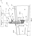
FIG. 2 is a partial schematic sectional illustration of the powerplant at a combustor section of the turbine engine. -
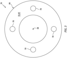
FIG. 3 is a schematic illustration of a plurality of fuel injector assemblies arranged with a combustor. -
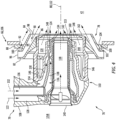
FIG. 4 is a partial sectional illustration of one of the fuel injector assemblies mounted with a bulkhead of the combustor. -
FIG. 5 is a flow diagram of a method of operation for a powerplant. -
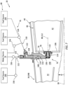
FIGS. 6 and7 are partial schematic sectional illustrations of the powerplant at the combustor section with various fluid systems. -
FIG. 8 is a partial schematic illustration of the powerplant with a power turbine section. -
FIG. 1 illustrates apowerplant 20 powered by agas turbine engine 22. Thepowerplant 20 may be configured as, or otherwise included as part of, an electric power system. This electric power system may be an industrial power system (e.g., a ground-based power system) or an auxiliary power unit (APU) for a mobile unit. Thepowerplant 20 may also or alternatively be configured as, or otherwise included as part of, a propulsion system for the mobile unit. For example, where the mobile unit is an aircraft, thepowerplant 20 may be a turbofan propulsion system, a turbojet propulsion system, a turboprop propulsion system, a turboshaft propulsion system, a propfan propulsion system, a pusher fan propulsion system or any other type of ducted or open rotor propulsion system. Thepowerplant 20 ofFIG. 1 includes amechanical load 24 and acore 26 of theturbine engine 22. - The
mechanical load 24 ofFIG. 1 includes a rotor 28 mechanically driven by theengine core 26. This driven rotor 28 may be a generator rotor 30 in an electric power generator where thepowerplant 20 is (or is part of) the electric power system. Alternatively, the driven rotor 28 may be a bladed propulsor rotor where thepowerplant 20 is (or is part of) the aircraft propulsion system. The driven rotor 28, for example, may be a ducted propulsor rotor or an open (e.g., unducted) propulsor rotor. Examples of the ducted propulsor rotor include, but are not limited to, a fan rotor for the turbofan propulsion system and a (e.g., first stage) compressor rotor for the turbojet propulsion system. Examples of the open propulsor rotor include, but are not limited to, a propfan rotor for the propfan propulsion system, a pusher fan rotor for the pusher fan propulsion system, a propeller rotor for the turboprop propulsion system, and a rotorcraft rotor (e.g., a main helicopter rotor) for the turboshaft propulsion system. However, for ease of description, thepowerplant 20 may be generally described below as the electric power system, and the driven rotor 28 may be generally described below as the generator rotor 30 for the electric power generator. - The
engine core 26 includes acore flowpath 32, acompressor section 34, acombustor section 35 and aturbine section 36. Thecompressor section 34 ofFIG. 1 includes a low pressure compressor (LPC)section 34A and a high pressure compressor (HPC)section 34B. Theturbine section 36 ofFIG. 1 includes a high pressure turbine (HPT)section 36A and a low pressure turbine (LPT)section 36B. Theseengine sections 34A-36B may be arranged sequentially along anaxial centerline 38 of theturbine engine 22 and itsengine core 26 within anengine housing 40. The present invention, however, is not limited to such an axial arrangement. For example, thecombustor section 35 may alternatively be radially outboard of and at least axially overlap theturbine section 36 in other embodiments. - The
core flowpath 32 extends sequentially through theLPC section 34A, theHPC section 34B, thecombustor section 35 and its (e.g., annular)combustion chamber 42, theHPT section 36A and theLPT section 36B from anairflow inlet 44 into thecore flowpath 32 to a combustion products exhaust 46 from thecore flowpath 32. Thecore inlet 44 may be configured as an airflow inlet into theturbine engine 22. Thecore exhaust 46 may be configured as a combustion products exhaust from theturbine engine 22. - The
LPC section 34A includes a bladed low pressure compressor (LPC)rotor 48. TheHPC section 34B includes a bladed high pressure compressor (HPC)rotor 49. TheHPT section 36A includes a bladed high pressure turbine (HPT)rotor 50. TheLPT section 36B includes a bladed low pressure turbine (LPT)rotor 51. Each of these engine rotors 48-51 includes at least one rotor base (e.g., a disk or a hub) and at least one array (e.g., stage) of rotor blades arranged circumferentially around and connected to the respective rotor base. The rotor blades, for example, may be formed integral with or mechanically fastened, welded, brazed and/or otherwise attached to the respective rotor base. - The
LPC rotor 48 is connected to theLPT rotor 51 through alow speed shaft 54. At least (or only) theLPC rotor 48, theLPT rotor 51 and thelow speed shaft 54 collectively form a lowspeed rotating structure 56. TheHPC rotor 49 is connected to theHPT rotor 50 through ahigh speed shaft 58. At least (or only) theHPC rotor 49, theHPT rotor 50 and thehigh speed shaft 58 collectively form a highspeed rotating structure 60. Each of theengine rotating structures 56, 60 (e.g., spools) is rotatably supported by a plurality of bearings connected to theengine housing 40. Each of theengine rotating structures axial centerline 38. - The low
speed rotating structure 56 ofFIG. 1 is connected to the generator rotor 30 (the driven rotor 28) through adrivetrain 62. Thisdrivetrain 62 may be a direct drive drivetrain where, for example, thedrivetrain 62 includes a driveshaft which extends between and couples the lowspeed rotating structure 56 to the generator rotor 30. With such an arrangement, the lowspeed rotating structure 56 and the generator rotor 30 may rotate at a common (the same) rotational velocity. Alternatively, thedrivetrain 62 may be a geared drivetrain where, for example, thedrivetrain 62 includes a geartrain 64 (e.g., an epicyclic gear system, a transmission, etc.) between and coupling the lowspeed rotating structure 56 to the generator rotor 30. With such an arrangement, the lowspeed rotating structure 56 may rotate at a different rotational velocity than the generator rotor 30. While thedrivetrain 62 is shown inFIG. 1 as axially between theturbine section 36 and the generator rotor 30 (the driven rotor 28), it is contemplated thedrivetrain 62 may alternatively be axially between thecompressor section 34 and the generator rotor 30 (the driven rotor 28) in other embodiments. - During powerplant operation, air is directed into the
core flowpath 32 through thecore inlet 44. This air entering thecore flowpath 32 may be referred to as "core air". The core air is compressed by theLPC rotor 48 and theHPC rotor 49 and directed into thecombustion chamber 42 within a (e.g., annular)combustor 66 of thecombustor section 35. Fuel is injected into thecombustion chamber 42 and mixed with the compressed core air to provide a fuel-air mixture. This fuel-air mixture is ignited and combustion products thereof flow through and sequentially cause theHPT rotor 50 and theLPT rotor 51 to rotate. The rotation of theHPT rotor 50 and theLPT rotor 51 respectively drive rotation of theHPC rotor 49 and theLPC rotor 48 and, thus, compression of the air received from thecore inlet 44. The rotation of theLPT rotor 51 also drives rotation of the generator rotor 30 (the driven rotor 28) through thedrivetrain 62. The rotation of the generator rotor 30 facilitates generation of electricity by the electric power generator. - Referring to
FIG. 2 , thepowerplant 20 includes a fluid system 68 (e.g., a fuel-water delivery system) for delivering the fuel for combustion within thecombustion chamber 42. Thisfluid system 68 includes one or more fuel injector assemblies 70 (see alsoFIG. 3 ), a fuel source 72 (e.g., a fuel reservoir, a fuel pipeline, etc.), a water source 74 (e.g., a water reservoir, a water pipeline, etc.) and afluid delivery system 76 for selectively coupling thefuel source 72 and thewater source 74 to eachfuel injector assembly 70. - Referring to
FIG. 3 , thefuel injector assemblies 70 are arranged circumferentially about theaxial centerline 38 in an array; e.g., a circular array. Referring toFIG. 4 , each of thefuel injector assemblies 70 includes an air swirler structure 78 (e.g., a guide swirler) and afuel injector 79. - The
swirler structure 78 extends axially along a centerline axis 80 of theswirler structure 78 from anupstream end 82 of theswirler structure 78 to adownstream end 84 of theswirler structure 78. Theswirler structure 78 extends radially (relative to the swirler axis 80) from aninner side 86 of theswirler structure 78 to anouter side 88 of theswirler structure 78. Theswirler structure 78 extends circumferentially about (e.g., completely around) the swirler axis 80. Theswirler structure 78, for example, may have a full-hoop (e.g., annular) geometry. Theswirler structure 78 ofFIG. 4 includes aguide swirler passage 90 and aswirler cooling passage 92 / a purge passage. - The
guide swirler passage 90 may be formed by or otherwise include anannular swirler channel 94. Thisswirler channel 94 extends longitudinally through a base of theswirler structure 78 from aninlet 96 into theguide swirler passage 90 to anoutlet 98 from theguide swirler passage 90. The guideswirler passage inlet 96 ofFIG. 4 is disposed at (e.g., on, adjacent or proximate) the structureouter side 88, adjacent or near the structureupstream end 82. The guideswirler passage outlet 98 ofFIG. 4 is disposed at the structuredownstream end 84, adjacent or near the structureinner side 86. With this arrangement, at least a downstream end portion of theguide swirler passage 90 and itsswirler channel 94 radially tapers (e.g., converges) as theguide swirler passage 90 extends longitudinally to its guideswirler passage outlet 98. Theguide swirler passage 90 may also include one or more vanes (e.g., at its inlet 96) configured to swirl air flowing longitudinally within theguide swirler passage 90 circumferentially about the swirler axis 80. - The
cooling passage 92 may be formed by or otherwise include a plurality of coolingapertures 100 / purge apertures arranged circumferentially about the swirler axis 80 in an array; e.g., a circular array. Each of these coolingapertures 100 extends longitudinally through a flange of theswirler structure 78 from aninlet 102 into the cooling passage 92 (e.g., an array of inlet orifices) to anoutlet 104 from the cooling passage 92 (e.g., an array of outlet orifices). Thecooling passage inlet 102 ofFIG. 4 is disposed in an upstream side of the flange. Thecooling passage outlet 104 ofFIG. 4 is disposed in a downstream side of the flange, and radially inboard of thecooling passage inlet 102. With this arrangement, thecooling passage 92 radially tapers (e.g., converges) as thecooling passage 92 extends longitudinally to itscooling passage outlet 104. - The
swirler structure 78 may be (e.g., movably) mounted to abulkhead 106 of thecombustor 66. The flange, for example, may be abutted axially against and coupled to thebulkhead 106. This coupling between theswirler structure 78 and thebulkhead 106 may be a compliant coupling such that, for example, theswirler structure 78 can shift (e.g., slide) radially and/or circumferentially relative to thebulkhead 106 to facilitate differential thermal expansion between the respectivefuel injector assembly 70 and thecombustor 66 and itsbulkhead 106. - The
fuel injector 79 ofFIG. 2 includes afuel injector stem 108 and afuel injector nozzle 110. The injector stem 108 is configured to support and route fluid to theinjector nozzle 110 from an exterior of theengine housing 40. Theinjector nozzle 110 is cantilevered from theinjector stem 108. Theinjector nozzle 110 projects along a centerline axis 112 of theinjector nozzle 110 into a bore of theswirler structure 78, which nozzle axis 112 may be parallel with (e.g., coaxial to) the swirler axis 80. Atip 113 of theinjector nozzle 110 may disposed within the swirler bore, or otherwise at the structuredownstream end 84. Thefuel injector 79 ofFIG. 4 is configured with one or morefluid passages more air passages fuel injector 79 and itsinjector nozzle 110 may be configured to move (e.g., translate) axially along the axis 80, 112 to further facilitate differential thermal expansion between the respectivefuel injector assembly 70 and thecombustor 66 and itsbulkhead 106. - The first fluid passage 114 (e.g., a gaseous fluid passage) extends longitudinally through the
fuel injector 79 from an inlet 122 (see alsoFIG. 2 ) into thefirst fluid passage 114 to anoutlet 124 from thefirst fluid passage 114. The firstfluid passage inlet 122 is disposed at an exterior end 126 (seeFIG. 2 ) of theinjector stem 108. The firstfluid passage outlet 124 is disposed at thenozzle tip 113. Thefirst fluid passage 114 ofFIG. 4 includes afirst passage conduit 128 in theinjector stem 108 and an annularfirst passage channel 130 in theinjector nozzle 110. Thefirst passage conduit 128 fluidly couples the firstfluid passage inlet 122 to thefirst passage channel 130. Thefirst passage conduit 128 ofFIG. 4 , for example, extends longitudinally within thefuel injector 79 and its injector stem 108 from the firstfluid passage inlet 122 to thefirst passage channel 130. Thefirst passage channel 130 fluidly couples thefirst passage conduit 128 to the firstfluid passage outlet 124. Thefirst passage channel 130 ofFIG. 4 , for example, extends longitudinally within thefuel injector 79 and itsinjector nozzle 110 from thefirst passage conduit 128 to the firstfluid passage outlet 124. Thisfirst passage channel 130 extends circumferentially around and may be coaxial with the nozzle axis 112. - The second fluid passage 116 (e.g., a liquid fluid passage) extends longitudinally through the
fuel injector 79 from an inlet 132 (see alsoFIG. 2 ) into thesecond fluid passage 116 to anoutlet 134 from thesecond fluid passage 116. The secondfluid passage inlet 132 is disposed at the exterior end 126 (seeFIG. 2 ) of theinjector stem 108. The secondfluid passage outlet 134 is disposed at thenozzle tip 113. Thesecond fluid passage 116 ofFIG. 4 includes asecond passage conduit 136 in theinjector stem 108 and an annularsecond passage channel 138 in theinjector nozzle 110. Thesecond passage conduit 136 fluidly couples the secondfluid passage inlet 132 to thesecond passage channel 138. Thesecond passage conduit 136 ofFIG. 4 , for example, extends longitudinally within thefuel injector 79 and its injector stem 108 from the secondfluid passage inlet 132 to thesecond passage channel 138. Thesecond passage channel 138 fluidly couples thesecond passage conduit 136 to the secondfluid passage outlet 134. Thesecond passage channel 138 ofFIG. 4 , for example, extends longitudinally within thefuel injector 79 and itsinjector nozzle 110 from thesecond passage conduit 136 to the secondfluid passage outlet 134. Thissecond passage channel 138 extends circumferentially around and may be coaxial with the nozzle axis 112. Here, thesecond passage channel 138 and the secondfluid passage outlet 134 are respectively radially inboard of thefirst passage channel 130 and the firstfluid passage outlet 124. The firstfluid passage outlet 124 may also be (e.g., slightly) axially recessed upstream from the secondfluid passage outlet 134. At least a downstream end portion of thesecond fluid passage 116 and itssecond passage channel 138 radially tapers (e.g., converges) as thesecond fluid passage 116 extends longitudinally to its secondfluid passage outlet 134. - The
inner air passage 118 may be formed by or otherwise include a central bore through theinjector nozzle 110. Theinner air passage 118 extends longitudinally through theinjector nozzle 110 from aninlet 140 into theinner air passage 118 to anoutlet 142 from theinner air passage 118. The innerair passage inlet 140 is disposed at an upstream end of theinjector nozzle 110. The innerair passage outlet 142 is disposed at thenozzle tip 113, whichnozzle tip 113 ofFIG. 4 is axially opposite the nozzle upstream end. Here, theinner air passage 118 is radially inboard of each of thefluid passages injector nozzle 110. Thefirst passage channel 130 and thesecond passage channel 138 ofFIG. 4 , for example, each circumscribe theinner air passage 118. Theinner air passage 118 may also include an air swirler configured to swirl (e.g., at its inlet 140) air flowing longitudinally within theinner air passage 118 circumferentially about the nozzle axis 112. - The
outer air passage 120 may be formed by or otherwise include an annularair passage channel 144. Theouter air passage 120 extends longitudinally through theinjector nozzle 110 from aninlet 146 into theouter air passage 120 to anoutlet 148 from theouter air passage 120. The outerair passage inlet 146 is disposed at an outer side of theinjector nozzle 110. The outerair passage outlet 148 is disposed at thenozzle tip 113. Here, theouter air passage 120 is radially outboard of the each of theinjector passages outer air passage 120 may thereby circumscribe each of theinjector passages outer air passage 120 and itsair passage channel 144 radially tapers (e.g., converges) as theouter air passage 120 extends longitudinally to its outerair passage outlet 148. Theouter air passage 120 may also include one or more vanes and/or circumferentially canted inlet orifices (e.g., at its inlet 146) configured to swirl air flowing longitudinally within theouter air passage 120 circumferentially about the swirler axis 80. - Referring to
FIG. 2 , thefluid delivery system 76 includes afirst passage circuit 150 and asecond passage circuit 152. Thefirst passage circuit 150 fluidly couples thefuel source 72 and thewater source 74 to thefirst fluid passage 114 and its firstfluid passage inlet 122. Thisfirst passage circuit 150 may include one or more first flow regulators 154 (e.g., valves, pumps, etc.) configured to control fluid flow (e.g., meter fluid) from eachfluid source first fluid passage 114. Thesecond passage circuit 152 fluidly couples thewater source 74 to thesecond fluid passage 116 and its secondfluid passage inlet 132. Thissecond passage circuit 152 may include at least one second flow regulator 156 (e.g., valve, pump, etc.) configured to control fluid flow (e.g., meter fluid) from thewater source 74 to thesecond fluid passage 116. -
FIG. 5 is a flow diagram of amethod 500 of operation for a powerplant. For ease of description, theoperating method 500 is described below with reference to thepowerplant 20 ofFIG. 1 and itsfluid system 68 ofFIGS. 2-4 . Theoperating method 500 of the present invention, however, is not limited to such an exemplary arrangements as discussed below in further detail. - In
step 502, thefirst passage circuit 150 delivers a fuel-water mixture to eachfuel injector 79 and itsfirst fluid passage 114. Thefirst passage circuit 150, for example, may mix gaseous fuel received from thefuel source 72 with liquid water (e.g., a mist of liquid water) received from thewater source 74 within a volume outside of therespective fuel injector 79. This fuel-water mixture may then be directed into thefirst fluid passage 114 through itsrespective inlet 122. - In
step 504, the fuel-water mixture is injected into thecombustion chamber 42. The fuel-water mixture, for example, is directed through thefirst fluid passage 114 to itsrespective outlet 124. This fuel-water mixture may then be directed out of theinjector nozzle 110 through the firstfluid passage outlet 124 and into thecombustion chamber 42 as an annular flow of the fuel-water mixture. The fuel-water mixture directed out of the firstfluid passage outlet 124 may still be composed of the liquid water and the gaseous fuel. Here, the gaseous fuel may be a non-hydrocarbon fuel such as hydrogen fuel; e.g., hydrogen (H2) gas. - In
step 506, thesecond passage circuit 152 delivers additional liquid water to eachfuel injector 79 and itssecond fluid passage 116. Thesecond passage circuit 152, for example, directs the additional liquid water from thewater source 74 into thesecond fluid passage 116 through itsrespective inlet 132. - In
step 508, the additional liquid water is injected into thecombustion chamber 42. The additional liquid water, for example, is directed through thesecond fluid passage 116 to itsrespective outlet 134. This additional liquid water may then be directed out of theinjector nozzle 110 through the secondfluid passage outlet 134 and into thecombustion chamber 42 as an annular flow of the additional liquid water. Here, the flow of the additional liquid water is radially inboard of and circumscribed by the flow of the fuel-water mixture. - In
step 510, eachfuel injector assembly 70 directs compressed air into thecombustion chamber 42. Eachpassage plenum 158 surrounding and/or otherwise adjacent thecombustor 66 into thecombustion chamber 42 as a respective flow of compressed air. Here, the flows of the compressed air output from thepassages - In
step 512, the gaseous fuel and the compressed air mix within thecombustion chamber 42 to provide the fuel air mixture. Instep 514, the fuel-air mixture is ignited to generate combustion products and power operation of thepowerplant 20 and itsturbine engine 22 as described above. - A non-hydrocarbon fuel such as the hydrogen gas may have a relatively quick flame speed. The
injector nozzle 110 and itsnozzle tip 113 therefore may be subject to relatively high temperatures, particular at its face surfaces 160 and 162 (seeFIG. 4 ). The temperatures of the face surfaces 160 and 162, however, may be reduced by injecting the liquid water into thecombustion chamber 42. The water may provide a fluid barrier along theface surface nozzle tip 113. The inclusion of the liquid water in the fuel-water mixture, in particular, may reduce the temperature of theouter face surface 162 at thenozzle tip 113. This may facilitate fueling theturbine engine 22 combustion process, for example, completely (e.g., only) with the hydrogen fuel. - Each
fuel injector 79 may inject a first quantity (A) of water into thecombustion chamber 42 via the fuel-water mixture flow; e.g., through thefirst fluid passage 114 and itsoutlet 124. Eachfuel injector 79 may inject a second quantity of water (B) into thecombustion chamber 42 via the additional liquid water flow; e.g., through thesecond fluid passage 116 and itsoutlet 134. A ratio of the first quantity of water to the second quantity of water (A/B) may be less than one (1); e.g., A/B < 1. The first quantity of water, for example, may account for between thirty percent (30%) and seventy percent (70%) of the water injected into thecombustion chamber 42 by therespective fuel injector 79. For example, where higher combustion temperatures are expected (e.g., fueling with only hydrogen gas), the first quantity of water may account for between forty percent (40%) and sixty percent (60%) of the water injected into thecombustion chamber 42 by therespective fuel injector 79. In another example, where lower combustion temperatures are expected (e.g., fueling with a mixture of gases as discussed below), the first quantity of water may account for between thirty percent (30%) and forty percent (40%) of the water injected into thecombustion chamber 42 by therespective fuel injector 79. The present invention, however, is not limited to the foregoing exemplary relationships as cooling parameters may change based on nozzle design. - Referring to
FIG. 6 , thefluid system 68 may include a second fuel source 164 (e.g., a fuel reservoir, a fuel pipeline, etc.). For example, where thefirst fuel source 72 provides the non-hydrocarbon fuel such as the hydrogen gas, thesecond fuel source 164 may provide a hydrocarbon fuel such as gaseous methane (e.g., natural gas). In one mode of operation, thefirst passage circuit 150 ofFIG. 6 may be operated to (e.g., only) mix the hydrogen gas with the liquid water to provide the fuel-water mixture as described above. In another mode of operation, thefirst passage circuit 150 may be operated to mix both the hydrogen gas and the methane gas with the liquid water to provide the fuel-water mixture. In another mode of operation, thefirst passage circuit 150 may be operated to (e.g., only) mix the hydrogen gas with the methane gas (without the liquid water) to provide a fuel mixture to thefirst fluid passage 114 rather than the fuel-water mixture. In still another mode of operation, thefirst passage circuit 150 may be operated to (e.g., only) provide the methane gas to thefirst fluid passage 114 rather than the fuel-water mixture. In this mode, no water is mixed with the methane gas directed through thefirst fluid passage 114. During each of these modes, thesecond passage circuit 152 may continue to provide the additional liquid water to thesecond fluid passage 116 as described above. - Where the
first passage circuit 150 provides a mixture of the hydrogen gas and the methane gas, the mixture of the hydrogen gas and the methane gas may be selectively tailored. Thefirst passage circuit 150, for example, may mix a first quantity (X) of the hydrogen gas with a second quantity (Y) of the methane gas. A ratio of the first quantity of the hydrogen gas to the second quantity of the methane gas (e.g., X/Y) may be less or equal to than one (1); e.g., X/Y ≤ 1. However, it is contemplated the ratio of the first quantity of the hydrogen gas to the second quantity of the methane gas (e.g., X/Y) may alternatively be greater than one (1) (e.g., X/Y > 1) to reduce, for example, emission of pollutants generated by combustion of a hydrocarbon fuel. In general, as the ratio of X/Y increases, the quantity of the liquid water mixed with the gaseous fuel within thefirst passage circuit 150 also increases to compensate for the higher hydrogen fuel content, which may promote fastener flame speed and/or high combustion temperature. In some embodiments, where the hydrogen gas accounts for thirty percent (30%) or more of the mixture of the hydrogen gas and the methane gas (up to 100% hydrogen gas, 0% methane gas), at least thirty percent (30%) of the water introduced into thecombustion chamber 42 by therespective fuel injector 79 may flow through thefirst fluid passage 114 with the gaseous fuel. The balance of the water may flow through thesecond fluid passage 116. - While the examples provided above include hydrogen gas and/or methane gas, the present invention is not limited to such exemplary gas fuels. For example, it is contemplated other non-hydrocarbon fuels such as, but not limited to, gaseous ammonia (NH3 gas) may be provided by the
first fuel source 72. In addition or alternatively, it is contemplated other hydrocarbon fuels such as, but not limited to, propane gas may be provided by thesecond fuel source 164. - Referring to
FIG. 7 , thefluid system 68 may also or alternatively include another fuel source (e.g., a fuel reservoir, a fuel pipeline, etc.) - athird fuel source 166 inFIG. 7 . Thisthird fuel source 166 may provide a liquid fuel; e.g., a liquid hydrocarbon fuel such as liquid Jet A fuel or liquid No. 2 fuel oil. Thisthird fuel source 166 may be provided as a backup fuel source for use in, for example, a backup mode of operation. For example, when selected, thesecond passage circuit 152 may mix the liquid water and the liquid fuel to provide a liquid fuel-water mixture. This liquid fuel-water mixture may then be directed into thesecond fluid passage 116 for injection into thecombustion chamber 42 and combustion of the liquid fuel. However, during such a mode of operation, thefirst passage circuit 150 may close; e.g., fluidly decouple each fluid source (e.g., 72, 74, 164) from thefirst fluid passage 114. Thus, during this mode of operation, no fluid may flow through thefirst fluid passage 114. - Another example of fuel injector assemblies which may be used with the
operating method 500 of the present invention is disclosed inU.S. Patent No. 10,228,137 - The
engine core 26 is shown inFIG. 1 with tworotating assemblies engine core 26 may alternatively be configured with a single rotating assembly, or with three or more rotating assemblies. Theengine core 26 ofFIG. 8 , for example, is configured with an additional turbine rotor 168 (e.g., a power turbine (PT) rotor) coupled to and configured to drive rotation of the driven rotor 28; e.g., power themechanical load 24. Here, theturbine rotor 168 is disposed within apower turbine section 36C of theturbine section 36, whichpower turbine section 36C is downstream of theturbine section 36B (here, an intermediate turbine section) along thecore flowpath 32. - While various embodiments of the present invention have been described, it will be apparent to those of ordinary skill in the art that many more embodiments and implementations are possible within the scope of the invention. For example, the present invention as described herein includes several aspects and embodiments that include particular features. Although these features may be described individually, it is within the scope of the present invention that some or all of these features may be combined with any one of the aspects and remain within the scope of the invention. Accordingly, the present invention is not to be restricted except in light of the attached claims and their equivalents.
Claims (15)
- A method of operation comprising:directing a fuel-water mixture within a first passage (114) of a fuel injector (79) to a first passage outlet (124) of the fuel injector (79), the fuel-water mixture including liquid water and gaseous fuel;injecting the fuel-water mixture into a combustion chamber (42) through the first passage outlet (124), the combustion chamber (42) being within a combustor (66) of a turbine engine (22); andigniting a fuel-air mixture within the combustion chamber (42), the fuel-air mixture comprising the gaseous fuel.
- The method of claim 1, wherein the gaseous fuel comprises a gaseous non-hydrocarbon fuel.
- The method of claim 1 or 2, wherein the gaseous fuel comprises a gaseous hydrocarbon fuel.
- The method of any preceding claim, wherein the gaseous fuel comprises hydrogen gas.
- The method of claim 4, wherein the gaseous fuel further comprises methane gas.
- The method of claim 5, wherein a ratio of a quantity of the hydrogen gas to a quantity of the methane gas within the gaseous fuel is equal to or less than one.
- The method of claim 5, wherein a ratio of a quantity of the hydrogen gas to a quantity of the methane gas within the gaseous fuel is greater than one.
- The method of claim 1, wherein the gaseous fuel comprises hydrogen gas and the fuel-water mixture consists of the liquid water and the hydrogen gas.
- The method of any preceding claim, further comprising:mixing the liquid water with the gaseous fuel outside of the fuel injector (79) to provide the fuel-water mixture; anddirecting the fuel-water mixture into the fuel injector (79) through a first passage inlet (122) of the fuel injector (79).
- The method of any preceding claim, further comprising:directing additional liquid water within a second passage (116) of the fuel injector (79) to a second passage outlet (134) of the fuel injector (79), the second passage (116) fluidly discrete from the first passage (114); andinjecting the additional liquid water into the combustion chamber (42) through the second passage outlet (134).
- The method of claim 10, wherein a ratio of a quantity of the liquid water within the fuel-water mixture to a quantity of the additional liquid water is less than one.
- The method of claim 10 or 11, wherein the liquid water within the fuel-water mixture accounts for between thirty percent and seventy percent of water introduced into the combustion chamber (42) through the fuel injector (79).
- The method of any of claims 10 to 12, wherein:the additional water is injected into the combustion chamber (42) as a flow of the additional liquid water; andthe fuel-water mixture is injected into the combustion chamber (42) as a flow of the fuel-water mixture; andthe flow of the fuel-water mixture circumscribes the flow of the additional liquid water.
- The method of any preceding claim, further comprising:
directing a flow of compressed air out of the fuel injector (79) as a flow of compressed air, wherein the fuel-water mixture is injected into the combustion chamber as a flow of the fuel-water mixture, and wherein the flow of the fuel-water mixture circumscribes the flow of compressed air. - The method of any of claims 1 to 13, further comprising:
directing a flow of compressed air out of the fuel injector (79) as a flow of compressed air, wherein the fuel-water mixture is injected into the combustion chamber (42) as a flow of the fuel-water mixture, and wherein the flow of compressed air circumscribes the flow of the fuel-water mixture.
Applications Claiming Priority (1)
| Application Number | Priority Date | Filing Date | Title |
|---|---|---|---|
| US18/211,067 US20240418127A1 (en) | 2023-06-16 | 2023-06-16 | Gaseous fuel and liquid water injection for turbine engine |
Publications (1)
| Publication Number | Publication Date |
|---|---|
| EP4477949A1 true EP4477949A1 (en) | 2024-12-18 |
Family
ID=90735170
Family Applications (1)
| Application Number | Title | Priority Date | Filing Date |
|---|---|---|---|
| EP24170650.6A Pending EP4477949A1 (en) | 2023-06-16 | 2024-04-16 | Gaseous fuel and liquid water injection for turbine engine |
Country Status (2)
| Country | Link |
|---|---|
| US (1) | US20240418127A1 (en) |
| EP (1) | EP4477949A1 (en) |
Cited By (1)
| Publication number | Priority date | Publication date | Assignee | Title |
|---|---|---|---|---|
| EP4517066A1 (en) * | 2023-08-28 | 2025-03-05 | Pratt & Whitney Canada Corp. | Multi-fuel gas turbine engine with water injection |
Citations (5)
| Publication number | Priority date | Publication date | Assignee | Title |
|---|---|---|---|---|
| WO1993022601A1 (en) * | 1992-04-23 | 1993-11-11 | Solar Turbines Incorporated | Premix liquid and gaseous combustion nozzle for use with a gas turbine engine |
| US9523311B2 (en) * | 2007-05-08 | 2016-12-20 | General Electric Technology Gmbh | Method of operating a gas turbine, and gas turbine with water injection |
| US9958152B2 (en) * | 2014-08-14 | 2018-05-01 | Siemens Aktiengesellschaft | Multi-functional fuel nozzle with an atomizer array |
| US10041417B2 (en) * | 2011-11-02 | 2018-08-07 | Kawasaki Jukogyo Kabushiki Kaisha | Gas turbine system with injection water pressurization passage |
| US10228137B2 (en) | 2013-08-30 | 2019-03-12 | United Technologies Corporation | Dual fuel nozzle with swirling axial gas injection for a gas turbine engine |
Family Cites Families (18)
| Publication number | Priority date | Publication date | Assignee | Title |
|---|---|---|---|---|
| US5259184A (en) * | 1992-03-30 | 1993-11-09 | General Electric Company | Dry low NOx single stage dual mode combustor construction for a gas turbine |
| US5404711A (en) * | 1993-06-10 | 1995-04-11 | Solar Turbines Incorporated | Dual fuel injector nozzle for use with a gas turbine engine |
| US5426933A (en) * | 1994-01-11 | 1995-06-27 | Solar Turbines Incorporated | Dual feed injection nozzle with water injection |
| US5669218A (en) * | 1995-05-31 | 1997-09-23 | Dresser-Rand Company | Premix fuel nozzle |
| US7162864B1 (en) * | 2003-11-04 | 2007-01-16 | Sandia National Laboratories | Method for control of NOx emission from combustors using fuel dilution |
| US7082765B2 (en) * | 2004-09-01 | 2006-08-01 | General Electric Company | Methods and apparatus for reducing gas turbine engine emissions |
| JP5473934B2 (en) * | 2007-11-27 | 2014-04-16 | アルストム テクノロジー リミテッド | Apparatus and method for operating gas turbine equipment using second hydrogen-rich fuel |
| US20110314833A1 (en) * | 2010-06-29 | 2011-12-29 | Symonds Richard A | Additive injection system for use with a turbine engine and methods of assembling same |
| US9243804B2 (en) * | 2011-10-24 | 2016-01-26 | General Electric Company | System for turbine combustor fuel mixing |
| EP2933561A4 (en) * | 2012-12-13 | 2016-08-24 | Kawasaki Heavy Ind Ltd | GAS TURBINE COMBUSTION CHAMBER ACCEPTING MULTIPLE FUEL |
| JP6395363B2 (en) * | 2013-10-11 | 2018-09-26 | 川崎重工業株式会社 | Gas turbine fuel injection device |
| JP6410924B2 (en) * | 2014-08-14 | 2018-10-24 | シーメンス アクチエンゲゼルシヤフトSiemens Aktiengesellschaft | Multifunctional fuel nozzle with dual orifice atomizer |
| US9964043B2 (en) * | 2014-11-11 | 2018-05-08 | General Electric Company | Premixing nozzle with integral liquid evaporator |
| US20170082024A1 (en) * | 2015-09-17 | 2017-03-23 | Siemens Energy, Inc. | Independently controlled three stage water injection in a diffusion burner |
| JP6722491B2 (en) * | 2016-04-01 | 2020-07-15 | 川崎重工業株式会社 | Gas turbine combustor |
| WO2020242556A1 (en) * | 2019-05-30 | 2020-12-03 | Siemens Aktiengesellschaft | Gas turbine water injection for emissions reduction |
| US12429223B2 (en) * | 2022-03-17 | 2025-09-30 | Ge Vernova Infrastructure Technology Llc | Fuel supply system for a combustor |
| GB2602936B (en) * | 2022-04-20 | 2023-02-15 | Derwent Tech Ltd | Propulsion system |
-
2023
- 2023-06-16 US US18/211,067 patent/US20240418127A1/en active Pending
-
2024
- 2024-04-16 EP EP24170650.6A patent/EP4477949A1/en active Pending
Patent Citations (5)
| Publication number | Priority date | Publication date | Assignee | Title |
|---|---|---|---|---|
| WO1993022601A1 (en) * | 1992-04-23 | 1993-11-11 | Solar Turbines Incorporated | Premix liquid and gaseous combustion nozzle for use with a gas turbine engine |
| US9523311B2 (en) * | 2007-05-08 | 2016-12-20 | General Electric Technology Gmbh | Method of operating a gas turbine, and gas turbine with water injection |
| US10041417B2 (en) * | 2011-11-02 | 2018-08-07 | Kawasaki Jukogyo Kabushiki Kaisha | Gas turbine system with injection water pressurization passage |
| US10228137B2 (en) | 2013-08-30 | 2019-03-12 | United Technologies Corporation | Dual fuel nozzle with swirling axial gas injection for a gas turbine engine |
| US9958152B2 (en) * | 2014-08-14 | 2018-05-01 | Siemens Aktiengesellschaft | Multi-functional fuel nozzle with an atomizer array |
Cited By (1)
| Publication number | Priority date | Publication date | Assignee | Title |
|---|---|---|---|---|
| EP4517066A1 (en) * | 2023-08-28 | 2025-03-05 | Pratt & Whitney Canada Corp. | Multi-fuel gas turbine engine with water injection |
Also Published As
| Publication number | Publication date |
|---|---|
| US20240418127A1 (en) | 2024-12-19 |
Similar Documents
| Publication | Publication Date | Title |
|---|---|---|
| US12215870B2 (en) | Method of operating a gas turbine combustor comprising injecting a diluent into the primary and secondary combustion zones | |
| US12169069B2 (en) | System for producing diluent for a gas turbine engine | |
| EP4431813A1 (en) | Fuel injector assembly for gas turbine engine | |
| US20230399980A1 (en) | Multi-temperature fuel injectors for a gas turbine engine | |
| EP4421388A1 (en) | Fuel injector assembly for gas turbine engine | |
| US12486982B2 (en) | Combustor having a main chamber and one or more trapped vortex cavities | |
| EP4431716A1 (en) | Introducing steam into core air upstream of turbine engine diffuser plenum | |
| US20240209801A1 (en) | Gas turbine operation | |
| US20240209791A1 (en) | Staged combustor | |
| US20240418127A1 (en) | Gaseous fuel and liquid water injection for turbine engine | |
| EP4431809B1 (en) | Modulating fluid flow within a turbine engine using steam | |
| US12305571B2 (en) | Combustor | |
| EP4368889A2 (en) | Fuel injector assembly for gas turbine engine | |
| US12392287B2 (en) | Steam cooling turbine stator vane array | |
| US11905837B2 (en) | Sealing system including a seal assembly between components | |
| US12535215B2 (en) | Combustor including a steam injector operably injecting steam into a trapped vortex cavity | |
| US12416258B2 (en) | Asymmetric introduction of steam into turbine engine combustion chamber | |
| EP4431718A1 (en) | Selective steam distribution to steam cooled zones in a turbine engine | |
| US20260085634A1 (en) | Gas turbine engine system with fuel driven turbine | |
| US20250075656A1 (en) | Multi-fuel gas turbine engine with water injection |
Legal Events
| Date | Code | Title | Description |
|---|---|---|---|
| PUAI | Public reference made under article 153(3) epc to a published international application that has entered the european phase |
Free format text: ORIGINAL CODE: 0009012 |
|
| STAA | Information on the status of an ep patent application or granted ep patent |
Free format text: STATUS: THE APPLICATION HAS BEEN PUBLISHED |
|
| AK | Designated contracting states |
Kind code of ref document: A1 Designated state(s): AL AT BE BG CH CY CZ DE DK EE ES FI FR GB GR HR HU IE IS IT LI LT LU LV MC ME MK MT NL NO PL PT RO RS SE SI SK SM TR |
|
| STAA | Information on the status of an ep patent application or granted ep patent |
Free format text: STATUS: REQUEST FOR EXAMINATION WAS MADE |
|
| 17P | Request for examination filed |
Effective date: 20250618 |
|
| STAA | Information on the status of an ep patent application or granted ep patent |
Free format text: STATUS: EXAMINATION IS IN PROGRESS |
|
| 17Q | First examination report despatched |
Effective date: 20250807 |
|
| GRAP | Despatch of communication of intention to grant a patent |
Free format text: ORIGINAL CODE: EPIDOSNIGR1 |
|
| STAA | Information on the status of an ep patent application or granted ep patent |
Free format text: STATUS: GRANT OF PATENT IS INTENDED |
|
| INTG | Intention to grant announced |
Effective date: 20260115 |
|
| GRAS | Grant fee paid |
Free format text: ORIGINAL CODE: EPIDOSNIGR3 |
|
| GRAA | (expected) grant |
Free format text: ORIGINAL CODE: 0009210 |
|
| STAA | Information on the status of an ep patent application or granted ep patent |
Free format text: STATUS: THE PATENT HAS BEEN GRANTED |