EP4477904A1 - Grease-filled ball bearing - Google Patents
Grease-filled ball bearing Download PDFInfo
- Publication number
- EP4477904A1 EP4477904A1 EP23752850.0A EP23752850A EP4477904A1 EP 4477904 A1 EP4477904 A1 EP 4477904A1 EP 23752850 A EP23752850 A EP 23752850A EP 4477904 A1 EP4477904 A1 EP 4477904A1
- Authority
- EP
- European Patent Office
- Prior art keywords
- grease
- cage
- claw
- radially inner
- annular portion
- Prior art date
- Legal status (The legal status is an assumption and is not a legal conclusion. Google has not performed a legal analysis and makes no representation as to the accuracy of the status listed.)
- Pending
Links
Images






Classifications
-
- F—MECHANICAL ENGINEERING; LIGHTING; HEATING; WEAPONS; BLASTING
- F16—ENGINEERING ELEMENTS AND UNITS; GENERAL MEASURES FOR PRODUCING AND MAINTAINING EFFECTIVE FUNCTIONING OF MACHINES OR INSTALLATIONS; THERMAL INSULATION IN GENERAL
- F16C—SHAFTS; FLEXIBLE SHAFTS; ELEMENTS OR CRANKSHAFT MECHANISMS; ROTARY BODIES OTHER THAN GEARING ELEMENTS; BEARINGS
- F16C33/00—Parts of bearings; Special methods for making bearings or parts thereof
- F16C33/30—Parts of ball or roller bearings
- F16C33/66—Special parts or details in view of lubrication
- F16C33/6603—Special parts or details in view of lubrication with grease as lubricant
- F16C33/6629—Details of distribution or circulation inside the bearing, e.g. grooves on the cage or passages in the rolling elements
-
- F—MECHANICAL ENGINEERING; LIGHTING; HEATING; WEAPONS; BLASTING
- F16—ENGINEERING ELEMENTS AND UNITS; GENERAL MEASURES FOR PRODUCING AND MAINTAINING EFFECTIVE FUNCTIONING OF MACHINES OR INSTALLATIONS; THERMAL INSULATION IN GENERAL
- F16C—SHAFTS; FLEXIBLE SHAFTS; ELEMENTS OR CRANKSHAFT MECHANISMS; ROTARY BODIES OTHER THAN GEARING ELEMENTS; BEARINGS
- F16C33/00—Parts of bearings; Special methods for making bearings or parts thereof
- F16C33/30—Parts of ball or roller bearings
- F16C33/38—Ball cages
- F16C33/41—Ball cages comb-shaped
- F16C33/412—Massive or moulded comb cages, e.g. snap ball cages
- F16C33/414—Massive or moulded comb cages, e.g. snap ball cages formed as one-piece cages, i.e. monoblock comb cages
- F16C33/416—Massive or moulded comb cages, e.g. snap ball cages formed as one-piece cages, i.e. monoblock comb cages made from plastic, e.g. injection moulded comb cages
-
- F—MECHANICAL ENGINEERING; LIGHTING; HEATING; WEAPONS; BLASTING
- F16—ENGINEERING ELEMENTS AND UNITS; GENERAL MEASURES FOR PRODUCING AND MAINTAINING EFFECTIVE FUNCTIONING OF MACHINES OR INSTALLATIONS; THERMAL INSULATION IN GENERAL
- F16C—SHAFTS; FLEXIBLE SHAFTS; ELEMENTS OR CRANKSHAFT MECHANISMS; ROTARY BODIES OTHER THAN GEARING ELEMENTS; BEARINGS
- F16C33/00—Parts of bearings; Special methods for making bearings or parts thereof
- F16C33/30—Parts of ball or roller bearings
- F16C33/38—Ball cages
- F16C33/41—Ball cages comb-shaped
- F16C33/418—Details of individual pockets, e.g. shape or ball retaining means
-
- F—MECHANICAL ENGINEERING; LIGHTING; HEATING; WEAPONS; BLASTING
- F16—ENGINEERING ELEMENTS AND UNITS; GENERAL MEASURES FOR PRODUCING AND MAINTAINING EFFECTIVE FUNCTIONING OF MACHINES OR INSTALLATIONS; THERMAL INSULATION IN GENERAL
- F16C—SHAFTS; FLEXIBLE SHAFTS; ELEMENTS OR CRANKSHAFT MECHANISMS; ROTARY BODIES OTHER THAN GEARING ELEMENTS; BEARINGS
- F16C33/00—Parts of bearings; Special methods for making bearings or parts thereof
- F16C33/30—Parts of ball or roller bearings
- F16C33/66—Special parts or details in view of lubrication
- F16C33/6603—Special parts or details in view of lubrication with grease as lubricant
- F16C33/6607—Retaining the grease in or near the bearing
- F16C33/6614—Retaining the grease in or near the bearing in recesses or cavities provided in retainers, races or rolling elements
-
- F—MECHANICAL ENGINEERING; LIGHTING; HEATING; WEAPONS; BLASTING
- F16—ENGINEERING ELEMENTS AND UNITS; GENERAL MEASURES FOR PRODUCING AND MAINTAINING EFFECTIVE FUNCTIONING OF MACHINES OR INSTALLATIONS; THERMAL INSULATION IN GENERAL
- F16C—SHAFTS; FLEXIBLE SHAFTS; ELEMENTS OR CRANKSHAFT MECHANISMS; ROTARY BODIES OTHER THAN GEARING ELEMENTS; BEARINGS
- F16C19/00—Bearings with rolling contact, for exclusively rotary movement
- F16C19/02—Bearings with rolling contact, for exclusively rotary movement with bearing balls essentially of the same size in one or more circular rows
- F16C19/04—Bearings with rolling contact, for exclusively rotary movement with bearing balls essentially of the same size in one or more circular rows for radial load mainly
- F16C19/06—Bearings with rolling contact, for exclusively rotary movement with bearing balls essentially of the same size in one or more circular rows for radial load mainly with a single row or balls
-
- F—MECHANICAL ENGINEERING; LIGHTING; HEATING; WEAPONS; BLASTING
- F16—ENGINEERING ELEMENTS AND UNITS; GENERAL MEASURES FOR PRODUCING AND MAINTAINING EFFECTIVE FUNCTIONING OF MACHINES OR INSTALLATIONS; THERMAL INSULATION IN GENERAL
- F16C—SHAFTS; FLEXIBLE SHAFTS; ELEMENTS OR CRANKSHAFT MECHANISMS; ROTARY BODIES OTHER THAN GEARING ELEMENTS; BEARINGS
- F16C2240/00—Specified values or numerical ranges of parameters; Relations between them
- F16C2240/26—Speed, e.g. rotational speed
-
- F—MECHANICAL ENGINEERING; LIGHTING; HEATING; WEAPONS; BLASTING
- F16—ENGINEERING ELEMENTS AND UNITS; GENERAL MEASURES FOR PRODUCING AND MAINTAINING EFFECTIVE FUNCTIONING OF MACHINES OR INSTALLATIONS; THERMAL INSULATION IN GENERAL
- F16C—SHAFTS; FLEXIBLE SHAFTS; ELEMENTS OR CRANKSHAFT MECHANISMS; ROTARY BODIES OTHER THAN GEARING ELEMENTS; BEARINGS
- F16C2300/00—Application independent of particular apparatuses
- F16C2300/20—Application independent of particular apparatuses related to type of movement
- F16C2300/22—High-speed rotation
-
- F—MECHANICAL ENGINEERING; LIGHTING; HEATING; WEAPONS; BLASTING
- F16—ENGINEERING ELEMENTS AND UNITS; GENERAL MEASURES FOR PRODUCING AND MAINTAINING EFFECTIVE FUNCTIONING OF MACHINES OR INSTALLATIONS; THERMAL INSULATION IN GENERAL
- F16C—SHAFTS; FLEXIBLE SHAFTS; ELEMENTS OR CRANKSHAFT MECHANISMS; ROTARY BODIES OTHER THAN GEARING ELEMENTS; BEARINGS
- F16C2380/00—Electrical apparatus
- F16C2380/26—Dynamo-electric machines or combinations therewith, e.g. electro-motors and generators
-
- F—MECHANICAL ENGINEERING; LIGHTING; HEATING; WEAPONS; BLASTING
- F16—ENGINEERING ELEMENTS AND UNITS; GENERAL MEASURES FOR PRODUCING AND MAINTAINING EFFECTIVE FUNCTIONING OF MACHINES OR INSTALLATIONS; THERMAL INSULATION IN GENERAL
- F16C—SHAFTS; FLEXIBLE SHAFTS; ELEMENTS OR CRANKSHAFT MECHANISMS; ROTARY BODIES OTHER THAN GEARING ELEMENTS; BEARINGS
- F16C33/00—Parts of bearings; Special methods for making bearings or parts thereof
- F16C33/30—Parts of ball or roller bearings
- F16C33/66—Special parts or details in view of lubrication
- F16C33/6603—Special parts or details in view of lubrication with grease as lubricant
- F16C33/6607—Retaining the grease in or near the bearing
- F16C33/6618—Retaining the grease in or near the bearing in a reservoir in the sealing means
-
- F—MECHANICAL ENGINEERING; LIGHTING; HEATING; WEAPONS; BLASTING
- F16—ENGINEERING ELEMENTS AND UNITS; GENERAL MEASURES FOR PRODUCING AND MAINTAINING EFFECTIVE FUNCTIONING OF MACHINES OR INSTALLATIONS; THERMAL INSULATION IN GENERAL
- F16C—SHAFTS; FLEXIBLE SHAFTS; ELEMENTS OR CRANKSHAFT MECHANISMS; ROTARY BODIES OTHER THAN GEARING ELEMENTS; BEARINGS
- F16C33/00—Parts of bearings; Special methods for making bearings or parts thereof
- F16C33/72—Sealings
- F16C33/76—Sealings of ball or roller bearings
- F16C33/78—Sealings of ball or roller bearings with a diaphragm, disc, or ring, with or without resilient members
- F16C33/784—Sealings of ball or roller bearings with a diaphragm, disc, or ring, with or without resilient members mounted to a groove in the inner surface of the outer race and extending toward the inner race
- F16C33/7843—Sealings of ball or roller bearings with a diaphragm, disc, or ring, with or without resilient members mounted to a groove in the inner surface of the outer race and extending toward the inner race with a single annular sealing disc
- F16C33/7853—Sealings of ball or roller bearings with a diaphragm, disc, or ring, with or without resilient members mounted to a groove in the inner surface of the outer race and extending toward the inner race with a single annular sealing disc with one or more sealing lips to contact the inner race
- F16C33/7856—Sealings of ball or roller bearings with a diaphragm, disc, or ring, with or without resilient members mounted to a groove in the inner surface of the outer race and extending toward the inner race with a single annular sealing disc with one or more sealing lips to contact the inner race with a single sealing lip
Definitions
- the present invention relates to a grease-enclosed ball bearing in which grease is enclosed in an annular bearing space defined between an inner ring and an outer ring.
- Patent Documents 1 to 3 each discloses a grease-enclosed ball bearing including an inner ring; an outer ring arranged radially outward of and coaxially with the inner ring; a plurality of balls disposed in a bearing space defined between the inner ring and the outer ring; and annular seal members disposed on the ends of the bearing space on both axial sides; grease enclosed in the bearing space; and a cage retaining the balls.
- a so-called crown-type cage is used which includes a circumferentially extending cage circular annular portion; and cage claws having a cantilevered structure, and axially extending from the cage circular annular portion so as to be located between the respective circumferentially adjacent pairs of balls.
- dmn ball pitch circle diameter dm(mm) X the number of rotations n (min- 1 )) value exceeds 2 million.
- the inventors of the present application considered using a grease-enclosed ball bearing as a bearing that supports a rotary shaft that rotates at a high speed, for example, a rotary shaft to which rotation of an electric motor of an electric vehicle is input.
- a grease-enclosed ball bearing supports a rotary shaft rotating at a high speed, it is necessary to increase a grease life in order to ensure a bearing life.
- the bearing life (grease life) during which lubrication failure does not occur due to deterioration of the grease enclosed in the bearing space is normally shorter than the bearing life (fatigue life) during which abnormality does not occur due to fatigue of bearing components. Therefore, when studying the bearing life of the grease-enclosed ball bearing, the grease life is dominant. Also, in a case where the bearing is used for high-speed rotation, the total number of rotations of the bearing increases compared to a case where the bearing is used for low-speed rotation, even if the use time is the same in both cases.
- the grease-enclosed ball bearing is used as a bearing that supports a rotary shaft rotating at a high speed, increasing the grease life (i.e., increasing the total number of rotations of the bearing during the grease life) is required.
- the inventors of the present application obtained the idea that if, when the grease on the surfaces of the balls is scraped off by the cage claws, and accumulates on the radially surfaces of the cage claws, the grease accumulating on the radially inner surfaces of the cage claws can be prevented from moving to the radially inner surface of the cage circular annular portion, grease leakage does not occur even when the amount of grease enclosed in the bearing space is increased.
- the present invention provides a grease-enclosed ball bearing comprising: an inner ring; an outer ring arranged radially outwardly of, and coaxially with, the inner ring; a plurality of balls disposed in an annular bearing space defined between the inner ring and the outer ring; an annular seal member disposed at one axial end of the bearing space; grease enclosed in the bearing space; and a cage retaining the balls, wherein the cage includes: a cage circular annular portion that circumferentially extends; and cage claws having a cantilevered structure, and axially extending from the cage circular annular portion so as to be located between respective circumferentially adjacent pairs of the balls, and wherein each of the cage claws has: pocket surfaces opposed to surfaces of corresponding ones of the balls, respectively; and a claw radially inner surface circumferentially extending from radially inner edges of the pocket surfaces so as to be opposed to an outer periphery of the inner ring, characterized in that the claw radially
- the cage circular annular portion has, on a cross section passing through centers of the balls and orthogonal to a circumferential direction, pocket bottoms axially opposed to the respective balls; and a circular annular portion radially inner surface axially extending from radially inner ends of the pocket bottoms, and radially opposed to the outer periphery of the inner ring, and an inclination start positions of the inclination of the claw radially inner surface of each of the cage claws is a position where a corresponding one of the pocket bottoms and the circular annular portion radially inner surface intersect with each other.
- each cage claw is inclined from, as the inclination start position, a position at which the pocket bottom and the circular annular portion radially inner surface intersect with each other (i.e., the position of the end of the cage claw on the side of its root), it is possible to particularly effectively prevent the grease scraped off from the surfaces of the balls by the cage claws from moving to the circular annular portion radially inner surface.
- the adhesion amount of the grease adhering to the surfaces of the balls is larger at the portions on both axial sides than at the portions in contact with the axial centers of the outer ring raceway surface and the inner ring raceway surface, and the amount of the grease scraped off from the surfaces of the balls by the cage claws is normally the largest at the positions of the ends of the cage claws on the sides of their roots.
- each cage claw Since the claw radially inner surface of each cage claw is inclined from, as the inclination start position, the position of the end of the cage claw on the side of its root, the claw radially inner surface has an inclination for guiding grease, at the position where the amount of the grease scraped off by the cage claws is the largest. Therefore, it is possible to particularly effectively prevent the grease scraped off from the surfaces of the balls by the cage claws from moving to the circular annular portion radially inner surface.
- each cage claw Even if grease accumulates on any portion of the radially inner surface of each cage claw, the grease needs to move radially inward against the centrifugal force acting on the grease in order to move to the circular annular portion radially inner surface. Therefore, it is possible to effectively prevent the grease accumulating on the radially inner surfaces of the cage claws from moving to the circular annular portion radially inner surface. Also, if the entire radially inner surface of each cage claw is disposed radially outward of the circular annular portion radially inner surface, it is possible to reduce the volumes of the cage claws, and to increase the amount of grease enclosed in the bearing space accordingly.
- the cage circular annular portion further has: a seal opposed surface axially opposed to the seal member; and a grease release tapered surface obliquely connecting the seal opposed surface and the circular annular portion radially inner surface together.
- the circular annular portion radially inner surface and the seal opposed surface of the cage circular annular portion are connected together via the oblique grease release tapered surface so as not to directly intersect with each other. Therefore, even if grease accumulates on the circular annular portion radially inner surface, and the grease axially moves toward the seal member along the circular annular portion radially inner surface, the grease moves radially outward along the grease release tapered surface by the centrifugal force acting on the grease. Therefore, it is possible to prevent the grease from reaching the sealed portion between the seal member and the inner ring.
- the cage circular annular portion further has a circular annular portion radially outer surface radially opposed to an inner periphery of the outer ring, and a radial gap between the outer periphery of the inner ring and the circular annular portion radially inner surface is larger than a radial gap between the inner periphery of the outer ring and the circular annular portion radially outer surface.
- the circular annular portion radially inner surface is preferably formed with grease receiving recesses each axially extending through the cage circular annular portion at an intermediate position between a corresponding circumferentially adjacent pair of the balls.
- Each of the cage claws is preferably formed with a grease passage groove radially extending through the cage claw at the intermediate position between the corresponding circumferentially adjacent pair of the balls, the grease passage groove having a depth that allows the grease passage groove to axially go into the cage claw from the distal end of the cage claw toward the root of the cage claw beyond a pitch circle connecting the centers of the balls.
- axial lengths of the cage claws are longer than radii of the balls, and the claw radially inner surface of each of the cage claws has an inner diameter smaller than the pitch circle, which connects the centers of the balls, such that the radially inner edges of the pocket surfaces of the cage claw are located radially inward of the pitch circle.
- a chamfer having a size of 0.5 mm or more is preferably disposed at an edge where each of the pocket surfaces of each of the cage claws and the claw radially inner surface of the cage claw intersect with each other.
- Each of the cage claws is preferably formed with grease grooves radially extending to cross the respective pocket surfaces of the cage claw.
- the cage can be formed of a resin composition in which a fiber-reinforced material is added to a resin material.
- An enclosed amount of the grease enclosed is preferably set to 38% or more of a total space volume obtained by subtracting a volume of the cage and a volume of the balls from a volume of the bearing space.
- the enclosed amount of grease enclosed is larger than in a normal grease-enclosed ball bearing, and in addition, grease leakage is less likely to occur. Therefore, it is possible to increase the bearing life (grease life) during which lubrication failure does not occur due to grease deterioration or the like.
- the enclosed amount of the grease enclosed is preferably set to 100% or more of a stationary space volume obtained by subtracting, from the volume of the bearing space, the volume of the cage and a volume of a passage region of the balls during rotation of the bearing.
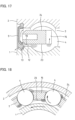
- Fig. 1 illustrates a grease-enclosed ball bearing according to a first embodiment of the present invention.
- the grease-enclosed ball bearing includes an inner ring 1; an outer ring 2 arranged radially outward of and coaxially with the inner ring 1; a plurality of balls 4 disposed in an annular bearing space 3 defined between the inner ring 1 and the outer ring 2 so as to be circumferentially spaced apart from each other; an annular seal member 5 disposed at one (left end in the drawing) of the axal ends of the bearing space 3 on both axial sides; an annular seal member 6 disposed at the other axial end (right end in the drawing) of the bearing space 3; and a cage 7 that keeps the circumferential intervals between the balls 4.
- the outer ring 2 has, in its inner periphery, an outer ring raceway groove 8 with which the balls 4 come into rolling contact; a pair of outer ring groove shoulders 9 located axially outward of the outer ring raceway groove 8; and a pair of seal fixing grooves 10 located axially outward of the respective outer ring groove shoulders 9.
- the outer ring raceway groove 8 circumferentially extends at the axial center of the inner periphery of the outer ring 2.
- the pair of outer ring groove shoulders 9 are bank-shaped portions circumferentially extending on both axial sides of the outer ring raceway groove 8.
- the seal fixing grooves 10 are circumferentially extending grooves formed axially outward of the respective outer ring groove shoulders 9 so as to be adjacent to the respective outer ring groove shoulders 9.
- the seal members 5 and 6 are fixedly fitted in the respective seal fixing grooves 10.
- the inner ring 1 has, in its outer periphery, an inner ring raceway groove 11 with which the balls 4 come into rolling contact; a pair of inner ring groove shoulders 12 located axially outward of the inner ring raceway groove 11; and a pair of sliding recesses 13 located axially outward of the respective inner ring groove shoulders 12.
- the inner ring raceway groove 11 circumferentially extends at the axial center of the outer periphery of the inner ring 1.
- the pair of inner ring groove shoulders 12 are bank-shaped portions circumferentially extending on both axial sides of the inner ring raceway groove 11.
- the sliding recesses 13 are circumferentially extending recesses formed axially outward of the respective inner ring groove shoulders 12 so as to be adjacent to the respective inner ring groove shoulders 12. Seal lips of the seal members 5 and 6 on the inner peripheries thereof are in sliding contact with the respective sliding recesses 13.
- seal members 5 and 6 contact-type seal members are exemplified in which the sealing lips of the seal members 5 and 6 on the inner peripheries thereof are in sliding contact with the respective sliding recesses 13, but non-contact type seal members may be used in which labyrinth gaps are defined between the sliding recesses 13 and the respective sealing lips of the seal members 5 and 6 on the inner peripheries thereof.
- the labyrinth gaps are minute gaps that can prevent entry of foreign matter, and that have, e.g., a width dimension of 0.5 mm or less.
- the balls 4 are radially sandwiched between the outer ring raceway groove 8 and the inner ring raceway groove 11.
- the ball bearing with the seals is a deep-groove ball bearing. That is, the outer ring raceway groove 8 is a circular arc-shaped groove having a concave circular arc-shaped cross section symmetrical in the axial direction, and the inner ring raceway groove 11 is also a circular arc-shaped groove having a concave circular arc-shaped cross section symmetrical in the axial direction.
- the circular arc radius of the cross section of the outer ring raceway groove 8 is slightly larger than the radius of each ball 4.
- the circular arc radius of the cross section of the inner ring raceway groove 11 is also slightly larger than the radius of each ball 4.
- the cage 7 is so-called a crown-type cage including a cage circular annular portion 14 circumferentially extending in a region axially sandwiched between a region through which the balls 4 pass and the seal member 5; and cage claws 15 each axially extending from the cage circular annular portion 14 so as to be located between the circumferentially adjacent pair of balls 4.
- the cage circular annular portion 14 and the cage claws 15 are formed as a seamless integral member made of a resin composition in which a fiber-reinforced material is added to a resin material.
- PA polyamide
- super engineering plastic As the resin material of the resin composition as its base, it is possible to use polyamide (PA) or super engineering plastic.
- PA46 polyamide 46
- PA66 polyamide 66
- PA9T polynonamethylene terephthalamide
- super engineering plastic it is possible to use polyether ether ketone (PEEK) or polyphenylene sulfide (PPS).
- PEEK polyether ether ketone
- PPS polyphenylene sulfide
- fiber-reinforced material added to the resin material it is possible to use glass fiber, carbon fiber, aramid fiber, or the like.
- the cage circular annular portion 14 has, on a cross section passing through the centers of the balls 4 and orthogonal to the circumferential direction, pocket bottoms 16 axially opposed to the respective balls 4; a circular annular portion radially outer surface 17 axially extending from the radially outer ends of the pocket bottoms 16; a circular annular portion radially inner surface 18 axially extending from the radially inner ends of the pocket bottoms 16; a seal opposed surface 19 axially opposed to the seal member 5 (see Fig. 1 ); and a grease release tapered surface 20 for grease release obliquely connecting the seal opposed surface 19 and the circular annular portion radially inner surface 18 together.
- the circular annular portion radially outer surface 17 is a cylindrical radially outer surface circumferentially extending at a position radially opposed to one of the outer ring groove shoulders 9 of the outer ring 2 on the inner periphery thereof.
- the circular annular portion radially inner surface 18 is a cylindrical radially inner surface circumferentially extending at a position radially opposed to one of the inner ring groove shoulders 12 of the inner ring 1 on the outer periphery thereof.
- the seal opposed surface 19 is a circular annular surface orthogonal to the axial direction, and circumferentially extending at a position axially opposed to the seal member 5.
- the radial gap between the outer periphery of the inner ring 1 and the circular annular portion radially inner surface 18 is larger than the radial gap between the inner periphery of the outer ring 2 and the circular annular portion radially outer surface 17.
- each cage claw 15 has a cantilevered structure having one axial end as a fixed end (root of the cage claw 15) fixed to the cage circular annular portion 14 and the other axial end as a free end (distal end of the cage claw 15).
- the cage claw 15 has an axial length longer than the radius of the ball 4 so as to extend to the side remote from the cage circular annular portion 14 beyond a pitch circle P connecting the centers of the plurality of balls 4.
- each cage claw 15 includes pocket surfaces 21 circumferentially opposed to the surfaces of the corresponding balls 4; a claw radially inner surface 23 circumferentially extending from the radially inner edges 22 of the pocket surfaces 21; and a claw radially outer surface 24 circumferentially extending from the radially outer edges of the pocket surfaces 21.
- Each pocket surface 21 has a concave spherical surface shape along the surface of the ball 4.
- the end of the pocket surface 21 closer to the cage circular annular portion 14 is connected to the pocket bottom 16 of the cage circular annular portion 14.
- the claw radially inner surface 23 is radially opposed to the inner ring raceway groove 11 and the inner ring groove shoulder 12 of the inner ring 1 on the outer periphery thereof.
- the claw radially inner surface 23 is constituted by an inclined radially inner surface portion 23a formed at the end of the cage claw 15 on the side of its root; and a non-inclined radially inner surface portion 23b connected to the side of the inclined radially inner surface portion 23a closer to the distal end of the cage claw 15.
- the inclined radially inner surface portion 23a is inclined to be displaced radially outward from the root of the cage claw 15 (side close to the cage circular annular portion 14) toward the distal end of the cage claw 15 (side remote from the cage circular annular portion 14).
- the inclined radially inner surface portion 23a may be a conical surface having a constant inclination along the axial direction, but in this embodiment, a funnel-shaped surface is used of which the inclination gradually increases toward the cage circular annular portion 14 along the axial direction.
- the inclination start position thereof is a position C at which the pocket bottom 16 and the circular annular portion radially inner surface 18 intersect with each other, so that the entire radially inner surface of the cage claw 15 is disposed radially outward of the circular annular portion radially inner surface 18.
- the non-inclined radially inner surface portion 23b is a cylindrical surface or a flat surface of which the radial position is constant, and does not change along the axial direction.
- the inclined radially inner surface portion 23a and the non-inclined radially inner surface portion 23b are connected to each other at a position axially close to the cage circular annular portion 14 beyond the position of the pitch circle P.
- the inner diameter of the claw radially inner surface 23 is smaller than the pitch circle P so that the radially inner edges 22 of the pocket surfaces 21 are located radially inward of the pitch circle P.
- the claw radially outer surface 24 is a cylindrical surface of which the radial position is constant, and does not change along the axial direction.
- the outer diameter of the claw radially outer surface 24 is larger than the pitch circle P.
- each cage claw 15 has a grease passage groove 25 radially extending through the cage claw 15 at the intermediate position between the circumferentially adjacent pair of balls 4.
- the grease passage groove 25 has a depth that allows the grease passage groove 25 to axially go into the cage claw 15 from the distal end of the cage claw 15 toward the root of the cage claw 15 beyond the pitch circle P (see Fig. 5 ).
- the grease is a lubricant containing a base oil such as a synthetic oil (synthetic hydrocarbon) or a mineral oil (refined from petroleum); and a thickener dispersed in the base oil so as to make the base oil into a semi-solid state.
- the base oil preferably has a kinematic viscosity of 45 to 50 mm 2 /s. If the base oil has a kinematic viscosity of 50 mm 2 /s or less, the grease is soft, and rotational torque of the ball bearing can be effectively reduced. Also, if the base oil has a kinematic viscosity of 45 mm 2 /s or more, it is possible to reduce scattering of the grease in the interior of the bearing during high-speed rotation, and thus to effectively reduce grease leakage from the bearing.
- the enclosed amount of grease enclosed is set to 38% or more of a total space volume obtained by subtracting the volume of the cage 7 and the volume of the plurality of balls 4 from the volume of the bearing space 3. Also, the enclosed amount of grease enclosed is set to 100% or more of a stationary space volume obtained by subtracting, from the volume of the bearing space 3, the volumes of the cage 7 and the passage region of the balls 4 during rotation of the bearing.
- the claw radially inner surface 23 is provided with an inclination for guiding grease that is displaced radially outward from the root of the cage claw 15 toward the distal end of the cage claw 15, it is possible to effectively prevent grease leakage even in a state where the enclosed amount of grease enclosed in the bearing space 3 is large.
- each cage claw 15 is provided with an inclination for guiding grease that is displaced radially outward from the root of the cage claw 15 toward the distal end of the cage claw 15. Therefore, when, as illustrated in Fig. 3 , due to rotation of the bearing, the grease on the surfaces of the balls 4 is scraped off by the cage claws 15, and accumulates on the claw radially inner surfaces 23, as illustrated in Fig.
- the grease accumulating on the claw radially inner surfaces 23 receives forces from roots of the cage claws 15 toward the distal ends of the cage claws 15 due to the inclinations for guiding grease provided on the claw radially inner surfaces 23 and the centrifugal force acting on the grease. Therefore, the grease scraped off from the surfaces of the balls 4 by the cage claws 15, and accumulating on the claw radially inner surfaces 23 is prevented from moving to the circular annular portion radially inner surface 18, and reaching the seal member 5, and grease leakage can be effectively prevented. At this time, the grease accumulating on the claw radially inner surfaces 23 is blocked by the inclined radially inner surface portions 23a of the claw radially inner surfaces 23 as illustrated in Fig. 8 .
- Fig. 7 illustrates the state of the grease scraped off by the cage claws 15, and accumulating on the claw radially inner surfaces 23 in a case where the enclosed amount of grease enclosed in the grease-enclosed ball bearing of the above embodiment is reduced.
- each cage claw 15 since, as illustrated in Fig. 5 , the claw radially inner surface 23 of each cage claw 15 is inclined from, as the inclination start position, a position C at which the pocket bottom 16 and the circular annular portion radially inner surface 18 intersect with each other (i.e., the position of the end of the cage claw 15 on the side of its root), it is possible to particularly effectively prevent the grease scraped off from the surfaces of the balls 4 by the cage claws 15 from moving to the circular annular portion radially inner surface 18.
- the claw radially inner surface 23 of each cage claw 15 is inclined from, as the inclination start position, the position C of the end of the cage claw 15 on the side of its root, the claw radially inner surface 23 has an inclination for guiding grease, at the position where the amount of the grease scraped off by the cage claws 15 is the largest. Therefore, it is possible to particularly effectively prevent the grease scraped off from the surfaces of the balls 4 by the cage claws 15 from moving to the circular annular portion radially inner surface 18.
- each cage claw 15 is disposed radially outward of the circular annular portion radially inner surface 18. Therefore, even if grease accumulates on any portion of the radially inner surface of the cage claw 15, the grease needs to move radially inward against the centrifugal force acting on the grease in order to move to the circular annular portion radially inner surface 18. Therefore, it is possible to effectively prevent the grease accumulating on the radially inner surfaces of the cage claws 15 from moving to the circular annular portion radially inner surface 18.
- each cage claw 15 is disposed radially outward of the circular annular portion radially inner surface 18. Therefore, compared to a comparative example in which, as illustrated in Fig. 17 , the radially inner surfaces of the cage claws 15 are disposed at the same radial position as the circular annular portion radially inner surface 18, it is possible to reduce the volumes of the cage claws 15, and to increase the amount of grease enclosed in the bearing space 3 accordingly.
- the circular annular portion radially inner surface 18 and the seal opposed surface 19 of the cage circular annular portion 14 are connected together via the oblique grease release tapered surface 20 so as not to directly intersect with each other. Therefore, even if grease accumulates on the circular annular portion radially inner surface 18, and the grease axially moves toward the seal member 5 along the circular annular portion radially inner surface 18, the grease moves radially outward along the grease release tapered surface 20 by the centrifugal force acting on the grease. Therefore, it is possible to prevent the grease from reaching the sealed portion between the seal member 5 and the inner ring 1.
- the radial gap between the outer periphery of the inner ring 1 and the circular annular portion radially inner surface 18 is large. Therefore, even if grease accumulates on the circular annular portion radially inner surface 18, and the grease axially moves toward the seal member 5 along the circular annular portion radially inner surface 18, the grease can be prevented from reaching the sealed portion between the seal member 5 and the inner ring 1.
- the grease-enclosed ball bearing of this embodiment has grease passage grooves 25 radially extending through the respective cage claws 15. Therefore, when the grease on the surfaces of the balls 4 is scraped off by the cage claws 15, accumulates on the claw radially inner surfaces 23, and overflows from the claw radially inner surfaces 23, the overflowing grease moves radially outward through the grease passage grooves 25 by a centrifugal force. Therefore, the grease in the interior of the bearing can be circulated without passing through the vicinity of the seal member 5, and the grease circulating in the interior of the bearing can be effectively prevented from reaching the sealed portion between the seal member 5 and the inner ring 1.
- each grease passage groove 25 has a depth that allows the grease passage groove 25 to axially go into the cage claw 15 from the distal end of the cage claw 15 toward the root of the cage claw 15 beyond the pitch circle P, compared to the comparative example shown in Fig. 17 , it is possible to reduce the volumes of the cage claws 15 due to formation of the grease passage grooves 25, and to increase the amount of grease enclosed in the bearing space 3.
- each cage claw 15 has an axial length longer than the radius of the ball 4, and the non-inclined radially inner surface portion 23b of the claw radially inner surface 23 of the cage claw 15 has an inner diameter smaller than the pitch circle P. Therefore, the cage claws 15 stably retain the balls 4 compared to a case where the inner diameter of the non-inclined radially inner surface portion 23b of the claw radially inner surface 23 of each cage claw is larger than the pitch circle P.
- the enclosed amount of grease enclosed is larger than in a normal grease-enclosed ball bearing, and in addition, grease leakage is less likely to occur. Therefore, it is possible to increase the bearing life (grease life) during which lubrication failure does not occur due to grease deterioration or the like. Therefore, it is possible to suitably use this grease-enclosed ball bearing as a bearing that supports a rotary shaft that rotates at a high speed, for example, a rotary shaft to which rotation of an electric motor of an electric vehicle is input, or a rotary shaft of a hybrid electric vehicle that uses an electric motor for an auxiliary driving force for the engine.
- this grease-enclosed ball bearing is particularly suitable for use as a ball bearing for high-speed rotation that rotates in a high-speed rotation range in which the dmn value (pitch circle diameter dm (mm) of the balls 4 ⁇ the number of rotations n (min -1 )) is one million or more.
- the portion of each cage claw 15 on the side of its distal end has a radial thickness smaller than that of the portion of the cage claw 15 on the side of its root. Therefore, it is possible to reduce radial deflection of the cage claw 15 generated when receiving a centrifugal force. Therefore, during high-speed rotation of the bearing, it is possible to reduce a change in the sizes of the gaps between the pocket surfaces 21 of the cage claws 15 and the surfaces of the balls 4 due to deflection of the cage claws 15.
- Figs. 21 and 22 each shows analysis results of the amount of radial displacement caused by deflection of the cage claw 15 while the bearing is rotating at a high speed, under the condition that the resin compositions constituting the cage claws 15 of Figs. 21 and 22 are the same.
- Fig. 21 as the grease-enclosed ball bearing of the comparative example shown in Fig. 16 , an analysis model was prepared in which the outer ring 2 has an outer diameter of 62 mm and the inner ring 1 has an inner diameter of 30 mm, and analysis was performed on the amount of radial displacement of each portion of the cage claw 15 due to deflection in the case where the inner ring 1 of the analysis model was rotated at 20,000 rpm.
- Fig. 21 as the grease-enclosed ball bearing of the comparative example shown in Fig. 16 , an analysis model was prepared in which the outer ring 2 has an outer diameter of 62 mm and the inner ring 1 has an inner diameter of 30 mm, and analysis was performed on the amount of radial
- an analysis model was prepared in which the outer ring 2 has an outer diameter of 62 mm and the inner ring 1 has an inner diameter of 30 mm, and analysis was performed on the amount of radial displacement of each portion of the cage claw 15 due to deflection in the case where the inner ring 1 of the analysis model was rotated at 20,000 rpm.
- the distal end of the cage claw 15 was radially displaced by about 0.8 mm due to deflection of the cage claw 15 caused by a centrifugal force.
- the radial displacement of the distal end of the cage claw 15 was reduced to less than 0.4 mm (about 1/2 of the comparative example). Also, analysis was performed using the same analysis models also in the case where the inner ring 1 was rotated at 30,000 rpm, and, as a result, the following was confirmed. With respect to the analysis model of the comparative example shown in Fig.21 , the distal end of the cage claw 15 was radially displaced by about 1.7 mm. In contrast thereto, with respect to the analysis model of the first embodiment shown in Fig. 22 , the radial displacement of the distal end of the cage claw 15 was reduced to about 0.7 mm.
- Figs. 9 to 11 illustrate a second embodiment of the present invention.
- the second embodiment is different from the first embodiment in that in the first embodiment, the circular annular portion radially inner surface 18 is a cylindrical surface of which the radial position does not change around the entire circumference, whereas in the second embedment, grease receiving recesses 26 are formed in the circular annular portion radially inner surface 18, but the second embodiment is the same as the first embodiment in the other structures. Therefore, the elements of the second embodiment corresponding to those of the first embodiment are hereinafter denoted by the same reference numerals, and the description thereof is omitted.
- the circular annular portion radially inner surface 18 has grease receiving recesses 26 each axially extending through the cage circular annular portion at the intermediate position between the circumferentially adjacent pair of balls 4.
- Each grease receiving recess 26 is shaped to gradually become shallow from the intermediate position between the circumferentially adjacent pair of balls 4 toward both circumferential sides.
- each grease receiving recess 26 is formed such that the radial position of the inner surface of the grease receiving recess 26 does not axially change.
- the grease receiving recess 26 is formed to axially extend through the cage circular annular portion 14, and partially enter the end of the cage claw 15 close to the cage circular annular portion 14.
- the inclination of each claw radially inner surface 23 has the same structure as the inclination thereof in the first embodiment.
- Fig. 12 illustrates a third embodiment of the present invention.
- the third embodiment is different from the first embodiment in that in the first embodiment, as illustrated in Fig. 8 , each pocket surface 21 and the claw radially inner surface 23 intersect with each other so as to form a sharp corner, whereas in the third embodiment, a chamfer 27 is disposed at the edge where each pocket surface 21 and the claw radially inner surface 23 intersect with each other, but the third embodiment is the same as the first embodiment in the other structures.
- a chamfer 27 having a size of 0.5 mm or more is disposed at the edge where each pocket surface 21 and the claw radially inner surface 23 intersect with each other.
- the chamfer 27 is a rounded chamfer having a circular arc-shaped cross section having a radius of 0.5 mm or more.
- a flat chamfer may be used which has a cross section in which the pocket surface 21 and the claw radially inner surface 23 are removed by a width of 0.5 mm or more along the respective surface directions of the pocket surface 21 and the claw radially inner surface 23, and an oblique straight portion is formed to connect these surfaces together.
- a chamfer 27 having a size of 0.5 mm or more is disposed at the edge where each pocket surface 21 and the claw radially inner surface 23 intersect with each other, it is possible to reduce grease scraping off action on the surfaces of the balls 4 due to the cage claws 15. Also, it is possible to effectively lubricate the surfaces of the balls 4 with the grease accumulating on the chamfers 27.
- grease receiving recesses 26 as used in the second embodiment may be additionally formed.
- a hollow annular member having an inner ring raceway groove 11 in the outer periphery is exemplified and described as the inner ring 1
- the inner ring 1 does not necessarily need to be a hollow annular member.
- a solid member (shaft body) having an inner ring raceway groove 11 which is directly formed in the outer periphery, and with which the balls 4 come into rolling contact may be used as the inner ring 1.
- an inner member having, in the outer periphery, an annular inner ring raceway groove with which the balls come into rolling contact can be used as the inner ring.
- a hollow annular member having an outer ring raceway groove 8 in the inner periphery is exemplified and described as the outer ring 2
- the outer ring 2 does not necessarily need to be a hollow annular member.
- a bearing housing having an outer ring raceway groove 8 which is directly formed in the inner periphery, and with which the balls 4 come into rolling contact may be used as the outer ring 2.
- an outer member having, in the inner periphery, an annular outer ring raceway groove with which the balls come into rolling contact can be used as the outer ring.
Landscapes
- Engineering & Computer Science (AREA)
- General Engineering & Computer Science (AREA)
- Mechanical Engineering (AREA)
- Rolling Contact Bearings (AREA)
- Sealing Of Bearings (AREA)
Abstract
Description
- The present invention relates to a grease-enclosed ball bearing in which grease is enclosed in an annular bearing space defined between an inner ring and an outer ring.
- As a bearing for supporting a rotary shaft of an automobile, an industrial machine, or the like, a grease-enclosed ball bearing is known in which grease is enclosed in an annular bearing space defined between an inner ring and an outer ring (for example, the below-identified
Patent Documents 1 to 3). - The below-identified
Patent Documents 1 to 3 each discloses a grease-enclosed ball bearing including an inner ring; an outer ring arranged radially outward of and coaxially with the inner ring; a plurality of balls disposed in a bearing space defined between the inner ring and the outer ring; and annular seal members disposed on the ends of the bearing space on both axial sides; grease enclosed in the bearing space; and a cage retaining the balls. As the cage, a so-called crown-type cage is used which includes a circumferentially extending cage circular annular portion; and cage claws having a cantilevered structure, and axially extending from the cage circular annular portion so as to be located between the respective circumferentially adjacent pairs of balls. -
- Patent Document 1:
Japanese Patent No. 6940993 - Patent Document 2:
Japanese Unexamined Patent Application Publication No. 2020-128786 - Patent Document 3:
Japanese Unexamined Patent Application Publication No. 2019-2498 - Nowadays, in the field of electric vehicles such as battery electric vehicles (EV) and hybrid electric vehicles (HEV), electric motors are rotated at a higher speed for a reduction in size and weight. A ball bearing supporting a rotary shaft to which rotation of such an electric motor is input is sometime used under the conditions that the dmn (ball pitch circle diameter dm(mm) X the number of rotations n (min-1)) value exceeds 2 million.
- The inventors of the present application considered using a grease-enclosed ball bearing as a bearing that supports a rotary shaft that rotates at a high speed, for example, a rotary shaft to which rotation of an electric motor of an electric vehicle is input. In a case where a grease-enclosed ball bearing supports a rotary shaft rotating at a high speed, it is necessary to increase a grease life in order to ensure a bearing life.
- Specifically, with respect to a grease-enclosed ball bearing, the bearing life (grease life) during which lubrication failure does not occur due to deterioration of the grease enclosed in the bearing space is normally shorter than the bearing life (fatigue life) during which abnormality does not occur due to fatigue of bearing components. Therefore, when studying the bearing life of the grease-enclosed ball bearing, the grease life is dominant. Also, in a case where the bearing is used for high-speed rotation, the total number of rotations of the bearing increases compared to a case where the bearing is used for low-speed rotation, even if the use time is the same in both cases.
- Therefore, if the grease-enclosed ball bearing is used as a bearing that supports a rotary shaft rotating at a high speed, increasing the grease life (i.e., increasing the total number of rotations of the bearing during the grease life) is required.
- As a way to increase the grease life, it is considered to increase the enclosed amount of grease enclosed in the bearing space so as to be larger than usual. However, if the enclosed amount of grease is simply increased, this only causes grease to leak easily, and, as a result, it is impossible to increase the amount of grease that can be actually used, and to increase the grease life.
- In view of the above, the inventors of the present application investigated a mechanism in which grease leakage occurs when the amount of grease enclosed in the bearing space is increased. As a result, the inventors of the present application discovered a mechanism of grease leakage in which, in a grease-enclosed ball bearing, when, due to rotation of the bearing, the grease on the surfaces of the balls is scraped off by the cage claws, and accumulates on the radially inner surfaces of the cage claws, and the grease accumulating on the radially inner surfaces of the cage claws increases, a portion of the grease moves to the radially inner surface of the cage circular annular portion, and when the grease accumulating on the radially inner surface of the cage circular annular portion increases, the grease overflowing from the radially inner surface of the cage circular annular portion reaches the contact or non-contact sealed portion between the seal member and the inner ring, and the grease reaching the sealed portion gradually leaks out of the bearing.
- Then, the inventors of the present application obtained the idea that if, when the grease on the surfaces of the balls is scraped off by the cage claws, and accumulates on the radially surfaces of the cage claws, the grease accumulating on the radially inner surfaces of the cage claws can be prevented from moving to the radially inner surface of the cage circular annular portion, grease leakage does not occur even when the amount of grease enclosed in the bearing space is increased.
- It is an object of the present invention to provide a grease-enclosed ball bearing in which grease leakage can be effectively prevented.
- In order to achieve the above object, the present invention provides a grease-enclosed ball bearing comprising: an inner ring; an outer ring arranged radially outwardly of, and coaxially with, the inner ring; a plurality of balls disposed in an annular bearing space defined between the inner ring and the outer ring; an annular seal member disposed at one axial end of the bearing space; grease enclosed in the bearing space; and a cage retaining the balls, wherein the cage includes: a cage circular annular portion that circumferentially extends; and cage claws having a cantilevered structure, and axially extending from the cage circular annular portion so as to be located between respective circumferentially adjacent pairs of the balls, and wherein each of the cage claws has: pocket surfaces opposed to surfaces of corresponding ones of the balls, respectively; and a claw radially inner surface circumferentially extending from radially inner edges of the pocket surfaces so as to be opposed to an outer periphery of the inner ring, characterized in that the claw radially inner surface of each of the cage claws is provided with an inclination for guiding grease that is displaced radially outward from a root of the cage claw toward a distal end of the cage claw.
- With this arrangement, due to the inclinations for guiding grease disposed on the claw radially inner surfaces and the centrifugal force acting on grease, it is possible to prevent the grease accumulating on the claw radially inner surfaces from moving to the radially inner surface of the cage circular annular portion. Therefore, the grease scraped off by the cage claws from the surfaces of the balls, and accumulating on the claw radially inner surfaces is prevented from reaching the seal member, and grease leakage can be effectively prevented.
- It is preferable that the cage circular annular portion has, on a cross section passing through centers of the balls and orthogonal to a circumferential direction, pocket bottoms axially opposed to the respective balls; and a circular annular portion radially inner surface axially extending from radially inner ends of the pocket bottoms, and radially opposed to the outer periphery of the inner ring, and an inclination start positions of the inclination of the claw radially inner surface of each of the cage claws is a position where a corresponding one of the pocket bottoms and the circular annular portion radially inner surface intersect with each other.
- With this arrangement, since the claw radially inner surface of each cage claw is inclined from, as the inclination start position, a position at which the pocket bottom and the circular annular portion radially inner surface intersect with each other (i.e., the position of the end of the cage claw on the side of its root), it is possible to particularly effectively prevent the grease scraped off from the surfaces of the balls by the cage claws from moving to the circular annular portion radially inner surface. That is, since, due to rotation of the bearing, the grease adhering to the inner periphery of the outer ring and the outer periphery of the inner ring is pushed away to both axial sides by the balls, the adhesion amount of the grease adhering to the surfaces of the balls is larger at the portions on both axial sides than at the portions in contact with the axial centers of the outer ring raceway surface and the inner ring raceway surface, and the amount of the grease scraped off from the surfaces of the balls by the cage claws is normally the largest at the positions of the ends of the cage claws on the sides of their roots. Since the claw radially inner surface of each cage claw is inclined from, as the inclination start position, the position of the end of the cage claw on the side of its root, the claw radially inner surface has an inclination for guiding grease, at the position where the amount of the grease scraped off by the cage claws is the largest. Therefore, it is possible to particularly effectively prevent the grease scraped off from the surfaces of the balls by the cage claws from moving to the circular annular portion radially inner surface.
- It is preferable that the cage radially inner surface of each of the cage claws is entirely disposed radially outward of the circular annular portion radially inner surface.
- With this arrangement, even if grease accumulates on any portion of the radially inner surface of each cage claw, the grease needs to move radially inward against the centrifugal force acting on the grease in order to move to the circular annular portion radially inner surface. Therefore, it is possible to effectively prevent the grease accumulating on the radially inner surfaces of the cage claws from moving to the circular annular portion radially inner surface. Also, if the entire radially inner surface of each cage claw is disposed radially outward of the circular annular portion radially inner surface, it is possible to reduce the volumes of the cage claws, and to increase the amount of grease enclosed in the bearing space accordingly.
- It is preferable that the cage circular annular portion further has: a seal opposed surface axially opposed to the seal member; and a grease release tapered surface obliquely connecting the seal opposed surface and the circular annular portion radially inner surface together.
- With this arrangement, the circular annular portion radially inner surface and the seal opposed surface of the cage circular annular portion are connected together via the oblique grease release tapered surface so as not to directly intersect with each other. Therefore, even if grease accumulates on the circular annular portion radially inner surface, and the grease axially moves toward the seal member along the circular annular portion radially inner surface, the grease moves radially outward along the grease release tapered surface by the centrifugal force acting on the grease. Therefore, it is possible to prevent the grease from reaching the sealed portion between the seal member and the inner ring.
- It is preferable that the cage circular annular portion further has a circular annular portion radially outer surface radially opposed to an inner periphery of the outer ring, and a radial gap between the outer periphery of the inner ring and the circular annular portion radially inner surface is larger than a radial gap between the inner periphery of the outer ring and the circular annular portion radially outer surface.
- With this arrangement, since the radial gap between the outer periphery of the inner ring and the circular annular portion radially inner surface is large, even if grease accumulates on the circular annular portion radially inner surface, and the grease axially moves toward the seal member along the circular annular portion radially inner surface, the grease can be prevented from reaching the sealed portion between the seal member and the inner ring.
- The circular annular portion radially inner surface is preferably formed with grease receiving recesses each axially extending through the cage circular annular portion at an intermediate position between a corresponding circumferentially adjacent pair of the balls.
- With this arrangement, even if grease adheres to the circular annular portion radially inner surface, it is possible to prevent the grease from reaching the sealed portion between the seal member and the inner ring by introducing the grease into the grease receiving recesses.
- Each of the cage claws is preferably formed with a grease passage groove radially extending through the cage claw at the intermediate position between the corresponding circumferentially adjacent pair of the balls, the grease passage groove having a depth that allows the grease passage groove to axially go into the cage claw from the distal end of the cage claw toward the root of the cage claw beyond a pitch circle connecting the centers of the balls.
- With this arrangement, when, due to rotation of the bearing, the grease on the surfaces of the balls is scraped off by the cage claws, accumulates on the claw radially inner surfaces, and overflows from the claw radially inner surfaces, the overflowing grease moves radially outward through the grease passage grooves by a centrifugal force. Therefore, the grease in the interior of the bearing can be circulated without passing through the vicinity of the seal member, and the grease circulating in the interior of the bearing can be effectively prevented from reaching the sealed portion between the seal member and the inner ring. Also, it is possible to reduce the volumes of the cage claws due to formation of the grease passage grooves, and thus to increase the amount of grease enclosed in the bearing space.
- It is preferable that axial lengths of the cage claws are longer than radii of the balls, and the claw radially inner surface of each of the cage claws has an inner diameter smaller than the pitch circle, which connects the centers of the balls, such that the radially inner edges of the pocket surfaces of the cage claw are located radially inward of the pitch circle.
- With this arrangement, the balls are stably retained by the cage claws.
- A chamfer having a size of 0.5 mm or more is preferably disposed at an edge where each of the pocket surfaces of each of the cage claws and the claw radially inner surface of the cage claw intersect with each other.
- With this arrangement, it is possible to reduce grease scraping off action on the surfaces of the balls due to the cage claws. Also, it is possible to effectively lubricate the surfaces of the balls with the grease accumulating on the chamfers.
- Each of the cage claws is preferably formed with grease grooves radially extending to cross the respective pocket surfaces of the cage claw.
- With this arrangement, it is possible to effectively lubricate the surfaces of the balls with the grease accumulating on the grease grooves and the grease accumulating on the claw radially inner surfaces.
- The cage can be formed of a resin composition in which a fiber-reinforced material is added to a resin material.
- An enclosed amount of the grease enclosed is preferably set to 38% or more of a total space volume obtained by subtracting a volume of the cage and a volume of the balls from a volume of the bearing space.
- With this arrangement, the enclosed amount of grease enclosed is larger than in a normal grease-enclosed ball bearing, and in addition, grease leakage is less likely to occur. Therefore, it is possible to increase the bearing life (grease life) during which lubrication failure does not occur due to grease deterioration or the like.
- The enclosed amount of the grease enclosed is preferably set to 100% or more of a stationary space volume obtained by subtracting, from the volume of the bearing space, the volume of the cage and a volume of a passage region of the balls during rotation of the bearing.
- With this arrangement, the enclosed amount of grease enclosed is larger than in a normal grease-enclosed ball bearing, and in addition, grease leakage is less likely to occur. Therefore, it is possible to increase the grease life.
- In the grease-enclosed ball bearing of the present invention, due to the inclinations for guiding grease disposed on the claw radially inner surfaces and the centrifugal force acting on grease, it is possible to prevent the grease accumulating on the claw radially inner surfaces from moving to the radially inner surface of the cage circular annular portion. Therefore, the grease scraped off by the cage claws from the surfaces of the balls, and accumulating on the claw radially inner surfaces is prevented from reaching the seal member, and grease leakage can be effectively prevented.
-
-
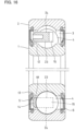
Fig. 1 is a sectional view of a grease-enclosed ball bearing according to a first embodiment of the present invention. -
Fig. 2 is an enlarged sectional view illustrating a cage inFig. 1 and the vicinity thereof. -
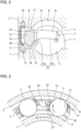
Fig. 3 is a sectional view of the grease-enclosed ball bearing inFig. 2 taken along a plane passing through the centers of balls and orthogonal to the axial direction. -
Fig. 4 is a right-side view of the cage illustrated inFig. 2 . -
Fig. 5 is a sectional view taken along line V-V inFig. 4 . -
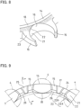
Fig. 6 is a perspective view of the cage inFig. 1 when seen from the side of cage claws. -
Fig. 7 is an enlarged perspective view of the cage illustrating a state of the grease accumulating on claw radially inner surfaces when the amount of the grease enclosed in the grease-enclosed ball bearing inFig. 1 is reduced. -
Fig. 8 is an enlarged perspective view of the cage illustrating a state of the grease accumulating on the claw radially inner surfaces of the grease-enclosed ball bearing inFig. 1 . -
Fig. 9 is a view illustrating a second embodiment of the present invention, and corresponding toFig. 4 . -
Fig. 10 is a sectional view taken along line X-X inFig. 9 . -
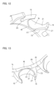
Fig. 11 is an enlarged perspective view of a cage illustrated inFig. 9 when seen from the radially inner side. -
Fig. 12 is a perspective view of a cage of a grease-enclosed ball bearing according to a third embodiment of the present invention when seen from the radially inner side. -
Fig. 13 is an enlarged perspective view illustrating a variation of the cage inFig. 12 in which grease receiving recesses are disposed in the cage. -
Fig. 14 is a perspective view of a cage of a grease-enclosed ball bearing according to a fourth embodiment of the present invention when seen from the radially inner side. -
Fig. 15 is a sectional view of a cage of a grease-enclosed ball bearing according to a fifth embodiment of the present invention taken along a plane passing through the centers of balls and orthogonal to the axial direction. -
Fig. 16 is a sectional view of a grease-enclosed ball bearing of a comparative example, the sectional view corresponding toFig. 1 . -
Fig. 17 is an enlarged sectional view illustrating a cage inFig. 16 and the vicinity thereof. -
Fig. 18 is a sectional view of the grease-enclosed ball bearing inFig. 17 taken along a plane passing through the centers of balls and orthogonal to the axial direction. -
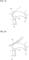
Fig. 19 is an enlarged perspective view of the cage illustrating a state of the grease accumulating on claw radially inner surfaces of the grease-enclosed ball bearing inFig. 16 . -
Fig. 20 is an enlarged perspective view of the cage illustrating a state of the grease accumulating on the claw radially inner surfaces when the amount of the grease enclosed in the grease-enclosed ball bearing inFig. 16 is increased. -
Fig. 21 is a view illustrating analysis results of the amount of radial displacement due to deflection of a cage claw caused when the grease-enclosed ball bearing inFig. 16 is rotated at a high speed. -
Fig. 22 is a view illustrating analysis results of the amount of radial displacement due to deflection of a cage claw caused when the grease-enclosed ball bearing inFig. 1 is rotated at a high speed. -
Fig. 1 illustrates a grease-enclosed ball bearing according to a first embodiment of the present invention. The grease-enclosed ball bearing includes aninner ring 1; anouter ring 2 arranged radially outward of and coaxially with theinner ring 1; a plurality ofballs 4 disposed in anannular bearing space 3 defined between theinner ring 1 and theouter ring 2 so as to be circumferentially spaced apart from each other; anannular seal member 5 disposed at one (left end in the drawing) of the axal ends of thebearing space 3 on both axial sides; anannular seal member 6 disposed at the other axial end (right end in the drawing) of thebearing space 3; and acage 7 that keeps the circumferential intervals between theballs 4. - The
outer ring 2 has, in its inner periphery, an outerring raceway groove 8 with which theballs 4 come into rolling contact; a pair of outerring groove shoulders 9 located axially outward of the outerring raceway groove 8; and a pair ofseal fixing grooves 10 located axially outward of the respective outer ring groove shoulders 9. The outerring raceway groove 8 circumferentially extends at the axial center of the inner periphery of theouter ring 2. The pair of outerring groove shoulders 9 are bank-shaped portions circumferentially extending on both axial sides of the outerring raceway groove 8. Theseal fixing grooves 10 are circumferentially extending grooves formed axially outward of the respective outerring groove shoulders 9 so as to be adjacent to the respective outer ring groove shoulders 9. Theseal members seal fixing grooves 10. - The
inner ring 1 has, in its outer periphery, an innerring raceway groove 11 with which theballs 4 come into rolling contact; a pair of inner ring groove shoulders 12 located axially outward of the innerring raceway groove 11; and a pair of slidingrecesses 13 located axially outward of the respective inner ring groove shoulders 12. The innerring raceway groove 11 circumferentially extends at the axial center of the outer periphery of theinner ring 1. The pair of inner ring groove shoulders 12 are bank-shaped portions circumferentially extending on both axial sides of the innerring raceway groove 11. The sliding recesses 13 are circumferentially extending recesses formed axially outward of the respective inner ring groove shoulders 12 so as to be adjacent to the respective inner ring groove shoulders 12. Seal lips of theseal members - As the
seal members seal members recesses 13, but non-contact type seal members may be used in which labyrinth gaps are defined between the slidingrecesses 13 and the respective sealing lips of theseal members - The
balls 4 are radially sandwiched between the outerring raceway groove 8 and the innerring raceway groove 11. The ball bearing with the seals is a deep-groove ball bearing. That is, the outerring raceway groove 8 is a circular arc-shaped groove having a concave circular arc-shaped cross section symmetrical in the axial direction, and the innerring raceway groove 11 is also a circular arc-shaped groove having a concave circular arc-shaped cross section symmetrical in the axial direction. The circular arc radius of the cross section of the outerring raceway groove 8 is slightly larger than the radius of eachball 4. The circular arc radius of the cross section of the innerring raceway groove 11 is also slightly larger than the radius of eachball 4. - The
cage 7 is so-called a crown-type cage including a cage circularannular portion 14 circumferentially extending in a region axially sandwiched between a region through which theballs 4 pass and theseal member 5; andcage claws 15 each axially extending from the cage circularannular portion 14 so as to be located between the circumferentially adjacent pair ofballs 4. The cage circularannular portion 14 and thecage claws 15 are formed as a seamless integral member made of a resin composition in which a fiber-reinforced material is added to a resin material. - As the resin material of the resin composition as its base, it is possible to use polyamide (PA) or super engineering plastic. As the polyamide, it is possible to use polyamide 46 (PA46), polyamide 66 (PA66), polynonamethylene terephthalamide (PA9T), or the like. As the super engineering plastic, it is possible to use polyether ether ketone (PEEK) or polyphenylene sulfide (PPS). As the fiber-reinforced material added to the resin material, it is possible to use glass fiber, carbon fiber, aramid fiber, or the like.
- As illustrated in
Fig. 5 , the cage circularannular portion 14 has, on a cross section passing through the centers of theballs 4 and orthogonal to the circumferential direction,pocket bottoms 16 axially opposed to therespective balls 4; a circular annular portion radiallyouter surface 17 axially extending from the radially outer ends of thepocket bottoms 16; a circular annular portion radiallyinner surface 18 axially extending from the radially inner ends of thepocket bottoms 16; a seal opposedsurface 19 axially opposed to the seal member 5 (seeFig. 1 ); and a grease release taperedsurface 20 for grease release obliquely connecting the seal opposedsurface 19 and the circular annular portion radiallyinner surface 18 together. - As illustrated in
Fig. 2 , the circular annular portion radiallyouter surface 17 is a cylindrical radially outer surface circumferentially extending at a position radially opposed to one of the outerring groove shoulders 9 of theouter ring 2 on the inner periphery thereof. The circular annular portion radiallyinner surface 18 is a cylindrical radially inner surface circumferentially extending at a position radially opposed to one of the inner ring groove shoulders 12 of theinner ring 1 on the outer periphery thereof. The seal opposedsurface 19 is a circular annular surface orthogonal to the axial direction, and circumferentially extending at a position axially opposed to theseal member 5. The radial gap between the outer periphery of theinner ring 1 and the circular annular portion radiallyinner surface 18 is larger than the radial gap between the inner periphery of theouter ring 2 and the circular annular portion radiallyouter surface 17. - As illustrated in
Fig. 5 , eachcage claw 15 has a cantilevered structure having one axial end as a fixed end (root of the cage claw 15) fixed to the cage circularannular portion 14 and the other axial end as a free end (distal end of the cage claw 15). Thecage claw 15 has an axial length longer than the radius of theball 4 so as to extend to the side remote from the cage circularannular portion 14 beyond a pitch circle P connecting the centers of the plurality ofballs 4. - As illustrated in
Figs. 4 and 5 , eachcage claw 15 includes pocket surfaces 21 circumferentially opposed to the surfaces of thecorresponding balls 4; a claw radiallyinner surface 23 circumferentially extending from the radiallyinner edges 22 of the pocket surfaces 21; and a claw radiallyouter surface 24 circumferentially extending from the radially outer edges of the pocket surfaces 21. Eachpocket surface 21 has a concave spherical surface shape along the surface of theball 4. As illustrated inFig. 5 , the end of thepocket surface 21 closer to the cage circularannular portion 14 is connected to thepocket bottom 16 of the cage circularannular portion 14. As illustrated inFig. 2 , the claw radiallyinner surface 23 is radially opposed to the innerring raceway groove 11 and the innerring groove shoulder 12 of theinner ring 1 on the outer periphery thereof. - As illustrated in
Fig. 5 , the claw radiallyinner surface 23 is constituted by an inclined radiallyinner surface portion 23a formed at the end of thecage claw 15 on the side of its root; and a non-inclined radiallyinner surface portion 23b connected to the side of the inclined radiallyinner surface portion 23a closer to the distal end of thecage claw 15. The inclined radiallyinner surface portion 23a is inclined to be displaced radially outward from the root of the cage claw 15 (side close to the cage circular annular portion 14) toward the distal end of the cage claw 15 (side remote from the cage circular annular portion 14). The inclined radiallyinner surface portion 23a may be a conical surface having a constant inclination along the axial direction, but in this embodiment, a funnel-shaped surface is used of which the inclination gradually increases toward the cage circularannular portion 14 along the axial direction. - With respect to the inclination of the inclined radially
inner surface portion 23a, the inclination start position thereof is a position C at which thepocket bottom 16 and the circular annular portion radiallyinner surface 18 intersect with each other, so that the entire radially inner surface of thecage claw 15 is disposed radially outward of the circular annular portion radiallyinner surface 18. The non-inclined radiallyinner surface portion 23b is a cylindrical surface or a flat surface of which the radial position is constant, and does not change along the axial direction. The inclined radiallyinner surface portion 23a and the non-inclined radiallyinner surface portion 23b are connected to each other at a position axially close to the cage circularannular portion 14 beyond the position of the pitch circle P. The inner diameter of the claw radially inner surface 23 (inner diameter of the non-inclined radiallyinner surface portion 23b in the drawing) is smaller than the pitch circle P so that the radiallyinner edges 22 of the pocket surfaces 21 are located radially inward of the pitch circle P. - The claw radially
outer surface 24 is a cylindrical surface of which the radial position is constant, and does not change along the axial direction. The outer diameter of the claw radiallyouter surface 24 is larger than the pitch circle P. - As illustrated in
Figs. 3 and6 , eachcage claw 15 has agrease passage groove 25 radially extending through thecage claw 15 at the intermediate position between the circumferentially adjacent pair ofballs 4. As illustrated inFig. 2 , thegrease passage groove 25 has a depth that allows thegrease passage groove 25 to axially go into thecage claw 15 from the distal end of thecage claw 15 toward the root of thecage claw 15 beyond the pitch circle P (seeFig. 5 ). - Grease is enclosed in the
annular bearing space 3 illustrated inFig. 1 , which is defined by theinner ring 1 and theouter ring 2 and theseal members - In the grease-enclosed ball bearing of this embodiment, the enclosed amount of grease enclosed is set to 38% or more of a total space volume obtained by subtracting the volume of the
cage 7 and the volume of the plurality ofballs 4 from the volume of thebearing space 3. Also, the enclosed amount of grease enclosed is set to 100% or more of a stationary space volume obtained by subtracting, from the volume of thebearing space 3, the volumes of thecage 7 and the passage region of theballs 4 during rotation of the bearing. - In the grease-enclosed ball bearing of this embodiment, as illustrated in
Figs. 2 and5 , since, at eachcage claw 15, the claw radiallyinner surface 23 is provided with an inclination for guiding grease that is displaced radially outward from the root of thecage claw 15 toward the distal end of thecage claw 15, it is possible to effectively prevent grease leakage even in a state where the enclosed amount of grease enclosed in thebearing space 3 is large. - That is, a comparative example is now assumed in which, as illustrated in
Figs. 16 to 18 , the claw radiallyinner surfaces 23 are not inclined, and the radial positions of the claw radiallyinner surfaces 23 are constant and do not change along the axial direction. In this case, as illustrated inFig. 18 , due to rotation of the bearing, the grease on the surfaces of theballs 4 is scraped off by thecage claws 15, and accumulates on the claw radiallyinner surfaces 23 and the claw radiallyouter surfaces 24. In a normal grease-enclosed ball bearing, since the enclosed amount of grease enclosed in thebearing space 3 is relatively small, as illustrated inFig. 19 , the grease scraped off by thecage claws 15 remains there, and does not normally move to the circular annular portion radiallyinner surface 18. However, when the enclosed amount of grease enclosed in thebearing space 3 is increased, the grease scraped off by thecage claws 15 and accumulating on the claw radiallyinner surfaces 23 increases as illustrated inFig. 17 , and a portion of the grease moves to the circular annular portion radiallyinner surface 18. When the grease accumulating on the circular annular portion radiallyinner surface 18 increases, the grease overflowing from the circular annular portion radiallyinner surface 18 reaches the sealed portion between theseal member 5 and the inner ring 1 (sliding contact portion between the seal lip of theseal member 5 on the inner periphery thereof and one of the slidingrecesses 13 of theinner ring 1 in the outer periphery thereof), and the grease reaching this sealed portion could gradually leak out of the bearing. At this time, as illustrated inFig. 17 , when the grease accumulating on the circular annular portion radiallyinner surface 18 comes into contact with one of the inner ring groove shoulders 12, the grease adheres to the entire circular annular portion radiallyinner surface 18 as illustrated inFig. 20 . - In contrast thereto, in the grease-enclosed ball bearing of the above embodiment, as illustrated in
Figs. 2 and5 , the claw radiallyinner surface 23 of eachcage claw 15 is provided with an inclination for guiding grease that is displaced radially outward from the root of thecage claw 15 toward the distal end of thecage claw 15. Therefore, when, as illustrated inFig. 3 , due to rotation of the bearing, the grease on the surfaces of theballs 4 is scraped off by thecage claws 15, and accumulates on the claw radiallyinner surfaces 23, as illustrated inFig. 2 , the grease accumulating on the claw radiallyinner surfaces 23 receives forces from roots of thecage claws 15 toward the distal ends of thecage claws 15 due to the inclinations for guiding grease provided on the claw radiallyinner surfaces 23 and the centrifugal force acting on the grease. Therefore, the grease scraped off from the surfaces of theballs 4 by thecage claws 15, and accumulating on the claw radiallyinner surfaces 23 is prevented from moving to the circular annular portion radiallyinner surface 18, and reaching theseal member 5, and grease leakage can be effectively prevented. At this time, the grease accumulating on the claw radiallyinner surfaces 23 is blocked by the inclined radiallyinner surface portions 23a of the claw radiallyinner surfaces 23 as illustrated inFig. 8 .Fig. 7 illustrates the state of the grease scraped off by thecage claws 15, and accumulating on the claw radiallyinner surfaces 23 in a case where the enclosed amount of grease enclosed in the grease-enclosed ball bearing of the above embodiment is reduced. - Also, in the grease-enclosed ball bearing of this embodiment, since, as illustrated in
Fig. 5 , the claw radiallyinner surface 23 of eachcage claw 15 is inclined from, as the inclination start position, a position C at which thepocket bottom 16 and the circular annular portion radiallyinner surface 18 intersect with each other (i.e., the position of the end of thecage claw 15 on the side of its root), it is possible to particularly effectively prevent the grease scraped off from the surfaces of theballs 4 by thecage claws 15 from moving to the circular annular portion radiallyinner surface 18. - That is, since the grease adhering to the outer
ring raceway groove 8 and the innerring raceway groove 11 illustrated inFig. 2 is pushed away to both axial sides by theballs 4, the adhesion amount of the grease adhering to the surfaces of theballs 4 is larger at the portions on both axial sides than at the portions in contact with the axial centers of the outerring raceway groove 8 and the innerring raceway groove 11, and the amount of the grease scraped off from the surfaces of theballs 4 by thecage claws 15 is normally the largest at the positions of the ends of thecage claws 15 on the sides of their roots. Since, as illustrated inFig. 5 , the claw radiallyinner surface 23 of eachcage claw 15 is inclined from, as the inclination start position, the position C of the end of thecage claw 15 on the side of its root, the claw radiallyinner surface 23 has an inclination for guiding grease, at the position where the amount of the grease scraped off by thecage claws 15 is the largest. Therefore, it is possible to particularly effectively prevent the grease scraped off from the surfaces of theballs 4 by thecage claws 15 from moving to the circular annular portion radiallyinner surface 18. - Also, in the grease-enclosed ball bearing of this embodiment, as illustrated in
Figs. 2 and5 , the entire radially inner surface of eachcage claw 15 is disposed radially outward of the circular annular portion radiallyinner surface 18. Therefore, even if grease accumulates on any portion of the radially inner surface of thecage claw 15, the grease needs to move radially inward against the centrifugal force acting on the grease in order to move to the circular annular portion radiallyinner surface 18. Therefore, it is possible to effectively prevent the grease accumulating on the radially inner surfaces of thecage claws 15 from moving to the circular annular portion radiallyinner surface 18. - Also, in the grease-enclosed ball bearing of this embodiment, as illustrated in
Fig. 2 , the entire radially inner surface of eachcage claw 15 is disposed radially outward of the circular annular portion radiallyinner surface 18. Therefore, compared to a comparative example in which, as illustrated inFig. 17 , the radially inner surfaces of thecage claws 15 are disposed at the same radial position as the circular annular portion radiallyinner surface 18, it is possible to reduce the volumes of thecage claws 15, and to increase the amount of grease enclosed in thebearing space 3 accordingly. - Also, in the grease-enclosed ball bearing of this embodiment, as illustrated in
Fig. 2 , the circular annular portion radiallyinner surface 18 and the seal opposedsurface 19 of the cage circularannular portion 14 are connected together via the oblique grease release taperedsurface 20 so as not to directly intersect with each other. Therefore, even if grease accumulates on the circular annular portion radiallyinner surface 18, and the grease axially moves toward theseal member 5 along the circular annular portion radiallyinner surface 18, the grease moves radially outward along the grease release taperedsurface 20 by the centrifugal force acting on the grease. Therefore, it is possible to prevent the grease from reaching the sealed portion between theseal member 5 and theinner ring 1. - Also, in the grease-enclosed ball bearing of this embodiment, as illustrated in
Fig. 2 , the radial gap between the outer periphery of theinner ring 1 and the circular annular portion radiallyinner surface 18 is large. Therefore, even if grease accumulates on the circular annular portion radiallyinner surface 18, and the grease axially moves toward theseal member 5 along the circular annular portion radiallyinner surface 18, the grease can be prevented from reaching the sealed portion between theseal member 5 and theinner ring 1. - Also, as illustrated in
Figs. 2 and 3 , the grease-enclosed ball bearing of this embodiment hasgrease passage grooves 25 radially extending through therespective cage claws 15. Therefore, when the grease on the surfaces of theballs 4 is scraped off by thecage claws 15, accumulates on the claw radiallyinner surfaces 23, and overflows from the claw radiallyinner surfaces 23, the overflowing grease moves radially outward through thegrease passage grooves 25 by a centrifugal force. Therefore, the grease in the interior of the bearing can be circulated without passing through the vicinity of theseal member 5, and the grease circulating in the interior of the bearing can be effectively prevented from reaching the sealed portion between theseal member 5 and theinner ring 1. - Also, in the grease-enclosed ball bearing of this embodiment, since each
grease passage groove 25 has a depth that allows thegrease passage groove 25 to axially go into thecage claw 15 from the distal end of thecage claw 15 toward the root of thecage claw 15 beyond the pitch circle P, compared to the comparative example shown inFig. 17 , it is possible to reduce the volumes of thecage claws 15 due to formation of thegrease passage grooves 25, and to increase the amount of grease enclosed in thebearing space 3. - Also, in the grease-enclosed ball bearing of this embodiment, as illustrated in
Fig. 5 , eachcage claw 15 has an axial length longer than the radius of theball 4, and the non-inclined radiallyinner surface portion 23b of the claw radiallyinner surface 23 of thecage claw 15 has an inner diameter smaller than the pitch circle P. Therefore, thecage claws 15 stably retain theballs 4 compared to a case where the inner diameter of the non-inclined radiallyinner surface portion 23b of the claw radiallyinner surface 23 of each cage claw is larger than the pitch circle P. - Also, in the grease-enclosed ball bearing of this embodiment, the enclosed amount of grease enclosed is larger than in a normal grease-enclosed ball bearing, and in addition, grease leakage is less likely to occur. Therefore, it is possible to increase the bearing life (grease life) during which lubrication failure does not occur due to grease deterioration or the like. Therefore, it is possible to suitably use this grease-enclosed ball bearing as a bearing that supports a rotary shaft that rotates at a high speed, for example, a rotary shaft to which rotation of an electric motor of an electric vehicle is input, or a rotary shaft of a hybrid electric vehicle that uses an electric motor for an auxiliary driving force for the engine. Specifically, this grease-enclosed ball bearing is particularly suitable for use as a ball bearing for high-speed rotation that rotates in a high-speed rotation range in which the dmn value (pitch circle diameter dm (mm) of the
balls 4 × the number of rotations n (min-1)) is one million or more. - Also, in the grease-enclosed ball bearing of this embodiment, the portion of each
cage claw 15 on the side of its distal end has a radial thickness smaller than that of the portion of thecage claw 15 on the side of its root. Therefore, it is possible to reduce radial deflection of thecage claw 15 generated when receiving a centrifugal force. Therefore, during high-speed rotation of the bearing, it is possible to reduce a change in the sizes of the gaps between the pocket surfaces 21 of thecage claws 15 and the surfaces of theballs 4 due to deflection of thecage claws 15. -
Figs. 21 and 22 each shows analysis results of the amount of radial displacement caused by deflection of thecage claw 15 while the bearing is rotating at a high speed, under the condition that the resin compositions constituting thecage claws 15 ofFigs. 21 and 22 are the same. With respect toFig. 21 , as the grease-enclosed ball bearing of the comparative example shown inFig. 16 , an analysis model was prepared in which theouter ring 2 has an outer diameter of 62 mm and theinner ring 1 has an inner diameter of 30 mm, and analysis was performed on the amount of radial displacement of each portion of thecage claw 15 due to deflection in the case where theinner ring 1 of the analysis model was rotated at 20,000 rpm. With respect toFig. 22 , as the grease-enclosed ball bearing of the first embodiment shown inFig. 1 , an analysis model was prepared in which theouter ring 2 has an outer diameter of 62 mm and theinner ring 1 has an inner diameter of 30 mm, and analysis was performed on the amount of radial displacement of each portion of thecage claw 15 due to deflection in the case where theinner ring 1 of the analysis model was rotated at 20,000 rpm. When comparingFigs. 21 and 22 , the following was confirmed. With respect to the comparative example shown inFig. 21 , the distal end of thecage claw 15 was radially displaced by about 0.8 mm due to deflection of thecage claw 15 caused by a centrifugal force. In contrast thereto, with respect to the first embodiment shown inFig. 22 , the radial displacement of the distal end of thecage claw 15 was reduced to less than 0.4 mm (about 1/2 of the comparative example). Also, analysis was performed using the same analysis models also in the case where theinner ring 1 was rotated at 30,000 rpm, and, as a result, the following was confirmed. With respect to the analysis model of the comparative example shown inFig.21 , the distal end of thecage claw 15 was radially displaced by about 1.7 mm. In contrast thereto, with respect to the analysis model of the first embodiment shown inFig. 22 , the radial displacement of the distal end of thecage claw 15 was reduced to about 0.7 mm. -
Figs. 9 to 11 illustrate a second embodiment of the present invention. The second embodiment is different from the first embodiment in that in the first embodiment, the circular annular portion radiallyinner surface 18 is a cylindrical surface of which the radial position does not change around the entire circumference, whereas in the second embedment, grease receiving recesses 26 are formed in the circular annular portion radiallyinner surface 18, but the second embodiment is the same as the first embodiment in the other structures. Therefore, the elements of the second embodiment corresponding to those of the first embodiment are hereinafter denoted by the same reference numerals, and the description thereof is omitted. - As illustrated in
Figs. 9 and11 , the circular annular portion radiallyinner surface 18 has grease receiving recesses 26 each axially extending through the cage circular annular portion at the intermediate position between the circumferentially adjacent pair ofballs 4. Eachgrease receiving recess 26 is shaped to gradually become shallow from the intermediate position between the circumferentially adjacent pair ofballs 4 toward both circumferential sides. - As illustrated in
Fig. 10 , eachgrease receiving recess 26 is formed such that the radial position of the inner surface of thegrease receiving recess 26 does not axially change. Thegrease receiving recess 26 is formed to axially extend through the cage circularannular portion 14, and partially enter the end of thecage claw 15 close to the cage circularannular portion 14. The inclination of each claw radiallyinner surface 23 has the same structure as the inclination thereof in the first embodiment. - In the grease-enclosed ball bearing of this embodiment, since, as illustrated in
Fig. 10 , the grease receiving recesses 26 are formed in the circular annular portion radiallyinner surface 18, even if grease accumulates on the circular annular portion radiallyinner surface 18, it is possible to prevent the grease from reaching the sealed portion between theseal member 5 and theinner ring 1 illustrated inFig. 2 by introducing the grease into the grease receiving recesses 26. -
Fig. 12 illustrates a third embodiment of the present invention. The third embodiment is different from the first embodiment in that in the first embodiment, as illustrated inFig. 8 , eachpocket surface 21 and the claw radiallyinner surface 23 intersect with each other so as to form a sharp corner, whereas in the third embodiment, achamfer 27 is disposed at the edge where eachpocket surface 21 and the claw radiallyinner surface 23 intersect with each other, but the third embodiment is the same as the first embodiment in the other structures. - A
chamfer 27 having a size of 0.5 mm or more is disposed at the edge where eachpocket surface 21 and the claw radiallyinner surface 23 intersect with each other. In the shown example, thechamfer 27 is a rounded chamfer having a circular arc-shaped cross section having a radius of 0.5 mm or more. As thechamfer 27, a flat chamfer may be used which has a cross section in which thepocket surface 21 and the claw radiallyinner surface 23 are removed by a width of 0.5 mm or more along the respective surface directions of thepocket surface 21 and the claw radiallyinner surface 23, and an oblique straight portion is formed to connect these surfaces together. - In the grease-enclosed ball bearing of this embodiment, a
chamfer 27 having a size of 0.5 mm or more is disposed at the edge where eachpocket surface 21 and the claw radiallyinner surface 23 intersect with each other, it is possible to reduce grease scraping off action on the surfaces of theballs 4 due to thecage claws 15. Also, it is possible to effectively lubricate the surfaces of theballs 4 with the grease accumulating on thechamfers 27. - As illustrated in
Fig. 13 , grease receiving recesses 26 as used in the second embodiment may be additionally formed. -
Fig. 14 illustrates a fourth embodiment of the present invention. InFig. 14 , eachcage claw 15 is formed withgrease grooves 28 radially extending to cross the respective pocket surfaces 21. Eachgrease groove 28 is formed at the position where thegrease groove 28 intersects with the pitch circle P (seeFig. 5 ) of theballs 4. By forming thegrease grooves 28, it is possible to effectively lubricate the surfaces of theballs 4 with the grease accumulating on thegrease grooves 28 and the grease accumulating on the claw radiallyinner surfaces 23. -
Fig. 15 illustrates a fifth embodiment of the present invention. InFig. 15 , the claw radiallyinner surface 23 of eachcage claw 15 is constituted by an inclined radiallyinner surface portion 23a formed at the end of thecage claw 15 on the side of its root; a non-inclined radiallyinner surface portion 23b connected to the side of the inclined radiallyinner surface portion 23a closer to the distal end of thecage claw 15; and a distal end inclinedsurface portion 23c connected to the side of the non-inclined radiallyinner surface portion 23b closer to the distal end of thecage claw 15. The distal end of the distal end inclinedsurface portion 23c is located radially outward of the pitch circle P, whereas the non-inclined radiallyinner surface portion 23b is located radially inward of the pitch circle P. Also, even if this structure is used, as in the first embodiment, the inner diameter of the non-inclined radiallyinner surface portion 23b of the claw radiallyinner surface 23 is smaller than the pitch circle P such that the radiallyinner edges 22 of the pocket surfaces 21 are located radially inward of the pitch circle P. Therefore, theballs 4 are stably retained by thecage claws 15. - While, in each of the above embodiments, a hollow annular member having an inner
ring raceway groove 11 in the outer periphery is exemplified and described as theinner ring 1, theinner ring 1 does not necessarily need to be a hollow annular member. For example, a solid member (shaft body) having an innerring raceway groove 11 which is directly formed in the outer periphery, and with which theballs 4 come into rolling contact may be used as theinner ring 1. In short, an inner member having, in the outer periphery, an annular inner ring raceway groove with which the balls come into rolling contact can be used as the inner ring. - While, in each of the above embodiments, a hollow annular member having an outer
ring raceway groove 8 in the inner periphery is exemplified and described as theouter ring 2, theouter ring 2 does not necessarily need to be a hollow annular member. For example, a bearing housing having an outerring raceway groove 8 which is directly formed in the inner periphery, and with which theballs 4 come into rolling contact may be used as theouter ring 2. In short, an outer member having, in the inner periphery, an annular outer ring raceway groove with which the balls come into rolling contact can be used as the outer ring. - The above-described embodiments are mere examples in every respect, and the present invention is not limited thereto. The scope of the present invention is indicated not by the above description but by the claims, and should be understood to include all modifications within the meaning and scope equivalent to the scope of the claims.
-
- 1: inner ring
- 2: outer ring
- 3: bearing space
- 4: ball
- 5: seal member
- 7: cage
- 14: cage circular annular portion
- 15: cage claw
- 16: pocket bottom
- 17: circular annular portion radially outer surface
- 18: circular annular portion radially inner surface
- 19: seal opposed surface
- 20: grease release tapered surface for grease release
- 21: pocket surface
- 22: radially inner edge of the pocket surface
- 23: claw radially inner surface
- 25: grease passage groove
- 26: grease receiving recess
- 27: chamfer
- 28: grease groove
- C: position where the pocket bottom and the circular annular portion radially inner surface intersect with each other
- P: pitch circle
Claims (13)
- A grease-enclosed ball bearing comprising:an inner ring (1);an outer ring (2) arranged radially outwardly of, and coaxially with, the inner ring (1);a plurality of balls (4) disposed in an annular bearing space (3) defined between the inner ring (1) and the outer ring (2);an annular seal member (5) disposed at one axial end of the bearing space (3);grease enclosed in the bearing space (3); anda cage (7) retaining the balls (4),wherein the cage (7) includes:a cage circular annular portion (14) that circumferentially extends; andcage claws (15) having a cantilevered structure, and axially extending from the cage circular annular portion (14) so as to be located between respective circumferentially adjacent pairs of the balls (4), andwherein each of the cage claws (15) has:pocket surfaces (21) opposed to surfaces of corresponding ones of the balls (4), respectively; anda claw radially inner surface (23) circumferentially extending from radially inner edges (22) of the pocket surfaces (21) so as to be opposed to an outer periphery of the inner ring (1),characterized in that the claw radially inner surface (23) of each of the cage claws (15) is provided with an inclination for guiding grease that is displaced radially outward from a root of the cage claw (15) toward a distal end of the cage claw (15).
- The grease-enclosed ball bearing according to claim 1, wherein the cage circular annular portion (14) has, on a cross section passing through centers of the balls (4) and orthogonal to a circumferential direction,pocket bottoms (16) axially opposed to the respective balls (4); anda circular annular portion radially inner surface (18) axially extending from radially inner ends of the pocket bottoms (16), and radially opposed to the outer periphery of the inner ring (1), andwherein an inclination start position of the inclination of the claw radially inner surface (23) of each of the cage claws (15) is a position (C) where a corresponding one of the pocket bottoms (16) and the circular annular portion radially inner surface (18) intersect with each other.
- The grease-enclosed ball bearing according to claim 2, wherein the cage radially inner surface of each of the cage claws (15) is entirely disposed radially outward of the circular annular portion radially inner surface (18).
- The grease-enclosed ball bearing according to claim 2 or 3, wherein the cage circular annular portion (14) further has:a seal opposed surface (19) axially opposed to the seal member (5); anda grease release tapered surface (20) obliquely connecting the seal opposed surface (19) and the circular annular portion radially inner surface (18) together.
- The grease-enclosed ball bearing according to any one of claims 2 to 4, wherein the cage circular annular portion (14) further has a circular annular portion radially outer surface (17) radially opposed to an inner periphery of the outer ring (2), and
wherein a radial gap between the outer periphery of the inner ring (1) and the circular annular portion radially inner surface (18) is larger than a radial gap between the inner periphery of the outer ring (2) and the circular annular portion radially outer surface (17). - The grease-enclosed ball bearing according to any one of claims 2 to 5, wherein the circular annular portion radially inner surface (18) is formed with grease receiving recesses (26) each axially extending through the cage circular annular portion at an intermediate position between a corresponding circumferentially adjacent pair of the balls (4).
- The grease-enclosed ball bearing according to any one of claims 1 to 6, wherein each of the cage claws (15) is formed with a grease passage groove (25) radially extending through the cage claw (15) at the intermediate position between the corresponding circumferentially adjacent pair of the balls (4), the grease passage groove (25) having a depth that allows the grease passage groove (25) to axially go into the cage claw (15) from the distal end of the cage claw (15) toward the root of the cage claw (15) beyond a pitch circle (P) connecting the centers of the balls (4).
- The grease-enclosed ball bearing according to any one of claims 1 to 7, wherein axial lengths of the cage claws (15) are longer than radii of the balls (4), and
wherein the claw radially inner surface (23) of each of the cage claws (15) has an inner diameter smaller than the pitch circle (P), which connects the centers of the balls (4), such that the radially inner edges (22) of the pocket surfaces (21) of the cage claw (15) are located radially inward of the pitch circle (P). - The grease-enclosed ball bearing according to any one of claims 1 to 8, wherein a chamfer (27) having a size of 0.5 mm or more is disposed at an edge where each of the pocket surfaces (21) of each of the cage claws (15) and the claw radially inner surface (23) of the cage claw (15) intersect with each other.
- The grease-enclosed ball bearing according to any one of claims 1 to 9, wherein each of the cage claws (15) is formed with grease grooves (28) radially extending to cross the respective pocket surfaces (21) of the cage claw (15).
- The grease-enclosed ball bearing according to any one of claims 1 to 10, wherein the cage (7) is formed of a resin composition in which a fiber-reinforced material is added to a resin material.
- The grease-enclosed ball bearing according to any one of claims 1 to 11, wherein an enclosed amount of the grease enclosed is set to 38% or more of a total space volume obtained by subtracting a volume of the cage (7) and a volume of the balls (4) from a volume of the bearing space (3).
- The grease-enclosed ball bearing according to any one of claims 1 to 12, wherein the enclosed amount of the grease enclosed is set to 100% or more of a stationary space volume obtained by subtracting, from the volume of the bearing space (3), the volume of the cage (7) and a volume of a passage region of the balls (4) during rotation of the bearing.
Applications Claiming Priority (2)
| Application Number | Priority Date | Filing Date | Title |
|---|---|---|---|
| JP2022019647A JP7814183B2 (en) | 2022-02-10 | 2022-02-10 | Grease-packed ball bearings |
| PCT/JP2023/003926 WO2023153386A1 (en) | 2022-02-10 | 2023-02-07 | Grease-filled ball bearing |
Publications (2)
| Publication Number | Publication Date |
|---|---|
| EP4477904A1 true EP4477904A1 (en) | 2024-12-18 |
| EP4477904A4 EP4477904A4 (en) | 2025-06-18 |
Family
ID=87564367
Family Applications (1)
| Application Number | Title | Priority Date | Filing Date |
|---|---|---|---|
| EP23752850.0A Pending EP4477904A4 (en) | 2022-02-10 | 2023-02-07 | Grease-filled ball bearing |
Country Status (4)
| Country | Link |
|---|---|
| EP (1) | EP4477904A4 (en) |
| JP (1) | JP7814183B2 (en) |
| CN (1) | CN118661037A (en) |
| WO (1) | WO2023153386A1 (en) |
Family Cites Families (13)
| Publication number | Priority date | Publication date | Assignee | Title |
|---|---|---|---|---|
| JP3522036B2 (en) * | 1995-02-20 | 2004-04-26 | 光洋精工株式会社 | Crowned cage for ball bearing and dental handpiece using the same |
| JPH11210757A (en) * | 1998-01-23 | 1999-08-03 | Koyo Seiko Co Ltd | Crown-shaped holder made of synthetic resin |
| JP2003214438A (en) * | 2001-11-16 | 2003-07-30 | Nsk Ltd | Rolling bearing |
| JP4055938B2 (en) * | 2002-04-18 | 2008-03-05 | ミネベア株式会社 | Radial ball bearing retainer |
| JP2004092682A (en) * | 2002-08-29 | 2004-03-25 | Nsk Ltd | Roller bearing cage |
| JP2005214259A (en) * | 2004-01-28 | 2005-08-11 | Nsk Ltd | Ball bearings and ball bearings for alternators |
| JP2012163172A (en) * | 2011-02-08 | 2012-08-30 | Ntn Corp | Ball bearing cage and ball bearing |
| JP6608151B2 (en) * | 2015-03-11 | 2019-11-20 | Ntn株式会社 | Bearing cage and bearing |
| JP2018062942A (en) * | 2016-10-11 | 2018-04-19 | 株式会社ジェイテクト | Rolling bearing |
| JP2018066396A (en) * | 2016-10-17 | 2018-04-26 | 株式会社ジェイテクト | Rolling bearing |
| JP2019002498A (en) * | 2017-06-16 | 2019-01-10 | Ntn株式会社 | Holder for ball bearing and ball bearing |
| JP6940993B2 (en) | 2017-07-25 | 2021-09-29 | Ntn株式会社 | Rolling bearing |
| JP2020128786A (en) | 2019-02-08 | 2020-08-27 | Ntn株式会社 | Retainer for rolling bearing, and rolling bearing |
-
2022
- 2022-02-10 JP JP2022019647A patent/JP7814183B2/en active Active
-
2023
- 2023-02-07 EP EP23752850.0A patent/EP4477904A4/en active Pending
- 2023-02-07 CN CN202380020971.XA patent/CN118661037A/en active Pending
- 2023-02-07 WO PCT/JP2023/003926 patent/WO2023153386A1/en not_active Ceased
Also Published As
| Publication number | Publication date |
|---|---|
| CN118661037A (en) | 2024-09-17 |
| WO2023153386A1 (en) | 2023-08-17 |
| EP4477904A4 (en) | 2025-06-18 |
| JP2023117116A (en) | 2023-08-23 |
| JP7814183B2 (en) | 2026-02-16 |
Similar Documents
| Publication | Publication Date | Title |
|---|---|---|
| EP2386772A2 (en) | Rolling bearing with internal lubrication | |
| CN108397476B (en) | Ball bearing | |
| US8876395B2 (en) | Ball bearing with retainer | |
| US8961023B2 (en) | Ball bearing retainer and ball bearing | |
| EP2620663A1 (en) | Rolling bearing | |
| EP3511588B1 (en) | Sealed bearing | |
| WO2012157411A1 (en) | Retainer for ball bearing, and ball bearing | |
| JP2022036002A (en) | Ball bearing | |
| JP6874455B2 (en) | Rolling bearing | |
| CN112648285A (en) | Rolling bearing | |
| US20250035153A1 (en) | Ball bearing | |
| JP2009275719A (en) | Deep groove ball bearing | |
| JP6267906B2 (en) | Crown type cage for ball bearings and ball bearings | |
| JP7814183B2 (en) | Grease-packed ball bearings | |
| JP7515342B2 (en) | Sealed ball bearing | |
| WO2023149266A1 (en) | Ball bearing | |
| JP7699528B2 (en) | Sealed ball bearing | |
| JP2013148115A (en) | Deep groove ball bearing and bearing device | |
| JP7630245B2 (en) | Ball bearings | |
| JP2020153495A (en) | Holder for rolling bearing, and rolling bearing | |
| US12404898B2 (en) | Sealed bearing | |
| US20260016049A1 (en) | Ball bearing with an outer ring-guided cage and an eccentric rotation device | |
| JP2020128786A (en) | Retainer for rolling bearing, and rolling bearing | |
| WO2023248750A1 (en) | Ball bearing | |
| WO2023189431A1 (en) | Ball bearing |
Legal Events
| Date | Code | Title | Description |
|---|---|---|---|
| STAA | Information on the status of an ep patent application or granted ep patent |
Free format text: STATUS: THE INTERNATIONAL PUBLICATION HAS BEEN MADE |
|
| PUAI | Public reference made under article 153(3) epc to a published international application that has entered the european phase |
Free format text: ORIGINAL CODE: 0009012 |
|
| STAA | Information on the status of an ep patent application or granted ep patent |
Free format text: STATUS: REQUEST FOR EXAMINATION WAS MADE |
|
| 17P | Request for examination filed |
Effective date: 20240902 |
|
| AK | Designated contracting states |
Kind code of ref document: A1 Designated state(s): AL AT BE BG CH CY CZ DE DK EE ES FI FR GB GR HR HU IE IS IT LI LT LU LV MC ME MK MT NL NO PL PT RO RS SE SI SK SM TR |
|
| DAV | Request for validation of the european patent (deleted) | ||
| DAX | Request for extension of the european patent (deleted) | ||
| A4 | Supplementary search report drawn up and despatched |
Effective date: 20250515 |
|
| RIC1 | Information provided on ipc code assigned before grant |
Ipc: F16C 33/78 20060101ALI20250509BHEP Ipc: F16C 33/44 20060101ALI20250509BHEP Ipc: F16C 19/06 20060101ALI20250509BHEP Ipc: F16C 33/41 20060101AFI20250509BHEP |
|
| STAA | Information on the status of an ep patent application or granted ep patent |
Free format text: STATUS: EXAMINATION IS IN PROGRESS |
|
| 17Q | First examination report despatched |
Effective date: 20251113 |
|
| GRAP | Despatch of communication of intention to grant a patent |
Free format text: ORIGINAL CODE: EPIDOSNIGR1 |
|
| STAA | Information on the status of an ep patent application or granted ep patent |
Free format text: STATUS: GRANT OF PATENT IS INTENDED |
|
| INTG | Intention to grant announced |
Effective date: 20260408 |