EP4477887A1 - Screw compressor and freezer - Google Patents
Screw compressor and freezer Download PDFInfo
- Publication number
- EP4477887A1 EP4477887A1 EP23780059.4A EP23780059A EP4477887A1 EP 4477887 A1 EP4477887 A1 EP 4477887A1 EP 23780059 A EP23780059 A EP 23780059A EP 4477887 A1 EP4477887 A1 EP 4477887A1
- Authority
- EP
- European Patent Office
- Prior art keywords
- gate
- rotor
- gates
- support member
- screw
- Prior art date
- Legal status (The legal status is an assumption and is not a legal conclusion. Google has not performed a legal analysis and makes no representation as to the accuracy of the status listed.)
- Granted
Links
Images







Classifications
-
- F—MECHANICAL ENGINEERING; LIGHTING; HEATING; WEAPONS; BLASTING
- F04—POSITIVE - DISPLACEMENT MACHINES FOR LIQUIDS; PUMPS FOR LIQUIDS OR ELASTIC FLUIDS
- F04C—ROTARY-PISTON, OR OSCILLATING-PISTON, POSITIVE-DISPLACEMENT MACHINES FOR LIQUIDS; ROTARY-PISTON, OR OSCILLATING-PISTON, POSITIVE-DISPLACEMENT PUMPS
- F04C18/00—Rotary-piston pumps specially adapted for elastic fluids
- F04C18/08—Rotary-piston pumps specially adapted for elastic fluids of intermeshing-engagement type, i.e. with engagement of co-operating members similar to that of toothed gearing
- F04C18/12—Rotary-piston pumps specially adapted for elastic fluids of intermeshing-engagement type, i.e. with engagement of co-operating members similar to that of toothed gearing of other than internal-axis type
- F04C18/14—Rotary-piston pumps specially adapted for elastic fluids of intermeshing-engagement type, i.e. with engagement of co-operating members similar to that of toothed gearing of other than internal-axis type with toothed rotary pistons
- F04C18/16—Rotary-piston pumps specially adapted for elastic fluids of intermeshing-engagement type, i.e. with engagement of co-operating members similar to that of toothed gearing of other than internal-axis type with toothed rotary pistons with helical teeth, e.g. chevron-shaped, screw type
-
- F—MECHANICAL ENGINEERING; LIGHTING; HEATING; WEAPONS; BLASTING
- F04—POSITIVE - DISPLACEMENT MACHINES FOR LIQUIDS; PUMPS FOR LIQUIDS OR ELASTIC FLUIDS
- F04C—ROTARY-PISTON, OR OSCILLATING-PISTON, POSITIVE-DISPLACEMENT MACHINES FOR LIQUIDS; ROTARY-PISTON, OR OSCILLATING-PISTON, POSITIVE-DISPLACEMENT PUMPS
- F04C18/00—Rotary-piston pumps specially adapted for elastic fluids
- F04C18/48—Rotary-piston pumps with non-parallel axes of movement of co-operating members
- F04C18/50—Rotary-piston pumps with non-parallel axes of movement of co-operating members the axes being arranged at an angle of 90 degrees
- F04C18/52—Rotary-piston pumps with non-parallel axes of movement of co-operating members the axes being arranged at an angle of 90 degrees of intermeshing engagement type, i.e. with engagement of co-operating members similar to that of toothed gearing
-
- F—MECHANICAL ENGINEERING; LIGHTING; HEATING; WEAPONS; BLASTING
- F01—MACHINES OR ENGINES IN GENERAL; ENGINE PLANTS IN GENERAL; STEAM ENGINES
- F01C—ROTARY-PISTON OR OSCILLATING-PISTON MACHINES OR ENGINES
- F01C21/00—Component parts, details or accessories not provided for in groups F01C1/00 - F01C20/00
- F01C21/08—Rotary pistons
-
- F—MECHANICAL ENGINEERING; LIGHTING; HEATING; WEAPONS; BLASTING
- F04—POSITIVE - DISPLACEMENT MACHINES FOR LIQUIDS; PUMPS FOR LIQUIDS OR ELASTIC FLUIDS
- F04C—ROTARY-PISTON, OR OSCILLATING-PISTON, POSITIVE-DISPLACEMENT MACHINES FOR LIQUIDS; ROTARY-PISTON, OR OSCILLATING-PISTON, POSITIVE-DISPLACEMENT PUMPS
- F04C18/00—Rotary-piston pumps specially adapted for elastic fluids
- F04C18/08—Rotary-piston pumps specially adapted for elastic fluids of intermeshing-engagement type, i.e. with engagement of co-operating members similar to that of toothed gearing
- F04C18/082—Details specially related to intermeshing engagement type pumps
- F04C18/084—Toothed wheels
-
- F—MECHANICAL ENGINEERING; LIGHTING; HEATING; WEAPONS; BLASTING
- F04—POSITIVE - DISPLACEMENT MACHINES FOR LIQUIDS; PUMPS FOR LIQUIDS OR ELASTIC FLUIDS
- F04C—ROTARY-PISTON, OR OSCILLATING-PISTON, POSITIVE-DISPLACEMENT MACHINES FOR LIQUIDS; ROTARY-PISTON, OR OSCILLATING-PISTON, POSITIVE-DISPLACEMENT PUMPS
- F04C18/00—Rotary-piston pumps specially adapted for elastic fluids
- F04C18/48—Rotary-piston pumps with non-parallel axes of movement of co-operating members
- F04C18/50—Rotary-piston pumps with non-parallel axes of movement of co-operating members the axes being arranged at an angle of 90 degrees
-
- F—MECHANICAL ENGINEERING; LIGHTING; HEATING; WEAPONS; BLASTING
- F04—POSITIVE - DISPLACEMENT MACHINES FOR LIQUIDS; PUMPS FOR LIQUIDS OR ELASTIC FLUIDS
- F04C—ROTARY-PISTON, OR OSCILLATING-PISTON, POSITIVE-DISPLACEMENT MACHINES FOR LIQUIDS; ROTARY-PISTON, OR OSCILLATING-PISTON, POSITIVE-DISPLACEMENT PUMPS
- F04C29/00—Component parts, details or accessories of pumps or pumping installations, not provided for in groups F04C18/00 - F04C28/00
-
- F—MECHANICAL ENGINEERING; LIGHTING; HEATING; WEAPONS; BLASTING
- F04—POSITIVE - DISPLACEMENT MACHINES FOR LIQUIDS; PUMPS FOR LIQUIDS OR ELASTIC FLUIDS
- F04C—ROTARY-PISTON, OR OSCILLATING-PISTON, POSITIVE-DISPLACEMENT MACHINES FOR LIQUIDS; ROTARY-PISTON, OR OSCILLATING-PISTON, POSITIVE-DISPLACEMENT PUMPS
- F04C2240/00—Components
- F04C2240/20—Rotors
-
- F—MECHANICAL ENGINEERING; LIGHTING; HEATING; WEAPONS; BLASTING
- F04—POSITIVE - DISPLACEMENT MACHINES FOR LIQUIDS; PUMPS FOR LIQUIDS OR ELASTIC FLUIDS
- F04C—ROTARY-PISTON, OR OSCILLATING-PISTON, POSITIVE-DISPLACEMENT MACHINES FOR LIQUIDS; ROTARY-PISTON, OR OSCILLATING-PISTON, POSITIVE-DISPLACEMENT PUMPS
- F04C2250/00—Geometry
- F04C2250/20—Geometry of the rotor
-
- F—MECHANICAL ENGINEERING; LIGHTING; HEATING; WEAPONS; BLASTING
- F04—POSITIVE - DISPLACEMENT MACHINES FOR LIQUIDS; PUMPS FOR LIQUIDS OR ELASTIC FLUIDS
- F04C—ROTARY-PISTON, OR OSCILLATING-PISTON, POSITIVE-DISPLACEMENT MACHINES FOR LIQUIDS; ROTARY-PISTON, OR OSCILLATING-PISTON, POSITIVE-DISPLACEMENT PUMPS
- F04C2270/00—Control; Monitoring or safety arrangements
- F04C2270/17—Tolerance; Play; Gap
-
- F—MECHANICAL ENGINEERING; LIGHTING; HEATING; WEAPONS; BLASTING
- F25—REFRIGERATION OR COOLING; COMBINED HEATING AND REFRIGERATION SYSTEMS; HEAT PUMP SYSTEMS; MANUFACTURE OR STORAGE OF ICE; LIQUEFACTION SOLIDIFICATION OF GASES
- F25B—REFRIGERATION MACHINES, PLANTS OR SYSTEMS; COMBINED HEATING AND REFRIGERATION SYSTEMS; HEAT PUMP SYSTEMS
- F25B31/00—Compressor arrangements
- F25B31/02—Compressor arrangements of motor-compressor units
- F25B31/026—Compressor arrangements of motor-compressor units with compressor of rotary type
Definitions
- the present disclosure relates to a screw compressor and a refrigeration apparatus.
- PTL 1 discloses a screw compressor including a screw rotor on which a plurality of helical grooves are formed and a gate rotor assembly that rotates with rotation of the screw rotor.
- the gate rotor assembly includes a gate rotor including radially provided gates that mesh with the helical grooves, and a rotor support that supports the gate rotor.
- a compression chamber is formed in the inside of each of the helical grooves by the gate rotor meshing with the helical grooves of the screw rotor.
- a front surface of the gate rotor faces the compression chamber.
- the rotor support supports the gate rotor from the back surface side of the gate rotor, thereby ensuring strength of the gate rotor against a pressure that acts in a direction from the front surface toward the back surface of the gate rotor during operation of the screw compressor.
- a large pressure acts in a direction from the back surface toward the front surface of a gate rotor, that is, in a direction opposite to a normal direction.
- the gate rotor may be not able to withstand the pressure acting in this direction and may be damaged.
- An object of the present disclosure is to increase strength against a pressure generated in a direction opposite to a normal direction during operation of a screw compressor.
- a first aspect is directed to a screw compressor and includes a casing (11), a screw rotor (40) accommodated in the casing (11) and configured to be rotationally driven, and a gate rotor assembly (50) configured to rotate with rotation of the screw rotor (40), the gate rotor assembly (50) including a gate rotor (51) including a plurality of flat plate-shaped gates (53) each configured to mesh with a helical groove (41) of the screw rotor (40), a first support member (56) made of a metal and including a plurality of first gate support portions (84) each configured to support a corresponding one of the gates (53) from a back surface side of the corresponding one of the gates (53), the first support member (56) being configured to support the gate rotor (51) such that the gate rotor (51) is rotatable, and a second support member (58) made of a metal and including a plurality of second gate support portions (92) each configured to support a corresponding one of the gates (53) from a
- the gate rotor assembly (50) since the gate rotor assembly (50) includes the second support member (58) made of a metal and including the second gate support portions (92) that each support a corresponding one of the gates (53) from the front surface side, it is possible to reinforce each of the gates (53) against a force that acts from the back surface toward the front surface of each of the gates (53) during operation of a screw compressor (10). Consequently, it is possible to increase strength against a pressure generated in a direction opposite to a normal direction during operation of the screw compressor (10).
- a second aspect is the first aspect in which the gate rotor (51) is sandwiched between the first support member (56) and the second support member (58), and the gates (53) are each held by the first support member (56) and the second support member (58) such that the gates (53) are moveable slightly in a radial direction and a circumferential direction of the first support member (56).
- the gate rotor (51) is sandwiched between the first support member (56) and the second support member (58), movement of the gate rotor (51) in the axis direction thereof is restricted. Meanwhile, the gate rotor (51) is movable in the radial direction and the circumferential direction since the gates (53) are each held by the first support member (56) and the second support member (58) such that the gates (53) are movable slightly in the radial direction and the circumferential direction of the first support member (56).
- the gate rotor (51) and the screw rotor (40) can normally mesh with each other since the gates (53) slightly move in the radial direction and the circumferential direction and thereby cause the position of the gate rotor (51) to change by following the screw rotor (40). Consequently, it is possible to suppress wear of the gate rotor (51) caused by thermal expansion of a component.
- a third aspect is the second aspect in which each of the second gate support portions (92) of the second support member (58) includes a protruding portion (93) protruding toward a corresponding one of the gates (53), a concave portion (78) with which the protruding portion (93) of a corresponding one of the second gate support portions (92) engages is formed on each of the plurality of gates (53), and a gap (G) is formed between an inner peripheral surface of the concave portion (78) and an outer peripheral surface of the protruding portion (93) so as to surround an entire circumference of the protruding portion (93).
- the gate rotor (51) can move in the radial direction and the circumferential direction.
- the screw rotor (40) and the gate rotor assembly (50) can normally mesh with each other since the position of the gate rotor (51) changes by following the screw rotor (40) due to the gap (G) formed between the protruding portion (93) and the concave portion (78). Consequently, it is possible to suppress wear of the gate rotor (51) caused by thermal expansion of a component.
- a fourth aspect is the second or third aspect in which the gate rotor (51) includes a first gate block (70a) including one or a plurality of the gates (53) and a second gate block (70b) including one or a plurality of the gates (53) .
- each of the gate blocks (70) can easily move in accordance with the degree of thermal expansion.
- a fifth aspect is the fourth aspect in which the gate rotor assembly (50) further includes an elastic body (E) configured to press each of the first gate block (70a) and the second gate block (70b) against the screw rotor (40).
- each of the gate blocks (70) is pressed against the screw rotor (40) by the elastic body (E), it is possible to suppress a gap formed between each helical groove (41) and a leading end surface of each gate (53) .
- a sixth aspect is the fourth aspect in which the gates (53) of the first gate block (70a) and the gates (53) of the second gate block (70b) each have a width that increases from an inner side toward an outer side of the gate rotor (51) in the radial direction.
- the gate rotor (51) is less likely to come off from each helical groove (41) of the screw rotor (40).
- a seventh aspect is directed to a refrigeration apparatus and includes the screw compressor (10) according to any one of the first to sixth aspects.
- a refrigeration apparatus (1) including the screw compressor (10) in which strength against a pressure generated on the front surface side in a direction opposite to a normal direction during operation of the screw compressor (10) is increased.
- a screw compressor (10) is provided in a refrigeration apparatus (1).
- the refrigeration apparatus (1) includes a refrigerant circuit (1a) filled with a refrigerant.
- the refrigerant circuit (1a) includes the screw compressor (10), a radiator (3), a decompression mechanism (4), and an evaporator (5).
- the decompression mechanism (4) is an expansion valve. In the refrigerant circuit (1a), a vapor compression refrigeration cycle is performed.
- the refrigerant compressed by the screw compressor (10) dissipates heat into air at the radiator (3).
- the refrigerant that has dissipated heat is decompressed by the decompression mechanism (4) and evaporates at the evaporator (5).
- the evaporated refrigerant is sucked into the screw compressor (10).
- the refrigeration apparatus (1) is an air conditioning apparatus.
- the air conditioning apparatus may be an apparatus dedicated to cooling, an apparatus dedicated to heating, or an air conditioning apparatus in which cooling and heating are switched.
- the air conditioning apparatus includes a switching mechanism (for example, a four-way switching valve) that switches a circulation direction of the refrigerant.
- the refrigeration apparatus (1) may be a water heater, a chiller unit, a cooling apparatus that cools air in a chamber, or the like.
- the cooling apparatus cools air inside a refrigerating chamber, a freezing chamber, a container, or the like.
- the screw compressor (10) in the present embodiment compresses a sucked low-pressure gas refrigerant and discharges a high-pressure gas refrigerant.
- the screw compressor (10) in the present embodiment is a single-screw compressor including one screw rotor (40).
- the screw compressor (10) in the present embodiment performs single-stage compression.
- the screw compressor (10) includes a casing (11), an electric motor (17), a drive shaft (18), and a compression mechanism (19).
- the electric motor (17), the drive shaft (18), and the compression mechanism (19) are accommodated in the casing (11).
- the compression mechanism (19) includes one screw rotor (40) and two gate rotor assemblies (50).
- the casing (11) has a cylindrical shape whose two ends are closed.
- the casing (11) is disposed in an orientation in which the longitudinal direction thereof is substantially horizontal.
- the casing (11) includes a body portion (12) and a cylinder portion (16).
- the body portion (12) has a laterally elongated cylindrical shape whose two ends are closed.
- the cylinder portion (16) has a substantially cylindrical shape and is disposed in the vicinity of the center of the body portion (12) in the longitudinal direction.
- the cylinder portion (16) is formed to be integrated with the body portion (12).
- the inner peripheral surface of the cylinder portion (16) is a cylindrical surface.
- a suction port (14) and a discharge port (15) are formed in the body portion (12).
- the suction port (14) is formed in an upper portion of one end portion (a left end portion in Fig. 2 ) of the casing (11).
- the discharge port (15) is formed in an upper portion of another end portion (a right end portion in Fig. 2 ) of the casing (11).
- An internal space of the body portion (12) is partitioned into a low-pressure space (S1) and a high-pressure space (S2).
- the low-pressure space (S1) is formed closer than the cylinder portion (16) to one end of the body portion (12) and is in communication with the suction port (14).
- the high-pressure space (S2) is formed closer than the cylinder portion (16) to another end of the body portion (12) and is in communication with the discharge port (15).
- the electric motor (17) is disposed in the low-pressure space (S1).
- the drive shaft (18) couples the electric motor (17) to the screw rotor (40).
- the electric motor (17) rotationally drives the screw rotor (40).
- the screw rotor (40) is rotatably accommodated in the cylinder portion (16).
- the screw rotor (40) is a columnar member that is made of a metal.
- the outer peripheral surface of the screw rotor (40) is in sliding contact with the inner peripheral surface of the cylinder portion (16) via an oil film of a lubricating oil.
- the front side of the screw rotor (40) in Fig. 4 is located on the side of the low-pressure space (S1), and the rear side of the screw rotor (40) in Fig. 4 is located on the side of the high-pressure space (S2) .
- a plurality (six in the present embodiment) of helical grooves (41) are formed on an outer peripheral portion of the screw rotor (40).
- Each of the helical grooves (41) is a groove helically extending in the circumferential direction and the axial direction of the screw rotor (40).
- the six helical grooves (41) are disposed at equal angular intervals in the circumferential direction of the screw rotor (40).
- an end on one end side (front end side in Fig. 4 ) of the drive shaft (18) serves as a suction-side end (42), and an end on another end side (rear end side in Fig. 4 ) of the drive shaft (18) serves as a discharge-side end (43).
- An end portion of the screw rotor (40) on the suction side (the side of low-pressure space (S1)) has a tapered shape.
- the suction-side ends (42) of the helical grooves (41) are open at the end surface of the screw rotor (40) on the suction side while the discharge-side ends (43) of the helical grooves (41) are not open at the end surface of the screw rotor (40) on the discharge side.
- each of the gate rotor assemblies (50) is rotatably attached to the body portion (12) of the casing (11).
- Each of the gate rotor assemblies (50) includes one gate rotor (51), one first support member (56), and one second support member (58).
- the first support member (56), the gate rotor (51), and the second support member (58) are stacked in this order.
- the gate rotor (51) is sandwiched and held between the first support member (56) and the second support member (58) .
- the gate rotor (51) is a circular flat plate-shaped member that is made of a resin. As illustrated in Fig. 4 , a plurality (ten in the present embodiment) of gates (53) are radially provided on the gate rotor (51). Each of the gates (53) is a substantially rectangular flat plate-shaped portion.
- the gate rotor (51) is constituted by a plurality of gate blocks (70) in which the gates (53) are formed separately from each other. Details of the structure of the gate rotor (51) will be described later.
- Each of the gates (53) enters each helical groove (41) of the screw rotor (40) and form a compression chamber (32) by sliding on the wall surface of the helical groove (41).
- a front surface (61) of the gate rotor (51) is a surface on the side of the compression chamber (32).
- a back surface (62) of the gate rotor (51) is a surface opposite to the front surface (61).
- the first support member (56) is a member that is made of a metal.
- the first support member (56) is provided in contact with the back surface (62) of the gate rotor (51) and supports the gate rotor (51).
- the second support member (58) is a flat plate-shaped member that is made of a metal.
- the second support member (58) is provided in contact with the front surface (61) of the gate rotor (51) and supports the gate rotor (51). Details of the structures of the first support member (56) and the second support member (58) will be also described later.
- Gate rotor chambers (21) are formed one each on the left and right sides of the cylinder portion (16) illustrated in Fig. 3 .
- the gate rotor assemblies (50) are accommodated one each in the gate rotor chambers (21).
- Each of the gate rotor chambers (21) is in communication with the low-pressure space (S1).
- each of the gate rotor chambers (21) is provided with a bearing housing (22).
- the bearing housing (22) is a cylindrical member that is made of a metal.
- the bearing housing (22) is fixed to the body portion (12) of the casing (11).
- Each of the gate rotor assemblies (50) is rotatably supported by the bearing housing (22) via a bearing.
- the front surface (61) of the gate rotor (51) of the gate rotor assembly (50) disposed on the right side of the screw rotor (40) faces upward.
- the front surface (61) of the gate rotor (51) of the gate rotor assembly (50) disposed on the left side of the screw rotor (40) faces downward.
- the two gate rotor assemblies (50) are disposed in orientations in which the gate rotor assemblies (50) are axially symmetric with respect to the axis of the screw rotor (40).
- the axis of each of the gate rotor assemblies (50) extends in a plane perpendicular to the axis of the screw rotor (40).
- the gate rotor assemblies (50) are disposed to extend through the cylinder portion (16).
- the gate rotor assemblies (50) rotate with rotation of the screw rotor (40). Then, the rotation of the gate rotor assemblies (50) causes the gates (53) of the gate rotor (51) to enter the helical grooves (41) of the screw rotor (40) and mesh with the screw rotor (40) .
- the compression chamber (32) (hereinafter also referred to as the high-pressure chamber) is formed in the screw compressor (10) by the screw rotor (40), the gate rotor (51), and the cylinder portion (16) of the casing (11).
- the compression chamber (32) is a closed space surrounded by the wall surfaces of the helical grooves (41) of the screw rotor (40), the front surfaces (61) of the gates (53) of the gate rotor (51), and the inner peripheral surface of the cylinder portion (16).
- a space formed opposite to the compression chamber (32) with the gates (53) interposed therebetween serves as a low-pressure chamber.
- the low-pressure chamber is a space in which a pressure is lower than the pressure in the compression chamber (32).
- each gate rotor assembly (50) will be described in detail with reference to Fig. 3 to Fig. 9 .
- the "axial direction” refers to the direction in which the axis of a first shaft portion (82) of the first support member (56) extends
- the "radial direction” refers to the direction orthogonal to the axis of the first shaft portion (82)
- the “circumferential direction” refers to the circumferential direction based on the axis of the first shaft portion (82).
- the "front surface” refers to a surface on the side of the compression chamber (32)
- the “back surface” refers to a surface on the side of the low-pressure chamber.
- the gate rotor (51) is constituted by a plurality (ten in the present embodiment) of the gate blocks (70) that extend radially.
- the gate blocks (70) include a first gate block (70a) including one gate (53) and a second gate block (70b) including one gate (53).
- Each of the gate blocks (70) is made of a resin.
- Each of the gate blocks (70) is manufactured by injection molding.
- Each of the gate blocks (70) may be machined after molded by injection molding.
- Each of the gate blocks (70) in the present embodiment includes one base portion (71) and one gate portion (72).
- Each base portion (71) is a portion of the gate block (70) close to the axis of the gate rotor assembly (50).
- Each of the base portions (71) has a substantially trapezoidal shape so that side surfaces of the base portions (71) adjacent to each other are in surface contact with each other.
- the gate portion (72) is a portion extending toward the outer side in the radial direction from an outer peripheral portion of the base portion (71).
- the gate portion (72) constitutes the gate (53) of the gate rotor (51).
- the gate portion (72) has a substantially rectangular shape so as to mesh with each helical groove (41) of the screw rotor (40).
- the width of the gate portion (72) is substantially constant from the inner side toward the outer side in the radial direction of the gate rotor (51).
- the gate portion (72) is constituted by a bottom surface portion (74), a leading-end wall portion (75), a front side wall portion (76), and a rear side wall portion (77).
- the bottom surface portion (74) is a planar portion extending toward the outer side in the radial direction from the base portion (71).
- the thickness of the bottom surface portion (74) is thinner than the thickness of the base portion (71). In other words, the bottom surface portion (74) is lowered by one step from the base portion (71).
- the leading-end wall portion (75) is provided at a leading end portion of the bottom surface portion (74).
- the leading-end wall portion (75) protrudes from the bottom surface portion (74) toward the second support member (58) (upward in Fig. 9 ).
- the front side wall portion (76) is provided at a side edge portion of the bottom surface portion (74) on the front side in a rotation direction R of the gate rotor (51).
- the front side wall portion (76) protrudes from the bottom surface portion (74) toward the second support member (58).
- the rear side wall portion (77) is provided at a side edge portion of the bottom surface portion (74) on the rear side in the rotation direction R of the gate rotor (51).
- the rear side wall portion (77) protrudes from the bottom surface portion (74) toward the second support member (58).
- the gate portion (72) includes a concave portion (78).
- the concave portion (78) is a portion surrounded by the bottom surface portion (74), the leading-end wall portion (75), the front side wall portion (76), and the rear side wall portion (77) of the gate portion (72).
- a bottom portion of the concave portion (78) has a substantially rectangular shape.
- the concave portion (78) is recessed toward the first support member (56).
- the first support member (56) includes a disk portion (81), a first shaft portion (82), a second shaft portion (83), and a plurality of first gate support portions (84).
- the disk portion (81) is a portion having a slightly thick disk shape.
- the first shaft portion (82) is a portion having a round rod shape.
- the first shaft portion (82) is provided on the back surface side of the disk portion (81).
- the first shaft portion (82) extends from a central portion of the disk portion (81).
- the axis of the first shaft portion (82) coincides with the axis of the disk portion (81) .
- the second shaft portion (83) is a portion having a columnar shape.
- the second shaft portion (83) is provided on the front surface side of the disk portion (81).
- the second shaft portion (83) extends from a central portion of the disk portion (81).
- the axis of the second shaft portion (83) coincides with the axis of the first shaft portion (82).
- the axis of the second shaft portion (83) coincides with the axis of the disk portion (81).
- the cross-sectional area of the second shaft portion (83) is smaller than the cross-sectional area of the first shaft portion (82).
- the gate rotor (51) and the second support member (58) are fitted to the second shaft portion (83).
- the gate blocks (70) of the gate rotor (51) are arranged to surround the second shaft portion (83).
- a groove (not illustrated) is formed, on the outer peripheral surface of the second shaft portion (83), at a position close to the compression chamber (32). Specifically, on the second shaft portion (83), the groove is formed at a position closer than the position where the second support member (58) is disposed to the compression chamber (32). The groove is formed over the entire circumference of the second shaft portion (83).
- a stopper ring (for example, a circlip) is fitted into the groove. With the stopper ring fitted into the groove, movement of each of the gate blocks (70) and the second support member (58) in the axial direction is restricted.
- the stopper ring restricts movement of the second support member (58) in the axial direction, thereby restricting movement of each of the gate blocks (70), which are sandwiched between the first support member (56) and the second support member (58), in the axial direction.
- the first support member (56) includes the same number (ten in the present embodiment) of the first gate support portions (84) as the number of the gates (53) of the gate rotor (51).
- the first gate support portions (84) are portions extending radially toward the outer side in the radial direction from an outer peripheral portion of the disk portion (81). Each of the first gate support portions (84) extends along the back surface of a corresponding one of the gate portions (72).
- each of the first gate support portions (84) covers substantially the entirety of the back surface of the corresponding gate portion (72).
- Each of the first gate support portions (84) supports, in a state of being in contact with the back surface of the corresponding gate portion (72), the corresponding gate portion (72) from the back surface side.
- Each of the first gate support portions (84) is formed to have a substantially triangular cross-section perpendicular to an extending direction thereof.
- each first gate support portion (84) supports the gate portion (72) corresponding to the first gate support portion (84) from the back surface side, it is possible to ensure strength against a pressure that acts due to compression of the refrigerant in the compression chamber (32) during operation of the screw compressor (10) and that is in a direction from the front surface (61) toward the back surface (62) of the gate rotor (51).
- the second support member (58) includes an annular portion (91) and a plurality of second gate support portions (92).
- the annular portion (91) is a portion having an annular shape.
- the second shaft portion (83) of the first support member (56) is inserted into a hole formed at the center of the annular portion (91).
- the second support member (58) includes the same number (ten in the present embodiment) of the second gate support portions (92) as the number of the gates (53) of the gate rotor (51).
- the second gate support portions (92) are each a portion extending radially toward the outer side in the radial direction from an outer peripheral portion of the annular portion (91).
- Each of the second gate support portions (92) extends along the front surface of a corresponding one of the gate portions (72).
- Each of the second gate support portions (92) supports, in a state of being in contact with the front surface of the corresponding gate portion (72), the corresponding gate portion (72) from the front surface side.
- each second gate support portion (92) supports the gate portion (72) corresponding to the second gate support portion (92) from the front surface side, it is possible to increase strength against a pressure that is generated during operation of the screw compressor (10) in a rare case from the side of the back surface (62) of the gate rotor (51). Consequently, it is possible to reduce damage to the gate rotor (51) caused by a pressure applied in a direction from the back surface (62) toward the front surface (61) of the gate rotor (51), that is, in a direction opposite to a normal direction.
- the second gate support portions (92) each include a protruding portion (93).
- the protruding portion (93) is a portion protruding toward the gate portion (72).
- the thickness of each second gate support portion (92) is larger than the thickness of the annular portion (91).
- the protruding portion (93) has a substantially rectangular shape.
- the protruding portion (93) engages with the concave portion (78) of the gate portion (72).
- the protruding portion (93) is in surface contact with a bottom portion of the concave portion (78).
- the area of the protruding portion (93) is smaller than the area of the bottom portion of the concave portion (78).
- a slight gap (G) is formed between the inner peripheral surface of the concave portion (78) and the outer peripheral surface of the protruding portion (93) so as to surround the entire circumference of the protruding portion (93).
- the gap (G) is constituted by a first gap (G1), a second gap (G2), a third gap (G3), and a fourth gap (G4).
- the first gap (G1) is formed between the inner side surface of the front side wall portion (76) and the front side surface of the protruding portion (93).
- the second gap (G2) is formed between the inner side surface of the rear side wall portion (77) and the rear side surface of the protruding portion (93).
- the third gap (G3) is formed between the inner side surface of the leading-end wall portion (75) and the leading-end side surface of the protruding portion (93).
- the fourth gap (G4) is formed between the leading end surface of the base portion (71) and the base-end side surface of the protruding portion (93).
- each gate rotor assembly (50) in the present embodiment the axial movement of the gate rotor (51) is restricted since the gate rotor (51) is in contact with and sandwiched between the first support member (56) and the second support member (58).
- the gap (G) is formed between the inner peripheral surface of the concave portion (78) of the gate portion (72) of each of the gate blocks (70) and the outer peripheral surface of the protruding portion (93) of the second support member (58) so as to surround the entire circumference of the protruding portion (93)
- each of the gate blocks (70) is configured to be movable slightly in the circumferential direction and the radial direction on the front surface of the first support member (56).
- the gap (G) allows positional displacement of the gate rotor (51) caused by thermal expansion. Consequently, even when a change in the relative position of the gate rotor (51) with respect to the screw rotor (40) is generated by thermal expansion, the gate rotor (51) and the screw rotor (40) can mesh with each other normally since the position of the gate rotor (51) changes by following the screw rotor (40) due to the gap (G). As a result, wear of the gate rotor (51) can be suppressed.
- the screw rotor (40) is driven by the electric motor (17).
- the gate rotor assemblies (50) meshing with the screw rotor (40) rotate.
- the gate rotor assemblies (50) rotate, the gates (53) of the gate rotors (51) enter the helical grooves (41) of the screw rotor (40) and relatively move from the suction-side end (42) toward the discharge-side end (43) of the helical grooves (41) that the gates (53) have entered.
- the capacity of the compression chamber (32) is gradually reduced, and the refrigerant in the compression chamber (32) is compressed.
- a low-pressure gas refrigerant that has flowed out from the evaporator (5) is sucked into the screw compressor (10) through the suction port (14).
- the gas refrigerant that has flowed into the low-pressure space (S1) through the suction port (14) flows into the compression chamber (32) and is compressed.
- the compressed gas refrigerant is discharged into the high-pressure space (S2).
- the refrigerant that has flowed into the high-pressure space (S2) is discharged to the outside of the screw compressor (10) through the discharge port (15).
- the high-pressure gas refrigerant discharged through the discharge port (15) flows toward the radiator (3).
- the gate rotor assemblies (50) each include the gate rotor (51) made of a resin and in which a plurality of the flat plate-shaped gates (53) that mesh with the helical grooves (41) of the screw rotor (40) are radially formed; the first support member (56) made of a metal and including a plurality of the first gate support portions (84) that each support a corresponding one of the gates (53) from the back surface side of the corresponding gate (53), the first support member (56) supporting the gate rotor (51) such that the gate rotor (51) is rotatable; and the second support member (58) made of a metal and including a plurality of the second gate support portions (92) that each support a corresponding one of the gates (53) from the front surface side of the corresponding gate (53).
- each of the gate rotor assemblies (50) includes the second support member (58) made of a metal and including the second gate support portions (92) that each support a corresponding one of the gates (53) from the front surface side, it is possible to reinforce the gates (53) against a pressure that acts in a direction from the back surface toward the front surface of the gates (53) during operation of the screw compressor (10). Consequently, it is possible to increase strength against a pressure generated in a direction opposite to a normal direction during operation of the screw compressor (10).
- the gate rotor (51) is sandwiched between the first support member (56) and the second support member (58).
- Each of the second gate support portions (92) of the second support member (58) includes the protruding portion (93) protruding toward a corresponding one of the gates (53).
- the concave portion (78) with which the protruding portion (93) of a corresponding one of the second gate support portions (92) engages is formed.
- the gap (G) is formed between the inner peripheral surface of the concave portion (78) and the outer peripheral surface of the protruding portion (93) so as to surround the entire circumference of the protruding portion (93) .
- the gate rotor (51) and the screw rotor (40) can normally mesh with each other since the position of the gate rotor (51) changes by following the screw rotor (40) due to the gap (G). Consequently, it is possible to suppress wear of the gate rotor (51) caused by thermal expansion.
- the gate rotor (51) includes a plurality of the gate blocks (70) each including one gate (53). Since the gate rotor (51) is divided into a plurality of gate blocks (70) as described above, it is possible to easily move each of the gate blocks (70) in accordance with the degree of thermal expansion.
- each of the gate blocks (70) is possible to manufacture each of the gate blocks (70) by injection molding and thus possible to reduce manufacturing costs.
- the gate rotor (51) is made of a resin. Consequently, seizing of a sliding portion in meshing with the screw rotor (40) can be suppressed.
- the gate rotor (51) is sandwiched between the first support member (56) and the second support member (58).
- the gates (53) are each held by the first support member (56) and the second support member (58) such that the gates (53) are movable slightly in the radial direction and the circumferential direction of the first support member (56).
- Movement of the gate rotor (51) in the axis direction is restricted since the gate rotor (51) is sandwiched between the first support member (56) and the second support member (58). Meanwhile, the gate rotor (51) is movable in the radial direction and the circumferential direction since the gates (53) are each held by the first support member (56) and the second support member (58) such that the gates (53) are movable slightly in the radial direction and the circumferential direction of the first support member (56).
- the gate rotor (51) and the screw rotor (40) can normally mesh with each other since the gates (53) slightly move in the radial direction and the circumferential direction and thereby cause the position of the gate rotor (51) to change by following the screw rotor (40). Consequently, it is possible to suppress wear of the gate rotor (51) caused by thermal expansion of a component.
- the gate rotor assembly (50) in the aforementioned embodiment may include an elastic body (E) that presses each of the gate blocks (70) against the screw rotor (40).
- the elastic body (E) is disposed between a base end portion of the base portion (71) of each of the gate blocks (70) and the second shaft portion (83) of the first support member (56).
- the elastic body (E) is a coil spring.
- the coil spring (E) presses each gate block (70) toward the outer side in the radial direction.
- the elastic body (E) may be made of a rubber material.
- Each of the gate blocks (70) in the aforementioned embodiment is configured to be slightly movable in the circumferential direction and the radial direction on the front surface of the first support member (56). Therefore, when a centrifugal force generated by rotation of the screw compressor (10) does not sufficiently act on each of the gate blocks (70), a gap is formed between the leading end surface of each of the gate blocks (70) and the helical grooves (41) of the screw rotor (40).
- the gate rotor assembly (50) includes the elastic body (E) that presses each of the gate blocks (70) against the screw rotor (40), thereby making it possible to suppress formation of a gap between the leading end surface of each gate block (70) and the helical grooves (41) of the screw rotor (40).
- the width of the gate portion (72) of each of the gate blocks (70) in the aforementioned embodiment may increase from the inner side toward the outer side in the radial direction of the gate rotor (51).
- the gate portion (72) may have a fan shape.
- the gate portion (72) has a fan shape to suppress coming-off of the gate blocks (70) from the helical grooves (41) when the gate rotor (51) meshes with the helical grooves (41) of the screw rotor (40).
- the gate blocks (70) in the aforementioned embodiment may each include a plurality of the gate portions (72).
- the gate rotor (51) includes the first gate block (70a) that includes one base portion (71) and two gate portions (72), and the second gate block (70b) that includes one base portion (71) and three gate portions (72).
- the gate rotor (51) in the aforementioned embodiment may be formed integrally without being divided into a plurality of the gate blocks (70). It is also possible in the present modification to suppress wear of the gate rotor (51) caused by thermal expansion since the gap (G) is formed between the concave portion (78) of the gate portion (72) and the protruding portions (93) of the second gate support portions (92).
- the gate rotor (51) is provided with eleven gates (53) is illustrated.
- the gate rotor (51) in the aforementioned embodiment may be provided in a screw compressor that performs two-stage compression.
- a compression chamber (32) on the lower side of the screw rotor (40) serves as a first compression chamber
- a compression chamber (32) on the upper side of the screw rotor (40) serves as a second compression chamber.
- a refrigerant that has flowed into the low-pressure space (S1) through the suction port (14) flows into the first compression chamber and is compressed.
- the refrigerant that has been compressed in the first compression chamber and discharged flows into the second compression chamber through a passage formed inside the casing (11).
- the refrigerant that has flowed into the second compression chamber is compressed and then discharged into the high-pressure space (S2).
- the gate rotor (51), which is made of a resin in the aforementioned embodiment, may be made of a material other than resins.
- the gate rotor (51) may be made of a metal.
- the gap (G) of the gate rotor assembly (50) in the aforementioned embodiment may be formed between a concave portion formed on the second gate support portion (92) and a protruding portion formed on the gate portion (72).
- the concave portion may be formed on the member on which the protruding portion in the aforementioned embodiment is formed while the protruding portion is formed on the member on which the concave portion in the aforementioned embodiment is formed.
- the gate rotor (51) it is also possible in the present modification for the gate rotor (51) to move in the radial direction and the circumferential direction since the gap (G) is formed between the inner peripheral surface of the concave portion of each of the second gate support portions (92) and the outer peripheral surface of the protruding portion of the gate portion (72) so as to surround the entire circumference of the protruding portion.
- the gate rotor (51) and the screw rotor (40) can normally mesh with each other since the position of the gate rotor (51) changes by following the screw rotor (40) due to the gap (G). Consequently, it is possible to suppress wear of the gate rotor (51) caused by thermal expansion of a component.
- the present disclosure is useful for a screw compressor and a refrigeration apparatus.
Landscapes
- Engineering & Computer Science (AREA)
- Mechanical Engineering (AREA)
- General Engineering & Computer Science (AREA)
- Applications Or Details Of Rotary Compressors (AREA)
Abstract
Description
- The present disclosure relates to a screw compressor and a refrigeration apparatus.
- A compressor that compresses a working fluid is known in the art.
PTL 1 discloses a screw compressor including a screw rotor on which a plurality of helical grooves are formed and a gate rotor assembly that rotates with rotation of the screw rotor. The gate rotor assembly includes a gate rotor including radially provided gates that mesh with the helical grooves, and a rotor support that supports the gate rotor. In the screw compressor, a compression chamber is formed in the inside of each of the helical grooves by the gate rotor meshing with the helical grooves of the screw rotor. A front surface of the gate rotor faces the compression chamber. - In the gate rotor assembly described in
PTL 1, the rotor support supports the gate rotor from the back surface side of the gate rotor, thereby ensuring strength of the gate rotor against a pressure that acts in a direction from the front surface toward the back surface of the gate rotor during operation of the screw compressor. - PTL 1:
Japanese Unexamined Patent Application Publication No. 2019-007399 - During operation of a screw compressor, in a rare case, a large pressure acts in a direction from the back surface toward the front surface of a gate rotor, that is, in a direction opposite to a normal direction. In this case, the gate rotor may be not able to withstand the pressure acting in this direction and may be damaged.
- An object of the present disclosure is to increase strength against a pressure generated in a direction opposite to a normal direction during operation of a screw compressor.
- A first aspect is directed to a screw compressor and includes a casing (11), a screw rotor (40) accommodated in the casing (11) and configured to be rotationally driven, and a gate rotor assembly (50) configured to rotate with rotation of the screw rotor (40), the gate rotor assembly (50) including a gate rotor (51) including a plurality of flat plate-shaped gates (53) each configured to mesh with a helical groove (41) of the screw rotor (40), a first support member (56) made of a metal and including a plurality of first gate support portions (84) each configured to support a corresponding one of the gates (53) from a back surface side of the corresponding one of the gates (53), the first support member (56) being configured to support the gate rotor (51) such that the gate rotor (51) is rotatable, and a second support member (58) made of a metal and including a plurality of second gate support portions (92) each configured to support a corresponding one of the gates (53) from a front surface side of the corresponding one of the gates (53).
- In the first aspect, since the gate rotor assembly (50) includes the second support member (58) made of a metal and including the second gate support portions (92) that each support a corresponding one of the gates (53) from the front surface side, it is possible to reinforce each of the gates (53) against a force that acts from the back surface toward the front surface of each of the gates (53) during operation of a screw compressor (10). Consequently, it is possible to increase strength against a pressure generated in a direction opposite to a normal direction during operation of the screw compressor (10).
- A second aspect is the first aspect in which the gate rotor (51) is sandwiched between the first support member (56) and the second support member (58), and the gates (53) are each held by the first support member (56) and the second support member (58) such that the gates (53) are moveable slightly in a radial direction and a circumferential direction of the first support member (56).
- Here, when a component of the screw compressor (10) thermally expands due to operation of the screw compressor (10), the relative positions of the screw rotor (40) and the gate rotor assembly (50) change. At this time, the gate rotor (51) is worn by being pressed against the screw rotor (40) with an excessive force.
- In the second aspect, since the gate rotor (51) is sandwiched between the first support member (56) and the second support member (58), movement of the gate rotor (51) in the axis direction thereof is restricted. Meanwhile, the gate rotor (51) is movable in the radial direction and the circumferential direction since the gates (53) are each held by the first support member (56) and the second support member (58) such that the gates (53) are movable slightly in the radial direction and the circumferential direction of the first support member (56).
- Therefore, even when changes in the relative positions of the screw rotor (40) and each gate rotor assembly (50) are generated by thermal expansion of the screw compressor (10), the gate rotor (51) and the screw rotor (40) can normally mesh with each other since the gates (53) slightly move in the radial direction and the circumferential direction and thereby cause the position of the gate rotor (51) to change by following the screw rotor (40). Consequently, it is possible to suppress wear of the gate rotor (51) caused by thermal expansion of a component.
- A third aspect is the second aspect in which each of the second gate support portions (92) of the second support member (58) includes a protruding portion (93) protruding toward a corresponding one of the gates (53), a concave portion (78) with which the protruding portion (93) of a corresponding one of the second gate support portions (92) engages is formed on each of the plurality of gates (53), and a gap (G) is formed between an inner peripheral surface of the concave portion (78) and an outer peripheral surface of the protruding portion (93) so as to surround an entire circumference of the protruding portion (93).
- In the third aspect, since the gap (G) is formed between the inner peripheral surface of the concave portion (78) of each of the gates (53) and the outer peripheral surface of the protruding portion (93) of each of the second gate support portions (92) so as to surround the entire circumference of the protruding portion (93), the gate rotor (51) can move in the radial direction and the circumferential direction.
- Therefore, even when changes in the relative positions of the screw rotor (40) and the gate rotor assembly (50) are generated by thermal expansion of the screw compressor (10), the screw rotor (40) and the gate rotor assembly (50) can normally mesh with each other since the position of the gate rotor (51) changes by following the screw rotor (40) due to the gap (G) formed between the protruding portion (93) and the concave portion (78). Consequently, it is possible to suppress wear of the gate rotor (51) caused by thermal expansion of a component.
- A fourth aspect is the second or third aspect in which the gate rotor (51) includes a first gate block (70a) including one or a plurality of the gates (53) and a second gate block (70b) including one or a plurality of the gates (53) .
- In the fourth aspect, since the gate rotor (51) is divided into a plurality of gate blocks (70), each of the gate blocks (70) can easily move in accordance with the degree of thermal expansion.
- A fifth aspect is the fourth aspect in which the gate rotor assembly (50) further includes an elastic body (E) configured to press each of the first gate block (70a) and the second gate block (70b) against the screw rotor (40).
- In the fifth aspect, since each of the gate blocks (70) is pressed against the screw rotor (40) by the elastic body (E), it is possible to suppress a gap formed between each helical groove (41) and a leading end surface of each gate (53) .
- A sixth aspect is the fourth aspect in which the gates (53) of the first gate block (70a) and the gates (53) of the second gate block (70b) each have a width that increases from an inner side toward an outer side of the gate rotor (51) in the radial direction.
- In the sixth aspect, since the width of each of the gates (53) increases from the inner side toward the outer side in the radial direction, the gate rotor (51) is less likely to come off from each helical groove (41) of the screw rotor (40).
- A seventh aspect is directed to a refrigeration apparatus and includes the screw compressor (10) according to any one of the first to sixth aspects.
- In the seventh aspect, it is possible to provide a refrigeration apparatus (1) including the screw compressor (10) in which strength against a pressure generated on the front surface side in a direction opposite to a normal direction during operation of the screw compressor (10) is increased.
-
- [
Fig. 1] Fig. 1 is a schematic piping system diagram of a refrigeration apparatus according to an embodiment. - [
Fig. 2] Fig. 2 is a longitudinal sectional view illustrating a general configuration of a screw compressor. - [
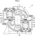
Fig. 3] Fig. 3 is a cross-sectional view taken along the line III-III and viewed in the direction of the arrows inFig. 2 . - [
Fig. 4] Fig. 4 is a perspective view illustrating a meshing state between a screw rotor and a gate rotor assembly. - [
Fig. 5] Fig. 5 is a plan view of a gate rotor assembly. - [
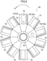
Fig. 6] Fig. 6 is a plan view illustrating a state in which a gate rotor is assembled to a first support member. - [
Fig. 7] Fig. 7 is a perspective view of a gate block. - [
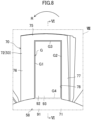
Fig. 8] Fig. 8 is an enlarged plan view of a gate block of a gate rotor assembly. - [
Fig. 9] Fig. 9 is a cross-sectional view taken along the line IX-IX and viewed in the direction of the arrows inFig. 8 . - [
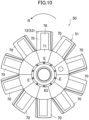
Fig. 10] Fig. 10 is a diagram according toModification 1 and corresponding toFig. 5 . - [
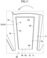
Fig. 11] Fig. 11 is a diagram according to Modification 2 and corresponding toFig. 8 . - [
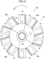
Fig. 12] Fig. 12 is a diagram according toModification 3 and corresponding toFig. 5 . - [
Fig. 13] Fig. 13 is a plan view of a gate rotor according toModification 4. - Hereinafter, an embodiment of the present disclosure will be described in detail with reference to the drawings. Note that the present disclosure is not limited to the embodiment described below and can be variously changed in a range not deviating from the technical idea of the present disclosure. Since the drawings are intended to conceptually describe the present disclosure, dimensions, ratios, or the number may be exaggerated or simplified, as necessary, for ease of understanding.
- As illustrated in
Fig. 1 , a screw compressor (10) is provided in a refrigeration apparatus (1). The refrigeration apparatus (1) includes a refrigerant circuit (1a) filled with a refrigerant. The refrigerant circuit (1a) includes the screw compressor (10), a radiator (3), a decompression mechanism (4), and an evaporator (5). The decompression mechanism (4) is an expansion valve. In the refrigerant circuit (1a), a vapor compression refrigeration cycle is performed. - In the refrigeration cycle, the refrigerant compressed by the screw compressor (10) dissipates heat into air at the radiator (3). The refrigerant that has dissipated heat is decompressed by the decompression mechanism (4) and evaporates at the evaporator (5). The evaporated refrigerant is sucked into the screw compressor (10).
- The refrigeration apparatus (1) is an air conditioning apparatus. The air conditioning apparatus may be an apparatus dedicated to cooling, an apparatus dedicated to heating, or an air conditioning apparatus in which cooling and heating are switched. In this case, the air conditioning apparatus includes a switching mechanism (for example, a four-way switching valve) that switches a circulation direction of the refrigerant. The refrigeration apparatus (1) may be a water heater, a chiller unit, a cooling apparatus that cools air in a chamber, or the like. The cooling apparatus cools air inside a refrigerating chamber, a freezing chamber, a container, or the like.
- The screw compressor (10) in the present embodiment compresses a sucked low-pressure gas refrigerant and discharges a high-pressure gas refrigerant. As illustrated in
Fig. 2 to Fig. 4 , the screw compressor (10) in the present embodiment is a single-screw compressor including one screw rotor (40). The screw compressor (10) in the present embodiment performs single-stage compression. - As illustrated in
Fig. 2 andFig. 3 , the screw compressor (10) includes a casing (11), an electric motor (17), a drive shaft (18), and a compression mechanism (19). The electric motor (17), the drive shaft (18), and the compression mechanism (19) are accommodated in the casing (11). The compression mechanism (19) includes one screw rotor (40) and two gate rotor assemblies (50). - As illustrated in
Fig. 2 , the casing (11) has a cylindrical shape whose two ends are closed. The casing (11) is disposed in an orientation in which the longitudinal direction thereof is substantially horizontal. The casing (11) includes a body portion (12) and a cylinder portion (16). The body portion (12) has a laterally elongated cylindrical shape whose two ends are closed. The cylinder portion (16) has a substantially cylindrical shape and is disposed in the vicinity of the center of the body portion (12) in the longitudinal direction. The cylinder portion (16) is formed to be integrated with the body portion (12). The inner peripheral surface of the cylinder portion (16) is a cylindrical surface. - A suction port (14) and a discharge port (15) are formed in the body portion (12). The suction port (14) is formed in an upper portion of one end portion (a left end portion in
Fig. 2 ) of the casing (11). The discharge port (15) is formed in an upper portion of another end portion (a right end portion inFig. 2 ) of the casing (11). - An internal space of the body portion (12) is partitioned into a low-pressure space (S1) and a high-pressure space (S2). The low-pressure space (S1) is formed closer than the cylinder portion (16) to one end of the body portion (12) and is in communication with the suction port (14). The high-pressure space (S2) is formed closer than the cylinder portion (16) to another end of the body portion (12) and is in communication with the discharge port (15).
- The electric motor (17) is disposed in the low-pressure space (S1). The drive shaft (18) couples the electric motor (17) to the screw rotor (40). The electric motor (17) rotationally drives the screw rotor (40).
- As illustrated in
Fig. 2 , the screw rotor (40) is rotatably accommodated in the cylinder portion (16). As illustrated inFig. 4 , the screw rotor (40) is a columnar member that is made of a metal. The outer peripheral surface of the screw rotor (40) is in sliding contact with the inner peripheral surface of the cylinder portion (16) via an oil film of a lubricating oil. The front side of the screw rotor (40) inFig. 4 is located on the side of the low-pressure space (S1), and the rear side of the screw rotor (40) inFig. 4 is located on the side of the high-pressure space (S2) . - A plurality (six in the present embodiment) of helical grooves (41) are formed on an outer peripheral portion of the screw rotor (40). Each of the helical grooves (41) is a groove helically extending in the circumferential direction and the axial direction of the screw rotor (40). The six helical grooves (41) are disposed at equal angular intervals in the circumferential direction of the screw rotor (40). In each of the helical grooves (41) of the screw rotor (40), an end on one end side (front end side in
Fig. 4 ) of the drive shaft (18) serves as a suction-side end (42), and an end on another end side (rear end side inFig. 4 ) of the drive shaft (18) serves as a discharge-side end (43). - An end portion of the screw rotor (40) on the suction side (the side of low-pressure space (S1)) has a tapered shape. In the screw rotor (40) illustrated in
Fig. 4 , the suction-side ends (42) of the helical grooves (41) are open at the end surface of the screw rotor (40) on the suction side while the discharge-side ends (43) of the helical grooves (41) are not open at the end surface of the screw rotor (40) on the discharge side. - As illustrated in
Fig. 3 , each of the gate rotor assemblies (50) is rotatably attached to the body portion (12) of the casing (11). Each of the gate rotor assemblies (50) includes one gate rotor (51), one first support member (56), and one second support member (58). In the gate rotor assembly (50), the first support member (56), the gate rotor (51), and the second support member (58) are stacked in this order. The gate rotor (51) is sandwiched and held between the first support member (56) and the second support member (58) . - The gate rotor (51) is a circular flat plate-shaped member that is made of a resin. As illustrated in
Fig. 4 , a plurality (ten in the present embodiment) of gates (53) are radially provided on the gate rotor (51). Each of the gates (53) is a substantially rectangular flat plate-shaped portion. In the present embodiment, the gate rotor (51) is constituted by a plurality of gate blocks (70) in which the gates (53) are formed separately from each other. Details of the structure of the gate rotor (51) will be described later. - Each of the gates (53) enters each helical groove (41) of the screw rotor (40) and form a compression chamber (32) by sliding on the wall surface of the helical groove (41). A front surface (61) of the gate rotor (51) is a surface on the side of the compression chamber (32). A back surface (62) of the gate rotor (51) is a surface opposite to the front surface (61).
- The first support member (56) is a member that is made of a metal. The first support member (56) is provided in contact with the back surface (62) of the gate rotor (51) and supports the gate rotor (51). The second support member (58) is a flat plate-shaped member that is made of a metal. The second support member (58) is provided in contact with the front surface (61) of the gate rotor (51) and supports the gate rotor (51). Details of the structures of the first support member (56) and the second support member (58) will be also described later.
- Gate rotor chambers (21) are formed one each on the left and right sides of the cylinder portion (16) illustrated in
Fig. 3 . The gate rotor assemblies (50) are accommodated one each in the gate rotor chambers (21). Each of the gate rotor chambers (21) is in communication with the low-pressure space (S1). - Specifically, each of the gate rotor chambers (21) is provided with a bearing housing (22). The bearing housing (22) is a cylindrical member that is made of a metal. The bearing housing (22) is fixed to the body portion (12) of the casing (11). Each of the gate rotor assemblies (50) is rotatably supported by the bearing housing (22) via a bearing.
- In
Fig. 3 , the front surface (61) of the gate rotor (51) of the gate rotor assembly (50) disposed on the right side of the screw rotor (40) faces upward. InFig. 3 , the front surface (61) of the gate rotor (51) of the gate rotor assembly (50) disposed on the left side of the screw rotor (40) faces downward. The two gate rotor assemblies (50) are disposed in orientations in which the gate rotor assemblies (50) are axially symmetric with respect to the axis of the screw rotor (40). The axis of each of the gate rotor assemblies (50) extends in a plane perpendicular to the axis of the screw rotor (40). - The gate rotor assemblies (50) are disposed to extend through the cylinder portion (16). The gate rotor assemblies (50) rotate with rotation of the screw rotor (40). Then, the rotation of the gate rotor assemblies (50) causes the gates (53) of the gate rotor (51) to enter the helical grooves (41) of the screw rotor (40) and mesh with the screw rotor (40) .
- As illustrated in
Fig. 2 andFig. 3 , the compression chamber (32) (hereinafter also referred to as the high-pressure chamber) is formed in the screw compressor (10) by the screw rotor (40), the gate rotor (51), and the cylinder portion (16) of the casing (11). The compression chamber (32) is a closed space surrounded by the wall surfaces of the helical grooves (41) of the screw rotor (40), the front surfaces (61) of the gates (53) of the gate rotor (51), and the inner peripheral surface of the cylinder portion (16). In the helical grooves (41), a space formed opposite to the compression chamber (32) with the gates (53) interposed therebetween serves as a low-pressure chamber. The low-pressure chamber is a space in which a pressure is lower than the pressure in the compression chamber (32). - Details of the configuration of each gate rotor assembly (50) will be described in detail with reference to
Fig. 3 to Fig. 9 . In the following description, the "axial direction" refers to the direction in which the axis of a first shaft portion (82) of the first support member (56) extends, the "radial direction" refers to the direction orthogonal to the axis of the first shaft portion (82), and the "circumferential direction" refers to the circumferential direction based on the axis of the first shaft portion (82). In the following description, the "front surface" refers to a surface on the side of the compression chamber (32), and the "back surface" refers to a surface on the side of the low-pressure chamber. - As illustrated in
Fig. 6 , the gate rotor (51) is constituted by a plurality (ten in the present embodiment) of the gate blocks (70) that extend radially. The gate blocks (70) include a first gate block (70a) including one gate (53) and a second gate block (70b) including one gate (53). Each of the gate blocks (70) is made of a resin. Each of the gate blocks (70) is manufactured by injection molding. Each of the gate blocks (70) may be machined after molded by injection molding. - Each of the gate blocks (70) in the present embodiment includes one base portion (71) and one gate portion (72).
- Each base portion (71) is a portion of the gate block (70) close to the axis of the gate rotor assembly (50). Each of the base portions (71) has a substantially trapezoidal shape so that side surfaces of the base portions (71) adjacent to each other are in surface contact with each other.
- The gate portion (72) is a portion extending toward the outer side in the radial direction from an outer peripheral portion of the base portion (71). The gate portion (72) constitutes the gate (53) of the gate rotor (51). The gate portion (72) has a substantially rectangular shape so as to mesh with each helical groove (41) of the screw rotor (40). In the gate portion (72) in the present embodiment, the width of the gate portion (72) is substantially constant from the inner side toward the outer side in the radial direction of the gate rotor (51).
- As illustrated in
Fig. 7 , the gate portion (72) is constituted by a bottom surface portion (74), a leading-end wall portion (75), a front side wall portion (76), and a rear side wall portion (77). The bottom surface portion (74) is a planar portion extending toward the outer side in the radial direction from the base portion (71). As illustrated inFig. 9 , the thickness of the bottom surface portion (74) is thinner than the thickness of the base portion (71). In other words, the bottom surface portion (74) is lowered by one step from the base portion (71). - The leading-end wall portion (75) is provided at a leading end portion of the bottom surface portion (74). The leading-end wall portion (75) protrudes from the bottom surface portion (74) toward the second support member (58) (upward in
Fig. 9 ). The front side wall portion (76) is provided at a side edge portion of the bottom surface portion (74) on the front side in a rotation direction R of the gate rotor (51). The front side wall portion (76) protrudes from the bottom surface portion (74) toward the second support member (58). The rear side wall portion (77) is provided at a side edge portion of the bottom surface portion (74) on the rear side in the rotation direction R of the gate rotor (51). The rear side wall portion (77) protrudes from the bottom surface portion (74) toward the second support member (58). - The gate portion (72) includes a concave portion (78). The concave portion (78) is a portion surrounded by the bottom surface portion (74), the leading-end wall portion (75), the front side wall portion (76), and the rear side wall portion (77) of the gate portion (72). A bottom portion of the concave portion (78) has a substantially rectangular shape. The concave portion (78) is recessed toward the first support member (56).
- As illustrated in
Fig. 3 andFig. 4 , the first support member (56) includes a disk portion (81), a first shaft portion (82), a second shaft portion (83), and a plurality of first gate support portions (84). - The disk portion (81) is a portion having a slightly thick disk shape. The first shaft portion (82) is a portion having a round rod shape. The first shaft portion (82) is provided on the back surface side of the disk portion (81). The first shaft portion (82) extends from a central portion of the disk portion (81). The axis of the first shaft portion (82) coincides with the axis of the disk portion (81) .
- The second shaft portion (83) is a portion having a columnar shape. The second shaft portion (83) is provided on the front surface side of the disk portion (81). The second shaft portion (83) extends from a central portion of the disk portion (81). The axis of the second shaft portion (83) coincides with the axis of the first shaft portion (82). The axis of the second shaft portion (83) coincides with the axis of the disk portion (81). The cross-sectional area of the second shaft portion (83) is smaller than the cross-sectional area of the first shaft portion (82). The gate rotor (51) and the second support member (58) are fitted to the second shaft portion (83). The gate blocks (70) of the gate rotor (51) are arranged to surround the second shaft portion (83).
- A groove (not illustrated) is formed, on the outer peripheral surface of the second shaft portion (83), at a position close to the compression chamber (32). Specifically, on the second shaft portion (83), the groove is formed at a position closer than the position where the second support member (58) is disposed to the compression chamber (32). The groove is formed over the entire circumference of the second shaft portion (83). A stopper ring (for example, a circlip) is fitted into the groove. With the stopper ring fitted into the groove, movement of each of the gate blocks (70) and the second support member (58) in the axial direction is restricted. In other words, the stopper ring restricts movement of the second support member (58) in the axial direction, thereby restricting movement of each of the gate blocks (70), which are sandwiched between the first support member (56) and the second support member (58), in the axial direction.
- The first support member (56) includes the same number (ten in the present embodiment) of the first gate support portions (84) as the number of the gates (53) of the gate rotor (51). The first gate support portions (84) are portions extending radially toward the outer side in the radial direction from an outer peripheral portion of the disk portion (81). Each of the first gate support portions (84) extends along the back surface of a corresponding one of the gate portions (72).
- As illustrated in
Fig. 9 , each of the first gate support portions (84) covers substantially the entirety of the back surface of the corresponding gate portion (72). Each of the first gate support portions (84) supports, in a state of being in contact with the back surface of the corresponding gate portion (72), the corresponding gate portion (72) from the back surface side. Each of the first gate support portions (84) is formed to have a substantially triangular cross-section perpendicular to an extending direction thereof. - Since each first gate support portion (84) supports the gate portion (72) corresponding to the first gate support portion (84) from the back surface side, it is possible to ensure strength against a pressure that acts due to compression of the refrigerant in the compression chamber (32) during operation of the screw compressor (10) and that is in a direction from the front surface (61) toward the back surface (62) of the gate rotor (51).
- As illustrated in
Fig. 4 andFig. 5 , the second support member (58) includes an annular portion (91) and a plurality of second gate support portions (92). - The annular portion (91) is a portion having an annular shape. The second shaft portion (83) of the first support member (56) is inserted into a hole formed at the center of the annular portion (91). The second support member (58) includes the same number (ten in the present embodiment) of the second gate support portions (92) as the number of the gates (53) of the gate rotor (51). The second gate support portions (92) are each a portion extending radially toward the outer side in the radial direction from an outer peripheral portion of the annular portion (91). Each of the second gate support portions (92) extends along the front surface of a corresponding one of the gate portions (72). Each of the second gate support portions (92) supports, in a state of being in contact with the front surface of the corresponding gate portion (72), the corresponding gate portion (72) from the front surface side.
- Since each second gate support portion (92) supports the gate portion (72) corresponding to the second gate support portion (92) from the front surface side, it is possible to increase strength against a pressure that is generated during operation of the screw compressor (10) in a rare case from the side of the back surface (62) of the gate rotor (51). Consequently, it is possible to reduce damage to the gate rotor (51) caused by a pressure applied in a direction from the back surface (62) toward the front surface (61) of the gate rotor (51), that is, in a direction opposite to a normal direction.
- As illustrated in
Fig. 9 , the second gate support portions (92) each include a protruding portion (93). The protruding portion (93) is a portion protruding toward the gate portion (72). In other words, the thickness of each second gate support portion (92) is larger than the thickness of the annular portion (91). As illustrated inFig. 8 , the protruding portion (93) has a substantially rectangular shape. The protruding portion (93) engages with the concave portion (78) of the gate portion (72). The protruding portion (93) is in surface contact with a bottom portion of the concave portion (78). The area of the protruding portion (93) is smaller than the area of the bottom portion of the concave portion (78). - Since the protruding portion (93) engages with the concave portion (78) of the gate portion (72) as described above, it is possible to restrict large movement of the gate block (70) in the circumferential direction and the radial direction.
- As illustrated in
Fig. 8 , a slight gap (G) is formed between the inner peripheral surface of the concave portion (78) and the outer peripheral surface of the protruding portion (93) so as to surround the entire circumference of the protruding portion (93). Specifically, the gap (G) is constituted by a first gap (G1), a second gap (G2), a third gap (G3), and a fourth gap (G4). - The first gap (G1) is formed between the inner side surface of the front side wall portion (76) and the front side surface of the protruding portion (93). The second gap (G2) is formed between the inner side surface of the rear side wall portion (77) and the rear side surface of the protruding portion (93). The third gap (G3) is formed between the inner side surface of the leading-end wall portion (75) and the leading-end side surface of the protruding portion (93). The fourth gap (G4) is formed between the leading end surface of the base portion (71) and the base-end side surface of the protruding portion (93).
- Here, during operation of the screw compressor (10), components constituting the screw compressor (10) thermally expand due to compression heat generated with compression of a refrigerant. In this case, the positions of the bearing housings (22) supporting the gate rotor assemblies (50) change with thermal expansion of the body portion (12) of the casing (11). With changes in the positions of the bearing housings (22), the position of the gate rotor (51) also changes. Consequently, the relative positions of the screw rotor (40) and the gate rotor (51) are shifted. When the relative positions of the screw rotor (40) and the gate rotor (51) are shifted, the gate rotor (51) made of a resin is excessively pressed against the screw rotor (40) and is thereby worn. Wear of the gate rotor (51) causes a refrigerant to leak from the compression chamber (32) and thereby causes deterioration of the performance of the screw compressor (10).
- In contrast, in each gate rotor assembly (50) in the present embodiment, the axial movement of the gate rotor (51) is restricted since the gate rotor (51) is in contact with and sandwiched between the first support member (56) and the second support member (58). Meanwhile, since the gap (G) is formed between the inner peripheral surface of the concave portion (78) of the gate portion (72) of each of the gate blocks (70) and the outer peripheral surface of the protruding portion (93) of the second support member (58) so as to surround the entire circumference of the protruding portion (93), each of the gate blocks (70) is configured to be movable slightly in the circumferential direction and the radial direction on the front surface of the first support member (56). In other words, the gap (G) allows positional displacement of the gate rotor (51) caused by thermal expansion. Consequently, even when a change in the relative position of the gate rotor (51) with respect to the screw rotor (40) is generated by thermal expansion, the gate rotor (51) and the screw rotor (40) can mesh with each other normally since the position of the gate rotor (51) changes by following the screw rotor (40) due to the gap (G). As a result, wear of the gate rotor (51) can be suppressed.
- In the screw compressor (10), the screw rotor (40) is driven by the electric motor (17). When the screw rotor (40) rotates, the gate rotor assemblies (50) meshing with the screw rotor (40) rotate. When the gate rotor assemblies (50) rotate, the gates (53) of the gate rotors (51) enter the helical grooves (41) of the screw rotor (40) and relatively move from the suction-side end (42) toward the discharge-side end (43) of the helical grooves (41) that the gates (53) have entered. As a result, the capacity of the compression chamber (32) is gradually reduced, and the refrigerant in the compression chamber (32) is compressed.
- A low-pressure gas refrigerant that has flowed out from the evaporator (5) is sucked into the screw compressor (10) through the suction port (14). The gas refrigerant that has flowed into the low-pressure space (S1) through the suction port (14) flows into the compression chamber (32) and is compressed. The compressed gas refrigerant is discharged into the high-pressure space (S2). The refrigerant that has flowed into the high-pressure space (S2) is discharged to the outside of the screw compressor (10) through the discharge port (15). The high-pressure gas refrigerant discharged through the discharge port (15) flows toward the radiator (3).
- (4-1)
The gate rotor assemblies (50) each include the gate rotor (51) made of a resin and in which a plurality of the flat plate-shaped gates (53) that mesh with the helical grooves (41) of the screw rotor (40) are radially formed; the first support member (56) made of a metal and including a plurality of the first gate support portions (84) that each support a corresponding one of the gates (53) from the back surface side of the corresponding gate (53), the first support member (56) supporting the gate rotor (51) such that the gate rotor (51) is rotatable; and the second support member (58) made of a metal and including a plurality of the second gate support portions (92) that each support a corresponding one of the gates (53) from the front surface side of the corresponding gate (53). - Since each of the gate rotor assemblies (50) includes the second support member (58) made of a metal and including the second gate support portions (92) that each support a corresponding one of the gates (53) from the front surface side, it is possible to reinforce the gates (53) against a pressure that acts in a direction from the back surface toward the front surface of the gates (53) during operation of the screw compressor (10). Consequently, it is possible to increase strength against a pressure generated in a direction opposite to a normal direction during operation of the screw compressor (10).
- (4-2)
The gate rotor (51) is sandwiched between the first support member (56) and the second support member (58). Each of the second gate support portions (92) of the second support member (58) includes the protruding portion (93) protruding toward a corresponding one of the gates (53). In each of the plurality of gates (53), the concave portion (78) with which the protruding portion (93) of a corresponding one of the second gate support portions (92) engages is formed. The gap (G) is formed between the inner peripheral surface of the concave portion (78) and the outer peripheral surface of the protruding portion (93) so as to surround the entire circumference of the protruding portion (93) . - Movement of the gate rotor (51) in the axis direction is restricted since the gate rotor (51) is sandwiched between the first support member (56) and the second support member (58). Meanwhile, since the gap (G) is formed between the inner peripheral surface of the concave portion (78) of each gate (53) and the outer peripheral surface of the protruding portion (93) of each of the second gate support portions (92) so as to surround the entire circumference of the protruding portion (93), the gate rotor (51) is movable in the radial direction and the circumferential direction.
- Therefore, even when changes in the relative positions of the screw rotor (40) and the gate rotor assemblies (50) are generated by thermal expansion of the screw compressor (10), the gate rotor (51) and the screw rotor (40) can normally mesh with each other since the position of the gate rotor (51) changes by following the screw rotor (40) due to the gap (G). Consequently, it is possible to suppress wear of the gate rotor (51) caused by thermal expansion.
- (4-3)
The gate rotor (51) includes a plurality of the gate blocks (70) each including one gate (53). Since the gate rotor (51) is divided into a plurality of gate blocks (70) as described above, it is possible to easily move each of the gate blocks (70) in accordance with the degree of thermal expansion. - With the gate rotor (51) divided into a plurality of the gate blocks (70), it is possible to manufacture each of the gate blocks (70) by injection molding and thus possible to reduce manufacturing costs.
- (4-4)
The gate rotor (51) is made of a resin. Consequently, seizing of a sliding portion in meshing with the screw rotor (40) can be suppressed. - (4-5)
The gate rotor (51) is sandwiched between the first support member (56) and the second support member (58). The gates (53) are each held by the first support member (56) and the second support member (58) such that the gates (53) are movable slightly in the radial direction and the circumferential direction of the first support member (56). - Here, when a component of the screw compressor (10) thermally expands due to operation of the screw compressor (10), the relative positions of the screw rotor (40) and the gate rotor assembly (50) change. At this time, the gate rotor (51) is worn by being pressed against the screw rotor (40) with an excessive force.
- Movement of the gate rotor (51) in the axis direction is restricted since the gate rotor (51) is sandwiched between the first support member (56) and the second support member (58). Meanwhile, the gate rotor (51) is movable in the radial direction and the circumferential direction since the gates (53) are each held by the first support member (56) and the second support member (58) such that the gates (53) are movable slightly in the radial direction and the circumferential direction of the first support member (56).
- Therefore, even when changes in the relative positions of the screw rotor (40) and each gate rotor assembly (50) are generated by thermal expansion of the screw compressor (10), the gate rotor (51) and the screw rotor (40) can normally mesh with each other since the gates (53) slightly move in the radial direction and the circumferential direction and thereby cause the position of the gate rotor (51) to change by following the screw rotor (40). Consequently, it is possible to suppress wear of the gate rotor (51) caused by thermal expansion of a component.
- The aforementioned embodiment may be modified into modifications described below. In the following description, differences from the aforementioned embodiment will be described basically.
- The gate rotor assembly (50) in the aforementioned embodiment may include an elastic body (E) that presses each of the gate blocks (70) against the screw rotor (40). Specifically, as illustrated in
Fig. 10 , the elastic body (E) is disposed between a base end portion of the base portion (71) of each of the gate blocks (70) and the second shaft portion (83) of the first support member (56). In the present modification, the elastic body (E) is a coil spring. The coil spring (E) presses each gate block (70) toward the outer side in the radial direction. The elastic body (E) may be made of a rubber material. - Each of the gate blocks (70) in the aforementioned embodiment is configured to be slightly movable in the circumferential direction and the radial direction on the front surface of the first support member (56). Therefore, when a centrifugal force generated by rotation of the screw compressor (10) does not sufficiently act on each of the gate blocks (70), a gap is formed between the leading end surface of each of the gate blocks (70) and the helical grooves (41) of the screw rotor (40).
- Thus, in the present modification, the gate rotor assembly (50) includes the elastic body (E) that presses each of the gate blocks (70) against the screw rotor (40), thereby making it possible to suppress formation of a gap between the leading end surface of each gate block (70) and the helical grooves (41) of the screw rotor (40).
- As illustrated in
Fig. 11 , the width of the gate portion (72) of each of the gate blocks (70) in the aforementioned embodiment may increase from the inner side toward the outer side in the radial direction of the gate rotor (51). In other words, the gate portion (72) may have a fan shape. - As described in
Modification 1, a gap is formed between the leading end surface of each of the gate blocks (70) and the helical grooves (41) of the screw rotor (40) in the aforementioned embodiment when the centrifugal force acting on each of the gate blocks (70) is insufficient. Thus, in the present modification, the gate portion (72) has a fan shape to suppress coming-off of the gate blocks (70) from the helical grooves (41) when the gate rotor (51) meshes with the helical grooves (41) of the screw rotor (40). - The gate blocks (70) in the aforementioned embodiment may each include a plurality of the gate portions (72). Specifically, for example, as illustrated in
Fig. 12 , the gate rotor (51) includes the first gate block (70a) that includes one base portion (71) and two gate portions (72), and the second gate block (70b) that includes one base portion (71) and three gate portions (72). As in the aforementioned embodiment, it is also possible in the present modification to obtain an effect that each of the gate blocks (70) is easily moved in accordance with the degree of thermal expansion. - As illustrated in
Fig. 13 , the gate rotor (51) in the aforementioned embodiment may be formed integrally without being divided into a plurality of the gate blocks (70). It is also possible in the present modification to suppress wear of the gate rotor (51) caused by thermal expansion since the gap (G) is formed between the concave portion (78) of the gate portion (72) and the protruding portions (93) of the second gate support portions (92). InFig. 13 , an example in which the gate rotor (51) is provided with eleven gates (53) is illustrated. - The gate rotor (51) in the aforementioned embodiment may be provided in a screw compressor that performs two-stage compression. In the screw compressor that performs two-stage compression, for example, a compression chamber (32) on the lower side of the screw rotor (40) serves as a first compression chamber, and a compression chamber (32) on the upper side of the screw rotor (40) serves as a second compression chamber. A refrigerant that has flowed into the low-pressure space (S1) through the suction port (14) flows into the first compression chamber and is compressed. The refrigerant that has been compressed in the first compression chamber and discharged flows into the second compression chamber through a passage formed inside the casing (11). The refrigerant that has flowed into the second compression chamber is compressed and then discharged into the high-pressure space (S2).
- The gate rotor (51), which is made of a resin in the aforementioned embodiment, may be made of a material other than resins. For example, the gate rotor (51) may be made of a metal.
- The gap (G) of the gate rotor assembly (50) in the aforementioned embodiment may be formed between a concave portion formed on the second gate support portion (92) and a protruding portion formed on the gate portion (72). In other words, in the present modification, the concave portion may be formed on the member on which the protruding portion in the aforementioned embodiment is formed while the protruding portion is formed on the member on which the concave portion in the aforementioned embodiment is formed.
- As in the aforementioned embodiment, it is also possible in the present modification for the gate rotor (51) to move in the radial direction and the circumferential direction since the gap (G) is formed between the inner peripheral surface of the concave portion of each of the second gate support portions (92) and the outer peripheral surface of the protruding portion of the gate portion (72) so as to surround the entire circumference of the protruding portion.
- Therefore, even when changes in the relative positions of the screw rotor (40) and the gate rotor assemblies (50) are generated by thermal expansion of the screw compressor (10), the gate rotor (51) and the screw rotor (40) can normally mesh with each other since the position of the gate rotor (51) changes by following the screw rotor (40) due to the gap (G). Consequently, it is possible to suppress wear of the gate rotor (51) caused by thermal expansion of a component.
- While an embodiment and modifications have been described above, it should be understood that various changes in forms and details are available without deviating from the gist and the scope of the claims. In addition, elements in the embodiment and modifications described above and other embodiments may be combined, as appropriate, or replaced.
- The terms such as "first", "second", "third"... are used for distinction between words to which these terms are given, and the terms are not intended to limit the number or order of the words.
- As described above, the present disclosure is useful for a screw compressor and a refrigeration apparatus.
-
- 1 refrigeration apparatus
- 10 screw compressor
- 11 casing
- 40 screw rotor
- 41 helical groove
- 50 gate rotor assembly
- 51 gate rotor
- 53 gate
- 56 first support member
- 58 second support member
- 70A first gate block
- 70B second gate block
- 78 concave portion
- 84 first gate support portion
- 92 second gate support portion
- 93 protruding portion
- E coil spring (elastic body)
- G gap
Claims (7)
- A screw compressor comprisinga casing (11);a screw rotor (40) accommodated in the casing (11) and configured to be rotationally driven; anda gate rotor assembly (50) configured to rotate with rotation of the screw rotor (40), whereinthe gate rotor assembly (50) includesa gate rotor (51) including a plurality of flat plate-shaped gates (53) each configured to mesh with a helical groove (41) of the screw rotor (40),a first support member (56) made of a metal and including a plurality of first gate support portions (84) each configured to support a corresponding one of the gates (53) from a back surface side of the corresponding one of the gates (53), the first support member (56) being configured to support the gate rotor (51) such that the gate rotor (51) is rotatable, anda second support member (58) made of a metal and including a plurality of second gate support portions (92) each configured to support a corresponding one of the gates (53) from a front surface side of the corresponding one of the gates (53).
- The screw compressor according to claim 1, whereinthe gate rotor (51) is sandwiched between the first support member (56) and the second support member (58), andthe gates (53) are each held by the first support member (56) and the second support member (58) such that the gates (53) are movable slightly in a radial direction and a circumferential direction of the first support member (56).
- The screw compressor according to claim 2, whereineach of the second gate support portions (92) of the second support member (58) includes a protruding portion (93) protruding toward a corresponding one of the gates (53),a concave portion (78) with which the protruding portion (93) of a corresponding one of the second gate support portions (92) engages is formed on each of the plurality of gates (53), anda gap (G) is formed between an inner peripheral surface of the concave portion (78) and an outer peripheral surface of the protruding portion (93) so as to surround an entire circumference of the protruding portion (93).
- The screw compressor according to claim 2 or claim 3, wherein
the gate rotor (51) includes a first gate block (70a) including one or a plurality of the gates (53) and a second gate block (70b) including one or a plurality of the gates (53) . - The screw compressor according to claim 4, wherein
the gate rotor assembly (50) further includes an elastic body (E) configured to press each of the first gate block (70a) and the second gate block (70b) against the screw rotor (40). - The screw compressor according to claim 4, wherein
the gates (53) of the first gate block (70a) and the gates (53) of the second gate block (70b) each have a width that increases from an inner side toward an outer side in a radial direction of the gate rotor (51). - A refrigeration apparatus comprising the screw compressor according to any one of claims 1 to 6.
Applications Claiming Priority (2)
| Application Number | Priority Date | Filing Date | Title |
|---|---|---|---|
| JP2022051658 | 2022-03-28 | ||
| PCT/JP2023/011543 WO2023190048A1 (en) | 2022-03-28 | 2023-03-23 | Screw compressor and freezer |
Publications (3)
| Publication Number | Publication Date |
|---|---|
| EP4477887A1 true EP4477887A1 (en) | 2024-12-18 |
| EP4477887A4 EP4477887A4 (en) | 2025-06-04 |
| EP4477887B1 EP4477887B1 (en) | 2026-04-08 |
Family
ID=88202170
Family Applications (1)
| Application Number | Title | Priority Date | Filing Date |
|---|---|---|---|
| EP23780059.4A Active EP4477887B1 (en) | 2022-03-28 | 2023-03-23 | Screw compressor and freezer |
Country Status (5)
| Country | Link |
|---|---|
| US (1) | US12435719B2 (en) |
| EP (1) | EP4477887B1 (en) |
| JP (1) | JP7481660B2 (en) |
| CN (1) | CN118922626B (en) |
| WO (1) | WO2023190048A1 (en) |
Family Cites Families (15)
| Publication number | Priority date | Publication date | Assignee | Title |
|---|---|---|---|---|
| JPS5653102Y2 (en) * | 1973-10-06 | 1981-12-10 | ||
| JPS5318566Y2 (en) * | 1973-10-26 | 1978-05-18 | ||
| JPS526884Y2 (en) * | 1973-11-07 | 1977-02-14 | ||
| US4227867A (en) * | 1978-03-06 | 1980-10-14 | Chicago Pneumatic Tool Company | Globoid-worm compressor with single piece housing |
| JP3840899B2 (en) * | 2001-01-05 | 2006-11-01 | ダイキン工業株式会社 | Single screw compressor |
| US7153112B2 (en) * | 2003-12-09 | 2006-12-26 | Dresser-Rand Company | Compressor and a method for compressing fluid |
| JP2009174520A (en) | 2007-12-26 | 2009-08-06 | Daikin Ind Ltd | Gate rotor and screw compressor |
| JP4518206B2 (en) * | 2007-12-28 | 2010-08-04 | ダイキン工業株式会社 | Single screw compressor |
| JP2010127109A (en) * | 2008-11-25 | 2010-06-10 | Daikin Ind Ltd | Screw compressor and its manufacturing method |
| JP2010196582A (en) * | 2009-02-25 | 2010-09-09 | Daikin Ind Ltd | Single screw compressor |
| CN205605427U (en) * | 2016-03-02 | 2016-09-28 | 邵用葆 | Water spray list screw rod oil -free air compressor with fluid movement pressure and temperature balance |
| JP6729425B2 (en) * | 2017-01-30 | 2020-07-22 | ダイキン工業株式会社 | Single screw compressor |
| JP2019007399A (en) | 2017-06-23 | 2019-01-17 | ダイキン工業株式会社 | Single screw compressor |
| CN107893765A (en) * | 2017-11-07 | 2018-04-10 | 西安交大思源科技股份有限公司 | A kind of single screw rod water-lubricated compressor |
| GB2581204B (en) * | 2019-02-11 | 2022-07-20 | J & E Hall Ltd | Screw compressor |
-
2023
- 2023-03-23 CN CN202380029531.0A patent/CN118922626B/en active Active
- 2023-03-23 EP EP23780059.4A patent/EP4477887B1/en active Active
- 2023-03-23 JP JP2023046485A patent/JP7481660B2/en active Active
- 2023-03-23 WO PCT/JP2023/011543 patent/WO2023190048A1/en not_active Ceased
-
2024
- 2024-09-23 US US18/893,655 patent/US12435719B2/en active Active
Also Published As
| Publication number | Publication date |
|---|---|
| CN118922626A (en) | 2024-11-08 |
| EP4477887A4 (en) | 2025-06-04 |
| CN118922626B (en) | 2025-10-24 |
| US20250012280A1 (en) | 2025-01-09 |
| WO2023190048A1 (en) | 2023-10-05 |
| US12435719B2 (en) | 2025-10-07 |
| JP2023145387A (en) | 2023-10-11 |
| JP7481660B2 (en) | 2024-05-13 |
| EP4477887B1 (en) | 2026-04-08 |
Similar Documents
| Publication | Publication Date | Title |
|---|---|---|
| CN110360101B (en) | Compressor with bushing | |
| US11732710B2 (en) | Screw compressor, and refrigeration device | |
| CN110469504B (en) | Compressor with bushing | |
| US8523548B2 (en) | Screw compressor having a gate rotor assembly with pressure introduction channels | |
| CN110418892A (en) | Rotary compressor | |
| KR20070083469A (en) | Screw compressor seal | |
| CN1823226B (en) | scroll compressor | |
| EP1851437B1 (en) | Capacity varying type rotary compressor | |
| EP4477887B1 (en) | Screw compressor and freezer | |
| US8568119B2 (en) | Single screw compressor | |
| US11428223B2 (en) | Rotary compressor with wear avoiding portion | |
| JP6729425B2 (en) | Single screw compressor | |
| EP3683445B1 (en) | Screw compressor | |
| TWI660122B (en) | Single-screw compressor and refrigeration cycle device including the same | |
| US20250012278A1 (en) | Screw compressor and freezer | |
| JP7372581B2 (en) | Screw compressor and refrigeration equipment | |
| CN111868384B (en) | Multistage compressor | |
| KR20180028302A (en) | Swash plate type compressure | |
| CN113883052A (en) | Compression mechanism and scroll compressor including the same | |
| WO2021240605A1 (en) | Two-stage single-screw compressor, and refrigeration and air-conditioning device | |
| JPH02259293A (en) | Compressor |
Legal Events
| Date | Code | Title | Description |
|---|---|---|---|
| STAA | Information on the status of an ep patent application or granted ep patent |
Free format text: STATUS: THE INTERNATIONAL PUBLICATION HAS BEEN MADE |
|
| PUAI | Public reference made under article 153(3) epc to a published international application that has entered the european phase |
Free format text: ORIGINAL CODE: 0009012 |
|
| STAA | Information on the status of an ep patent application or granted ep patent |
Free format text: STATUS: REQUEST FOR EXAMINATION WAS MADE |
|
| 17P | Request for examination filed |
Effective date: 20240913 |
|
| AK | Designated contracting states |
Kind code of ref document: A1 Designated state(s): AL AT BE BG CH CY CZ DE DK EE ES FI FR GB GR HR HU IE IS IT LI LT LU LV MC ME MK MT NL NO PL PT RO RS SE SI SK SM TR |
|
| P01 | Opt-out of the competence of the unified patent court (upc) registered |
Free format text: CASE NUMBER: APP_954/2025 Effective date: 20250108 |
|
| A4 | Supplementary search report drawn up and despatched |
Effective date: 20250507 |
|
| RIC1 | Information provided on ipc code assigned before grant |
Ipc: F04C 18/08 20060101ALI20250429BHEP Ipc: F01C 21/08 20060101ALI20250429BHEP Ipc: F04C 29/00 20060101ALI20250429BHEP Ipc: F04C 18/52 20060101AFI20250429BHEP |
|
| DAV | Request for validation of the european patent (deleted) | ||
| DAX | Request for extension of the european patent (deleted) | ||
| GRAP | Despatch of communication of intention to grant a patent |
Free format text: ORIGINAL CODE: EPIDOSNIGR1 |
|
| STAA | Information on the status of an ep patent application or granted ep patent |
Free format text: STATUS: GRANT OF PATENT IS INTENDED |
|
| INTG | Intention to grant announced |
Effective date: 20251201 |
|
| GRAS | Grant fee paid |
Free format text: ORIGINAL CODE: EPIDOSNIGR3 |
|
| GRAA | (expected) grant |
Free format text: ORIGINAL CODE: 0009210 |
|
| STAA | Information on the status of an ep patent application or granted ep patent |
Free format text: STATUS: THE PATENT HAS BEEN GRANTED |
|
| AK | Designated contracting states |
Kind code of ref document: B1 Designated state(s): AL AT BE BG CH CY CZ DE DK EE ES FI FR GB GR HR HU IE IS IT LI LT LU LV MC ME MK MT NL NO PL PT RO RS SE SI SK SM TR |
|
| REG | Reference to a national code |
Ref country code: CH Ref legal event code: F10 Free format text: ST27 STATUS EVENT CODE: U-0-0-F10-F00 (AS PROVIDED BY THE NATIONAL OFFICE) Effective date: 20260408 Ref country code: GB Ref legal event code: FG4D |
|
| REG | Reference to a national code |
Ref country code: DE Ref legal event code: R096 Ref document number: 602023015062 Country of ref document: DE |
|
| REG | Reference to a national code |
Ref country code: IE Ref legal event code: FG4D |