EP4477886A1 - Screw compressor and refrigeration device - Google Patents
Screw compressor and refrigeration device Download PDFInfo
- Publication number
- EP4477886A1 EP4477886A1 EP23779018.3A EP23779018A EP4477886A1 EP 4477886 A1 EP4477886 A1 EP 4477886A1 EP 23779018 A EP23779018 A EP 23779018A EP 4477886 A1 EP4477886 A1 EP 4477886A1
- Authority
- EP
- European Patent Office
- Prior art keywords
- gates
- helical grooves
- rotor
- seal
- screw rotor
- Prior art date
- Legal status (The legal status is an assumption and is not a legal conclusion. Google has not performed a legal analysis and makes no representation as to the accuracy of the status listed.)
- Granted
Links
Images





Classifications
-
- F—MECHANICAL ENGINEERING; LIGHTING; HEATING; WEAPONS; BLASTING
- F04—POSITIVE - DISPLACEMENT MACHINES FOR LIQUIDS; PUMPS FOR LIQUIDS OR ELASTIC FLUIDS
- F04C—ROTARY-PISTON, OR OSCILLATING-PISTON, POSITIVE-DISPLACEMENT MACHINES FOR LIQUIDS; ROTARY-PISTON, OR OSCILLATING-PISTON, POSITIVE-DISPLACEMENT PUMPS
- F04C18/00—Rotary-piston pumps specially adapted for elastic fluids
- F04C18/08—Rotary-piston pumps specially adapted for elastic fluids of intermeshing-engagement type, i.e. with engagement of co-operating members similar to that of toothed gearing
- F04C18/12—Rotary-piston pumps specially adapted for elastic fluids of intermeshing-engagement type, i.e. with engagement of co-operating members similar to that of toothed gearing of other than internal-axis type
- F04C18/14—Rotary-piston pumps specially adapted for elastic fluids of intermeshing-engagement type, i.e. with engagement of co-operating members similar to that of toothed gearing of other than internal-axis type with toothed rotary pistons
- F04C18/16—Rotary-piston pumps specially adapted for elastic fluids of intermeshing-engagement type, i.e. with engagement of co-operating members similar to that of toothed gearing of other than internal-axis type with toothed rotary pistons with helical teeth, e.g. chevron-shaped, screw type
-
- F—MECHANICAL ENGINEERING; LIGHTING; HEATING; WEAPONS; BLASTING
- F04—POSITIVE - DISPLACEMENT MACHINES FOR LIQUIDS; PUMPS FOR LIQUIDS OR ELASTIC FLUIDS
- F04C—ROTARY-PISTON, OR OSCILLATING-PISTON, POSITIVE-DISPLACEMENT MACHINES FOR LIQUIDS; ROTARY-PISTON, OR OSCILLATING-PISTON, POSITIVE-DISPLACEMENT PUMPS
- F04C18/00—Rotary-piston pumps specially adapted for elastic fluids
- F04C18/48—Rotary-piston pumps with non-parallel axes of movement of co-operating members
- F04C18/50—Rotary-piston pumps with non-parallel axes of movement of co-operating members the axes being arranged at an angle of 90 degrees
- F04C18/52—Rotary-piston pumps with non-parallel axes of movement of co-operating members the axes being arranged at an angle of 90 degrees of intermeshing engagement type, i.e. with engagement of co-operating members similar to that of toothed gearing
-
- F—MECHANICAL ENGINEERING; LIGHTING; HEATING; WEAPONS; BLASTING
- F04—POSITIVE - DISPLACEMENT MACHINES FOR LIQUIDS; PUMPS FOR LIQUIDS OR ELASTIC FLUIDS
- F04C—ROTARY-PISTON, OR OSCILLATING-PISTON, POSITIVE-DISPLACEMENT MACHINES FOR LIQUIDS; ROTARY-PISTON, OR OSCILLATING-PISTON, POSITIVE-DISPLACEMENT PUMPS
- F04C18/00—Rotary-piston pumps specially adapted for elastic fluids
- F04C18/08—Rotary-piston pumps specially adapted for elastic fluids of intermeshing-engagement type, i.e. with engagement of co-operating members similar to that of toothed gearing
- F04C18/082—Details specially related to intermeshing engagement type pumps
- F04C18/084—Toothed wheels
-
- F—MECHANICAL ENGINEERING; LIGHTING; HEATING; WEAPONS; BLASTING
- F25—REFRIGERATION OR COOLING; COMBINED HEATING AND REFRIGERATION SYSTEMS; HEAT PUMP SYSTEMS; MANUFACTURE OR STORAGE OF ICE; LIQUEFACTION SOLIDIFICATION OF GASES
- F25B—REFRIGERATION MACHINES, PLANTS OR SYSTEMS; COMBINED HEATING AND REFRIGERATION SYSTEMS; HEAT PUMP SYSTEMS
- F25B31/00—Compressor arrangements
- F25B31/02—Compressor arrangements of motor-compressor units
- F25B31/026—Compressor arrangements of motor-compressor units with compressor of rotary type
-
- F—MECHANICAL ENGINEERING; LIGHTING; HEATING; WEAPONS; BLASTING
- F04—POSITIVE - DISPLACEMENT MACHINES FOR LIQUIDS; PUMPS FOR LIQUIDS OR ELASTIC FLUIDS
- F04C—ROTARY-PISTON, OR OSCILLATING-PISTON, POSITIVE-DISPLACEMENT MACHINES FOR LIQUIDS; ROTARY-PISTON, OR OSCILLATING-PISTON, POSITIVE-DISPLACEMENT PUMPS
- F04C2230/00—Manufacture
- F04C2230/10—Manufacture by removing material
-
- F—MECHANICAL ENGINEERING; LIGHTING; HEATING; WEAPONS; BLASTING
- F04—POSITIVE - DISPLACEMENT MACHINES FOR LIQUIDS; PUMPS FOR LIQUIDS OR ELASTIC FLUIDS
- F04C—ROTARY-PISTON, OR OSCILLATING-PISTON, POSITIVE-DISPLACEMENT MACHINES FOR LIQUIDS; ROTARY-PISTON, OR OSCILLATING-PISTON, POSITIVE-DISPLACEMENT PUMPS
- F04C2250/00—Geometry
- F04C2250/20—Geometry of the rotor
Definitions
- the present disclosure relates to a screw compressor and a refrigeration apparatus.
- PTL 1 describes that a screw rotor for a screw compressor is manufactured by using a 5-axis machining center.
- a 5-axis machining center a workpiece is cut while a cutting tool, such as an end mill, attached to a spindle and the workpiece attached to a holder are both moved.
- the relative angle of a cutting tool with respect to the center axis of a screw rotor may become large.
- a spindle of a 5-axis machining center and a rotary table of the 5-axis machining center will interfere with each other.
- An object of the present disclosure is to refine the shapes of gates so as to avoid interference between a spindle and a rotary table when machining helical grooves that correspond to the gates by using a 5-axis machining center.
- a first aspect of the present disclosure is a screw compressor including a screw rotor (30) having a plurality of helical grooves (40) and a gate rotor (51) including gates (52) configured to mesh with the helical grooves (40) of the screw rotor (30).
- Each of the gates (52) has a first seal line (55) and a second seal line (56) each configured to come into contact with side wall surfaces (41) of the helical grooves (40) of the screw rotor (30).
- a shape of the first seal line (55) and a shape of the second seal line (56) are asymmetric with respect to a first imaginary straight line (L1) passing through a rotation center (O) of the gate rotor (51) and a first intermediate position (A) located on a tip end side of each of the gates (52) between the first seal line (55) and the second seal line (56).
- Each of the helical grooves (40) has a shape corresponding to each of the gates (52).
- each of the gates (52) by refining the shape of each of the gates (52), interference between a spindle and a rotary table can be avoided when machining the helical grooves (40), each of which corresponds to each of the gates (52), by using a 5-axis machining center.
- a second aspect of the present disclosure is the screw compressor according to the first aspect in which a second imaginary straight line (L2) passing through a rotation center (O) of the gate rotor (51) and a second intermediate position (B) located on a base end side of each of the gates (52) between the first seal line (55) and the second seal line (56) is inclined at a predetermined angle with respect to the first imaginary straight line (L1).
- a third aspect of the present disclosure is the screw compressor according to the first or second aspect in which, when viewed in an axial direction of the gate rotor (51), a maximum angle formed by a center axis (33) of the screw rotor (30) and a surface included in the side wall surfaces (41) of the helical grooves (40), the surface being configured to come into contact with the first seal line (55), is 145 degrees or less.
- the interference between the spindle and the rotary table can be avoided when machining the helical grooves (40), each of which corresponds to each of the gates (52), by using a 5-axis machining center.
- a fourth aspect of the present disclosure is the screw compressor according to the third aspect in which the maximum angle is 135 degrees or less.
- the interference between the spindle and the rotary table can be avoided when machining the helical grooves (40), each of which corresponds to each of the gates (52), by using a 5-axis machining center.
- a fifth aspect of the present disclosure is the screw compressor according to the fourth aspect in which the maximum angle is 120 degrees or less.
- the interference between the spindle and the rotary table can be avoided when machining the helical grooves (40), each of which corresponds to each of the gates (52), by using a 5-axis machining center.
- a sixth aspect of the present disclosure is the screw compressor according to any one of the first to fifth aspects in which, in each of the helical grooves (40), a corner portion between a bottom wall surface (42) and a side wall surface (41) is formed in a curved shape.
- the corner portions between the bottom wall surfaces (42) and the side wall surfaces (41) of the helical grooves (40) each have a curved shape, so that the helical grooves (40) can be formed by using a taper end mill.
- a sixth aspect of the present disclosure is the screw compressor according to any one of the first to sixth aspects in which, in an axial direction of the screw rotor (30), a first seal end portion (31) is provided at one end of the screw rotor (30), and a second seal end portion (32) is provided at another end of the screw rotor (30).
- the helical grooves (40) are formed between the first seal end portion (31) and the second seal end portion (32).
- the helical grooves (40) can be formed between the first seal end portion (31) and the second seal end portion (32) even in the case where the screw rotor (30) has seal surfaces at the two axial ends thereof.
- An eighth aspect of the present disclosure is a refrigeration apparatus including the screw compressor (10) according to any one of the first to seventh aspects and a refrigerant circuit (1a) configured to allow a refrigerant compressed by the screw compressor (10) to flow therethrough.
- the refrigeration apparatus including the screw compressor (10) can be provided.
- a screw compressor (10) is included in a refrigeration apparatus (1).
- the refrigeration apparatus (1) includes a refrigerant circuit (1a) filled with a refrigerant.
- the refrigerant circuit (1a) includes the screw compressor (10), a radiator (3), a decompression mechanism (4), and an evaporator (5).
- the decompression mechanism (4) is, for example, an expansion valve.
- the refrigerant circuit (1a) performs a vapor compression refrigeration cycle.
- the refrigeration apparatus (1) is an air-conditioning device.
- the air-conditioning device may be a cooling-only device, a heating-only device, or an air-conditioning device that switches between cooling and heating.
- the air-conditioning device includes a switching mechanism (e.g., a four-way switching valve) that switches a direction in which the refrigerant circulates.
- the refrigeration apparatus (1) may be, for example, a water heater, a chiller unit, or a cooling apparatus that cools the air therein.
- the cooling apparatus cools the air inside a refrigerator, a freezer, a container, or the like.
- the screw compressor (10) includes a single screw rotor (30) and two gate rotor assemblies (50).
- the screw compressor (10) includes a casing (11), an electric motor (17), and a drive shaft (18).
- the casing (11) is formed in a cylindrical shape with both ends closed.
- the casing (11) is positioned such that the longitudinal direction thereof is a substantially horizontal direction.
- the casing (11) includes a cylindrical portion (16).
- the cylindrical portion (16) is a portion that is formed in a cylindrical shape.
- the cylindrical portion (16) is positioned in the vicinity of the center of the casing (11) in the longitudinal direction.
- the screw rotor (30) is accommodated in the cylindrical portion (16).
- the casing (11) has a suction port (12) and a discharge port (13).
- the suction port (12) is formed at an upper portion of a first end portion (a left end portion in Fig. 2 ) of the casing (11).
- the discharge port (13) is formed in an upper portion of a second end portion (a right end portion in Fig. 2 ) of the casing (11).
- the casing (11) includes a low-pressure chamber (14) and a high-pressure chamber (15) formed therein.
- the low-pressure chamber (14) is formed closer to the first end of the casing (11) than the cylindrical portion (16) is and communicates with the suction port (12).
- the high-pressure chamber (15) is formed closer to the second end of the casing (11) than the cylindrical portion (16) is and communicates with the discharge port (13).
- the electric motor (17) is disposed in the low-pressure chamber (14).
- the drive shaft (18) connects the electric motor (17) and the screw rotor (30) to each other.
- the electric motor (17) drives the screw rotor (30) so that the screw rotor (30) rotates.
- each of the gate rotor assemblies (50) includes a gate rotor (51) and a support (54).
- Each of the gate rotors (51) is a member that is made of a resin and that has a flat plate-like shape.
- Each of the supports (54) is a member made of a metal.
- Each of the supports (54) is provided so as to be in contact with a rear surface of the corresponding gate rotor (51) and supports the gate rotor (51).
- a front surface of the gate rotor (51) faces upward.
- a front surface of the gate rotor (51) faces downward.
- the screw rotor (30) is a member that is made of a metal and that has a cylindrical shape.
- a first seal end portion (31) is provided at one end of the screw rotor (30)
- a second seal end portion (32) is provided at the other end of the screw rotor (30).
- the lower end portion of the screw rotor (30) in Fig. 4 corresponds to the first seal end portion (31), and the upper end portion of the screw rotor (30) in Fig. 4 corresponds to the second seal end portion (32).
- the first seal end portion (31) of the screw rotor (30) is located on the high-pressure chamber (15) side, and the second seal end portion (32) of the screw rotor (30) is located on the low-pressure chamber (14) side.
- the screw rotor (30) has a plurality of helical grooves (40).
- the helical grooves (40) are formed in an outer peripheral portion of the screw rotor (30).
- the helical grooves (40) extend in a helical manner in a direction in which a center axis (33) of the screw rotor (30) extends.
- the helical grooves (40) are formed between the first seal end portion (31) and the second seal end portion (32).
- the helical grooves (40) are open only at the outer peripheral surface of the screw rotor (30). Therefore, in the screw rotor (30) of the present embodiment, each of the helical grooves (40) is not open at an end surface of the screw rotor (30).
- Each of the helical grooves (40) has side wall surfaces (41) and a bottom wall surface (42).
- each of the gate rotors (51) includes a plurality of gates (52) that are arranged in such a manner as to be spaced apart from each other in a circumferential direction.
- Each of the gates (52) is a substantially rectangular flat plate-shaped portion.
- the gates (52) enter the helical grooves (40) of the screw rotor (30) and slide on wall surfaces of the helical grooves (40) so as to form a first compression chamber (21) and a second compression chamber (22). Note that the detailed shape of each of the gate rotors (51) will be described later.
- Each of the gates (52) has a first seal line (55) and a second seal line (56) each of which formed at a side surface thereof.
- the first seal lines (55) and the second seal lines (56) are each a linear region extending from a base end of the corresponding gate (52) toward a tip end of the gate (52).
- the corresponding first seal line (55) and the corresponding second seal line (56) slide along the side wall surfaces (41) of the helical groove (40).
- the gate rotors (51) rotate along with the rotation of the screw rotor (30).
- the gate rotor (51) on the right-hand side rotates in the counterclockwise direction.
- the other gate rotor (51) on the left-hand side rotates in the clockwise direction.
- the screw rotor (30), the gate rotors (51), and the cylindrical portion (16) of the casing (11) form the first compression chamber (21) and the second compression chamber (22).
- the first compression chamber (21) and the second compression chamber (22) are closed spaces that are surrounded by the wall surfaces of the helical grooves (40) of the screw rotor (30), the front surfaces of the gates (52) of the gate rotors (51), and the inner peripheral surface of the cylindrical portion (16).
- a compression chamber that is located below the screw rotor (30) in Fig. 3 corresponds to the first compression chamber (21), and a compression chamber that is located above the screw rotor (30) in Fig. 3 corresponds to the second compression chamber (22).
- the screw rotor (30) is driven by the electric motor (17).
- the gate rotors (51) meshing with the screw rotor (30) rotate.
- the gates (52) of the gate rotors (51) enter the helical grooves (40) of the screw rotor (30) and relatively move from a suction-side end of the helical grooves (40) that the gates (52) have entered toward a discharge-side end of the helical grooves (40).
- the volume of the first compression chamber (21) and the volume of the second compression chamber (22) are gradually reduced, and the refrigerant in the first and second compression chambers (21) and (22) is compressed.
- the screw compressor (10) of the present embodiment performs two-stage compression. More specifically, the refrigerant that has flowed in the low-pressure chamber (14) through the suction port (12) flows into the first compression chamber (21) and is compressed. The refrigerant compressed in the first compression chamber (21) is discharged from the first compression chamber (21) and flows into the second compression chamber (22) through a passage that is formed in the casing (11). The refrigerant that has flowed in the second compression chamber (22) is compressed and then discharged to the high-pressure chamber (15). The refrigerant that has flowed in the high-pressure chamber (15) is discharged to the outside of the screw compressor (10) through the discharge port (13).
- the screw rotor (30) is processed by using a 5-axis machining center (100).
- the 5-axis machining center (100) includes a spindle (101) to which a cutting tool (110), such as an end mill, is attached and a column (102) to which the spindle (101) is attached.
- the 5-axis machining center (100) further includes a rotary table (104) that is rotatably attached to a base table (103) and a holder (105) that is placed on the rotary table (104) so as to hold the screw rotor (30), which is a workpiece.
- the spindle (101) is freely movable in the X-axis direction that is orthogonal to an axis of the spindle (101), in the Y-axis direction that is orthogonal to the axis and the X-axis direction, and in the Z-axis direction that is the direction in which the axis extends.
- the holder (105) is freely rotatable about its center axis (about an A-axis).
- the rotary table (104) to which the holder (105) is attached is freely rotatable around an axis (a B-axis) that is orthogonal to the axial direction of the holder (105).
- the cutting tool (110) is capable of performing translational movement in the X-axis direction, the Y-axis direction, and the Z-axis direction, and the screw rotor (30) is freely rotatable around the A-axis and the B-axis.
- machining of the screw rotor (30) is performed by moving the cutting tool (110) on the basis of a tool path that is provided beforehand as numerical data.
- the 5-axis machining center (100) sequentially performs a plurality of processes from rough cutting to a finishing step by using a plurality of types of the cutting tools (110).
- the relative angle ⁇ of the cutting tool (110) with respect to the center axis (33) of the screw rotor (30) reaches its maximum value (e.g., 150 degrees) when an axial end of each of the helical grooves (40) is machined.
- the range of a tool orientation required for the cutting tool (110) to machine the helical grooves (40) of the general screw rotor (30) is 25 degrees to 150 degrees with respect to the center axis (33) of the screw rotor (30).
- the relative angle ⁇ of the cutting tool (110) with respect to the center axis (33) of the screw rotor (30) is within an operating range up to 135 degrees, and the holder (105) on the rotary table (104) and a main body of the spindle (101) interfere with each other.
- the inventors of the present application conducted studies on refining the shape of each of the gates (52) to avoid the interference between the spindle (101) and the rotary table (104) when machining each of the helical grooves (40), which correspond to the gates (52), by using the 5-axis machining center (100).
- each of the gate rotors (51) includes the gates (52) that mesh with the helical grooves (40) of the screw rotor (30).
- Each of the gates (52) includes the first seal line (55) and the second seal line (56) that come into contact with the side wall surfaces (41) of the helical grooves (40) of the screw rotor (30).
- the shape of the first seal line (55) and the shape of the second seal line (56) are symmetric with respect to a first imaginary straight line (L1) passing through a rotation center (O) of the corresponding gate rotor (51) and a first intermediate position (A) that is located on the tip end side of the gate (52) between the first seal line (55) and the second seal line (56).
- a second imaginary straight line (L2) passing through the rotation center (O) of a corresponding one of the gate rotors (51) and a second intermediate position (B) that is located on the base end side of the gate (52) between the first seal line (55) and the second seal line (56) coincides with the first imaginary straight line (L1).
- the angle formed by the first imaginary straight line (L1) and the second imaginary straight line (L2) is 0 degrees.
- a groove machining step of forming the helical grooves (40), whose shapes correspond to the gates (52), into a cylindrical workpiece is performed.
- the finishing step is performed on the side wall surfaces (41) and the bottom wall surfaces (42) of the helical grooves (40) such that the shapes of the helical grooves (40) each meet the design values of the screw rotor (30).
- swarf machining in which the screw rotor (30) is cut by using a side surface of the cutting tool (110) is performed.
- a maximum angle of the cutting tool (110) when machining an axial end portion of the screw rotor (30) corresponds to the shape of each of the gates (52). In the case illustrated in Fig. 8 , the maximum angle of the cutting tool (110) is 150 degrees.
- the special 5-axis machining center (100) in which the relative angle ⁇ of the cutting tool (110) with respect to the center axis (33) of the screw rotor (30) is within an operating range up to 145 degrees is used, the interference between the spindle (101) and the rotary table (104) cannot be avoided.
- each of the gate rotors (51) includes the gates (52) that mesh with the helical grooves (40) of the screw rotor (30).
- Each of the gates (52) includes the first seal line (55) and the second seal line (56) that come into contact with the side wall surfaces (41) of the helical grooves (40) of the screw rotor (30).
- the shape of the first seal line (55) and the shape of the second seal line (56) are asymmetric with respect to the first imaginary straight line (L1) passing through the rotation center (O) of the corresponding gate rotor (51) and the first intermediate position (A) located on the tip end side of the gate (52) between the first seal line (55) and the second seal line (56) .
- the second imaginary straight line (L2) passing through the rotation center (O) of the corresponding gate rotor (51) and the second intermediate position (B) located on the base end side of the gate (52) between the first seal line (55) and the second seal line (56) is inclined at a predetermined angle with respect to the first imaginary straight line (L1).
- An angle formed by the first imaginary straight line (L1) and the second imaginary straight line (L2) will be referred to as an angle ⁇ .
- the groove machining step of forming the helical grooves (40), whose shapes correspond to the gates (52), into a cylindrical workpiece is performed.
- the finishing step is performed on the side wall surfaces (41) and the bottom wall surfaces (42) of the helical grooves (40) such that the shapes of the helical grooves (40) each meet the design values of the screw rotor (30).
- swarf machining in which the screw rotor (30) is cut by using the side surface of the cutting tool (110) is performed.
- a maximum angle formed by the center axis (33) of the screw rotor (30) and a surface included in the side wall surfaces (41) of the helical grooves (40), the surface being configured to come into contact with the first seal line (55) of one of the gates (52), that is, the maximum angle of the cutting tool (110) when machining the axial end portion of the screw rotor (30), corresponds to the shape of the gate (52).
- the angle ⁇ formed by the first imaginary straight line (L1) and the second imaginary straight line (L2) in each of the gates (52) is designed such that the maximum angle of the cutting tool (110) is 125 degrees.
- the finishing step is performed with the relative angle ⁇ of the cutting tool (110) within the range of 25 degrees to 125 degrees.
- the interference between the spindle (101) and the rotary table (104) can be avoided when machining each of the helical grooves (40) by using the 5-axis machining center (100) .
- corner portions between the side wall surfaces (41) of the helical grooves (40) that come into contact with the first seal lines (55) of the gates (52) and the bottom wall surfaces (42) of the helical grooves (40) each have an acute angle, and they cannot be processed at an acute angle.
- the corner portions between the side wall surfaces (41) and the bottom wall surfaces (42) of the helical grooves (40) are each formed into a curved shape by using a taper end mill.
- the curvature of each of the curved shapes connecting the side wall surfaces (41) to their respective bottom wall surfaces (42) may be equivalent to the outer diameter of each of the gate rotors (51).
- the first seal line (55) and the second seal line (56) are asymmetric with respect to the first imaginary straight line (L1) passing through the rotation center (O) of a corresponding one of the gate rotors (51) and the first intermediate position (A) located on the tip end side of the gate (52) between the first seal line (55) and the second seal line (56), and each of the helical grooves (40) has a shape corresponding to the gate (52).
- the interference between the spindle (101) and the rotary table (104) can be avoided when machining each of the helical grooves (40), which correspond to the gates (52), by using the 5-axis machining center (100).
- the second imaginary straight line (L2) passing through the rotation center (O) of the corresponding gate rotor (51) and the second intermediate position (B) located on the base end side of the gate (52) between the first seal line (55) and the second seal line (56) is inclined at a predetermined angle with respect to the first imaginary straight line (L1).
- the interference between the spindle (101) and the rotary table (104) can be avoided when machining each of the helical grooves (40), which correspond to the gates (52), by using the 5-axis machining center (100).
- the corner portions between the bottom wall surfaces (42) and the side wall surfaces (41) of the helical grooves (40) each have a curved shape, so that the helical grooves (40) can be formed by using a taper end mill.
- the helical grooves (40) can be formed between the first seal end portion (31) and the second seal end portion (32) even in the case where the screw rotor (30) has seal surfaces at the two axial ends thereof.
- the screw compressor (10) and the refrigerant circuit (1a) through which the refrigerant compressed by the screw compressor (10) flows are provided.
- the refrigeration apparatus (1) including the screw compressor (10) can be provided.
- each of the gate rotors (51) includes the gates (52) that mesh with the helical grooves (40) of the screw rotor (30).
- Each of the gates (52) includes the first seal line (55) and the second seal line (56) that come into contact with the side wall surfaces (41) of the helical grooves (40) of the screw rotor (30).
- the shape of the first seal line (55) and the shape of the second seal line (56) are asymmetric with respect to the first imaginary straight line (L1) passing through the rotation center (O) of the corresponding gate rotor (51) and the first intermediate position (A) located on the tip end side of the gate (52) between the first seal line (55) and the second seal line (56) .
- the second imaginary straight line (L2) passing through the rotation center (O) of the corresponding gate rotor (51) and the second intermediate position (B) located on the base end side of the gate (52) between the first seal line (55) and the second seal line (56) is inclined at a predetermined angle with respect to the first imaginary straight line (L1).
- the angle formed by the first imaginary straight line (L1) and the second imaginary straight line (L2) will be referred to as the angle ⁇ .
- the maximum angle of the cutting tool (110) when machining the axial end portion of the screw rotor (30) corresponds to the shape of each of the gates (52).
- the angle ⁇ formed by the first imaginary straight line (L1) and the second imaginary straight line (L2) in each of the gates (52) is designed such that the maximum angle of the cutting tool (110) is 145 degrees.
- the angle ⁇ in each of the gates (52) illustrated in Fig. 12 is smaller than the angle ⁇ in each of the gates (52) of the first embodiment in which the maximum angle of the cutting tool (110) is 125 degrees.
- the finishing step is performed with the relative angle ⁇ of the cutting tool (110) within the range of 25 degrees to 145 degrees.
- the maximum angle of the cutting tool (110) is 145 degrees or less, the interference between the spindle (101) and the rotary table (104) can be avoided when machining each of the helical grooves (40), which correspond to the gates (52), by using the 5-axis machining center (100).
- each of the gate rotors (51) includes the gates (52) that mesh with the helical grooves (40) of the screw rotor (30).
- Each of the gates (52) includes the first seal line (55) and the second seal line (56) that come into contact with the side wall surfaces (41) of the helical grooves (40) of the screw rotor (30).
- the shape of the first seal line (55) and the shape of the second seal line (56) are asymmetric with respect to the first imaginary straight line (L1) passing through the rotation center (O) of the corresponding gate rotor (51) and the first intermediate position (A) located on the tip end side of the gate (52) between the first seal line (55) and the second seal line (56) .
- the second imaginary straight line (L2) passing through the rotation center (O) of the corresponding gate rotor (51) and the second intermediate position (B) located on the base end side of the gate (52) between the first seal line (55) and the second seal line (56) is inclined at a predetermined angle with respect to the first imaginary straight line (L1).
- the angle formed by the first imaginary straight line (L1) and the second imaginary straight line (L2) will be referred to as the angle ⁇ .
- the maximum angle of the cutting tool (110) when machining the axial end portion of the screw rotor (30) corresponds to the shape of each of the gates (52).
- the angle ⁇ formed by the first imaginary straight line (L1) and the second imaginary straight line (L2) in each of the gates (52) is designed such that the maximum angle of the cutting tool (110) is 135 degrees.
- the angle ⁇ in each of the gates (52) illustrated in Fig. 14 is smaller than the angle ⁇ in each of the gates (52) of the first embodiment in which the maximum angle of the cutting tool (110) is 125 degrees and is larger than the angle ⁇ in each of the gates (52) of the second embodiment in which the maximum angle of the cutting tool (110) is 145 degrees.
- the finishing step is performed with the relative angle ⁇ of the cutting tool (110) within the range of 25 degrees to 135 degrees.
- the maximum angle of the cutting tool (110) is 135 degrees or less, the interference between the spindle (101) and the rotary table (104) can be avoided when machining each of the helical grooves (40), which correspond to the gates (52), by using the 5-axis machining center (100).
- each of the gate rotors (51) includes the gates (52) that mesh with the helical grooves (40) of the screw rotor (30).
- Each of the gates (52) includes the first seal line (55) and the second seal line (56) that come into contact with the side wall surfaces (41) of the helical grooves (40) of the screw rotor (30).
- the shape of the first seal line (55) and the shape of the second seal line (56) are asymmetric with respect to the first imaginary straight line (L1) passing through the rotation center (O) of the corresponding gate rotor (51) and the first intermediate position (A) located on the tip end side of the gate (52) between the first seal line (55) and the second seal line (56) .
- the second imaginary straight line (L2) passing through the rotation center (O) of the corresponding gate rotor (51) and the second intermediate position (B) located on the base end side of the gate (52) between the first seal line (55) and the second seal line (56) is inclined at a predetermined angle with respect to the first imaginary straight line (L1).
- the angle formed by the first imaginary straight line (L1) and the second imaginary straight line (L2) will be referred to as the angle ⁇ .
- the maximum angle of the cutting tool (110) when machining the axial end portion of the screw rotor (30) corresponds to the shape of each of the gates (52).
- the angle ⁇ formed by the first imaginary straight line (L1) and the second imaginary straight line (L2) in each of the gates (52) is designed such that the maximum angle of the cutting tool (110) is 120 degrees.
- the angle ⁇ in each of the gates (52) illustrated in Fig. 16 is larger than the angle ⁇ in each of the gates (52) of the first embodiment in which the maximum angle of the cutting tool (110) is 125 degrees.
- the finishing step is performed with the relative angle ⁇ of the cutting tool (110) within the range of 25 degrees to 120 degrees.
- the maximum angle of the cutting tool (110) is 120 degrees or less, the interference between the spindle (101) and the rotary table (104) can be avoided when machining each of the helical grooves (40), which correspond to the gates (52), by using the 5-axis machining center (100).
Landscapes
- Engineering & Computer Science (AREA)
- Mechanical Engineering (AREA)
- General Engineering & Computer Science (AREA)
- Physics & Mathematics (AREA)
- Thermal Sciences (AREA)
- Applications Or Details Of Rotary Compressors (AREA)
Abstract
Description
- The present disclosure relates to a screw compressor and a refrigeration apparatus.
-
PTL 1 describes that a screw rotor for a screw compressor is manufactured by using a 5-axis machining center. In a 5-axis machining center, a workpiece is cut while a cutting tool, such as an end mill, attached to a spindle and the workpiece attached to a holder are both moved. - PTL 1:
Japanese Patent No. 4229213 - Depending on the groove shapes of helical grooves, the relative angle of a cutting tool with respect to the center axis of a screw rotor may become large. Particularly when cutting axial ends of the helical grooves, there is a possibility that a spindle of a 5-axis machining center and a rotary table of the 5-axis machining center will interfere with each other.
- An object of the present disclosure is to refine the shapes of gates so as to avoid interference between a spindle and a rotary table when machining helical grooves that correspond to the gates by using a 5-axis machining center.
- A first aspect of the present disclosure is a screw compressor including a screw rotor (30) having a plurality of helical grooves (40) and a gate rotor (51) including gates (52) configured to mesh with the helical grooves (40) of the screw rotor (30). Each of the gates (52) has a first seal line (55) and a second seal line (56) each configured to come into contact with side wall surfaces (41) of the helical grooves (40) of the screw rotor (30). A shape of the first seal line (55) and a shape of the second seal line (56) are asymmetric with respect to a first imaginary straight line (L1) passing through a rotation center (O) of the gate rotor (51) and a first intermediate position (A) located on a tip end side of each of the gates (52) between the first seal line (55) and the second seal line (56). Each of the helical grooves (40) has a shape corresponding to each of the gates (52).
- In the first aspect, by refining the shape of each of the gates (52), interference between a spindle and a rotary table can be avoided when machining the helical grooves (40), each of which corresponds to each of the gates (52), by using a 5-axis machining center.
- A second aspect of the present disclosure is the screw compressor according to the first aspect in which a second imaginary straight line (L2) passing through a rotation center (O) of the gate rotor (51) and a second intermediate position (B) located on a base end side of each of the gates (52) between the first seal line (55) and the second seal line (56) is inclined at a predetermined angle with respect to the first imaginary straight line (L1).
- In the second aspect, by refining a shape of each of the gates (52), interference between a spindle and a rotary table can be avoided when machining the helical grooves (40), each of which corresponds to each of the gates (52), by using a 5-axis machining center.
- A third aspect of the present disclosure is the screw compressor according to the first or second aspect in which, when viewed in an axial direction of the gate rotor (51), a maximum angle formed by a center axis (33) of the screw rotor (30) and a surface included in the side wall surfaces (41) of the helical grooves (40), the surface being configured to come into contact with the first seal line (55), is 145 degrees or less.
- In the third aspect, by setting the maximum angle to be 145 degrees or less, the interference between the spindle and the rotary table can be avoided when machining the helical grooves (40), each of which corresponds to each of the gates (52), by using a 5-axis machining center.
- A fourth aspect of the present disclosure is the screw compressor according to the third aspect in which the maximum angle is 135 degrees or less.
- In the fourth aspect, by setting the maximum angle to be 135 degrees or less, the interference between the spindle and the rotary table can be avoided when machining the helical grooves (40), each of which corresponds to each of the gates (52), by using a 5-axis machining center.
- A fifth aspect of the present disclosure is the screw compressor according to the fourth aspect in which the maximum angle is 120 degrees or less.
- In the fifth aspect, by setting the maximum angle to be 120 degrees or less, the interference between the spindle and the rotary table can be avoided when machining the helical grooves (40), each of which corresponds to each of the gates (52), by using a 5-axis machining center.
- A sixth aspect of the present disclosure is the screw compressor according to any one of the first to fifth aspects in which, in each of the helical grooves (40), a corner portion between a bottom wall surface (42) and a side wall surface (41) is formed in a curved shape.
- In the sixth aspect, the corner portions between the bottom wall surfaces (42) and the side wall surfaces (41) of the helical grooves (40) each have a curved shape, so that the helical grooves (40) can be formed by using a taper end mill.
- A sixth aspect of the present disclosure is the screw compressor according to any one of the first to sixth aspects in which, in an axial direction of the screw rotor (30), a first seal end portion (31) is provided at one end of the screw rotor (30), and a second seal end portion (32) is provided at another end of the screw rotor (30). The helical grooves (40) are formed between the first seal end portion (31) and the second seal end portion (32).
- In the seventh aspect, the helical grooves (40) can be formed between the first seal end portion (31) and the second seal end portion (32) even in the case where the screw rotor (30) has seal surfaces at the two axial ends thereof.
- An eighth aspect of the present disclosure is a refrigeration apparatus including the screw compressor (10) according to any one of the first to seventh aspects and a refrigerant circuit (1a) configured to allow a refrigerant compressed by the screw compressor (10) to flow therethrough.
- In the eighth aspect, the refrigeration apparatus including the screw compressor (10) can be provided.
-
- [
Fig. 1] Fig. 1 is a refrigerant circuit diagram illustrating a configuration of a refrigeration apparatus of a first embodiment. - [
Fig. 2] Fig. 2 is a longitudinal sectional view illustrating a configuration of a screw compressor. - [
Fig. 3] Fig. 3 is a cross-sectional view illustrating the configuration of the screw compressor as viewed from a high-pressure chamber side. - [
Fig. 4] Fig. 4 is a plan view illustrating an arrangement of a screw rotor and gate rotors. - [
Fig. 5] Fig. 5 is a plan view illustrating a configuration of a 5-axis machining center. - [
Fig. 6] Fig. 6 is a plan view illustrating a relative angle of a cutting tool with respect to a center axis of the screw rotor. - [
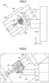
Fig. 7] Fig. 7 is a plan view illustrating a configuration of a gate rotor as a comparative example. - [
Fig. 8] Fig. 8 is a plan view illustrating a relative angle of a cutting tool with respect to a center axis of a screw rotor as the comparative example. - [
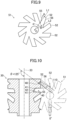
Fig. 9] Fig. 9 is a plan view illustrating a configuration of each of the gate rotors. - [
Fig. 10] Fig. 10 is a plan view illustrating a relative angle of the cutting tool with respect to the center axis of the screw rotor. - [
Fig. 11] Fig. 11 is a diagram illustrating the shapes of corner portions between side wall surfaces of helical grooves and bottom wall surfaces of the helical grooves. - [
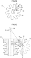
Fig. 12] Fig. 12 is a plan view illustrating a configuration of a gate rotor according to a second embodiment. - [
Fig. 13] Fig. 13 is a plan view illustrating a relative angle of the cutting tool with respect to the center axis of the screw rotor. - [
Fig. 14] Fig. 14 is a plan view illustrating the configuration of the gate rotor according to a third embodiment. - [
Fig. 15] Fig. 15 is a plan view illustrating a relative angle of the cutting tool with respect to the center axis of the screw rotor. - [
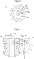
Fig. 16] Fig. 16 is a plan view illustrating a configuration of a gate rotor according to a fourth embodiment. - [
Fig. 17] Fig. 17 is a plan view illustrating a relative angle of the cutting tool with respect to the center axis of the screw rotor. - As illustrated in
Fig. 1 , a screw compressor (10) is included in a refrigeration apparatus (1). The refrigeration apparatus (1) includes a refrigerant circuit (1a) filled with a refrigerant. The refrigerant circuit (1a) includes the screw compressor (10), a radiator (3), a decompression mechanism (4), and an evaporator (5). The decompression mechanism (4) is, for example, an expansion valve. The refrigerant circuit (1a) performs a vapor compression refrigeration cycle. - The refrigeration apparatus (1) is an air-conditioning device. The air-conditioning device may be a cooling-only device, a heating-only device, or an air-conditioning device that switches between cooling and heating. In this case, the air-conditioning device includes a switching mechanism (e.g., a four-way switching valve) that switches a direction in which the refrigerant circulates. The refrigeration apparatus (1) may be, for example, a water heater, a chiller unit, or a cooling apparatus that cools the air therein. The cooling apparatus cools the air inside a refrigerator, a freezer, a container, or the like.
- As illustrated in
Fig. 2 andFig. 3 , the screw compressor (10) includes a single screw rotor (30) and two gate rotor assemblies (50). The screw compressor (10) includes a casing (11), an electric motor (17), and a drive shaft (18). - As illustrated in
Fig. 2 , the casing (11) is formed in a cylindrical shape with both ends closed. The casing (11) is positioned such that the longitudinal direction thereof is a substantially horizontal direction. The casing (11) includes a cylindrical portion (16). The cylindrical portion (16) is a portion that is formed in a cylindrical shape. The cylindrical portion (16) is positioned in the vicinity of the center of the casing (11) in the longitudinal direction. The screw rotor (30) is accommodated in the cylindrical portion (16). - The casing (11) has a suction port (12) and a discharge port (13). The suction port (12) is formed at an upper portion of a first end portion (a left end portion in
Fig. 2 ) of the casing (11). The discharge port (13) is formed in an upper portion of a second end portion (a right end portion inFig. 2 ) of the casing (11). - The casing (11) includes a low-pressure chamber (14) and a high-pressure chamber (15) formed therein. The low-pressure chamber (14) is formed closer to the first end of the casing (11) than the cylindrical portion (16) is and communicates with the suction port (12). The high-pressure chamber (15) is formed closer to the second end of the casing (11) than the cylindrical portion (16) is and communicates with the discharge port (13).
- The electric motor (17) is disposed in the low-pressure chamber (14). The drive shaft (18) connects the electric motor (17) and the screw rotor (30) to each other. The electric motor (17) drives the screw rotor (30) so that the screw rotor (30) rotates.
- As illustrated in
Fig. 3 , each of the gate rotor assemblies (50) includes a gate rotor (51) and a support (54). Each of the gate rotors (51) is a member that is made of a resin and that has a flat plate-like shape. Each of the supports (54) is a member made of a metal. Each of the supports (54) is provided so as to be in contact with a rear surface of the corresponding gate rotor (51) and supports the gate rotor (51). - In
Fig. 3 , in one of the gate rotor assemblies (50) that is located on the right-hand side of the screw rotor (30), a front surface of the gate rotor (51) faces upward. In addition, inFig. 3 , in the other of the gate rotor assemblies (50) that is located on the left-hand side of the screw rotor (30), a front surface of the gate rotor (51) faces downward. - As illustrated in
Fig. 4 , the screw rotor (30) is a member that is made of a metal and that has a cylindrical shape. In the axial direction of the screw rotor (30), a first seal end portion (31) is provided at one end of the screw rotor (30), and a second seal end portion (32) is provided at the other end of the screw rotor (30). The lower end portion of the screw rotor (30) inFig. 4 corresponds to the first seal end portion (31), and the upper end portion of the screw rotor (30) inFig. 4 corresponds to the second seal end portion (32). In the cylindrical portion (16) of the casing (11), the first seal end portion (31) of the screw rotor (30) is located on the high-pressure chamber (15) side, and the second seal end portion (32) of the screw rotor (30) is located on the low-pressure chamber (14) side. - The screw rotor (30) has a plurality of helical grooves (40). The helical grooves (40) are formed in an outer peripheral portion of the screw rotor (30). The helical grooves (40) extend in a helical manner in a direction in which a center axis (33) of the screw rotor (30) extends. The helical grooves (40) are formed between the first seal end portion (31) and the second seal end portion (32). The helical grooves (40) are open only at the outer peripheral surface of the screw rotor (30). Therefore, in the screw rotor (30) of the present embodiment, each of the helical grooves (40) is not open at an end surface of the screw rotor (30). Each of the helical grooves (40) has side wall surfaces (41) and a bottom wall surface (42).
- As illustrated in
Fig. 4 , each of the gate rotors (51) includes a plurality of gates (52) that are arranged in such a manner as to be spaced apart from each other in a circumferential direction. Each of the gates (52) is a substantially rectangular flat plate-shaped portion. The gates (52) enter the helical grooves (40) of the screw rotor (30) and slide on wall surfaces of the helical grooves (40) so as to form a first compression chamber (21) and a second compression chamber (22). Note that the detailed shape of each of the gate rotors (51) will be described later. - Each of the gates (52) has a first seal line (55) and a second seal line (56) each of which formed at a side surface thereof. The first seal lines (55) and the second seal lines (56) are each a linear region extending from a base end of the corresponding gate (52) toward a tip end of the gate (52). When one of the gates (52) enters one of the helical grooves (40), the corresponding first seal line (55) and the corresponding second seal line (56) slide along the side wall surfaces (41) of the helical groove (40).
- When the screw rotor (30) rotates, the gate rotors (51) rotate along with the rotation of the screw rotor (30). In
Fig. 4 , the gate rotor (51) on the right-hand side rotates in the counterclockwise direction. The other gate rotor (51) on the left-hand side rotates in the clockwise direction. - As illustrated in
Fig. 2 andFig. 3 , in the screw compressor (10), the screw rotor (30), the gate rotors (51), and the cylindrical portion (16) of the casing (11) form the first compression chamber (21) and the second compression chamber (22). The first compression chamber (21) and the second compression chamber (22) are closed spaces that are surrounded by the wall surfaces of the helical grooves (40) of the screw rotor (30), the front surfaces of the gates (52) of the gate rotors (51), and the inner peripheral surface of the cylindrical portion (16). - In the screw compressor (10) of the present embodiment, a compression chamber that is located below the screw rotor (30) in
Fig. 3 corresponds to the first compression chamber (21), and a compression chamber that is located above the screw rotor (30) inFig. 3 corresponds to the second compression chamber (22). - In the screw compressor (10), the screw rotor (30) is driven by the electric motor (17). When the screw rotor (30) rotates, the gate rotors (51) meshing with the screw rotor (30) rotate. When the gate rotors (51) rotate, the gates (52) of the gate rotors (51) enter the helical grooves (40) of the screw rotor (30) and relatively move from a suction-side end of the helical grooves (40) that the gates (52) have entered toward a discharge-side end of the helical grooves (40). As a result, the volume of the first compression chamber (21) and the volume of the second compression chamber (22) are gradually reduced, and the refrigerant in the first and second compression chambers (21) and (22) is compressed.
- The screw compressor (10) of the present embodiment performs two-stage compression. More specifically, the refrigerant that has flowed in the low-pressure chamber (14) through the suction port (12) flows into the first compression chamber (21) and is compressed. The refrigerant compressed in the first compression chamber (21) is discharged from the first compression chamber (21) and flows into the second compression chamber (22) through a passage that is formed in the casing (11). The refrigerant that has flowed in the second compression chamber (22) is compressed and then discharged to the high-pressure chamber (15). The refrigerant that has flowed in the high-pressure chamber (15) is discharged to the outside of the screw compressor (10) through the discharge port (13).
- A method of manufacturing the screw rotor (30) of the present embodiment will now be described.
- As illustrated in
Fig. 5 , the screw rotor (30) is processed by using a 5-axis machining center (100). - The 5-axis machining center (100) includes a spindle (101) to which a cutting tool (110), such as an end mill, is attached and a column (102) to which the spindle (101) is attached. The 5-axis machining center (100) further includes a rotary table (104) that is rotatably attached to a base table (103) and a holder (105) that is placed on the rotary table (104) so as to hold the screw rotor (30), which is a workpiece.
- In the 5-axis machining center (100), three degrees of freedom are assigned to the cutting tool (110) side, and two degrees of freedom are assigned to the screw rotor (30) side. More specifically, the spindle (101) is freely movable in the X-axis direction that is orthogonal to an axis of the spindle (101), in the Y-axis direction that is orthogonal to the axis and the X-axis direction, and in the Z-axis direction that is the direction in which the axis extends.
- The holder (105) is freely rotatable about its center axis (about an A-axis). The rotary table (104) to which the holder (105) is attached is freely rotatable around an axis (a B-axis) that is orthogonal to the axial direction of the holder (105).
- In other words, in the 5-axis machining center (100), the cutting tool (110) is capable of performing translational movement in the X-axis direction, the Y-axis direction, and the Z-axis direction, and the screw rotor (30) is freely rotatable around the A-axis and the B-axis.
- In the 5-axis machining center (100), machining of the screw rotor (30) is performed by moving the cutting tool (110) on the basis of a tool path that is provided beforehand as numerical data. The 5-axis machining center (100) sequentially performs a plurality of processes from rough cutting to a finishing step by using a plurality of types of the cutting tools (110).
- As illustrated in
Fig. 6 , the relative angle θ of the cutting tool (110) with respect to the center axis (33) of the screw rotor (30) reaches its maximum value (e.g., 150 degrees) when an axial end of each of the helical grooves (40) is machined. Thus, the range of a tool orientation required for the cutting tool (110) to machine the helical grooves (40) of the general screw rotor (30) is 25 degrees to 150 degrees with respect to the center axis (33) of the screw rotor (30). - However, in the general 5-axis machining center (100), the relative angle θ of the cutting tool (110) with respect to the center axis (33) of the screw rotor (30) is within an operating range up to 135 degrees, and the holder (105) on the rotary table (104) and a main body of the spindle (101) interfere with each other.
- In addition, even if the special 5-axis machining center (100) in which the relative angle θ of the cutting tool (110) with respect to the center axis (33) of the screw rotor (30) is within an operating range up to 145 degrees is used, the interference between the spindle (101) and the rotary table (104) cannot be avoided. Consequently, an additional operation to change the holding position of the screw rotor (30) with respect to the holder (105) is required during the finishing step, which increases the workload.
- Accordingly, the inventors of the present application conducted studies on refining the shape of each of the gates (52) to avoid the interference between the spindle (101) and the rotary table (104) when machining each of the helical grooves (40), which correspond to the gates (52), by using the 5-axis machining center (100).
- First, as a comparative example, the shape of each of the general gates (52) will be described. As illustrated in
Fig. 7 , each of the gate rotors (51) includes the gates (52) that mesh with the helical grooves (40) of the screw rotor (30). Each of the gates (52) includes the first seal line (55) and the second seal line (56) that come into contact with the side wall surfaces (41) of the helical grooves (40) of the screw rotor (30). - In each of the gates (52), the shape of the first seal line (55) and the shape of the second seal line (56) are symmetric with respect to a first imaginary straight line (L1) passing through a rotation center (O) of the corresponding gate rotor (51) and a first intermediate position (A) that is located on the tip end side of the gate (52) between the first seal line (55) and the second seal line (56).
- In addition, a second imaginary straight line (L2) passing through the rotation center (O) of a corresponding one of the gate rotors (51) and a second intermediate position (B) that is located on the base end side of the gate (52) between the first seal line (55) and the second seal line (56) coincides with the first imaginary straight line (L1). Thus, the angle formed by the first imaginary straight line (L1) and the second imaginary straight line (L2) is 0 degrees.
- As illustrated in
Fig. 8 , a groove machining step of forming the helical grooves (40), whose shapes correspond to the gates (52), into a cylindrical workpiece is performed. After the groove machining step, the finishing step is performed on the side wall surfaces (41) and the bottom wall surfaces (42) of the helical grooves (40) such that the shapes of the helical grooves (40) each meet the design values of the screw rotor (30). In the finishing step, swarf machining in which the screw rotor (30) is cut by using a side surface of the cutting tool (110) is performed. - Here, as illustrated in
Fig. 8 , assume that the relative angle θ of the cutting tool (110) with respect to the center axis (33) of the screw rotor (30) is 0 degrees when a center axis of the cutting tool (110) and the center axis (33) of the screw rotor (30) are parallel to each other while the tip of the cutting tool (110) faces downward inFig. 8 . - A maximum angle of the cutting tool (110) when machining an axial end portion of the screw rotor (30) corresponds to the shape of each of the gates (52). In the case illustrated in
Fig. 8 , the maximum angle of the cutting tool (110) is 150 degrees. Thus, even if the special 5-axis machining center (100) in which the relative angle θ of the cutting tool (110) with respect to the center axis (33) of the screw rotor (30) is within an operating range up to 145 degrees is used, the interference between the spindle (101) and the rotary table (104) cannot be avoided. - Next, the shape of each of the gates (52) according to the present embodiment will be described. As illustrated in
Fig. 9 , each of the gate rotors (51) includes the gates (52) that mesh with the helical grooves (40) of the screw rotor (30). Each of the gates (52) includes the first seal line (55) and the second seal line (56) that come into contact with the side wall surfaces (41) of the helical grooves (40) of the screw rotor (30). - In each of the gates (52), the shape of the first seal line (55) and the shape of the second seal line (56) are asymmetric with respect to the first imaginary straight line (L1) passing through the rotation center (O) of the corresponding gate rotor (51) and the first intermediate position (A) located on the tip end side of the gate (52) between the first seal line (55) and the second seal line (56) .
- In addition, the second imaginary straight line (L2) passing through the rotation center (O) of the corresponding gate rotor (51) and the second intermediate position (B) located on the base end side of the gate (52) between the first seal line (55) and the second seal line (56) is inclined at a predetermined angle with respect to the first imaginary straight line (L1). An angle formed by the first imaginary straight line (L1) and the second imaginary straight line (L2) will be referred to as an angle α.
- As illustrated in
Fig. 10 , the groove machining step of forming the helical grooves (40), whose shapes correspond to the gates (52), into a cylindrical workpiece is performed. After the groove machining step, the finishing step is performed on the side wall surfaces (41) and the bottom wall surfaces (42) of the helical grooves (40) such that the shapes of the helical grooves (40) each meet the design values of the screw rotor (30). In the finishing step, swarf machining in which the screw rotor (30) is cut by using the side surface of the cutting tool (110) is performed. - Here, as illustrated in
Fig. 10 , assume that the relative angle θ of the cutting tool (110) with respect to the center axis (33) of the screw rotor (30) is 0 degrees when the center axis of the cutting tool (110) and the center axis (33) of the screw rotor (30) are parallel to each other while the tip of the cutting tool (110) faces downward inFig. 10 . - Here, when viewed in an axial direction of the gate rotor (51), a maximum angle formed by the center axis (33) of the screw rotor (30) and a surface included in the side wall surfaces (41) of the helical grooves (40), the surface being configured to come into contact with the first seal line (55) of one of the gates (52), that is, the maximum angle of the cutting tool (110) when machining the axial end portion of the screw rotor (30), corresponds to the shape of the gate (52). In the case illustrated in
Fig. 10 , the angle α formed by the first imaginary straight line (L1) and the second imaginary straight line (L2) in each of the gates (52) is designed such that the maximum angle of the cutting tool (110) is 125 degrees. - As described above, when each of the gates (52) has the shape illustrated in
Fig. 9 and Fig. 10 , the finishing step is performed with the relative angle θ of the cutting tool (110) within the range of 25 degrees to 125 degrees. As a result, the interference between the spindle (101) and the rotary table (104) can be avoided when machining each of the helical grooves (40) by using the 5-axis machining center (100) . - Here, as illustrated in
Fig. 11 , corner portions between the side wall surfaces (41) of the helical grooves (40) that come into contact with the first seal lines (55) of the gates (52) and the bottom wall surfaces (42) of the helical grooves (40) each have an acute angle, and they cannot be processed at an acute angle. Thus, the corner portions between the side wall surfaces (41) and the bottom wall surfaces (42) of the helical grooves (40) are each formed into a curved shape by using a taper end mill. For example, the curvature of each of the curved shapes connecting the side wall surfaces (41) to their respective bottom wall surfaces (42) may be equivalent to the outer diameter of each of the gate rotors (51). Note that it is also necessary to chamfer corner portions of the gates (52) on the tip end side in accordance with the curved shapes of the corner portions of the helical grooves (40). - According to the features of the present embodiment, in each of the gates (52), the first seal line (55) and the second seal line (56) are asymmetric with respect to the first imaginary straight line (L1) passing through the rotation center (O) of a corresponding one of the gate rotors (51) and the first intermediate position (A) located on the tip end side of the gate (52) between the first seal line (55) and the second seal line (56), and each of the helical grooves (40) has a shape corresponding to the gate (52). As described above, by refining the shape of each of the gates (52), the interference between the spindle (101) and the rotary table (104) can be avoided when machining each of the helical grooves (40), which correspond to the gates (52), by using the 5-axis machining center (100).
- According to the features of the present embodiment, the second imaginary straight line (L2) passing through the rotation center (O) of the corresponding gate rotor (51) and the second intermediate position (B) located on the base end side of the gate (52) between the first seal line (55) and the second seal line (56) is inclined at a predetermined angle with respect to the first imaginary straight line (L1). As described above, by refining the shape of each of the gates (52), the interference between the spindle (101) and the rotary table (104) can be avoided when machining each of the helical grooves (40), which correspond to the gates (52), by using the 5-axis machining center (100).
- According to the features of the present embodiment, the corner portions between the bottom wall surfaces (42) and the side wall surfaces (41) of the helical grooves (40) each have a curved shape, so that the helical grooves (40) can be formed by using a taper end mill.
- According to the features of the present embodiment, the helical grooves (40) can be formed between the first seal end portion (31) and the second seal end portion (32) even in the case where the screw rotor (30) has seal surfaces at the two axial ends thereof.
- According to the features of the present embodiment, the screw compressor (10) and the refrigerant circuit (1a) through which the refrigerant compressed by the screw compressor (10) flows are provided. As a result, the refrigeration apparatus (1) including the screw compressor (10) can be provided.
- In the following description, portions that are the same as those of the above-described first embodiment will be denoted by the same reference signs, and only differences will be described.
- As illustrated in
Fig. 12 , each of the gate rotors (51) includes the gates (52) that mesh with the helical grooves (40) of the screw rotor (30). Each of the gates (52) includes the first seal line (55) and the second seal line (56) that come into contact with the side wall surfaces (41) of the helical grooves (40) of the screw rotor (30). - In each of the gates (52), the shape of the first seal line (55) and the shape of the second seal line (56) are asymmetric with respect to the first imaginary straight line (L1) passing through the rotation center (O) of the corresponding gate rotor (51) and the first intermediate position (A) located on the tip end side of the gate (52) between the first seal line (55) and the second seal line (56) .
- In addition, the second imaginary straight line (L2) passing through the rotation center (O) of the corresponding gate rotor (51) and the second intermediate position (B) located on the base end side of the gate (52) between the first seal line (55) and the second seal line (56) is inclined at a predetermined angle with respect to the first imaginary straight line (L1). The angle formed by the first imaginary straight line (L1) and the second imaginary straight line (L2) will be referred to as the angle α.
- As illustrated in
Fig. 13 , assume that the relative angle θ of the cutting tool (110) with respect to the center axis (33) of the screw rotor (30) is 0 degrees when the center axis of the cutting tool (110) and the center axis (33) of the screw rotor (30) are parallel to each other while the tip of the cutting tool (110) faces downward inFig. 13 . - The maximum angle of the cutting tool (110) when machining the axial end portion of the screw rotor (30) corresponds to the shape of each of the gates (52). In the case illustrated in
Fig. 13 , the angle α formed by the first imaginary straight line (L1) and the second imaginary straight line (L2) in each of the gates (52) is designed such that the maximum angle of the cutting tool (110) is 145 degrees. The angle α in each of the gates (52) illustrated inFig. 12 is smaller than the angle α in each of the gates (52) of the first embodiment in which the maximum angle of the cutting tool (110) is 125 degrees. - As described above, when each of the gates (52) has the shape illustrated in
Fig. 12 and Fig. 13 , the finishing step is performed with the relative angle θ of the cutting tool (110) within the range of 25 degrees to 145 degrees. As described above, by setting the maximum angle of the cutting tool (110) to be 145 degrees or less, the interference between the spindle (101) and the rotary table (104) can be avoided when machining each of the helical grooves (40), which correspond to the gates (52), by using the 5-axis machining center (100). - As illustrated in
Fig. 14 , each of the gate rotors (51) includes the gates (52) that mesh with the helical grooves (40) of the screw rotor (30). Each of the gates (52) includes the first seal line (55) and the second seal line (56) that come into contact with the side wall surfaces (41) of the helical grooves (40) of the screw rotor (30). - In each of the gates (52), the shape of the first seal line (55) and the shape of the second seal line (56) are asymmetric with respect to the first imaginary straight line (L1) passing through the rotation center (O) of the corresponding gate rotor (51) and the first intermediate position (A) located on the tip end side of the gate (52) between the first seal line (55) and the second seal line (56) .
- In addition, the second imaginary straight line (L2) passing through the rotation center (O) of the corresponding gate rotor (51) and the second intermediate position (B) located on the base end side of the gate (52) between the first seal line (55) and the second seal line (56) is inclined at a predetermined angle with respect to the first imaginary straight line (L1). The angle formed by the first imaginary straight line (L1) and the second imaginary straight line (L2) will be referred to as the angle α.
- As illustrated in
Fig. 15 , assume that the relative angle θ of the cutting tool (110) with respect to the center axis (33) of the screw rotor (30) is 0 degrees when the center axis of the cutting tool (110) and the center axis (33) of the screw rotor (30) are parallel to each other while the tip of the cutting tool (110) faces downward inFig. 15 . - The maximum angle of the cutting tool (110) when machining the axial end portion of the screw rotor (30) corresponds to the shape of each of the gates (52). In the case illustrated in
Fig. 15 , the angle α formed by the first imaginary straight line (L1) and the second imaginary straight line (L2) in each of the gates (52) is designed such that the maximum angle of the cutting tool (110) is 135 degrees. The angle α in each of the gates (52) illustrated inFig. 14 is smaller than the angle α in each of the gates (52) of the first embodiment in which the maximum angle of the cutting tool (110) is 125 degrees and is larger than the angle α in each of the gates (52) of the second embodiment in which the maximum angle of the cutting tool (110) is 145 degrees. - As described above, when each of the gates (52) has the shape illustrated in
Fig. 14 and Fig. 15 , the finishing step is performed with the relative angle θ of the cutting tool (110) within the range of 25 degrees to 135 degrees. As described above, by setting the maximum angle of the cutting tool (110) to be 135 degrees or less, the interference between the spindle (101) and the rotary table (104) can be avoided when machining each of the helical grooves (40), which correspond to the gates (52), by using the 5-axis machining center (100). - As illustrated in
Fig. 16 , each of the gate rotors (51) includes the gates (52) that mesh with the helical grooves (40) of the screw rotor (30). Each of the gates (52) includes the first seal line (55) and the second seal line (56) that come into contact with the side wall surfaces (41) of the helical grooves (40) of the screw rotor (30). - In each of the gates (52), the shape of the first seal line (55) and the shape of the second seal line (56) are asymmetric with respect to the first imaginary straight line (L1) passing through the rotation center (O) of the corresponding gate rotor (51) and the first intermediate position (A) located on the tip end side of the gate (52) between the first seal line (55) and the second seal line (56) .
- In addition, the second imaginary straight line (L2) passing through the rotation center (O) of the corresponding gate rotor (51) and the second intermediate position (B) located on the base end side of the gate (52) between the first seal line (55) and the second seal line (56) is inclined at a predetermined angle with respect to the first imaginary straight line (L1). The angle formed by the first imaginary straight line (L1) and the second imaginary straight line (L2) will be referred to as the angle α.
- As illustrated in
Fig. 17 , assume that the relative angle θ of the cutting tool (110) with respect to the center axis (33) of the screw rotor (30) is 0 degrees when the center axis of the cutting tool (110) and the center axis (33) of the screw rotor (30) are parallel to each other while the tip of the cutting tool (110) faces downward inFig. 17 . - The maximum angle of the cutting tool (110) when machining the axial end portion of the screw rotor (30) corresponds to the shape of each of the gates (52). In the case illustrated in
Fig. 17 , the angle α formed by the first imaginary straight line (L1) and the second imaginary straight line (L2) in each of the gates (52) is designed such that the maximum angle of the cutting tool (110) is 120 degrees. The angle α in each of the gates (52) illustrated inFig. 16 is larger than the angle α in each of the gates (52) of the first embodiment in which the maximum angle of the cutting tool (110) is 125 degrees. - As described above, when each of the gates (52) has the shape illustrated in
Fig. 16 and Fig. 17 , the finishing step is performed with the relative angle θ of the cutting tool (110) within the range of 25 degrees to 120 degrees. As described above, by setting the maximum angle of the cutting tool (110) to be 120 degrees or less, the interference between the spindle (101) and the rotary table (104) can be avoided when machining each of the helical grooves (40), which correspond to the gates (52), by using the 5-axis machining center (100). - Although the embodiments and the modifications have been described above, it is to be understood that various modifications can be made to the embodiments and the details without departing from the gist and the scope of the claims. In addition, the elements according to the above-described embodiments, modifications, and other embodiments may be appropriately combined or replaced. Furthermore, in the specification and the claims, the terms "first", "second", "third", and the like are used to distinguish between the terms to which they refer, and are not intended to limit the number or order of those terms.
- As described above, the present disclosure is useful for a screw compressor and a refrigeration apparatus. Reference Signs List
-
- 1
- refrigeration apparatus
- 1a
- refrigerant circuit
- 10
- screw compressor
- 30
- screw rotor
- 31
- first seal end portion
- 32
- second seal end portion
- 33
- center axis
- 40
- helical groove
- 41
- side wall surface
- 42
- bottom wall surface
- 51
- gate rotor
- 52
- gate
- 55
- first seal line
- 56
- second seal line
- A
- first intermediate position
- B
- second intermediate position
- L1
- first imaginary straight line
- L2
- second imaginary straight line
- O
- rotation center
Claims (8)
- A screw compressor comprising:a screw rotor (30) having a plurality of helical grooves (40); anda gate rotor (51) including gates (52) configured to mesh with the helical grooves (40) of the screw rotor (30),wherein each of the gates (52) has a first seal line (55) and a second seal line (56) each configured to come into contact with side wall surfaces (41) of the helical grooves (40) of the screw rotor (30),wherein a shape of the first seal line (55) and a shape of the second seal line (56) are asymmetric with respect to a first imaginary straight line (L1) passing through a rotation center (O) of the gate rotor (51) and a first intermediate position (A) located on a tip end side of each of the gates (52) between the first seal line (55) and the second seal line (56), andwherein each of the helical grooves (40) has a shape corresponding to each of the gates (52).
- The screw compressor according to claim 1,
wherein a second imaginary straight line (L2) passing through a rotation center (O) of the gate rotor (51) and a second intermediate position (B) located on a base end side of each of the gates (52) between the first seal line (55) and the second seal line (56) is inclined at a predetermined angle with respect to the first imaginary straight line (L1) . - The screw compressor according to claim 1 or 2,
wherein, when viewed in an axial direction of the gate rotor (51), a maximum angle formed by a center axis (33) of the screw rotor (30) and a surface included in the side wall surfaces (41) of the helical grooves (40), the surface being configured to come into contact with the first seal line (55), is 145 degrees or less. - The screw compressor according to claim 3,
wherein the maximum angle is 135 degrees or less. - The screw compressor according to claim 4,
wherein the maximum angle is 120 degrees or less. - The screw compressor according to any one of claims 1 to 5,
wherein, in each of the helical grooves (40), a corner portion between a bottom wall surface (42) and a side wall surface (41) is formed in a curved shape. - The screw compressor according to any one of claims 1 to 6,wherein, in an axial direction of the screw rotor (30), a first seal end portion (31) is provided at one end of the screw rotor (30), and a second seal end portion (32) is provided at another end of the screw rotor (30), andwherein the helical grooves (40) are formed between the first seal end portion (31) and the second seal end portion (32) .
- A refrigeration apparatus comprising:the screw compressor (10) according to any one of claims 1 to 7; anda refrigerant circuit (1a) configured to allow a refrigerant compressed by the screw compressor (10) to flow therethrough.
Applications Claiming Priority (2)
| Application Number | Priority Date | Filing Date | Title |
|---|---|---|---|
| JP2022051422A JP7360065B1 (en) | 2022-03-28 | 2022-03-28 | Screw compressor and refrigeration equipment |
| PCT/JP2023/005938 WO2023188988A1 (en) | 2022-03-28 | 2023-02-20 | Screw compressor and refrigeration device |
Publications (3)
| Publication Number | Publication Date |
|---|---|
| EP4477886A1 true EP4477886A1 (en) | 2024-12-18 |
| EP4477886A4 EP4477886A4 (en) | 2025-06-18 |
| EP4477886B1 EP4477886B1 (en) | 2026-04-29 |
Family
ID=88200373
Family Applications (1)
| Application Number | Title | Priority Date | Filing Date |
|---|---|---|---|
| EP23779018.3A Active EP4477886B1 (en) | 2022-03-28 | 2023-02-20 | Screw compressor and refrigeration device |
Country Status (5)
| Country | Link |
|---|---|
| US (1) | US12480492B2 (en) |
| EP (1) | EP4477886B1 (en) |
| JP (1) | JP7360065B1 (en) |
| CN (1) | CN119053787B (en) |
| WO (1) | WO2023188988A1 (en) |
Family Cites Families (15)
| Publication number | Priority date | Publication date | Assignee | Title |
|---|---|---|---|---|
| US3945778A (en) * | 1974-10-22 | 1976-03-23 | Bernard Zimmern | Compressors and expansion machines of the single worm type |
| JP3807922B2 (en) * | 1999-10-26 | 2006-08-09 | チァ シリィアン | Single screw compressor with non-equal width teeth |
| CN1231676C (en) * | 2002-04-04 | 2005-12-14 | 邹汉华 | All-extricated contact line single helical-lobe compressor intermeshing pair |
| JP4169069B2 (en) * | 2006-11-24 | 2008-10-22 | ダイキン工業株式会社 | Compressor |
| US8348649B2 (en) | 2007-08-07 | 2013-01-08 | Daikin Industries, Ltd. | Single screw compressor and a method for processing a screw rotor |
| WO2009028127A1 (en) * | 2007-08-31 | 2009-03-05 | Daikin Industries, Ltd. | Screw rotor working method, working apparatus, and screw rotor |
| CN101424266B (en) * | 2008-12-22 | 2010-12-15 | 李锦上 | Oblique star wheel single screw compressor |
| JP2010196582A (en) * | 2009-02-25 | 2010-09-09 | Daikin Ind Ltd | Single screw compressor |
| JP2011021574A (en) * | 2009-07-17 | 2011-02-03 | Mitsui Seiki Kogyo Co Ltd | Structure for compression chamber in screw compressor having single gate rotor |
| CN101922346A (en) * | 2010-01-13 | 2010-12-22 | 李锦上 | Single-screw rotary engine and energy conversion method thereof |
| CN102102670B (en) * | 2010-09-13 | 2013-07-17 | 李锦上 | Three-face concurrent construction method and star wheel of single screw compressor constructed by same |
| CN104405830B (en) * | 2014-09-17 | 2017-02-15 | 西安交通大学 | Collaborative construction method for cylindrical envelope molded lines of two side faces of star wheel teeth |
| EP3540228B1 (en) * | 2017-02-20 | 2024-03-20 | Daikin Industries, Ltd. | Screw compressor |
| JP7429570B2 (en) * | 2020-03-10 | 2024-02-08 | 三井精機工業株式会社 | Manufacturing method and design method of screw rotor |
| EP4105486A4 (en) | 2020-03-31 | 2024-04-10 | Daikin Industries, Ltd. | SCREW COMPRESSOR AND REFRIGERATION DEVICE |
-
2022
- 2022-03-28 JP JP2022051422A patent/JP7360065B1/en active Active
-
2023
- 2023-02-20 WO PCT/JP2023/005938 patent/WO2023188988A1/en not_active Ceased
- 2023-02-20 EP EP23779018.3A patent/EP4477886B1/en active Active
- 2023-02-20 CN CN202380029825.3A patent/CN119053787B/en active Active
-
2024
- 2024-09-20 US US18/892,129 patent/US12480492B2/en active Active
Also Published As
| Publication number | Publication date |
|---|---|
| EP4477886B1 (en) | 2026-04-29 |
| CN119053787A (en) | 2024-11-29 |
| WO2023188988A1 (en) | 2023-10-05 |
| CN119053787B (en) | 2026-05-05 |
| EP4477886A4 (en) | 2025-06-18 |
| US12480492B2 (en) | 2025-11-25 |
| US20250012279A1 (en) | 2025-01-09 |
| JP2023154430A (en) | 2023-10-20 |
| JP7360065B1 (en) | 2023-10-12 |
Similar Documents
| Publication | Publication Date | Title |
|---|---|---|
| US8348648B2 (en) | Single screw compressor | |
| US8348649B2 (en) | Single screw compressor and a method for processing a screw rotor | |
| CN103635729A (en) | Refrigerant flow path switching valve and air conditioner using same | |
| EP4477886B1 (en) | Screw compressor and refrigeration device | |
| AU2008236150A1 (en) | Compressor capacity control operation mechanism and air conditioner provided with same | |
| US12383966B2 (en) | Method for manufacturing screw rotor | |
| US10328544B2 (en) | Scroll machining method and scroll machining apparatus | |
| US20110008197A1 (en) | Inverter type scroll compressor | |
| JP2023144598A (en) | Screw compressor and refrigeration equipment | |
| JP2007046582A (en) | Scroll fluid machinery and refrigerating cycle using the fluid machinery | |
| US12247566B2 (en) | Screw compressor, and refrigeration apparatus | |
| JPH07299630A (en) | Method for forming scroll member | |
| JP2023144453A (en) | Method for manufacturing screw rotor | |
| JP2022075840A (en) | Screw compressor | |
| EP4477887B1 (en) | Screw compressor and freezer | |
| JP2009057920A (en) | Screw rotor processing apparatus and processing method | |
| JP2025117169A (en) | Rotary compressors and equipment | |
| JP2022108158A (en) | Compressor, air conditioner, manufacturing method of compressor and manufacturing method of air conditioner | |
| WO2020050794A2 (en) | Glass material compressor | |
| EP3252309A1 (en) | Intermediate discharge port for a compressor |
Legal Events
| Date | Code | Title | Description |
|---|---|---|---|
| STAA | Information on the status of an ep patent application or granted ep patent |
Free format text: STATUS: THE INTERNATIONAL PUBLICATION HAS BEEN MADE |
|
| PUAI | Public reference made under article 153(3) epc to a published international application that has entered the european phase |
Free format text: ORIGINAL CODE: 0009012 |
|
| STAA | Information on the status of an ep patent application or granted ep patent |
Free format text: STATUS: REQUEST FOR EXAMINATION WAS MADE |
|
| 17P | Request for examination filed |
Effective date: 20240913 |
|
| AK | Designated contracting states |
Kind code of ref document: A1 Designated state(s): AL AT BE BG CH CY CZ DE DK EE ES FI FR GB GR HR HU IE IS IT LI LT LU LV MC ME MK MT NL NO PL PT RO RS SE SI SK SM TR |
|
| P01 | Opt-out of the competence of the unified patent court (upc) registered |
Free format text: CASE NUMBER: APP_961/2025 Effective date: 20250108 |
|
| A4 | Supplementary search report drawn up and despatched |
Effective date: 20250521 |
|
| RIC1 | Information provided on ipc code assigned before grant |
Ipc: F04C 29/00 20060101ALI20250515BHEP Ipc: F04C 18/52 20060101AFI20250515BHEP |
|
| DAV | Request for validation of the european patent (deleted) | ||
| DAX | Request for extension of the european patent (deleted) | ||
| GRAP | Despatch of communication of intention to grant a patent |
Free format text: ORIGINAL CODE: EPIDOSNIGR1 |
|
| STAA | Information on the status of an ep patent application or granted ep patent |
Free format text: STATUS: GRANT OF PATENT IS INTENDED |
|
| INTG | Intention to grant announced |
Effective date: 20260113 |
|
| GRAS | Grant fee paid |
Free format text: ORIGINAL CODE: EPIDOSNIGR3 |
|
| GRAA | (expected) grant |
Free format text: ORIGINAL CODE: 0009210 |
|
| STAA | Information on the status of an ep patent application or granted ep patent |
Free format text: STATUS: THE PATENT HAS BEEN GRANTED |
|
| AK | Designated contracting states |
Kind code of ref document: B1 Designated state(s): AL AT BE BG CH CY CZ DE DK EE ES FI FR GB GR HR HU IE IS IT LI LT LU LV MC ME MK MT NL NO PL PT RO RS SE SI SK SM TR |
|
| REG | Reference to a national code |
Ref country code: CH Ref legal event code: F10 Free format text: ST27 STATUS EVENT CODE: U-0-0-F10-F00 (AS PROVIDED BY THE NATIONAL OFFICE) Effective date: 20260429 Ref country code: GB Ref legal event code: FG4D |
|
| REG | Reference to a national code |
Ref country code: IE Ref legal event code: FG4D |
|
| REG | Reference to a national code |
Ref country code: DE Ref legal event code: R096 Ref document number: 602023016360 Country of ref document: DE |