EP4477861A1 - Gas turbine engine with air/oil cooler having an airflow control baffle - Google Patents
Gas turbine engine with air/oil cooler having an airflow control baffle Download PDFInfo
- Publication number
- EP4477861A1 EP4477861A1 EP24182112.3A EP24182112A EP4477861A1 EP 4477861 A1 EP4477861 A1 EP 4477861A1 EP 24182112 A EP24182112 A EP 24182112A EP 4477861 A1 EP4477861 A1 EP 4477861A1
- Authority
- EP
- European Patent Office
- Prior art keywords
- engine
- airflow
- duct
- control baffle
- inlet
- Prior art date
- Legal status (The legal status is an assumption and is not a legal conclusion. Google has not performed a legal analysis and makes no representation as to the accuracy of the status listed.)
- Pending
Links
Images



Classifications
-
- F—MECHANICAL ENGINEERING; LIGHTING; HEATING; WEAPONS; BLASTING
- F02—COMBUSTION ENGINES; HOT-GAS OR COMBUSTION-PRODUCT ENGINE PLANTS
- F02C—GAS-TURBINE PLANTS; AIR INTAKES FOR JET-PROPULSION PLANTS; CONTROLLING FUEL SUPPLY IN AIR-BREATHING JET-PROPULSION PLANTS
- F02C7/00—Features, components parts, details or accessories, not provided for in, or of interest apart form groups F02C1/00 - F02C6/00; Air intakes for jet-propulsion plants
- F02C7/06—Arrangements of bearings; Lubricating
-
- F—MECHANICAL ENGINEERING; LIGHTING; HEATING; WEAPONS; BLASTING
- F02—COMBUSTION ENGINES; HOT-GAS OR COMBUSTION-PRODUCT ENGINE PLANTS
- F02C—GAS-TURBINE PLANTS; AIR INTAKES FOR JET-PROPULSION PLANTS; CONTROLLING FUEL SUPPLY IN AIR-BREATHING JET-PROPULSION PLANTS
- F02C7/00—Features, components parts, details or accessories, not provided for in, or of interest apart form groups F02C1/00 - F02C6/00; Air intakes for jet-propulsion plants
- F02C7/12—Cooling of plants
- F02C7/14—Cooling of plants of fluids in the plant, e.g. lubricant or fuel
-
- F—MECHANICAL ENGINEERING; LIGHTING; HEATING; WEAPONS; BLASTING
- F02—COMBUSTION ENGINES; HOT-GAS OR COMBUSTION-PRODUCT ENGINE PLANTS
- F02C—GAS-TURBINE PLANTS; AIR INTAKES FOR JET-PROPULSION PLANTS; CONTROLLING FUEL SUPPLY IN AIR-BREATHING JET-PROPULSION PLANTS
- F02C7/00—Features, components parts, details or accessories, not provided for in, or of interest apart form groups F02C1/00 - F02C6/00; Air intakes for jet-propulsion plants
- F02C7/12—Cooling of plants
- F02C7/16—Cooling of plants characterised by cooling medium
- F02C7/18—Cooling of plants characterised by cooling medium the medium being gaseous, e.g. air
-
- F—MECHANICAL ENGINEERING; LIGHTING; HEATING; WEAPONS; BLASTING
- F02—COMBUSTION ENGINES; HOT-GAS OR COMBUSTION-PRODUCT ENGINE PLANTS
- F02C—GAS-TURBINE PLANTS; AIR INTAKES FOR JET-PROPULSION PLANTS; CONTROLLING FUEL SUPPLY IN AIR-BREATHING JET-PROPULSION PLANTS
- F02C9/00—Controlling gas-turbine plants; Controlling fuel supply in air- breathing jet-propulsion plants
- F02C9/16—Control of working fluid flow
-
- F—MECHANICAL ENGINEERING; LIGHTING; HEATING; WEAPONS; BLASTING
- F05—INDEXING SCHEMES RELATING TO ENGINES OR PUMPS IN VARIOUS SUBCLASSES OF CLASSES F01-F04
- F05D—INDEXING SCHEME FOR ASPECTS RELATING TO NON-POSITIVE-DISPLACEMENT MACHINES OR ENGINES, GAS-TURBINES OR JET-PROPULSION PLANTS
- F05D2260/00—Function
- F05D2260/20—Heat transfer, e.g. cooling
- F05D2260/213—Heat transfer, e.g. cooling by the provision of a heat exchanger within the cooling circuit
-
- F—MECHANICAL ENGINEERING; LIGHTING; HEATING; WEAPONS; BLASTING
- F05—INDEXING SCHEMES RELATING TO ENGINES OR PUMPS IN VARIOUS SUBCLASSES OF CLASSES F01-F04
- F05D—INDEXING SCHEME FOR ASPECTS RELATING TO NON-POSITIVE-DISPLACEMENT MACHINES OR ENGINES, GAS-TURBINES OR JET-PROPULSION PLANTS
- F05D2270/00—Control
- F05D2270/30—Control parameters, e.g. input parameters
- F05D2270/303—Temperature
- F05D2270/3032—Temperature excessive temperatures, e.g. caused by overheating
Definitions
- an air/oil cooler (also referred to as a radiator) may use oil sensing thermostatic bypass valves to control the flow of cooling air. These valves sample oil within the cooler and control oil flow either through a cooling matrix or a parallel bypass channel. The valves allow or prevent cooling of oil flowing through the cooler. The valves can, over time, become unreliable.
- Some aircraft engine configurations use engine forced airflow as the cooling media in the cooler. However, using the engine airflow to induce cooling flow through a cooler can reduce engine efficiency.
- a gas turbine engine including a case; a core within the case; an exhaust nozzle that is fluidly coupled to the case; a duct having a duct outlet that is fluidly coupled to the exhaust nozzle and a duct body extending from the duct outlet to a duct inlet; an air/oil cooler having an airflow outlet disposed at the duct inlet and a cooler body extending from the airflow outlet to an airflow inlet; and an airflow control baffle disposed at one of: the duct inlet; the duct outlet; and the airflow inlet of the cooler, wherein the airflow control baffle is configured to open when oil temperature in the engine is above a first threshold and close when the oil temperature is below a second threshold that is lower than the first threshold.
- the airflow control baffle is configured to modulate between open and closed, such that it transitions between opened and closed when the temperature is between the thresholds.
- the airflow control baffle includes a first slotted plate and a second slotted plate configured to slide against the first slotted plate, between: a first position where slots in the first and second slotted plates are aligned with each other to open the airflow control baffle; and a second position where the slots in the first and second slotted plates are offset from each other to close the airflow control baffle.
- the airflow control baffle is disposed at the duct inlet or outlet.
- the airflow control baffle is disposed at the airflow inlet of the cooler.
- the engine includes an inlet nozzle that is fluidly coupled to the case.
- a gas turbine engine including: a case; a core within the case; an inlet nozzle that is fluidly coupled to the case; a duct having a duct inlet that is fluidly coupled to the inlet nozzle and a duct body extending from the duct inlet to a duct outlet; an air/oil cooler having an airflow inlet disposed at the duct outlet and a cooler body extending from the airflow inlet to an airflow outlet; and an airflow control baffle disposed at one of: the duct inlet; the duct outlet; and the airflow outlet of the cooler, wherein the airflow control baffle is configured to open when oil temperature in the engine is above a first threshold and close when the oil temperature is below a second threshold that is lower than the first threshold.
- the airflow control baffle is configured to modulate between open and closed, such that it transitions between opened and closed when the temperature is between the thresholds.
- the airflow control baffle includes a first slotted plate and a second slotted plate configured to slide against the first slotted plate between: a first position where slots in the first and second slotted plates are aligned with each other to open the airflow control baffle; and a second position where the slots in the first and second slotted plates are offset from each other to close the airflow control baffle.
- the engine includes an engine controller; a temperature sensor in the engine that is operationally coupled to the engine controller; an actuator that is operationally coupled to the engine controller and the second slotted plate of the airflow control baffle and is configured to move the second slotted plate to open or close the airflow control baffle when the oil temperature in the engine is sensed by the temperature sensor as being above the first threshold and close when the oil temperature is sensed by the temperature sensor as being is below the second threshold that is lower than the first threshold.
- airflow baffle is along an airflow path providing airflow to the cooler.
- the airflow control baffle is disposed at the duct inlet or outlet.
- the airflow control baffle is disposed at the airflow outlet of the cooler.
- the engine includes an exhaust nozzle that is fluidly coupled to the case.
- a first embodiment of cooling engine oil in gas turbine engine including monitoring, by an engine controller that is operationally coupled to a temperature sensor, oil temperature of the gas turbine engine while an airflow control baffle is closed, preventing airflow from passing through an air/oil cooler, a duct that is fluidly coupled to the cooler, and into an exhaust nozzle that is fluidly coupled to the duct, wherein the airflow control baffle is disposed at one of: a duct inlet; a duct outlet; and an airflow inlet of the cooler; determining, by the engine controller, that the oil temperature is above a first threshold; and controlling, by the engine controller, an actuator to open the airflow control baffle; monitoring, by the engine controller, the oil temperature in the engine while the airflow control baffle is opened; determining, by the engine controller, that the oil temperature is below a second threshold that is lower than the first threshold; and controlling, by the engine controller, the actuator to close the airflow control baffle.
- the method includes modulating the airflow control baffle between open and closed, such that it transitions between opened and closed when the temperature is between the thresholds.
- FIGS. 1A and 1B illustrate a gas turbine engine 100 of a type provided for use in subsonic flight, generally including, in serial flow communication, a fan 12 through which ambient air is propelled toward an inlet 32, and a core 33 including a compressor section 14 for pressurizing the air, a combustor 16 in which the compressed air is mixed with fuel and ignited for generating an annular stream of hot combustion gases, and a turbine section 18 for extracting energy from the combustion gases, which exit via an exhaust 36.
- a gas turbine engine 100 of a type provided for use in subsonic flight, generally including, in serial flow communication, a fan 12 through which ambient air is propelled toward an inlet 32, and a core 33 including a compressor section 14 for pressurizing the air, a combustor 16 in which the compressed air is mixed with fuel and ignited for generating an annular stream of hot combustion gases, and a turbine section 18 for extracting energy from the combustion gases, which exit via an exhaust 36.
- High-pressure rotor(s) of the turbine section 18 (referred to as “HP turbine rotor(s) 20") are drivingly engaged to high-pressure rotor(s) of the compressor section 14 (referred to as “HP compressor rotor(s) 22") through a high-pressure shaft 24.
- the turbine section 18 includes a vane 19 between the combustor 16 and the HP turbine rotor(s) 20.
- An airflow control baffle (for simplicity, a baffle) 200 is provided to control airflow through the cooler 60 and into the exhaust nozzle 50.
- the baffle 200 may include an electronically controlled actuator 210, which may be controlled by the engine controller 110.
- the actuator 210 controls the baffle 200 based on sensed temperature of the engine oil with a sensor 201 that is operationally coupled to the controller 110.
- the sensor 201 may be in the core 33, though it may be at another place in the engine where the temperature control is critical, such that the sensor 201 informs the motion of the airflow baffle 200 to increase/decrease a flow of cooling air 115 to cool the oil. That is, the actuator 210 may control the baffle 200 to allow cooling flow or prevent flow from traveling past the baffle 200.
- the baffle 200 may be positioned at one of several locations to prevent flow through the cooler 60 and into the exhaust nozzle 50, including the duct inlet 150, the duct outlet 140, and the airflow inlet 190 of the cooler 60.
- the baffle 200 is configured to open when oil temperature is above a first threshold and needs to be cooled.
- the baffle 200 is configured to close when the oil temperature is below a second threshold that is lower than the first threshold such that the oil does not need to be cooled.
- an induced airflow 116 through the duct 70 from the airflow 115 into and around the engine 100, enables cooling of oil flowing through the cooler 60.
Landscapes
- Engineering & Computer Science (AREA)
- Chemical & Material Sciences (AREA)
- Combustion & Propulsion (AREA)
- Mechanical Engineering (AREA)
- General Engineering & Computer Science (AREA)
- Physics & Mathematics (AREA)
- Fluid Mechanics (AREA)
- Lubrication Of Internal Combustion Engines (AREA)
Abstract
A gas turbine engine (100) according to a first embodiment, having a case (40); a core (33) within the case (40); an exhaust nozzle (50) that is fluidly coupled to the case (40); a duct (70) having a duct outlet (140) that is fluidly coupled to the exhaust nozzle (50) and a duct body (155) extending from the duct outlet (140) to a duct inlet (150); an air/oil cooler (60) having an airflow outlet (170) disposed at the duct inlet (150) and a cooler body (180) extending from the airflow outlet (170) to an airflow inlet (190); and an airflow control baffle (200) disposed at one of the duct inlet (150); the duct outlet (140); and the airflow inlet (190) of the cooler (60), wherein the airflow control baffle (200) is configured to open when oil temperature in the engine (100) is above a first threshold and close when the oil temperature is below a second threshold that is lower than the first threshold.
Description
- Exemplary embodiments pertain to the art of oil cooling systems for gas turbine engines and more specifically to a gas turbine engine with an air/oil cooler having an airflow control baffle that controls access to a cooling airflow.
- In gas turbine engines, an air/oil cooler (also referred to as a radiator) may use oil sensing thermostatic bypass valves to control the flow of cooling air. These valves sample oil within the cooler and control oil flow either through a cooling matrix or a parallel bypass channel. The valves allow or prevent cooling of oil flowing through the cooler. The valves can, over time, become unreliable. Some aircraft engine configurations use engine forced airflow as the cooling media in the cooler. However, using the engine airflow to induce cooling flow through a cooler can reduce engine efficiency.
- Disclosed is a gas turbine engine according to a first embodiment, including a case; a core within the case; an exhaust nozzle that is fluidly coupled to the case; a duct having a duct outlet that is fluidly coupled to the exhaust nozzle and a duct body extending from the duct outlet to a duct inlet; an air/oil cooler having an airflow outlet disposed at the duct inlet and a cooler body extending from the airflow outlet to an airflow inlet; and an airflow control baffle disposed at one of: the duct inlet; the duct outlet; and the airflow inlet of the cooler, wherein the airflow control baffle is configured to open when oil temperature in the engine is above a first threshold and close when the oil temperature is below a second threshold that is lower than the first threshold.
- In addition to one or more aspects of the engine according to the first embodiment, or as an alternate, the airflow control baffle is configured to modulate between open and closed, such that it transitions between opened and closed when the temperature is between the thresholds.
- In addition to one or more aspects of the engine according to the first embodiment, or as an alternate, the airflow control baffle includes a first slotted plate and a second slotted plate configured to slide against the first slotted plate, between: a first position where slots in the first and second slotted plates are aligned with each other to open the airflow control baffle; and a second position where the slots in the first and second slotted plates are offset from each other to close the airflow control baffle.
- In addition to one or more aspects of the engine according to the first embodiment, the engine includes an engine controller; a temperature sensor in the engine that is operationally coupled to the engine controller; and an actuator that is operationally coupled to the engine controller and the second slotted plate of the airflow control baffle, and is configured to move the second slotted plate to open or close the airflow control baffle when the oil temperature in the engine is sensed by the temperature sensor as being above the first threshold and close when the oil temperature is sensed by the temperature sensor as being is below the second threshold that is lower than the first threshold.
- In addition to one or more aspects of the engine according to the first embodiment, or as an alternate, airflow baffle is along an airflow path providing airflow to the cooler.
- In addition to one or more aspects of the engine according to the first embodiment, or as an alternate, the airflow control baffle is disposed at the duct inlet or outlet.
- In addition to one or more aspects of the engine according to the first embodiment, or as an alternate, the airflow control baffle is disposed at the airflow inlet of the cooler.
- In addition to one or more aspects of the engine according to the first embodiment, the engine includes an inlet nozzle that is fluidly coupled to the case.
- Further disclosed is a gas turbine engine according to a second embodiment, including: a case; a core within the case; an inlet nozzle that is fluidly coupled to the case; a duct having a duct inlet that is fluidly coupled to the inlet nozzle and a duct body extending from the duct inlet to a duct outlet; an air/oil cooler having an airflow inlet disposed at the duct outlet and a cooler body extending from the airflow inlet to an airflow outlet; and an airflow control baffle disposed at one of: the duct inlet; the duct outlet; and the airflow outlet of the cooler, wherein the airflow control baffle is configured to open when oil temperature in the engine is above a first threshold and close when the oil temperature is below a second threshold that is lower than the first threshold.
- In addition to one or more aspects of the engine according to the second embodiment, the airflow control baffle is configured to modulate between open and closed, such that it transitions between opened and closed when the temperature is between the thresholds.
- In addition to one or more aspects of the engine according to the second embodiment, the airflow control baffle includes a first slotted plate and a second slotted plate configured to slide against the first slotted plate between: a first position where slots in the first and second slotted plates are aligned with each other to open the airflow control baffle; and a second position where the slots in the first and second slotted plates are offset from each other to close the airflow control baffle.
- In addition to one or more aspects of the engine according to the second embodiment, the engine includes an engine controller; a temperature sensor in the engine that is operationally coupled to the engine controller; an actuator that is operationally coupled to the engine controller and the second slotted plate of the airflow control baffle and is configured to move the second slotted plate to open or close the airflow control baffle when the oil temperature in the engine is sensed by the temperature sensor as being above the first threshold and close when the oil temperature is sensed by the temperature sensor as being is below the second threshold that is lower than the first threshold.
- In addition to one or more aspects of the engine according to the second embodiment, airflow baffle is along an airflow path providing airflow to the cooler.
- In addition to one or more aspects of the engine according to the second embodiment, the airflow control baffle is disposed at the duct inlet or outlet.
- In addition to one or more aspects of the engine according to the second embodiment, the airflow control baffle is disposed at the airflow outlet of the cooler.
- In addition to one or more aspects of the engine according to the second embodiment, the engine includes an exhaust nozzle that is fluidly coupled to the case.
- Further disclosed is method according to a first embodiment of cooling engine oil in gas turbine engine, including monitoring, by an engine controller that is operationally coupled to a temperature sensor, oil temperature of the gas turbine engine while an airflow control baffle is closed, preventing airflow from passing through an air/oil cooler, a duct that is fluidly coupled to the cooler, and into an exhaust nozzle that is fluidly coupled to the duct, wherein the airflow control baffle is disposed at one of: a duct inlet; a duct outlet; and an airflow inlet of the cooler; determining, by the engine controller, that the oil temperature is above a first threshold; and controlling, by the engine controller, an actuator to open the airflow control baffle; monitoring, by the engine controller, the oil temperature in the engine while the airflow control baffle is opened; determining, by the engine controller, that the oil temperature is below a second threshold that is lower than the first threshold; and controlling, by the engine controller, the actuator to close the airflow control baffle.
- In addition to one or more aspects of the method according to the first embodiment, the method includes modulating the airflow control baffle between open and closed, such that it transitions between opened and closed when the temperature is between the thresholds.
- Further disclosed is method according to a second embodiment of cooling engine oil in gas turbine engine, including monitoring, by an engine controller that is operationally coupled to a temperature sensor, oil temperature in the gas turbine engine while an airflow control baffle is closed, preventing airflow from passing from an inlet nozzle, through a duct that is fluidly coupled to the inlet nozzle, and through the cooler that is fluidly coupled to the duct, wherein the airflow control baffle is disposed at one of: a duct inlet; a duct outlet; and an airflow outlet of the cooler; determining, by the engine controller, that the oil temperature is above a first threshold; and controlling, by the engine controller, an actuator to open the airflow control baffle; monitoring, by the engine controller, the oil temperature in the engine while the airflow control baffle is opened; determining, by the engine controller, that the oil temperature is below a second threshold that is lower than the first threshold; and controlling, by the engine controller, the actuator to close the airflow control baffle.
- In addition to one or more aspects of the method according to the second embodiment, the method includes modulating the airflow control baffle between open and closed, such that it transitions between opened and closed when the temperature is between the thresholds.
- The following descriptions should not be considered limiting in any way. With reference to the accompanying drawings, like elements are numbered alike:
-
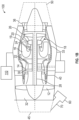
FIG. 1A shows a gas turbine engine with an air/oil cooler ducted to an exhaust nozzle of the engine; -
FIG. 1B shows a gas turbine engine with an air/oil cooler ducted to an inlet nozzle of the engine; -
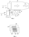
FIG. 2 shows additional aspects of the engine configuration ofFIG. 1A ; -
FIG. 3 shows aspects of a baffle utilized to control flow through the cooler; -
FIG. 4 shows additional aspects of the engine configuration ofFIG. 1B ; -
FIG. 5 shows additional aspects of the engine configuration ofFIG. 1B , with the baffle at a duct inlet and arranged in an open configuration; -
FIG. 6 shows additional aspects of the engine configuration ofFIG. 1B , with the baffle at the duct inlet and arranged in a closed configuration; -
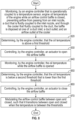
FIG. 7 is a flowchart showing a method of cooling engine oil with the engine configuration ofFIG. 1A ; and -
FIG. 8 is a flowchart showing a method of cooling engine oil with the engine configuration ofFIG. 1B . - A detailed description of one or more embodiments of the disclosed apparatus and method are presented herein by way of exemplification and not limitation with reference to the Figures.
-
FIGS. 1A and1B illustrate agas turbine engine 100 of a type provided for use in subsonic flight, generally including, in serial flow communication, afan 12 through which ambient air is propelled toward aninlet 32, and acore 33 including acompressor section 14 for pressurizing the air, acombustor 16 in which the compressed air is mixed with fuel and ignited for generating an annular stream of hot combustion gases, and aturbine section 18 for extracting energy from the combustion gases, which exit via anexhaust 36. High-pressure rotor(s) of the turbine section 18 (referred to as "HP turbine rotor(s) 20") are drivingly engaged to high-pressure rotor(s) of the compressor section 14 (referred to as "HP compressor rotor(s) 22") through a high-pressure shaft 24. Theturbine section 18 includes avane 19 between thecombustor 16 and the HP turbine rotor(s) 20. Low-pressure rotor(s) of the turbine section 18 (referred to as "LP turbine rotor(s) 26") are drivingly engaged to thefan rotor 12 and to low-pressure rotor(s) of the compressor section 14 (referred to as "LP compressor rotor(s) 30") through a low-pressure shaft 28 extending within the high-pressure shaft 24 and rotating independently therefrom. - Although illustrated as a turbofan engine, the
gas turbine engine 100 may alternatively be another type of engine, for example a turboshaft engine, also generally including in serial flow communication a compressor section, a combustor, and a turbine section, and an output shaft through which power is transferred. A turboprop engine may also apply as well as an auxiliary power unit (APU). In addition, although theengine 100 is described herein for flight applications, it should be understood that other uses, such as industrial or the like, may apply. - Control of the operation of the
engine 100 can be effected by one or more control systems, for example anengine controller 110, which is communicatively coupled to theengine 100. Theengine controller 110 can modulate a fuel flow provided to theengine 100, the position and orientation of variable geometry mechanisms within theengine 100, a bleed level of theengine 100, and the like, based on predetermined schedules or algorithms. In some embodiments, theengine controller 110 includes one or more FADEC(s), electronic engine controller(s) (EEC(s)), or the like, that are programmed to control the operation of theengine 100. The operation of theengine 100 can be controlled by way of one or more actuators, mechanical linkages, hydraulic systems, and the like. Theengine controller 110 can be coupled to the actuators, mechanical linkages, hydraulic systems, and the like, in any suitable fashion for effecting control of theengine 100. - As shown in
FIG. 1A , and explained in greater detail below, theengine 100 may have anouter case 40 with a case inlet nozzle (for simplicity, an inlet nozzle) 45 at its forward end and a case exhaust nozzle (for simplicity, an exhaust nozzle) 50 at its aft end. An air/oil cooler (for simplicity, a cooler) 60 for cooling engine oil may be connected to theexhaust nozzle 50 via aduct 70. Alternatively, as shown inFIG. 1B , and also explained in greater detail below, the cooler 60 andduct 70 may be connected to theinlet nozzle 45. In each configuration, cooling oil is transferred from the core 33 to the cooler 60 via cooling supply and return lines (not shown). -
FIG. 2 shows additional aspects of the engine configuration ofFIG. 1A . Thecore 33 andexhaust nozzle 50 are shown. Thecore 33 is subject to anairflow 115, e.g., during flight. Theduct 70 has aduct outlet 140 that is fluidly coupled to theexhaust nozzle 50 and aduct body 155 extending forward (e.g., upstream) from theduct outlet 140 to aduct inlet 150 and airflow moves therebetween. The air/oil cooler 60 that is configured to cool engine oil has anairflow outlet 170 disposed at theduct inlet 150 and acooler body 180 extending forward from theairflow outlet 170 to anairflow inlet 190. - An airflow control baffle (for simplicity, a baffle) 200 is provided to control airflow through the cooler 60 and into the
exhaust nozzle 50. Thebaffle 200 may include an electronically controlledactuator 210, which may be controlled by theengine controller 110. Theactuator 210 controls thebaffle 200 based on sensed temperature of the engine oil with asensor 201 that is operationally coupled to thecontroller 110. Thesensor 201 may be in thecore 33, though it may be at another place in the engine where the temperature control is critical, such that thesensor 201 informs the motion of theairflow baffle 200 to increase/decrease a flow of coolingair 115 to cool the oil. That is, theactuator 210 may control thebaffle 200 to allow cooling flow or prevent flow from traveling past thebaffle 200. Thebaffle 200 may be positioned at one of several locations to prevent flow through the cooler 60 and into theexhaust nozzle 50, including theduct inlet 150, theduct outlet 140, and theairflow inlet 190 of the cooler 60. Thebaffle 200 is configured to open when oil temperature is above a first threshold and needs to be cooled. Thebaffle 200 is configured to close when the oil temperature is below a second threshold that is lower than the first threshold such that the oil does not need to be cooled. When thebaffle 200 is opened, an inducedairflow 116 through theduct 70, from theairflow 115 into and around theengine 100, enables cooling of oil flowing through the cooler 60. - As shown in
FIG. 3 , as a non-limiting example, thebaffle 200 may be a dual plate baffle having a first slottedplate 202 withfirst slots 204 and a second slottedplate 206 withsecond slots 208. Theslots second plate 206 may move by operation of theactuator 210 between first and second positions. In the first position (FIG. 5 ), theslots plates baffle 200. In the second position (FIG. 6 ), theslots plates baffle 200. - With this configuration, the
baffle 200 andactuator 210 replaces the function of the oil based thermostatic valve. Theengine oil sensor 210 would sense whether the oil is below, at or above the predetermined operating temperature. The actuator-controlledbaffle 200 could accordingly be used to control airflow through the air/oil cooler 60 to control the resulting oil temperature in theengine 100. -
FIG. 4 shows additional aspects of the engine configuration ofFIG. 1B . Theinlet nozzle 45 and the core 33 are shown. Theinlet nozzle 45 is subject to theairflow 115. Theduct 70 has theduct inlet 150 that is fluidly coupled to theinlet nozzle 45 and theduct body 155 that extends from theduct inlet 150 to theduct outlet 140 and airflow moves therebetween. The cooler 60 has theairflow inlet 190 disposed at theduct outlet 140 and thecooler body 180 extending from theairflow inlet 190 to theairflow outlet 170. Thebaffle 200 is disposed at one of theduct inlet 150, theduct outlet 140 and theairflow outlet 170 of the cooler 60. As with the embodiment shown inFIG. 2 , thebaffle 200 is configured to open when oil temperature in theengine 100, sensed by thesensor 201 in thecore 33, is above the first threshold, to provide the inducedairflow 116 into theduct 70 to cool oil flowing through the cooler 60. Thebaffle 200 is configured to close when the oil temperature is below the second threshold that is lower than the first threshold. Thebaffle 200 may be the same dual plate baffle shown inFIG. 3 . -
FIGS. 5 and 6 show additional aspects of the engine configurationFIG. 1B . The cooler 60 andduct 70 are located at theinlet nozzle 45. In these figures, thebaffle 200 is located at theduct inlet 150 and controlled by theactuator 210. InFIG. 5 , thebaffle 200 is opened as theslots second plates portion 117 of theairflow 115 into theengine 100 is diverted into theduct 70 to provide the inducedairflow 116 that cools oil flowing through the cooler 60. InFIG. 6 , thebaffle 200 is closed, by theactuator 210 moving, e.g., thesecond plate 206, so that theslots second plates airflow 115 into theengine 100 becomescore flow 119. - Turning to
FIG. 7 , a flowchart shows a method of cooling engine oil of theengine 100 having the configuration shown inFIG. 1A . As shown inblock 710, the method includes monitoring, by theengine controller 110 that is operationally coupled to thetemperature sensor 201, oil temperature of theengine 100 while theairflow control baffle 200 is closed. This configuration preventsairflow 115 from passing through the cooler 60, theduct 70 that is fluidly coupled to the cooler 60, and into theexhaust nozzle 50 that is fluidly coupled to theduct 70. Thebaffle 200 is disposed at one of theduct inlet 150, theduct outlet 140 and theairflow inlet 190 of the cooler 60. As shown inblock 720, the method includes determining, by theengine controller 110, that the oil temperature is above a first threshold. As shown inblock 730 the method includes controlling, by theengine controller 110, theactuator 210 to open thebaffle 200 and generate the inducedairflow 116 that cools the oil flowing through the cooler 60. As shown inblock 740 the method includes monitoring, by theengine controller 110, the oil temperature while thebaffle 200 is opened. As shown inblock 750 the method includes determining, by theengine controller 110, that the oil temperature is below a second threshold that is lower than the first threshold. As shown inblock 760, the method includes controlling, by theengine controller 110, theactuator 210 to close thebaffle 200. As shown inblock 770, the method includes modulating theairflow control baffle 200 between open and closed, such that it transitions between opened and closed when the temperature is between the thresholds. - Turning to
FIG. 8 , a flowchart shows a method of cooling the engine oil of theengine 100 having the configuration shown inFIG. 1B . As shown inblock 810, the method includes monitoring, by theengine controller 110 that is operationally coupled to thetemperature sensor 201, the oil temperature of thegas turbine engine 100 while theairflow control baffle 200 is closed. This configuration preventsairflow 115 from passing from theinlet nozzle 45, through theduct 70 that is fluidly coupled to theinlet nozzle 45, and through the cooler 60 that is fluidly coupled to theduct 70. Thebaffle 200 is disposed at one of theduct inlet 150, theduct outlet 140, and theairflow outlet 170 of the cooler 60. As shown inblock 820, the method includes determining, by theengine controller 110, that the oil temperature is above a first threshold. As shown inblock 830, the method includes controlling, by theengine controller 110, theactuator 210 to open thebaffle 200 and generate the inducedairflow 116 that cools the oil flowing through the cooler 60. As shown inblock 840 the method includes monitoring, by theengine controller 110, the oil temperature while thebaffle 200 is opened. As shown inblock 850 the method includes determining, by theengine controller 110, that the oil temperature is below the second threshold that is lower than the first threshold. As shown inblock 860, the method includes controlling, by theengine controller 110, theactuator 210 to close thebaffle 200. As shown inblock 870, the method includes modulating theairflow control baffle 200 between open and closed, such that it transitions between opened and closed when the temperature is between the thresholds. - It is to be appreciated that the ability of the system to modulate the baffle positioning and thus airflow through the baffle enables the replacement of isothermal bypass valve that are normally in the oil circuit. For example, if oil is supposed to be kept at 100 degrees Celsius, but it is at 105 degrees Celsius, the baffles can be slightly opened to bring down the temperature. If the oil keeps getting more heat from the engine warming up and the oil temperature does go down, or keeps rising, the baffles can be opened a little more. On the other hand, if the temperature stays reasonably close to the target temperature, the baffles can be kept as they are to prevent wearing out the actuator mechanism.
- The terminology used herein is for the purpose of describing particular embodiments only and is not intended to be limiting of the present disclosure. As used herein, the singular forms "a", "an" and "the" are intended to include the plural forms as well, unless the context clearly indicates otherwise. It will be further understood that the terms "comprises" and/or "comprising," when used in this specification, specify the presence of stated features, integers, steps, operations, elements, and/or components, but do not preclude the presence or addition of one or more other features, integers, steps, operations, element components, and/or groups thereof.
- While the present disclosure has been described with reference to an exemplary embodiment or embodiments, it will be understood by those skilled in the art that various changes may be made and equivalents may be substituted for elements thereof without departing from the scope of the present disclosure. In addition, many modifications may be made to adapt a particular situation or material to the teachings of the present disclosure without departing from the essential scope thereof. Therefore, it is intended that the present disclosure not be limited to the particular embodiment disclosed as the best mode contemplated for carrying out this present disclosure, but that the present disclosure will include all embodiments falling within the scope of the claims.
Claims (15)
- A gas turbine engine (100), comprising:a case (40);a core (33) within the case (40);an exhaust nozzle (50) that is fluidly coupled to the case (40);a duct (70) having a duct outlet (140) that is fluidly coupled to the exhaust nozzle (50) and a duct body (155) extending from the duct outlet (140) to a duct inlet (150);an air/oil cooler (60) having an airflow outlet (170) disposed at the duct inlet (150) and a cooler body (180) extending from the airflow outlet (170) to an airflow inlet (190); andan airflow control baffle (200) disposed at one of:the duct inlet (150);the duct outlet (140); andthe airflow inlet (190) of the cooler (60),wherein the airflow control baffle (200) is configured to open when oil temperature in the engine (100) is above a first threshold and close when the oil temperature is below a second threshold that is lower than the first threshold.
- The engine (100) of claim 1, wherein the airflow control baffle (200) is disposed at the duct inlet (150) or outlet (140).
- The engine (100) of claim 1, wherein the airflow control baffle (200) is disposed at the airflow inlet (190) of the cooler (60).
- The engine (100) of any of claims 1 to 3, comprising:an inlet nozzle (45) that is fluidly coupled to the case (40).
- A gas turbine engine (100), comprising:a case (40);a core (33) within the case (40);an inlet nozzle (45) that is fluidly coupled to the case (40);a duct (70) having a duct inlet (150) that is fluidly coupled to the inlet nozzle (45) and a duct body (155) extending from the duct inlet (150) to a duct outlet (140);an air/oil cooler (60) having an airflow inlet (190) disposed at the duct outlet (140) and a cooler body (180) extending from the airflow inlet (190) to an airflow outlet (170); andan airflow control baffle (200) disposed at one of:the duct inlet (150);the duct outlet (140); andthe airflow outlet (170) of the cooler (60),wherein the airflow control baffle (200) is configured to open when oil temperature in the engine (100) is above a first threshold and close when the oil temperature is below a second threshold that is lower than the first threshold.
- The engine (100) of claim 5, wherein the airflow control baffle (200) is disposed at the duct inlet (150) or outlet (140).
- The engine (100) of claim 5, wherein the airflow control baffle (200) is disposed at the airflow outlet (170) of the cooler (60).
- The engine (100) of any of claims 5 to 7, comprising:an exhaust nozzle (50) that is fluidly coupled to the case (40).
- The engine (100) of any preceding claim, wherein the airflow control baffle (200) is configured to modulate between open and closed, such that it transitions between opened and closed when the temperature is between the thresholds.
- The engine (100) of any preceding claim, wherein:
the airflow control baffle (200) includes a first slotted plate (202) and a second slotted plate (206) configured to slide against the first slotted plate (202) between: a first position where slots (204) in the first and second slotted plates (206) are aligned with each other to open the airflow control baffle (200); and a second position where the slots (204) in the first and second slotted plates (206) are offset from each other to close the airflow control baffle (200). - The engine (100) of claim 10, comprising:an engine controller (110);a temperature sensor (201) in the engine (100) that is operationally coupled to the engine controller (110);an actuator (210) that is operationally coupled to the engine controller (110) and the second slotted plate (206) of the airflow control baffle (200) and is configured to move the second slotted plate (206) to open or close the airflow control baffle (200) when the oil temperature in the engine (100) is sensed by the temperature sensor (201) as being above the first threshold and close when the oil temperature is sensed by the temperature sensor (201) as being is below the second threshold that is lower than the first threshold.
- The engine (100) of any preceding claim, wherein airflow baffle (200) is along an airflow path providing airflow (115) to the cooler (60).
- A method of cooling engine oil in gas turbine engine (100), comprising:monitoring, by an engine controller (110) that is operationally coupled to a temperature sensor (201), oil temperature of the gas turbine engine (100) while an airflow control baffle (200) is closed, preventing airflow (115) from passing through an air/oil cooler (60), a duct (70) that is fluidly coupled to the cooler (60), and into an exhaust nozzle (50) that is fluidly coupled to the duct (70), wherein the airflow control baffle (200) is disposed at one of: a duct inlet (150); a duct outlet (140); and an airflow inlet (190) of the cooler (60);determining, by the engine controller (110), that the oil temperature is above a first threshold; andcontrolling, by the engine controller (110), an actuator (210) to open the airflow control baffle (200);monitoring, by the engine controller (110), the oil temperature in the engine (100) while the airflow control baffle (200) is opened;determining, by the engine controller (110), that the oil temperature is below a second threshold that is lower than the first threshold; andcontrolling, by the engine controller (110), the actuator (210) to close the airflow control baffle (200).
- A method of cooling engine (100) oil in gas turbine engine (100), comprising:monitoring, by an engine controller (110) that is operationally coupled to a temperature sensor (201), oil temperature in the gas turbine engine (100) while an airflow control baffle (200) is closed, preventing airflow (115) from passing from an inlet nozzle (45), through a duct (70) that is fluidly coupled to the inlet nozzle (45), and through the cooler (60) that is fluidly coupled to the duct (70), wherein the airflow control baffle (200) is disposed at one of: a duct inlet (150); a duct outlet (140); and an airflow outlet (170) of the cooler (60);determining, by the engine controller (110), that the oil temperature is above a first threshold; andcontrolling, by the engine controller (110), an actuator (210) to open the airflow control baffle (200);monitoring, by the engine controller (110), the oil temperature in the engine (100) while the airflow control baffle (200) is opened;determining, by the engine controller (110), that the oil temperature is below a second threshold that is lower than the first threshold; andcontrolling, by the engine controller (110), the actuator (210) to close the airflow control baffle (200).
- The method of claim 13 or 14, including modulating the airflow control baffle (200) between open and closed, such that it transitions between opened and closed when the temperature is between the thresholds.
Applications Claiming Priority (1)
| Application Number | Priority Date | Filing Date | Title |
|---|---|---|---|
| US18/334,009 US11976595B1 (en) | 2023-06-13 | 2023-06-13 | Gas turbine engine with air/oil cooler having an airflow control baffle |
Publications (1)
| Publication Number | Publication Date |
|---|---|
| EP4477861A1 true EP4477861A1 (en) | 2024-12-18 |
Family
ID=90928792
Family Applications (1)
| Application Number | Title | Priority Date | Filing Date |
|---|---|---|---|
| EP24182112.3A Pending EP4477861A1 (en) | 2023-06-13 | 2024-06-13 | Gas turbine engine with air/oil cooler having an airflow control baffle |
Country Status (3)
| Country | Link |
|---|---|
| US (1) | US11976595B1 (en) |
| EP (1) | EP4477861A1 (en) |
| CA (1) | CA3234662A1 (en) |
Families Citing this family (2)
| Publication number | Priority date | Publication date | Assignee | Title |
|---|---|---|---|---|
| US12270713B2 (en) * | 2023-08-23 | 2025-04-08 | Pratt & Whitney Canada Corp. | Heat exchanger differential oil temperature determination |
| US12679552B2 (en) * | 2024-09-03 | 2026-07-14 | Honeywell International Inc. | Vehicle thermal management system |
Citations (5)
| Publication number | Priority date | Publication date | Assignee | Title |
|---|---|---|---|---|
| FR2788308A1 (en) * | 1999-01-07 | 2000-07-13 | Snecma | COOLING DEVICE FOR A TURBOMACHINE SPEED REDUCER |
| US20060284015A1 (en) * | 2003-12-18 | 2006-12-21 | Pratt & Whitney Canada Corp. | Fire shield method |
| US20140205446A1 (en) * | 2013-01-22 | 2014-07-24 | Snecma | Regulated oil cooling system for a turbine engine with deicing of the nacelle |
| US20210222620A1 (en) * | 2020-01-21 | 2021-07-22 | Lockheed Martin Corporation | Variable Seal for an Engine Nacelle |
| US11313276B2 (en) * | 2019-08-01 | 2022-04-26 | Rolls-Royce Deutschland Ltd & Co Kg | Supersonic gas turbine engine |
Family Cites Families (19)
| Publication number | Priority date | Publication date | Assignee | Title |
|---|---|---|---|---|
| US4254618A (en) * | 1977-08-18 | 1981-03-10 | General Electric Company | Cooling air cooler for a gas turbofan engine |
| US4203566A (en) | 1978-08-21 | 1980-05-20 | United Aircraft Products, Inc. | Air inlet control for aircraft or the like |
| US7607308B2 (en) * | 2005-12-08 | 2009-10-27 | General Electric Company | Shrouded turbofan bleed duct |
| GB0607773D0 (en) * | 2006-04-20 | 2006-05-31 | Rolls Royce Plc | A gas turbine engine |
| US7765788B2 (en) * | 2006-07-06 | 2010-08-03 | United Technologies Corporation | Cooling exchanger duct |
| US9885313B2 (en) * | 2009-03-17 | 2018-02-06 | United Technologes Corporation | Gas turbine engine bifurcation located fan variable area nozzle |
| DE102009059720B4 (en) * | 2009-12-18 | 2012-04-12 | Airbus Operations Gmbh | Device for producing a fiber composite fuselage shell for an aircraft |
| US8904753B2 (en) * | 2011-04-28 | 2014-12-09 | United Technologies Corporation | Thermal management system for gas turbine engine |
| US10036329B2 (en) * | 2012-09-28 | 2018-07-31 | United Technologies Corporation | Gas turbine engine thermal management system for heat exchanger using bypass flow |
| FR3015573B1 (en) * | 2013-12-19 | 2015-12-11 | Snecma | AIRCRAFT TURBOMACHINE COMPRISING A HEAT EXCHANGER OF THE PRE-COOLING TYPE |
| US10794288B2 (en) * | 2015-07-07 | 2020-10-06 | Raytheon Technologies Corporation | Cooled cooling air system for a turbofan engine |
| US10323540B2 (en) * | 2015-12-07 | 2019-06-18 | General Electric Company | Gas turbine engine fluid cooling systems and methods of assembling the same |
| US10563585B2 (en) * | 2016-03-02 | 2020-02-18 | United Technologies Corporation | Heat exchanger for gas turbine engine |
| FR3070967B1 (en) * | 2017-09-14 | 2019-08-30 | Airbus Operations | COMPACT THERMAL EXCHANGE DEVICE INCORPORATED IN AN AIRCRAFT MAT |
| BE1027057B1 (en) * | 2019-02-18 | 2020-09-14 | Safran Aero Boosters Sa | AIR-OIL HEAT EXCHANGER |
| US11492971B2 (en) * | 2019-09-06 | 2022-11-08 | Raytheon Technologies Corporation | Turbine engine system with heat exchanger in bypassable secondary duct |
| US11512639B2 (en) * | 2021-01-26 | 2022-11-29 | General Electric Company | Heat transfer system |
| CN113721328B (en) * | 2021-08-02 | 2023-01-31 | 宁波金钇通信科技有限公司 | Long-distance high-speed AOC optical module |
| US12460293B2 (en) * | 2022-06-20 | 2025-11-04 | Rasirc, Inc. | Gas recovery systems and methods |
-
2023
- 2023-06-13 US US18/334,009 patent/US11976595B1/en active Active
-
2024
- 2024-04-09 CA CA3234662A patent/CA3234662A1/en active Pending
- 2024-06-13 EP EP24182112.3A patent/EP4477861A1/en active Pending
Patent Citations (5)
| Publication number | Priority date | Publication date | Assignee | Title |
|---|---|---|---|---|
| FR2788308A1 (en) * | 1999-01-07 | 2000-07-13 | Snecma | COOLING DEVICE FOR A TURBOMACHINE SPEED REDUCER |
| US20060284015A1 (en) * | 2003-12-18 | 2006-12-21 | Pratt & Whitney Canada Corp. | Fire shield method |
| US20140205446A1 (en) * | 2013-01-22 | 2014-07-24 | Snecma | Regulated oil cooling system for a turbine engine with deicing of the nacelle |
| US11313276B2 (en) * | 2019-08-01 | 2022-04-26 | Rolls-Royce Deutschland Ltd & Co Kg | Supersonic gas turbine engine |
| US20210222620A1 (en) * | 2020-01-21 | 2021-07-22 | Lockheed Martin Corporation | Variable Seal for an Engine Nacelle |
Also Published As
| Publication number | Publication date |
|---|---|
| US11976595B1 (en) | 2024-05-07 |
| CA3234662A1 (en) | 2025-10-30 |
Similar Documents
| Publication | Publication Date | Title |
|---|---|---|
| US10907546B2 (en) | Cross-stream heat exchanger | |
| EP4105465A2 (en) | Oil cooling system for aircraft engine | |
| EP0563180B1 (en) | Heat exchange apparatus for gas turbine fluids | |
| EP1669551B1 (en) | Gas turbine engine with supplemental oil cooler airflow | |
| EP3705685B1 (en) | System and method of reducing post-shutdown engine temperatures | |
| US20200200085A1 (en) | Temperature-modulated recuperated gas turbine engine | |
| US11976595B1 (en) | Gas turbine engine with air/oil cooler having an airflow control baffle | |
| US20090097972A1 (en) | Gas Turbine Engine Systems and Related Methods Involving Heat Exchange | |
| US12467409B2 (en) | Heat exchanger mounted in a turbine engine cavity | |
| EP2476883B1 (en) | Bleed valve module with position feedback and cooling shroud | |
| EP4421300B1 (en) | Heat exchanger with bypass valve and thermal fuse | |
| EP2803845A1 (en) | Heat exchange arrangement | |
| EP2476882A2 (en) | Bleed valve module | |
| US20190024527A1 (en) | Gas turbine engine with rotor tip clearance control system | |
| US20100303616A1 (en) | Cooling system for an aero gas turbine engine | |
| EP4095371B1 (en) | Heat exchange system for aircraft engine | |
| EP3789301A1 (en) | Cooling system for an electric propulsion unit of an aircraft | |
| CN119486937A (en) | Improved propulsion assembly for multi-engine aircraft | |
| US20260036065A1 (en) | Passive thermal management systems and related methods |
Legal Events
| Date | Code | Title | Description |
|---|---|---|---|
| PUAI | Public reference made under article 153(3) epc to a published international application that has entered the european phase |
Free format text: ORIGINAL CODE: 0009012 |
|
| STAA | Information on the status of an ep patent application or granted ep patent |
Free format text: STATUS: THE APPLICATION HAS BEEN PUBLISHED |
|
| AK | Designated contracting states |
Kind code of ref document: A1 Designated state(s): AL AT BE BG CH CY CZ DE DK EE ES FI FR GB GR HR HU IE IS IT LI LT LU LV MC ME MK MT NL NO PL PT RO RS SE SI SK SM TR |
|
| STAA | Information on the status of an ep patent application or granted ep patent |
Free format text: STATUS: REQUEST FOR EXAMINATION WAS MADE |
|
| 17P | Request for examination filed |
Effective date: 20250618 |