EP4477764A1 - Blast furnace operation method - Google Patents
Blast furnace operation method Download PDFInfo
- Publication number
- EP4477764A1 EP4477764A1 EP23752871.6A EP23752871A EP4477764A1 EP 4477764 A1 EP4477764 A1 EP 4477764A1 EP 23752871 A EP23752871 A EP 23752871A EP 4477764 A1 EP4477764 A1 EP 4477764A1
- Authority
- EP
- European Patent Office
- Prior art keywords
- gas
- blast furnace
- tuyere
- kcal
- kmol
- Prior art date
- Legal status (The legal status is an assumption and is not a legal conclusion. Google has not performed a legal analysis and makes no representation as to the accuracy of the status listed.)
- Pending
Links
Images




Classifications
-
- C—CHEMISTRY; METALLURGY
- C21—METALLURGY OF IRON
- C21B—MANUFACTURE OF IRON OR STEEL
- C21B5/00—Making pig-iron in the blast furnace
- C21B5/06—Making pig-iron in the blast furnace using top gas in the blast furnace process
-
- C—CHEMISTRY; METALLURGY
- C21—METALLURGY OF IRON
- C21B—MANUFACTURE OF IRON OR STEEL
- C21B7/00—Blast furnaces
- C21B7/002—Evacuating and treating of exhaust gases
-
- C—CHEMISTRY; METALLURGY
- C21—METALLURGY OF IRON
- C21B—MANUFACTURE OF IRON OR STEEL
- C21B5/00—Making pig-iron in the blast furnace
- C21B5/001—Injecting additional fuel or reducing agents
-
- C—CHEMISTRY; METALLURGY
- C21—METALLURGY OF IRON
- C21B—MANUFACTURE OF IRON OR STEEL
- C21B7/00—Blast furnaces
- C21B7/14—Discharging devices, e.g. for slag
-
- C—CHEMISTRY; METALLURGY
- C21—METALLURGY OF IRON
- C21B—MANUFACTURE OF IRON OR STEEL
- C21B7/00—Blast furnaces
- C21B7/16—Tuyéres
-
- F—MECHANICAL ENGINEERING; LIGHTING; HEATING; WEAPONS; BLASTING
- F27—FURNACES; KILNS; OVENS; RETORTS
- F27D—DETAILS OR ACCESSORIES OF FURNACES, KILNS, OVENS OR RETORTS, IN SO FAR AS THEY ARE OF KINDS OCCURRING IN MORE THAN ONE KIND OF FURNACE
- F27D17/00—Arrangements for using waste heat; Arrangements for using, or disposing of, waste gases
- F27D17/20—Arrangements for treatment or cleaning of waste gases
-
- C—CHEMISTRY; METALLURGY
- C21—METALLURGY OF IRON
- C21B—MANUFACTURE OF IRON OR STEEL
- C21B5/00—Making pig-iron in the blast furnace
- C21B5/001—Injecting additional fuel or reducing agents
- C21B2005/005—Selection or treatment of the reducing gases
-
- C—CHEMISTRY; METALLURGY
- C21—METALLURGY OF IRON
- C21B—MANUFACTURE OF IRON OR STEEL
- C21B2100/00—Handling of exhaust gases produced during the manufacture of iron or steel
- C21B2100/20—Increasing the gas reduction potential of recycled exhaust gases
- C21B2100/26—Increasing the gas reduction potential of recycled exhaust gases by adding additional fuel in recirculation pipes
-
- C—CHEMISTRY; METALLURGY
- C21—METALLURGY OF IRON
- C21B—MANUFACTURE OF IRON OR STEEL
- C21B2100/00—Handling of exhaust gases produced during the manufacture of iron or steel
- C21B2100/20—Increasing the gas reduction potential of recycled exhaust gases
- C21B2100/28—Increasing the gas reduction potential of recycled exhaust gases by separation
- C21B2100/282—Increasing the gas reduction potential of recycled exhaust gases by separation of carbon dioxide
Definitions
- the present invention relates to a blast furnace operation method.
- Patent Literature 1 discloses a blast furnace operation method, in which CO 2 is separated and removed from at least a part of a blast furnace gas discharged from a blast furnace top, the blast furnace gas is heated to raise the temperature thereof and then is injected through a gas inlet A provided at a blast furnace shaft, and a preheat gas is injected into the furnace through a gas inlet B provided above the gas inlet A.
- Patent Literature 2 discloses a blast furnace operation method for addressing problems in an oxygen blast furnace, the problems including (1) a temperature Tf in front of the tuyere (hereinafter also referred to as "tuyere-front temperature Tf") becomes excessively high; and (2) a heat flow ratio becomes too large, reducing heat transfer to the charge.
- Tf a temperature in front of the tuyere
- a heat flow ratio becomes too large, reducing heat transfer to the charge.
- CO 2 , H 2 O, or the like is injected through the tuyere to keep the tuyere-front temperature Tf in a range from 2,000 degrees C to 2,600 degrees C.
- a preheat gas is injected through an inlet at a middle section of the shaft.
- Patent Literature 3 discloses a blast furnace operation method including steps of: generating a steam reforming gas using steam and a thermally decomposed gas generated by thermal decomposition of waste plastics; generating a recycled methane gas using a blast furnace gas and hydrogen gas generated from the steam reforming gas; and injecting a blast gas and a reducing material through a tuyere of a blast furnace into the blast furnace, where the blast gas is oxygen gas and at least a part of the reducing material is the recycled methane gas.
- Non-Patent Literature 1 discloses a study on permeation of a furnace top gas injected into the blast furnace.
- Patent Literature 1 and Non-Patent Literature 1 the blast furnace gas is injected into the blast furnace from a lower part of a shaft.
- the blast furnace gas does not sufficiently permeate into an inside of the furnace.
- the blast furnace gas is preferably injected through a tuyere of the blast furnace (hereinafter also referred to as "blast furnace tuyere” or simply “tuyere”) in injecting the blast furnace gas into the blast furnace.
- Patent Literature 2 describes the problems associated with an oxygen blast furnace in which the tuyere-front temperature Tf becomes excessively high and the heat flow ratio becomes excessively large due to the decrease in gas volume in front of the tuyere to make heat transfer to the charge insufficient. It is necessary to inject the preheat gas at the shaft to compensate for the heat flow ratio.
- Patent Literature 3 discloses that CO 2 and CO gases in the blast furnace gas are transformed into CH 4 by hydrogen and the CH 4 is injected through a blast furnace tuyere. Injecting a large amount of CH 4 decreases the temperature in front of the tuyere.
- injecting oxygen in place of hot blast allows a large amount of CH 4 to be injected without lowering the temperature in front of the tuyere.
- the blast furnace gas can be injected through the blast furnace tuyere.
- hydrogen is synthesized from waste plastics.
- An object of the invention is to prevent, in a blast furnace operation involving injection of oxygen and a blast furnace gas (CO gas generated by removing CO 2 from a furnace top gas) through a tuyere, an increase in a temperature Tf in a raceway in front of the tuyere (hereinafter also referred to as "tuyere-front raceway temperature Tf") and a decrease in gas volume at a lower part of the furnace, thereby reducing CO 2 discharged from the blast furnace under operation conditions similar to those in a normal operation.
- tuyere-front raceway temperature Tf a temperature in a raceway in front of the tuyere
- the gist of the invention is as follows.
- N 2 gas circulation In the following, "injecting N 2 gas through the tuyere of the blast furnace together with CO 2 -removed CO gas (i.e. CO gas after removing CO 2 from the blast furnace gas) and circulating the N 2 gas discharged from the furnace top within the blast furnace" will be occasionally referred to as "N 2 gas circulation”. Further, “injecting, through the tuyere of the blast furnace, all of the CO 2 -removed CO gas together with the rest of the blast furnace gas not separating and removing CO 2 from the blast furnace gas” will be occasionally referred to as "CO 2 gas circulation".
- the invention relates to a blast furnace operation method in which all of the CO gas obtained by separating and removing CO 2 from the blast furnace gas is injected through the blast furnace tuyere.
- CO 2 can be removed from the furnace top gas using CCS (CO 2 capture and storage) technique.
- CCS CO 2 capture and storage
- the blast furnace gas still contains a large amount of N 2 only by removing CO 2 .
- N 2 accumulates in the blast furnace, making it difficult to continue the blast furnace operation.
- the invention is made to solve the above problems.
- N 2 gas circulation or CO 2 gas circulation according to the invention is capable of maintaining a heat flow ratio and a raceway temperature in front of a tuyere Tf (hereinafter also referred to as a tuyere-front raceway temperature Tf) that are the substantially the same as those of a base operation (normal operation), making it possible to reduce the discharge of CO 2 gas with existing blast furnace operation techniques.
- the base operation refers to a blast furnace operation having been usually carried out since before the filing of the invention. Premises of the base operation are as follows.
- Fig. 2 illustrates an in-furnace status of the blast furnace 1 in the base operation.
- the blast volume is 100 Nm 3 , in which N 2 accounts for 79 Nm 3 and O 2 accounts for 21 Nm 3 .
- N 2 stays unreacted whereas O 2 is transformed into 42Nm 3 of CO by a reaction of C + O 2 ⁇ 2CO.
- the composition in a lower part of the shaft is as follows. It is assumed that a part of charged carbon is transformed into X Nm 3 of CO by a reaction of FeO + C ⁇ Fe + CO, which is a direct reduction.
- the X Nm 3 of CO generated by direct reduction is combined with 42 Nm 3 of CO in front of the tuyere to contribute to indirect reduction. Since the gas utilization efficiency is 50%, a half of CO generated in a lower part of the furnace contributes to the indirect reduction.
- the numerator is an amount of oxygen consumed by the direct reduction.
- the composition of a furnace top gas is as follows.
- the utilization efficiency of a blast furnace gas ( ⁇ CO) is 50%. Accordingly, the 53.45 Nm 3 of CO generated at the lower part of the shaft turns into 26.73 Nm 3 of CO 2 and 26.73 Nm 3 of CO in the furnace top gas.
- the yield of iron can be calculated based on an oxygen balance.
- 112/48 is a ratio between iron and oxygen in Fe 2 O 3 (56 ⁇ 2/16 ⁇ 3).
- the source of heat input to the blast furnace 1 is charged carbon and sensible heat of blast heated by a hot-blast stove 2.
- the charged carbon is reacted to be oxidized with oxygen in the blast furnace, turns into CO 2 and CO, and is discharged as the furnace top gas.
- Combustion heat of C is formation heat of CO 2 and CO.
- the heat input to the blast furnace 1 is a sum of the formation heat of CO 2 and CO in the furnace top gas and the sensible heat of blast.
- the temperature of blast is 1,000 degrees C.
- the sensible heat of blast in which the N 2 component accounts for 26.37 ⁇ 10 3 kcal and the O 2 component accounts for 7.41 ⁇ 10 3 kcal, is 33.78 ⁇ 103 kcal in total.
- the sensible heat of N 2 (26.37 ⁇ 10 3 kcal) is calculated by (79 Nm 3 /22.4) ⁇ 28 kg ⁇ 0.267 cal/kg.
- the sensible heat of O 2 (7.41 ⁇ 10 3 kcal) is calculated by (21 Nm 3 /22.4) ⁇ 32 kg ⁇ 0.247 cal/kg. Specific heats of N 2 and O 2 at 1,000 degrees C are 0.267 cal/kg and 0.247 cal/kg, respectively.
- a heat amount of 177.5 ⁇ 10 3 kcal is needed to produce 63.62 kg of iron.
- This heat includes a reduction heat of iron, heat transferred to pig iron and slag, heat diffused from a furnace body, and the like.
- the breakdown is reduction heat of iron (67.6%), sensible heat of hot metal or slag (17.2%), sensible heat of furnace top gas (6.2%), lost heat in furnace body, and the like ("Manufacture of Pig Iron/Steel" (Asakura Publishing Co., Ltd.), p.22).
- 28 is a molecular weight of each of N 2 and CO, and 0.29 and 0.292 are specific heats of N 2 and CO assuming that Tf is 2,300 degrees C.
- the tuyere-front raceway temperature reaches as high as 2,356 degrees C in an in all-coke operation. However, it is believed that the tuyere-front raceway temperature reaches approximately 2,100 degrees C by injecting fine powdered coal in an actual operation.
- the CO gas injected through the blast furnace tuyere will be occasionally referred to as a "tuyere-injection CO gas".
- a carbon dioxide capture and storage CCS
- all of the CO gas not contributing to reduction of ore is injected again through the tuyere.
- the tuyere-injection CO gas which is discharged from the furnace top and entirely and repeatedly injected through the tuyere, totally turns into CO 2 to contribute to reduction of iron ore. This reduces the coke ratio and reduction in CO 2 is expectable.
- the yield of iron is the same as that in the base operation (63.62 kg), where all of CO obtained by removing CO 2 from the furnace top gas is stored in a tuyere-injection gas relay tank 4, is heated to 1,200 degrees C in the hot-blast stove 2, and is injected into the blast furnace through the blast furnace tuyere.
- the breakdown of the calculation is (Y ⁇ 28 kg ⁇ 0.275 kcal/kg ⁇ 1,200 degrees C).
- the amount of the tuyere-injection CO gas is Y kmol (described below).
- the CO gas is heated to 1,200 degrees C.
- 28 kg is a molecular weight (kg/kmol) of CO and 0.275 kcal/kg is a specific heat of CO at 1,200 degrees C.
- the amount of the tuyere-injection CO gas will be described below.
- the injection amount of CO gas delivered via the tuyere-injection gas relay tank 4 is Y kmol. It is premised that the CO gas utilization efficiency ⁇ CO is 50%.
- 0.5Y kmol of CO 2 is produced from Y kmol of the charged carbon and 0.5Y kmol of CO 2 is produced from Y kmol of the tuyere-injection CO gas, resulting in Y kmol of CO 2 in total.
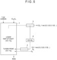
- Fig. 5 illustrates that the tuyere-injection CO gas is 1 mol when 1 mol of carbon is charged into the blast furnace 1.
- 1 mol of carbon charged in the blast furnace eventually turns into 1 mol (0.5 + 0.25 + 0.063 + 0.031 ...) of CO injected through the tuyere.
- 1 mol of CO generated beforehand and stored in the tank is injected through the tuyere.
- Y kmol of carbon is to be charged in the blast furnace, Y kmol of CO is injected from the tank through the tuyere.
- the breakdown of the calculation is 94.05Y ⁇ 10 3 kcal + 9.24Y ⁇ 10 3 kcal.
- the tuyere-injection-CO-gas operation in which all of the blast furnace gas from which CO 2 has been removed is injected through the blast furnace tuyere, it is necessary to solely inject oxygen to prevent N 2 from accumulating in the blast furnace. In such an operation, N 2 is not present in the tuyere-front raceway and the gas volume in the tuyere-front raceway is reduced. It is thus expectable that the tuyere-front raceway temperature Tf will increase. In the normal operation, the tuyere-front raceway temperature Tf is approximately 2,100 degrees C.
- the gas discharged from the tuyere-front raceway does not contain N 2 , and thus it has a smaller volume than that in the normal operation, resulting in an excessively large heat flow ratio.
- the tuyere-front raceway temperature Tf and the volume of the gas discharged from the tuyere-front raceway during the tuyere-injection-CO-gas operation will thus be calculated below.
- the breakdown of the calculation is 2 ⁇ 0.866 kmol ⁇ 110.5 kJ/mol ⁇ 0.239 cal/J ⁇ 10 3 .
- Oxygen injected into the tuyere is calculated based on the oxygen balance, based on which the amount of combusted C is calculated.
- 27.27 kg is an amount of oxygen taken away from the iron ore as described above.
- the amount of CO generated is 2 ⁇ 0.866 kmol.
- the breakdown of the calculation is 2 ⁇ 0.866 kmol ⁇ 6 cal/kmol ⁇ (3,000 degrees C ⁇ 0.75).
- the amount of C combusted by oxygen injected into the tuyere (0.866 kmol) is 2 ⁇ 0.866 kmol.
- 6 cal/kmol is a specific heat of carbon at 3,000 degrees C and the tuyere-front raceway temperature Tf is assumed to be 3,000 degrees C. Further, the temperature of carbon entering the tuyere-front raceway is assumed to be 0.75 times as high as the tuyere-front raceway temperature Tf.
- the breakdown of the calculation is 45.74 ⁇ 10 3 kcal + 23.38 ⁇ 10 3 kcal + 15.87 ⁇ 10 3 kcal.
- the amount of CO discharged from the raceway is 96.6 kg.
- the injection amount of CO gas delivered via the tuyere-injection gas relay tank 4 is Y kmol.
- Y kmol which is equal to 1.718 kmol, is 48.10 kg.
- the heat input is 84.99 ⁇ 10 3 kcal (see (7-4) above).
- the heat output is 96.6 kg ⁇ 0.297 kcal/kg ⁇ Tf. 0.297 kcal/kg is a specific heat of CO at 3,000 degrees C.
- the blast furnace operation method in which all of the CO gas is injected through the tuyere, does not involve injection of N 2 into the tuyere, so that the tuyere-front raceway temperature Tf becomes as high as 2,962 degrees C.
- the temperature which is greatly different from that in the normal operation, causes damage to the refractory and tuyere, making it impossible to perform the oxygen injection and the operation for circulating all of the blast furnace gas.
- CO discharged from the raceway is 77.3 Nm 3 as described above, which is smaller than that in the normal operation (121 Nm 3 ).
- Fig. 1 is a conceptual diagram of a blast furnace operation method involving injection of the circulating N 2 gas together with the CO 2 -removed blast furnace gas through the tuyere of the blast furnace 1.
- the circulating N 2 gas is injected through the tuyere. 50% of the CO gas in the blast furnace turns into CO 2 whereas the rest (50%) of the CO gas stays unreacted, where the CO 2 -removed CO is repeatedly injected through the tuyere to be totally turned into CO 2 in the end.
- N 2 does not cause chemical reaction in the blast furnace, and only circulates within a circulation system of the blast furnace gas, that is, from the inside of the furnace to the furnace top and from the furnace top to the tuyere. It is only necessary that a predetermined amount of N 2 is contained in the blast furnace gas at the start of the operation. Unlike the blast delivered through the tuyere, N 2 is not continuously fed from the outside. N 2 does not burn in the tuyere-front raceway, and serves as a coolant for the tuyere-front raceway whose temperature is increased to a high temperature (2,962 degrees C) by O 2 injected through the tuyere, thereby keeping the Tf at 2,100 degrees C as in the base operation. Further, N 2 injected into the tuyere-front raceway allows the amount of gas generated in the tuyere-front raceway to be at the same level as that in the normal operation.
- Fig. 4 illustrates a flow of a blast furnace operation method in which the circulating N 2 is injected together with the CO 2 -removed blast furnace gas through the tuyere of the blast furnace 1.
- the flow illustrates a case where the same amount (63.62 kg) of iron as that in the base operation is produced.
- the circulating N 2 is stored in the tuyere-injection gas relay tank 4 together with the CO 2 -removed CO gas.
- N 2 and CO gases discharged from the tuyere-injection gas relay tank 4 are heated by the existing hot-blast stove 2 to 1,000 degrees C to 1,200 degrees C, and then injected through the blast furnace tuyere into the blast furnace 1.
- the heating of N 2 and CO gases by the hot-blast stove 2 is intended to reduce the amount of charged carbon for the purpose of reduction CO 2 discharge.
- the heating temperature may be determined in accordance with the amount of the circulating N 2 and a target Tf.
- the blast furnace operation method in which N 2 circulates together with the tuyere-injection CO gas, will be described below on the premise that the same amount (63.62 kg) of iron as that in the base operation is to be produced. It is assumed that the charged carbon in the blast furnace 1 is Y kmol.
- the breakdown of the calculation is Y ⁇ 393.5 kJ/mol ⁇ 0.239 Cal/J ⁇ 10 3 (see (6-1) above).
- the sensible heat of the tuyere-injection CO gas is 9.24Y ⁇ 10 3 kcal.
- N 2 circulating in the circulation system of the blast furnace gas is W kmol.
- This N 2 is fed to the blast furnace gas circulation system at the start of the blast furnace operation, and is not discharged out of the circulation system.
- a predetermined amount of N 2 may be circulated within the blast furnace. 28 kg is a molecular weight (kg/kmol) of N 2 and 0.272 kcal/kg is a specific heat of N 2 at 1,200 degrees C.
- the injected oxygen is never heated for the sake of security, and thus the injected oxygen has no sensible heat.
- the breakdown of the calculation is 94.05Y ⁇ 10 3 kcal + 9.24Y ⁇ 10 3 kcal + 9.14W ⁇ 10 3 kcal.
- the tuyere-front raceway temperature becomes high due to the absence of N 2 .
- Fine powdered coal is often injected in the normal blast furnace operation, where the tuyere-front raceway temperature Tf is set in a range from 2,000 degrees C to 2,400 degrees C.
- the target value of the tuyere-front raceway temperature Tf is set at 2,100 degrees C, and W kmol of nitrogen is injected as a coolant gas.
- the breakdown of the calculation is (Y - 27.27/32) ⁇ 2 ⁇ 110.5 kJ/mol ⁇ 0.239 cal/J.
- the oxygen injected into the tuyere-front raceway is obtained by subtracting 27.27 kg of oxygen taken away from the ore from 32Y kg of oxygen contained in the furnace top gas, which is (32Y - 27.27) kg equal to (Y - 27.27/32) kmol.
- the breakdown of the calculation is (Y - 27.27/32) ⁇ 2 kmol ⁇ 6 cal/mol ⁇ 2,100 degrees C ⁇ 0.75.
- ⁇ 2 kmol is an amount of carbon entering the tuyere-front raceway.
- 6 cal/kmol is a specific heat of carbon at 2,100 degrees C and the temperature of carbon entering the tuyere-front raceway is assumed to be 0.75 times as high as the tuyere-front temperature.
- the breakdown of the calculation is (52.82Y - 45.01) ⁇ 10 3 kcal + 9.24Y ⁇ 10 3 kcal + 9.14W ⁇ 10 3 kcal + (18.9Y - 16.12) ⁇ 10 3 kcal.
- An amount Y of carbon charge and an amount W of circulating N 2 are determined so that the tuyere-front raceway temperature Tf reaches 2,100 degrees C.
- the breakdown of the calculation is ((Y - 27.27/32) ⁇ 2 + Y) ⁇ 28 kg ⁇ 0.289 kcal/kg ⁇ 2,100 degrees C.
- 0.289 kcal/kg is a specific heat of CO at 2,100 degrees C.
- N 2 is heated by 16.82W ⁇ 10 3 kcal.
- the breakdown of the calculation is W kmol ⁇ 28 kg ⁇ 0.286 kcal/kg ⁇ 2,100 degrees C.
- 0.286 kcal/kg is a specific heat of N 2 at 2,100 degrees C.
- a total gas volume of CO and N 2 is 108.2 Nm 3 .
- the tuyere-front raceway temperature Tf is 2,100 degrees C and the gas volume in the tuyere-front raceway is 108.2 Nm 3 .
- the gas volume in the tuyere-front raceway is smaller than the gas volume 121 Nm 3 during the base operation.
- a small volume of the gas generated in the tuyere-front raceway makes the heat flow ratio large, which may cause a situation where heat transfer from the in-furnace gas to the charge is insufficient.
- the heat balance and the tuyere-front raceway temperature Tf when the value of the heat input in Inventive Example 1 (177.5 ⁇ 10 3 kcal) is gradually increased by increasing the charged carbon are calculated.
- a total gas volume of CO and N 2 is 122 Nm 3 .
- the breakdown of the calculation is Y ⁇ 393.5 kJ/mol ⁇ 0.239 Cal/J ⁇ 10 3 kcal (see (6-1) above).
- the breakdown of the calculation is (Z ⁇ 2 kg ⁇ 3.572 kcal/kg ⁇ 1,200 degrees C). 3.572 kcal/kg is a specific heat of hydrogen at 1,200 degrees C.
- the breakdown of the calculation is 94.05Y ⁇ 10 3 kcal + 9.24Y ⁇ 10 3 kcal + 57.79Z ⁇ 10 3 kcal + 8.573Z ⁇ 10 3 kcal.
- the tuyere-front raceway temperature becomes high due to the absence of N 2 .
- the target value of the tuyere-front raceway temperature Tf is set at 2,100 degrees C, and Z kmol of hydrogen is injected through the tuyere as a coolant gas.
- the breakdown of the calculation is (Y + 0.5Z - 27.27/32) ⁇ 2 ⁇ 110.5 kJ/mol ⁇ 0.239 cal/J ⁇ 10 3 kcal.
- 27.27 kg is an amount of oxygen taken away from the ore.
- the breakdown of the calculation is (Y + 0.5Z - 27.27/32) ⁇ 2 kmol ⁇ 6 cal/mol ⁇ 2,100 degrees C ⁇ 0.75.
- the breakdown of the calculation is (52.82Y + 26.41Z - 45.01) ⁇ 10 3 kcal + (18.9Y + 9.45Z - 16.11) ⁇ 10 3 kcal + 9.24Y ⁇ 10 3 kcal + 8.573Z ⁇ 10 3 kcal.
- Heat output Hydrogen is added so that the tuyere-front raceway temperature reaches 2,100 degrees C.
- the breakdown of the calculation is ((Y + 0.5Z - 27.27/32) ⁇ 2 + Y) kmol ⁇ 28 kg ⁇ 0.289 kcal/kg ⁇ 2,100 degrees C.
- (Y + 0.5Z - 27.27/32) ⁇ 2 kmol is a molar quantity of CO generated in front of the tuyere
- Y is a molar quantity of CO injected through the tuyere
- 28 is a molecular weight of CO
- 0.289 kcal/kg is a specific heat of CO at 2,100 degrees C.
- Z + Z is an amount of initially injected hydrogen and hydrogen injected through the tuyere via the relay tank, and 3.764 kcal/kg is a specific heat of H 2 at 2,100 degrees C.
- the breakdown of the calculation is (50.98Y + 17.00Z - 28.97) ⁇ 10 3 kcal + 31.62Z ⁇ 10 3 kcal.
- the gas volume in the tuyere-front raceway is 97 Nm 3 , which is smaller than 121 Nm 3 in the base operation.
- circulating N 2 is added to the tuyere-injection CO gas and H 2 to increase the gas volume in the tuyere-front raceway.
- the entire heat balance of the blast furnace 1 and the tuyere-front raceway Tf are calculated by changing the addition amount of N 2 .
- the breakdown of the calculation is Y ⁇ 393.5 kJ/mol ⁇ 0.239 Cal/J ⁇ 10 3 kcal (see (6-1) above).
- the breakdown of the calculation is Z ⁇ 241.8 kJ/mol ⁇ 0.239 kcal/kJ ⁇ 10 3 kcal (see (11-3) above).
- W 1 kmol is assigned to 9.14W ⁇ 10 3 kcal (see (8-3) above).
- the breakdown of the calculation is 94.05Y ⁇ 10 3 kcal + 9.24Y ⁇ 10 3 kcal + 57.79Z ⁇ 10 3 kcal + 8.573Z ⁇ 10 3 kcal + 9.14 ⁇ 10 3 kcal.
- the production is the same as that (63.62 kg) in the base operation.
- the heat requirement increases to prevent a decrease in the tuyere-front raceway temperature, and thus the charged carbon Y is slightly increased.
- the heat requirement of a formula (A′′′) matching the above formula (B) defining the tuyere-front raceway temperature is 200 ⁇ 10 3 kcal.
- 103 .3Y + 66 .36Z + 9 .14 ⁇ 10 3 kcal 200 ⁇ 10 3 kcal
- the breakdown of the calculation is (Y + 0.5Z - 27.27/32) ⁇ 2 ⁇ 110.5 kJ/mol ⁇ 0.239 cal/J ⁇ 10 3 kcal (see (12-1) above).
- W 1 kmol is assigned to 9.14W ⁇ 10 3 kcal (see (8-3) above).
- the breakdown of the calculation is (52.82Y + 26.41Z - 45.01) ⁇ 10 3 kcal + (18.9Y + 9.45Z - 16.11) ⁇ 10 3 kcal + 9.24Y ⁇ 10 3 kcal + 8.573Z ⁇ 10 3 kcal + 9.14 ⁇ 10 3 kcal.
- (16-1) CO is heated by (50.98Y + 17.00Z - 28.97) ⁇ 10 3 kcal (see (13-1) above).
- N 2 is heated by 16.82 ⁇ 10 3 kcal.
- W 1 kmol is assigned to 16.82W ⁇ 10 3 kcal (see 10-2 above).
- Fig. 6 illustrates a blast furnace operation method involving injection of a part of CO 2 -removed blast furnace gas through the tuyere of the blast furnace 1.
- Some of iron ores to be used in the blast furnace 1 contain, for instance, impurities such as Zn and Pb.
- impurities such as Zn and Pb.
- the impurities are not blown out sufficiently at the start of operation after the non-operation period, or some of the impurities may be required to be constantly blown out. In such a case, a part of the blast furnace gas may be blown out into a blast furnace gas holder 5.
- the above-described operation involving blowing a part of the blast furnace gas out of the furnace is usable as an intermediate step between the base operation and the operation involving injection of all of the blast furnace gas through the tuyere.
- a part of the circulating N 2 gas is blown out together with the blast furnace gas to be blown out. It is thus necessary to supplement the circulating N 2 gas to compensate for the N 2 gas blown out.
- the circulating N 2 gas is optionally supplemented using the blast.
- a part of CO gas and N 2 gas is injected through the tuyere in the operation illustrated in Fig. 6
- a part of the blast furnace gas containing CO gas, H 2 gas, and N 2 gas is optionally injected through the tuyere in the operation.
- CO 2 gas is circulated as in N 2 gas circulation to increase the gas volume in the tuyere front, preventing the increase in the tuyere-front raceway temperature Tf and the reduction in gas volume in the tuyere-front raceway.
- Fig. 7 illustrates an exemplary blast furnace operation method of circulating a part of CO 2 gas in the blast furnace.
- O 2 gas is injected through the tuyere, CO 2 is separated and removed from a part of the blast furnace gas discharged from the blast furnace top, and all of the CO 2 -removed CO gas is injected together with the rest of the blast furnace gas not separating and removing CO 2 from the blast furnace gas discharged from the blast furnace top through the blast furnace tuyere.
- CO + CO 2 the blast furnace gas
- CO 2 is separated and removed by a CCS 3 (Carbon dioxide Capture and Storage).
- the rest of the blast furnace gas is stored in the tuyere-injection gas relay tank 4 without passing through the CCS 3.
- CO 2 and CO gas discharged from the tuyere-injection gas relay tank 4 are heated by the existing hot-blast stove 2 to 1,000 degrees C to 1,200 degrees C and then injected through the blast furnace tuyere into the blast furnace 1.
- the heating of CO 2 and CO gases by the hot-blast stove 2 is intended to reduce the amount of charged carbon for the purpose of reduction CO 2 discharge.
- the gas relay tank 4 stores all of the CO gas contained in the furnace top gas. Since the furnace top gas without passing through the CCS 3 is mixed thereinto, a certain amount of CO 2 is contained in the gas in the gas relay tank 4.
- the tuyere-front raceway temperature Tf and the gas volume in the tuyere-front raceway are kept substantially at the same level as those in the base operation, making it possible to reduce the charged carbon and consequently the CO 2 discharge from the blast furnace.
- the blast furnace operation method in which CO 2 gas circulates together with the tuyere-injection CO gas, will be described below on the premise that the same amount (63.62 kg) of iron as that in the base operation is to be produced. It is assumed that the charged carbon in the blast furnace 1 is Y kmol.
- the breakdown of the calculation is Y ⁇ 393.5 kJ/mol ⁇ 0.239 Cal/J ⁇ 10 3 (see (6-1) above).
- CO 2 circulating in the circulation system of the blast furnace gas is W kmol. 44 kg is a molecular weight (kg/kmol) of CO 2 and 0.277 kcal/kg is a specific heat of CO 2 at 1,200 degrees C.
- the breakdown of the calculation is 94.05Y ⁇ 10 3 kcal + 9.24Y ⁇ 10 3 kcal + 14.63W ⁇ 10 3 kcal.
- the breakdown of the calculation is (Y - 27.27/32) ⁇ 2 ⁇ 110.5 kJ/mol ⁇ 0.239 cal/J (see (9-1) above).
- the breakdown of the calculation is W kmol ⁇ 44 kg ⁇ 0.277 ⁇ 1,200 degrees C.
- CO 2 reacts chemically with C in front of the tuyere, as follows.
- the reaction heat for W kmol is 172.5 kJ/kmol ⁇ 0.239 cal/J ⁇ 10 3 kcal.
- the heat capacity of C combusted by oxygen is (18.9Y - 16.12) ⁇ 10 3 kcal (see (9-4) above). Further, the heat capacity of C that reacts with CO 2 in front of the tuyere is 9.45W ⁇ 10 3 kcal.
- the reaction heat of 1 kmol of CO 2 which reacts with 1 kmol of C, is W kmol ⁇ 6 cal/mol ⁇ 2,100 degrees C ⁇ 0.75 (see (9-4) above).
- An amount Y of carbon charge and an amount W of circulating CO 2 are determined so that the tuyere-front raceway temperature Tf reaches 2,100 degrees C.
- the breakdown of the calculation is ((Y - 27.27/32) ⁇ 2 + Y) ⁇ 28 kg ⁇ 0.289 kcal/kg ⁇ 2,100 degrees C (see (10-1) above).
- the breakdown of the calculation is 2W kmol ⁇ 28 kg ⁇ 0.289 kcal/kg ⁇ 2,100 degrees C.
- a total gas volume is 89.7 Nm 3 .
- the tuyere-front raceway temperature Tf is 2,100 degrees C and the gas volume in the tuyere-front raceway is 89.7 Nm 3 .
- the gas volume in the tuyere-front raceway is smaller than the gas volume 121 Nm 3 during the base operation.
- measures to make the gas volume in the tuyere-front raceway close to the gas volume (121 Nm 3 ) during the base operation will be studied in Inventive Example 5.
- the volume of the circulating CO 2 can be increased.
- the heat balance and the tuyere-front raceway temperature Tf when the value of the heat input in Inventive Example 4 (177.5 ⁇ 10 3 kcal) is gradually increased by increasing the charged carbon are calculated.
- the gas volume is calculated as described below based on a formula (C'), in which the amount of heat input in the above formula (C) is changed to 215 ⁇ 10 3 kcal, and the formula (D), the gas volume in the tuyere-front raceway is 121 Nm 3 .
- a total gas volume is 121 Nm 3 .
- Fig. 8 illustrates a blast furnace operation method involving injection of a part of the CO 2 -removed CO gas and a part of the blast furnace gas through the blast furnace tuyere.
- the significance of the above blast furnace operation method is the same as that of the blast furnace operation involving injection of a part of CO gas and N 2 gas through the tuyere (see the description for the blast furnace operation method illustrated in Fig. 6 ).
- Fig. 8 illustrates a flow of blowing ⁇ kmol of CO gas, from which CO 2 gas is removed by the CCS 3, into the blast furnace gas holder 5.
- a collected amount of CO 2 is (Y - ⁇ ) kmol subtracting CO blown into the holder.
- CO 2 gas circulation is as useful as N 2 gas circulation.
- unused CO gas within the blast furnace gas can be fully (i.e. by 100%) used, making it possible to reduce the amount of the carbon used in the blast furnace by 16%.
- the CO 2 -removed CO gas contains H 2 gas, the amount of carbon used is further reducible and further reduction in CO 2 is expectable.
- pig iron can be produced with reduced CO 2 under substantially the same operation conditions as those in existing large blast furnaces.
Landscapes
- Engineering & Computer Science (AREA)
- Chemical & Material Sciences (AREA)
- Manufacturing & Machinery (AREA)
- Materials Engineering (AREA)
- Metallurgy (AREA)
- Organic Chemistry (AREA)
- Environmental & Geological Engineering (AREA)
- Mechanical Engineering (AREA)
- General Engineering & Computer Science (AREA)
- Manufacture Of Iron (AREA)
- Waste-Gas Treatment And Other Accessory Devices For Furnaces (AREA)
Abstract
Description
- The present invention relates to a blast furnace operation method.
- In order to restrain global warming caused by the increase in CO2 discharge, there is a strong demand for the reduction in CO2 discharge. The steel industry generates a large amount of CO2, and faces a serious problem of reducing the CO2 discharge. The main source of CO2 discharge from steel plants is blast furnaces. It is thus requested to reduce the CO2 discharge from the blast furnaces.
- There is a technique to inject a blast furnace gas into a blast furnace for the purpose of reducing the CO2 discharge from the blast furnace.
Patent Literature 1 discloses a blast furnace operation method, in which CO2 is separated and removed from at least a part of a blast furnace gas discharged from a blast furnace top, the blast furnace gas is heated to raise the temperature thereof and then is injected through a gas inlet A provided at a blast furnace shaft, and a preheat gas is injected into the furnace through a gas inlet B provided above the gas inlet A. -
Patent Literature 2 discloses a blast furnace operation method for addressing problems in an oxygen blast furnace, the problems including (1) a temperature Tf in front of the tuyere (hereinafter also referred to as "tuyere-front temperature Tf") becomes excessively high; and (2) a heat flow ratio becomes too large, reducing heat transfer to the charge. With regard to (1), CO2, H2O, or the like is injected through the tuyere to keep the tuyere-front temperature Tf in a range from 2,000 degrees C to 2,600 degrees C. With regard (2), a preheat gas is injected through an inlet at a middle section of the shaft. -
Patent Literature 3 discloses a blast furnace operation method including steps of: generating a steam reforming gas using steam and a thermally decomposed gas generated by thermal decomposition of waste plastics; generating a recycled methane gas using a blast furnace gas and hydrogen gas generated from the steam reforming gas; and injecting a blast gas and a reducing material through a tuyere of a blast furnace into the blast furnace, where the blast gas is oxygen gas and at least a part of the reducing material is the recycled methane gas. - Non-Patent
Literature 1 discloses a study on permeation of a furnace top gas injected into the blast furnace. -
- Patent Literature 1:
JP 2018-70952 A - Patent Literature 2:
JP S60-159104 A - Patent Literature 3:
JP 2021-152212 A - "On the Top Gas Recycled Reforming Process and the Injected Gas Distribution" by Nishio et al., Tetsu-to-Hagane, Vol. 59 (1973) No.12
- Various ideas have been proposed to inject a blast furnace gas into a blast furnace to reduce the CO2 discharge. In
Patent Literature 1 andNon-Patent Literature 1, the blast furnace gas is injected into the blast furnace from a lower part of a shaft. The blast furnace gas, however, does not sufficiently permeate into an inside of the furnace. The blast furnace gas is preferably injected through a tuyere of the blast furnace (hereinafter also referred to as "blast furnace tuyere" or simply "tuyere") in injecting the blast furnace gas into the blast furnace. - Further,
Patent Literature 2 describes the problems associated with an oxygen blast furnace in which the tuyere-front temperature Tf becomes excessively high and the heat flow ratio becomes excessively large due to the decrease in gas volume in front of the tuyere to make heat transfer to the charge insufficient. It is necessary to inject the preheat gas at the shaft to compensate for the heat flow ratio.Patent Literature 3 discloses that CO2 and CO gases in the blast furnace gas are transformed into CH4 by hydrogen and the CH4 is injected through a blast furnace tuyere. Injecting a large amount of CH4 decreases the temperature in front of the tuyere. In view of the above, injecting oxygen in place of hot blast (air) allows a large amount of CH4 to be injected without lowering the temperature in front of the tuyere. In other words, the blast furnace gas can be injected through the blast furnace tuyere. In this case, instead of using commercially available hydrogen, hydrogen is synthesized from waste plastics. - It should be noted that, when a reducing gas is injected through the blast furnace tuyere, attention should be paid to a change in gas volume in a raceway in front of the tuyere (hereinafter also referred to as "tuyere-front raceway") as well as prevention of a decrease in the temperature in front of the tuyere. This is because the change in the gas volume in the tuyere-front raceway results in a change in the gas volume inside the blast furnace, which changes the heat flow ratio (i.e. a ratio of a heat capacity of a solid to a heat capacity of a gas). There is also a problem of the production cost of hydrogen produced from the waste plastics.
- An object of the invention is to prevent, in a blast furnace operation involving injection of oxygen and a blast furnace gas (CO gas generated by removing CO2 from a furnace top gas) through a tuyere, an increase in a temperature Tf in a raceway in front of the tuyere (hereinafter also referred to as "tuyere-front raceway temperature Tf") and a decrease in gas volume at a lower part of the furnace, thereby reducing CO2 discharged from the blast furnace under operation conditions similar to those in a normal operation.
- The gist of the invention is as follows.
- (1) A blast furnace operation method including: injecting O2 gas through a tuyere of a blast furnace; separating and removing CO2 from a blast furnace gas discharged from a furnace top of the blast furnace; and injecting all of CO gas after removing CO2 through the tuyere of the blast furnace, in which all of N2 gas, which is injected through the tuyere of the blast furnace and discharged from the furnace top of the blast furnace together with the CO gas after removing CO2, is circulated within the blast furnace.
- (2) A blast furnace operation method including: injecting O2 gas through a tuyere of a blast furnace; separating and removing CO2 from a blast furnace gas discharged from a furnace top of the blast furnace; and injecting a part of CO gas after removing CO2 through the tuyere of the blast furnace, in which N2 gas, which is injected through the tuyere of the blast furnace and discharged through the furnace top of the blast furnace together with the part of the CO gas after removing CO2, is circulated within the blast furnace.
- (3) The blast furnace operation method according to (1) or (2), in which an H2 gas is injected through the tuyere of the blast furnace and the CO gas after removing CO2 contains the H2 gas.
- (4) A blast furnace operation method including: injecting O2 gas through a tuyere of a blast furnace; separating and removing CO2 from a part of a blast furnace gas discharged from a furnace top of the blast furnace to produce a CO gas; and injecting, through the tuyere of the blast furnace, all of the CO gas after removing CO2 together with a rest of the blast furnace gas not separating and removing CO2 from the blast furnace gas discharged from the furnace top of the blast furnace.
- (5) A blast furnace operation method including: injecting O2 gas through a tuyere of a blast furnace; separating and removing CO2 from a part of a blast furnace gas discharged from a furnace top of the blast furnace to produce a CO gas; and injecting, through the tuyere of the blast furnace, a part of the CO gas after removing CO2 together with a rest of the blast furnace gas not separating and removing CO2 from the blast furnace gas discharged from the furnace top of the blast furnace.
- (6) The blast furnace operation method according to (4) or (5), in which an H2 gas is injected through the tuyere of the blast furnace and the CO gas after removing CO2 contains the H2 gas.
- In the following, "injecting N2 gas through the tuyere of the blast furnace together with CO2-removed CO gas (i.e. CO gas after removing CO2 from the blast furnace gas) and circulating the N2 gas discharged from the furnace top within the blast furnace" will be occasionally referred to as "N2 gas circulation". Further, "injecting, through the tuyere of the blast furnace, all of the CO2-removed CO gas together with the rest of the blast furnace gas not separating and removing CO2 from the blast furnace gas" will be occasionally referred to as "CO2 gas circulation".
- The invention relates to a blast furnace operation method in which all of the CO gas obtained by separating and removing CO2 from the blast furnace gas is injected through the blast furnace tuyere. CO2 can be removed from the furnace top gas using CCS (CO2 capture and storage) technique. However, the blast furnace gas still contains a large amount of N2 only by removing CO2. Thus, when all of such a blast furnace gas is injected through the tuyere, N2 accumulates in the blast furnace, making it difficult to continue the blast furnace operation. In order to prevent the N2 accumulation, it is necessary to inject oxygen in place of air through the tuyere. However, when oxygen is solely injected, the gas volume generated in the tuyere-front raceway decreases due to the absence of N2, which changes the heat flow ratio and increases the tuyere-front raceway temperature Tf, thereby making it difficult to perform the blast furnace operation.
- The invention is made to solve the above problems.
- (1) In a blast furnace operation in which O2 gas and all of the CO2-removed CO gas are injected through the blast furnace tuyere, the tuyere-front raceway temperature Tf becomes too high to perform the blast furnace operation. By employing the N2 gas circulation or CO2 gas circulation together with the CO gas, the tuyere-front raceway temperature Tf can be set at the same level as that in the normal operation.
- (2) When the amount of gas generated in the tuyere-front raceway of the blast furnace greatly changes from that in the normal operation of existing large blast furnaces, it is difficult to perform the blast furnace operation. By employing the N2 gas circulation or CO2 gas circulation, the amount of gas generated in the tuyere-front raceway can be set substantially at the same level as that in the normal operation.
- (3) N2 gas circulation or CO2 gas circulation according to the invention is capable of maintaining the heat flow ratio and the tuyere-front raceway temperature Tf that are the substantially the same as those of a base operation (normal operation), making it possible to reduce the discharge of CO2 gas with existing blast furnace operation techniques.
-
-
Fig. 1 is a conceptual diagram illustrating a blast furnace operation method using N2 gas circulation. -
Fig. 2 illustrates a base operation. -
Fig. 3 illustrates a flow of a blast furnace operation method including injection of CO2-removed CO gas through a blast furnace tuyere without N2 gas circulation. -
Fig. 4 illustrates a flow of a blast furnace operation method using N2 gas circulation. -
Fig. 5 illustrates that CO gas injected through the blast furnace tuyere is 1 mol when 1 mol of carbon is charged into a blast furnace. -
Fig. 6 illustrates that a part of the CO2-removed CO gas or a part of H2 gas is injected through the blast furnace tuyere. -
Fig. 7 illustrates CO2 gas circulation where all of the CO2-removed CO gas and a part of a blast furnace gas discharged from a furnace top are injected through the blast furnace tuyere. -
Fig. 8 illustrates CO2 gas circulation where a part of the CO2-removed CO gas and a part of the blast furnace gas discharged from the furnace top are injected through the blast furnace tuyere. - There is a demand for the reduction in discharge of carbon dioxide to prevent global warming. In the steel industry, a
blast furnace 1 is equipment that mainly discharges carbon dioxide. N2 gas circulation or CO2 gas circulation according to the invention is capable of maintaining a heat flow ratio and a raceway temperature in front of a tuyere Tf (hereinafter also referred to as a tuyere-front raceway temperature Tf) that are the substantially the same as those of a base operation (normal operation), making it possible to reduce the discharge of CO2 gas with existing blast furnace operation techniques. - First, a base operation will be described. The base operation refers to a blast furnace operation having been usually carried out since before the filing of the invention. Premises of the base operation are as follows.
- (1-1) For easy understanding of the description, it is assumed that the
blast furnace 1 is in all-coke operation, where a blast volume per unit time is 100 Nm3 (N2: 79 Nm3, O2: 21 Nm3) and a blast temperature is 1,000 degrees C. - (1-2) It is assumed that an indirect reduction rate and a direct reduction rate in the blast furnace are 70% and 30%, respectively.
- (1-3) It is assumed that a gas utilization efficiency (ηCO) in the blast furnace is 50%.
- (1-4) It is assumed that ore to be charged is totally composed of Fe2O3.
- (1-5) Although a part of charged carbon enters into pig iron, such carbon is not directly involved in reactions in the blast furnace. The following description will thus be made on iron containing no carbon.
-
Fig. 2 illustrates an in-furnace status of theblast furnace 1 in the base operation. - The blast volume is 100 Nm3, in which N2 accounts for 79 Nm3 and O2 accounts for 21 Nm3. In a gas composition in a raceway in front of a tuyere, N2 stays unreacted whereas O2 is transformed into 42Nm3 of CO by a reaction of C + O2 → 2CO.
- The composition in a lower part of the shaft is as follows. It is assumed that a part of charged carbon is transformed into X Nm3 of CO by a reaction of FeO + C → Fe + CO, which is a direct reduction. The X Nm3 of CO generated by direct reduction is combined with 42 Nm3 of CO in front of the tuyere to contribute to indirect reduction. Since the gas utilization efficiency is 50%, a half of CO generated in a lower part of the furnace contributes to the indirect reduction. The direct reduction rate is 30% as premised, establishing the following equation.

- In the above, the numerator is an amount of oxygen consumed by the direct reduction. The denominator is a sum of the oxygen consumed by the direct reduction and the oxygen consumed by the indirect reduction, which is a half (gas utilization efficiency: 50%) of a sum of CO generated in front of the tuyere and CO (X) generated by the direct reduction. From this formula, X = 11.45 is satisfied, and the volume of CO at the lower part of the shaft is 42 + 11.45 = 53.45 Nm3.
- The composition of a furnace top gas is as follows. The utilization efficiency of a blast furnace gas (ηCO) is 50%. Accordingly, the 53.45 Nm3 of CO generated at the lower part of the shaft turns into 26.73 Nm3 of CO2 and 26.73 Nm3 of CO in the furnace top gas.
- All of the charged carbon turns into CO or CO2 contained in the furnace top gas. Accordingly, the amount of charged carbon is 53.45/22.4 = 2.386 mol, which is 2.386 × 12 = 28.63 kg.
- The yield of iron can be calculated based on an oxygen balance. Oxygen from the blast is 21 Nm3/22.4 × 32 kg = 30 kg. Oxygen contained in the furnace top gas is 26.73 Nm3/22.4 × 16 kg + 26.73 Nm3/22.4 × 32 kg = 57.27 kg. Oxygen taken away from iron ore is 57.27 - 30 = 27.27 kg. Accordingly, the yield of iron is 27.27 × 112/48 = 63.62 kg. In the above, 112/48 is a ratio between iron and oxygen in Fe2O3 (56 × 2/16 × 3).
- Assuming that carbon in pig iron is 4.5%, a yield of the pig iron is 63.62/0.955 = 66.62 kg.
- Assuming that carbon in coke is 90%, the volume of charged coke is 28.63/0.9 = 31.81 kg. 28.63 is an amount of the charged carbon. As described above, all of the charged carbon turns into CO or CO2 contained in the furnace top gas. Accordingly, the amount of charged carbon is 53.45/22.4 = 2.386 mol, which is 2.386 × 12 = 28.63 kg.
- A ratio of coke is 31.81 kg/66.62 kg = 477 kg/tpig.
- Next, a heat input during the base operation is calculated below.
- In
Fig. 2 , the source of heat input to theblast furnace 1 is charged carbon and sensible heat of blast heated by a hot-blast stove 2. The charged carbon is reacted to be oxidized with oxygen in the blast furnace, turns into CO2 and CO, and is discharged as the furnace top gas. Combustion heat of C is formation heat of CO2 and CO. Thus, the heat input to theblast furnace 1 is a sum of the formation heat of CO2 and CO in the furnace top gas and the sensible heat of blast. - (2-1) The amount of the heat input generated by the reaction of the charged carbon to CO2 is, considering that a half (1.193 kmol) of the charged carbon (2.386 kmol) turns into CO2 in
Fig. 2 , 1.193 kmol × 393.5 kJ/mol × 0.239 cal/J × 103 = 112.2 × 10³ kcal. As described in "Basic Chemistry" 21nd edition (Shokabo Co., Ltd.), p.132, a standard formation heat of gas in an oxidation process of C into CO2 (C + O2 = CO2) is ΔH = -393.5 kJ/mol. - (2-2) The amount of the heat input generated by reaction of the charged carbon to CO is, considering that a half (1.193 kmol) of the charged carbon (2.386 kmol) turns into CO in
Fig. 2 , 1.193 kmol × 110.5 kJ/mol × 0.239 cal/J × 103 = 31.51 × 10³ kcal. The formation heat of CO gas is ΔH = -110.5 kJ/mol. - (2-3) The temperature of blast is 1,000 degrees C. The sensible heat of blast, in which the N2 component accounts for 26.37 × 10³ kcal and the O2 component accounts for 7.41 × 10³ kcal, is 33.78 × 10³ kcal in total. The sensible heat of N2 (26.37 × 10³ kcal) is calculated by (79 Nm3/22.4) × 28 kg × 0.267 cal/kg. The sensible heat of O2 (7.41×10³ kcal) is calculated by (21 Nm3/22.4) × 32 kg × 0.247 cal/kg. Specific heats of N2 and O2 at 1,000 degrees C are 0.267 cal/kg and 0.247 cal/kg, respectively.
- (2-4) The heat input is 177.5 × 10³ kcal in total (breakdown: 112.2 × 10³ kcal + 31.5 × 10³ kcal + 33.78 × 10³ kcal).
- As illustrated in
Fig. 2 , a heat amount of 177.5 × 10³ kcal is needed to produce 63.62 kg of iron. This heat includes a reduction heat of iron, heat transferred to pig iron and slag, heat diffused from a furnace body, and the like. The breakdown is reduction heat of iron (67.6%), sensible heat of hot metal or slag (17.2%), sensible heat of furnace top gas (6.2%), lost heat in furnace body, and the like ("Manufacture of Pig Iron/Steel" (Asakura Publishing Co., Ltd.), p.22). - (3-1) Sensible heat of blast: 33.78 × 10³ kcal (see (2-3) above)
- (3-2) Carbon combustion heat: 49.53 × 10³ kcal (1.875 kmol × 110.5 kJ/mol × 0.239 Cal/J)
- (3-3) Heat capacity of carbon entering tuyere-front raceway: 20.25 × 10³ kcal
- Assuming that the tuyere-front raceway temperature is 2,400 degrees C, the temperature of carbon entering the tuyere-front raceway is 0.75 times as high as the tuyere-front raceway temperature, and the specific heat of carbon at 2,400 degrees C is 6 cal/kmol, the above heat capacity is calculated by as follows: (42/22.4) kmol × 6 cal/kmol × (2400 degrees C × 0.75) = 20.25 × 10³kcal.
- (3-4) Sum of heat input to the tuyere-front raceway: 103.6 × 10³ kcal
- (4-1) Gas Volume in Raceway
- Heat capacity of 79 Nm3 of N2 : 79/22.4 × 28 × 0.29 × Tf = 28.64Tf
- Heat capacity of 42 Nm3 of CO: 42/22.4 × 28 × 0.292 × Tf = 15.33Tf
- In the above, 28 is a molecular weight of each of N2 and CO, and 0.29 and 0.292 are specific heats of N2 and CO assuming that Tf is 2,300 degrees C.
- (4-2) Raceway Temperature Tf
-

- Tf = 2,356 degrees C is obtained by the above formula.
- (4-3) The tuyere-front raceway temperature reaches as high as 2,356 degrees C in an in all-coke operation. However, it is believed that the tuyere-front raceway temperature reaches approximately 2,100 degrees C by injecting fine powdered coal in an actual operation.
- In this blast furnace operation method, O2 is injected through the tuyere of the
blast furnace 1, CO2 is separated and removed from the blast furnace gas discharged from the blast furnace top, and all of the CO2-removed CO gas is injected through the blast furnace tuyere without N2 gas circulation (Fig. 3 ). - In the following, the CO gas injected through the blast furnace tuyere will be occasionally referred to as a "tuyere-injection CO gas". After CO2 is removed by a carbon dioxide capture and storage (CCS), all of the CO gas not contributing to reduction of ore is injected again through the tuyere. The tuyere-injection CO gas, which is discharged from the furnace top and entirely and repeatedly injected through the tuyere, totally turns into CO2 to contribute to reduction of iron ore. This reduces the coke ratio and reduction in CO2 is expectable.
- (5-1) In a normal blast furnace operation, air is injected through the tuyere to combust the coke in the furnace. The blast furnace gas thus contains nitrogen. It should be noted that the blast furnace gas is not discharged to the outside in the blast furnace operation in which all of the CO2-removed blast furnace gas is injected through the blast furnace tuyere. In such an operation, if air is injected through the tuyere, N2 is continuously delivered into the blast furnace to accumulate therein. In view of the above, in the blast furnace operation involving injection of all of the CO2-removed blast furnace gas through the blast furnace tuyere, it is premised that O2 without N2 is injected, instead of air, during the operation.
- (5-2) In the blast furnace operation, in which oxygen and all of the CO2-removed CO gas are injected through the blast furnace tuyere, N2 is not injected through the tuyere and the gas volume in the tuyere-front raceway is small, making the tuyere-front raceway temperature Tf high. An excessively high Tf makes it difficult to perform the blast furnace operation. It is thus necessary to keep the tuyere-front raceway temperature Tf at the same level as that in the normal operation.
- (5-3) In the blast furnace operation in which all of the CO2-removed CO gas is injected through the blast furnace tuyere, N2 is not injected through the tuyere and the gas volume in the tuyere-front raceway is smaller than that in an operation in a current large blast furnace. This makes the heat flow ratio (a ratio between a heat capacity of a solid and a heat capacity of a gas) large and heat transfer from an in-furnace gas to the charge decreases, resulting in a difficulty in the blast furnace operation. It is necessary to keep the gas volume in the tuyere-front raceway at the same level as that in the normal operation.
- In an operation illustrated in
Fig. 3 , the yield of iron is the same as that in the base operation (63.62 kg), where all of CO obtained by removing CO2 from the furnace top gas is stored in a tuyere-injectiongas relay tank 4, is heated to 1,200 degrees C in the hot-blast stove 2, and is injected into the blast furnace through the blast furnace tuyere. - It is assumed that an amount of carbon needed to produce 63.62 kg of iron (the same amount as in the base operation) is Y kmol.
- (6-1) Heat input generated by combusting C (C to CO2) is 94.05Y × 103 kcal. This is the formation heat of CO2, that is, the heat generated when C combusted in the blast furnace turns into CO2, (breakdown of the calculation: Y × 393.5 kJ/mol × 0.239 Cal/J × 103). CO gas is repeatedly injected through the tuyere to turn into CO2. Thus, all of the charged carbon turns into CO2. As described in "Basic Chemistry" 21nd edition (Shokabo Co., Ltd.), p.132, a standard formation heat of gas in an oxidation process of C into CO2 (C + O2 = CO2) is ΔH = -393.5 kJ/mol. Further, 1 J = 0.239 cal is satisfied.
- (6-2) The sensible heat of the tuyere-injection CO gas is 9.24Y × 103 kcal.
- The breakdown of the calculation is (Y × 28 kg × 0.275 kcal/kg × 1,200 degrees C). The amount of the tuyere-injection CO gas is Y kmol (described below). The CO gas is heated to 1,200 degrees C. 28 kg is a molecular weight (kg/kmol) of CO and 0.275 kcal/kg is a specific heat of CO at 1,200 degrees C.
- The amount of the tuyere-injection CO gas will be described below. When the charged carbon into the blast furnace is Y kmol, the injection amount of CO gas delivered via the tuyere-injection
gas relay tank 4 is Y kmol. It is premised that the CO gas utilization efficiency ηCO is 50%. Thus, 0.5Y kmol of CO2 is produced from Y kmol of the charged carbon and 0.5Y kmol of CO2 is produced from Y kmol of the tuyere-injection CO gas, resulting in Y kmol of CO2 in total. -
Fig. 5 illustrates that the tuyere-injection CO gas is 1 mol when 1 mol of carbon is charged into theblast furnace 1. - When 1 mol of carbon is charged into the
blast furnace 1, assuming that the indirect reduction rate is 50%, a furnace top gas that contains (1) 0.5 mol of CO2 and 0.5 mol CO is produced. Subsequently, when 0.5 mol of CO, (1) above, is injected through the tuyere via the tuyere-injection COgas relay tank 4, the furnace top gas that contains (2) 0.25 mol of CO2 and 0.25 mol of CO is produced. When 0.25 mol of CO, (2) above, is injected through the tuyere, the furnace top gas that contains (3) 0.125 mol of CO2 and 0.125 mol of CO is produced. Similarly, 0.063 mol, 0.031 mol, ... of CO is repeatedly injected through the tuyere. 1 mol of carbon charged in the blast furnace eventually turns into 1 mol (0.5 + 0.25 + 0.063 + 0.031 ...) of CO injected through the tuyere. When a tank is provided on the way and 1 mol of carbon is to be charged in the blast furnace, 1 mol of CO generated beforehand and stored in the tank is injected through the tuyere. Thus, when Y kmol of carbon is to be charged in the blast furnace, Y kmol of CO is injected from the tank through the tuyere. - (6-3) The sum of input is 103.3Y × 103 kcal.
- The breakdown of the calculation is 94.05Y × 103 kcal + 9.24Y × 103 kcal.
- A heat amount of 77.5 × 10³ kcal is needed to produce 63.62 kg of iron (see (2-4) above). Since 103.3Y × 103 kcal = 177.5 × 10³ kcal is satisfied, Y is 1.718 kmol. It is thus necessary to charge 1.718 kmol of carbon.
- In the
blast furnace 1, iron ore charged from the furnace top is heated and reduced as descending in the furnace, eventually turns into high-temperature hot metal to be discharged from a lower part of the furnace. In this case, it is important to keep the heat balance in the lower part of the furnace as well as the heat balance in the entire furnace. - In the tuyere-injection-CO-gas operation, in which all of the blast furnace gas from which CO2 has been removed is injected through the blast furnace tuyere, it is necessary to solely inject oxygen to prevent N2 from accumulating in the blast furnace. In such an operation, N2 is not present in the tuyere-front raceway and the gas volume in the tuyere-front raceway is reduced. It is thus expectable that the tuyere-front raceway temperature Tf will increase. In the normal operation, the tuyere-front raceway temperature Tf is approximately 2,100 degrees C.
- Further, the gas discharged from the tuyere-front raceway does not contain N2, and thus it has a smaller volume than that in the normal operation, resulting in an excessively large heat flow ratio.
- The tuyere-front raceway temperature Tf and the volume of the gas discharged from the tuyere-front raceway during the tuyere-injection-CO-gas operation will thus be calculated below.
- (7-1) Heat input generated by combusting C (C to CO) is 45.74 × 10³ kcal.
- The breakdown of the calculation is 2 × 0.866 kmol × 110.5 kJ/mol × 0.239 cal/J × 103.
- Oxygen injected into the tuyere is calculated based on the oxygen balance, based on which the amount of combusted C is calculated. The amount of oxygen discharged from the furnace top when 1.718 kmol of carbon is charged is 1.718 kmol (CO2) and the amount of oxygen taken away from the ore is 27.27 kg/32 kg = 0.8522 kmol. Accordingly, the amount of oxygen injected to the tuyere is 1.718 - 0.8522 = 0.866 kmol. It should be noted that 27.27 kg is an amount of oxygen taken away from the iron ore as described above. The amount of CO generated is 2 × 0.866 kmol. The combustion heat of CO (C to CO) is 110.5 kJ/mol (i.e. the formation heat of CO is ΔH = -110.5 kJ/mol).
- (7-2) The heat capacity of carbon entering the tuyere-front raceway is 23.38 × 10³ kcal.
- The breakdown of the calculation is 2 × 0.866 kmol × 6 cal/kmol × (3,000 degrees C × 0.75). The amount of C combusted by oxygen injected into the tuyere (0.866 kmol) is 2 × 0.866 kmol. 6 cal/kmol is a specific heat of carbon at 3,000 degrees C and the tuyere-front raceway temperature Tf is assumed to be 3,000 degrees C. Further, the temperature of carbon entering the tuyere-front raceway is assumed to be 0.75 times as high as the tuyere-front raceway temperature Tf.
- (7-3) The sensible heat of the tuyere-injection CO gas is 9.24 × 1.718 = 15.87 × 10³ kcal.
- Y = 1.718 is assigned to 9.24Y × 103 kcal (see (6-2) above).
- (7-4) The sum of the heat input to the tuyere-front raceway is 84.99 × 10³ kcal.
- The breakdown of the calculation is 45.74 × 10³ kcal + 23.38 × 10³ kcal + 15.87 × 10³ kcal.
- The amount of CO discharged from the raceway is 96.6 kg.
- CO is generated in front of the tuyere in accordance with a reaction formula of C + 0.5O2 = CO. 1.732 kmol of CO is generated per 0.866 kmol of oxygen injected into the tuyere. Accordingly, the amount of CO generated is 1.732 × 28 = 48.50 kg.
- As described above, when the charged carbon into the blast furnace is Y kmol, the injection amount of CO gas delivered via the tuyere-injection
gas relay tank 4 is Y kmol. Y kmol, which is equal to 1.718 kmol, is 48.10 kg. CO in front of the tuyere is 96.6 kg in total, which is equal to 96.6/28 = 3.45 kmol and 22.4 × 3.45 = 77.3 Nm3. - The tuyere-front raceway temperature Tf is calculated based on an equation of (heat input to the tuyere-front raceway) = (heat output). The heat input is 84.99 × 10³ kcal (see (7-4) above). The heat output is 96.6 kg × 0.297 kcal/kg × Tf. 0.297 kcal/kg is a specific heat of CO at 3,000 degrees C.
- The tuyere-front raceway temperature Tf = 2,962 degrees C is obtained by 84.99 × 10³ kcal = 96.6 kg × 0.297 kcal/kg × Tf × 103 kcal.
- The blast furnace operation method, in which all of the CO gas is injected through the tuyere, does not involve injection of N2 into the tuyere, so that the tuyere-front raceway temperature Tf becomes as high as 2,962 degrees C. The temperature, which is greatly different from that in the normal operation, causes damage to the refractory and tuyere, making it impossible to perform the oxygen injection and the operation for circulating all of the blast furnace gas.
- Further, CO discharged from the raceway is 77.3 Nm3 as described above, which is smaller than that in the normal operation (121 Nm3).
- In this blast furnace operation method, O2 is injected through the tuyere of the blast furnace, CO2 is separated and removed from the blast furnace gas discharged from the blast furnace top, and all of the CO2-removed CO gas is injected through the blast furnace tuyere, where circulating N2 gas is injected through the blast furnace tuyere together with the CO2-removed CO gas.
- It is found that, according to the blast furnace operation method illustrated in
Fig. 3 (Comparative 2) in which all of the CO2-removed blast furnace gas is injected through the blast furnace tuyere, the tuyere-front raceway temperature Tf becomes too high to perform the operation. Measures to reduce the tuyere-front raceway temperature Tf will be described below. -
Fig. 1 is a conceptual diagram of a blast furnace operation method involving injection of the circulating N2 gas together with the CO2-removed blast furnace gas through the tuyere of theblast furnace 1. In the operation involving injection of the CO2-removed blast furnace gas through the tuyere, the circulating N2 gas is injected through the tuyere. 50% of the CO gas in the blast furnace turns into CO2 whereas the rest (50%) of the CO gas stays unreacted, where the CO2-removed CO is repeatedly injected through the tuyere to be totally turned into CO2 in the end. In contrast, N2 does not cause chemical reaction in the blast furnace, and only circulates within a circulation system of the blast furnace gas, that is, from the inside of the furnace to the furnace top and from the furnace top to the tuyere. It is only necessary that a predetermined amount of N2 is contained in the blast furnace gas at the start of the operation. Unlike the blast delivered through the tuyere, N2 is not continuously fed from the outside. N2 does not burn in the tuyere-front raceway, and serves as a coolant for the tuyere-front raceway whose temperature is increased to a high temperature (2,962 degrees C) by O2 injected through the tuyere, thereby keeping the Tf at 2,100 degrees C as in the base operation. Further, N2 injected into the tuyere-front raceway allows the amount of gas generated in the tuyere-front raceway to be at the same level as that in the normal operation. -
Fig. 4 illustrates a flow of a blast furnace operation method in which the circulating N2 is injected together with the CO2-removed blast furnace gas through the tuyere of theblast furnace 1. The flow illustrates a case where the same amount (63.62 kg) of iron as that in the base operation is produced. The circulating N2 is stored in the tuyere-injectiongas relay tank 4 together with the CO2-removed CO gas. - Subsequently, N2 and CO gases discharged from the tuyere-injection
gas relay tank 4 are heated by the existing hot-blast stove 2 to 1,000 degrees C to 1,200 degrees C, and then injected through the blast furnace tuyere into theblast furnace 1. The heating of N2 and CO gases by the hot-blast stove 2 is intended to reduce the amount of charged carbon for the purpose of reduction CO2 discharge. The heating temperature may be determined in accordance with the amount of the circulating N2 and a target Tf. - The blast furnace operation method, in which N2 circulates together with the tuyere-injection CO gas, will be described below on the premise that the same amount (63.62 kg) of iron as that in the base operation is to be produced. It is assumed that the charged carbon in the
blast furnace 1 is Y kmol. - (8-1) Heat input generated by combusting C (C to CO2) is 94.05Y × 103 kcal.
- The breakdown of the calculation is Y × 393.5 kJ/mol × 0.239 Cal/J × 103 (see (6-1) above).
- (8-2) The sensible heat of the tuyere-injection CO gas is 9.24Y × 103 kcal.
- The breakdown of the calculation is Y × 28 kg × 0.275 kcal/kg × 1,200 degrees C (see (6-2) above).
- (8-3) The sensible heat of circulating N2 is W kmol × 28 kg × 0.272 kcal/kg × 1,200 degrees C = 9.14W × 103 kcal.
- It is assumed that N2 circulating in the circulation system of the blast furnace gas is W kmol. This N2 is fed to the blast furnace gas circulation system at the start of the blast furnace operation, and is not discharged out of the circulation system. Specifically, after switching air blast during the normal operation to an operation involving O2 injection, a predetermined amount of N2 may be circulated within the blast furnace. 28 kg is a molecular weight (kg/kmol) of N2 and 0.272 kcal/kg is a specific heat of N2 at 1,200 degrees C.
- It should be noted that the injected oxygen is never heated for the sake of security, and thus the injected oxygen has no sensible heat.
- (8-4) The sum of heat input is 103.3Y × 103 kcal + 9.14W × 103 kcal.
- The breakdown of the calculation is 94.05Y × 103 kcal + 9.24Y × 103 kcal + 9.14W × 103 kcal.
- The yield of pig iron is the same (63.62 kg) as in the base operation. Accordingly, assuming that the required heat is the same as that in the base operation, the following equation (A) is established.

- The tuyere-front raceway temperature becomes high due to the absence of N2. Fine powdered coal is often injected in the normal blast furnace operation, where the tuyere-front raceway temperature Tf is set in a range from 2,000 degrees C to 2,400 degrees C. Thus, in Inventive Example 1, the target value of the tuyere-front raceway temperature Tf is set at 2,100 degrees C, and W kmol of nitrogen is injected as a coolant gas.
- (9-1) The combustion heat of carbon in front of the tuyere is (52.82Y - 45.01) × 103 kcal.
- The breakdown of the calculation is (Y - 27.27/32) × 2 × 110.5 kJ/mol × 0.239 cal/J.
- Since the same amount (63.62 kg) of iron as that in the base operation is to be produced, oxygen contained in the ore is 27.27 kg.
- The oxygen injected into the tuyere-front raceway is obtained by subtracting 27.27 kg of oxygen taken away from the ore from 32Y kg of oxygen contained in the furnace top gas, which is (32Y - 27.27) kg equal to (Y - 27.27/32) kmol.
- 2 kmol of CO is produced from 1 kmol of oxygen (2C + O2 = 2CO). The formation heat of CO gas is ΔH = -110.5 kJ/mol.
- (9-2) The sensible heat of the tuyere-injection CO gas is 9.24Y × 103 kcal.
- The breakdown of the calculation is (Y kmol × 28 kg × 0.275 kcal/kg × 1,200 degrees C) (see (6-2) above).
- (9-3) The sensible heat of the circulating N2 is 9.14W × 103 kcal.
- The breakdown of the calculation is W kmol × 28 kg × 0.272 × 1,200 degrees C (see (8-3) above).
- (9-4) Heat capacity of carbon entering the tuyere-front raceway is (18.9Y - 16.12) × 103 kcal.
- The breakdown of the calculation is (Y - 27.27/32) × 2 kmol × 6 cal/mol × 2,100 degrees C × 0.75.
- (Y - 27.27/32) × 2 kmol is an amount of carbon entering the tuyere-front raceway. 6 cal/kmol is a specific heat of carbon at 2,100 degrees C and the temperature of carbon entering the tuyere-front raceway is assumed to be 0.75 times as high as the tuyere-front temperature.
- (9-5) The sum of heat input is (80.96Y + 9.14W - 61.13) × 103 kcal.
- The breakdown of the calculation is (52.82Y - 45.01) × 103 kcal + 9.24Y × 103 kcal + 9.14W × 103 kcal + (18.9Y - 16.12) × 103 kcal.
- An amount Y of carbon charge and an amount W of circulating N2 are determined so that the tuyere-front raceway temperature Tf reaches 2,100 degrees C.
- (10-1) CO is heated by (50.98Y - 28.96) × 103 kcal.
- The breakdown of the calculation is ((Y - 27.27/32) × 2 + Y) × 28 kg × 0.289 kcal/kg × 2,100 degrees C. 0.289 kcal/kg is a specific heat of CO at 2,100 degrees C.
- (10-2) N2 is heated by 16.82W × 103 kcal.
- The breakdown of the calculation is W kmol × 28 kg × 0.286 kcal/kg × 2,100 degrees C. 0.286 kcal/kg is a specific heat of N2 at 2,100 degrees C.
- (10-3) The sum of heat output is (50.98Y - 28.96) × 103 kcal + 16.82W × 103 kcal.
- Heat Balance in Tuyere-Front Raceway:

- The breakdown of the calculation is, assuming that (the sum of heat input) = (the sum of heat output), (80.96Y + 9.14W - 61.12) × 103 kcal = (50.98Y - 28.96) × 103 kcal + 16.82W × 103 kcal.
- The above formulae (A) and (B) are solved as equations with two unknowns to calculate the carbon charge amount Y and the circulating N2 amount W.
- Carbon charge amount Y: 1.553 kmol, which shows 34.9% reduction in CO2 with respect to 2.386 in the base operation
- N2 circulation amount W: 1.875 kmol (42 Nm3)
-
- CO: 66.2 Nm3
The breakdown of the calculation is ((Y - 27.27/32) × 2 + Y) = (3 × Y - 1.7044) kmol. When Y = 1.553 kmol is assigned to the above formula, 2.955 kmol = 66.2 Nm3 is obtained. - N2: 42.0 Nm3 (1.875 kmol)
- A total gas volume of CO and N2 is 108.2 Nm3.
- In Inventive Example 1, when the circulating N2 is 42.0 Nm3, the tuyere-front raceway temperature Tf is 2,100 degrees C and the gas volume in the tuyere-front raceway is 108.2 Nm3. The gas volume in the tuyere-front raceway is smaller than the gas volume 121 Nm3 during the base operation. A small volume of the gas generated in the tuyere-front raceway makes the heat flow ratio large, which may cause a situation where heat transfer from the in-furnace gas to the charge is insufficient.
- In view of the above, measures to make the gas volume in the tuyere-front raceway close to the gas volume (121 Nm3) during the base operation will be studied in Inventive Example 2. In order to maintain the gas volume in front of the tuyere and make the heat flow ratio at the substantially same level as that in the base operation, the volume of the circulating N2 can be increased. The amount of charged carbon is increased to increase the heat input with the amount of charged ore kept constant so that Tf reaches 2,100 degrees C even with an increase in N2. The gas volume in the tuyere-front raceway increases due to the increase in volume of N2 and the increase in volume of CO in front of the tuyere caused by the increase in amount of the charged carbon.
- Specifically, the heat balance and the tuyere-front raceway temperature Tf when the value of the heat input in Inventive Example 1 (177.5 × 10³ kcal) is gradually increased by increasing the charged carbon are calculated. When the gas volume is calculated as described below based on a formula (A'), in which the amount of heat input in the above formula (A) is changed to 190 × 103 kcal, and the formula (B), the gas volume in the tuyere-front raceway is 122 Nm3.


- The above formulae (A') and (B) are solved as equations with two unknowns to calculate the carbon charge amount Y and the circulation amount W of the blast furnace gas.
- Carbon charge amount Y: 1.643 kmol, which shows 31.1% reduction in CO2 with respect to 2.386 in the base operation.
- N2 circulation amount W: 2.224 kmol (49.8 Nm3)
-
- CO: 72.2 Nm3
The breakdown of the calculation is (3 × Y - 1.7044) kmol (see the breakdown of the calculation in Inventive Example 1). When Y = 1.643 kmol is assigned to the above formula, 3.225 kmol = 72.2 Nm3 is obtained. - N2: 49.8 Nm3 (2.224 kmol)
- A total gas volume of CO and N2 is 122 Nm3.
- When the blast furnace gas is injected through the tuyere without injecting N2 gas, the tuyere-front raceway temperature reaches as high as 2,962 degrees C, making it impossible to perform the blast furnace operation. In view of the above, a case in which hydrogen gas is concurrently used as a coolant gas for the tuyere-front raceway will be described below. In this case, H2 is added without N2 circulation.
- It is assumed that the charged carbon in the
blast furnace 1 is Y kmol. - (11-1) Heat input generated by combusting C (C to CO2) is 94.05Y × 103 kcal.
- The breakdown of the calculation is Y × 393.5 kJ/mol × 0.239 Cal/J × 103 kcal (see (6-1) above).
- (11-2) The sensible heat of the tuyere-injection CO gas is 9.24Y × 103 kcal.
- The breakdown of the calculation is Y × 28 kg × 0.275 kcal/kg × 1,200 degrees C (see (6-2) above).
- (11-3) Heat input generated by combusting H2 (H2 to H2O) is 57.79Z × 103 kcal.
- The breakdown of the calculation is Z × 241.8 kJ/mol × 0.239 kcal/kJ × 103 kcal. It is assumed that Z kmol of hydrogen is injected. 241.8 kJ/ mol is a formation heat of H2O (g).
- (11-4) The sensible heat of H2 injected through the tuyere is 8.573Z × 103 kcal.
- The breakdown of the calculation is (Z × 2 kg × 3.572 kcal/kg × 1,200 degrees C). 3.572 kcal/kg is a specific heat of hydrogen at 1,200 degrees C.
- (11-5) The sum of heat input is (103.3Y + 66.36Z) × 103 kcal.
- The breakdown of the calculation is 94.05Y × 103 kcal + 9.24Y × 103 kcal + 57.79Z × 103 kcal + 8.573Z × 103 kcal.
- The production is the same as that (63.62 kg) in the base operation. Thus, assuming that the amount of heat output is also the same (177.5 × 10³ kcal), the following formula (A") is established based on the equation of (the sum of heat input) = (the sum of heat output).

- The tuyere-front raceway temperature becomes high due to the absence of N2. Thus, the target value of the tuyere-front raceway temperature Tf is set at 2,100 degrees C, and Z kmol of hydrogen is injected through the tuyere as a coolant gas.
- (12-1) The combustion heat of carbon in front of the tuyere is (52.82Y + 26.41Z - 45.01) × 103 kcal.
- The breakdown of the calculation is (Y + 0.5Z - 27.27/32) × 2 × 110.5 kJ/mol × 0.239 cal/J × 103 kcal. Oxygen contained in the furnace top gas is (32Y + 16Z) kg and oxygen injected into the tuyere-front raceway is (32Y + 16Z - 27.27) kg = (Y + 0.5Z - 27.27/32) kmol. 27.27 kg is an amount of oxygen taken away from the ore. 2 kmol of CO is produced from 1 kmol of oxygen (2C + O2 = 2CO). The formation heat of CO gas is ΔH = -110.5 kJ/mol.
- (12-2) Heat capacity of carbon entering the tuyere-front raceway is (18.9Y + 9.45Z - 16.11) × 103 kcal.
- The breakdown of the calculation is (Y + 0.5Z - 27.27/32) × 2 kmol × 6 cal/mol × 2,100 degrees C × 0.75.
- (12-3) The sensible heat of CO injected through the tuyere is 9.24Y × 103 kcal (see (6-2) above).
- (12-4) The sensible heat of H2 injected through the tuyere is 8.573Z × 103 kcal (see (11-4) above).
- (12-5) The sum of heat input is (80.96Y + 44.43Z - 61.12) × 103 kcal.
- The breakdown of the calculation is (52.82Y + 26.41Z - 45.01) × 103 kcal + (18.9Y + 9.45Z - 16.11) × 103 kcal + 9.24Y × 103 kcal + 8.573Z × 103 kcal.
- Heat output: Hydrogen is added so that the tuyere-front raceway temperature reaches 2,100 degrees C.
- (13-1) CO is heated by (50.98Y + 17.00Z - 28.97) × 103 kcal.
- The breakdown of the calculation is ((Y + 0.5Z - 27.27/32) × 2 + Y) kmol × 28 kg × 0.289 kcal/kg × 2,100 degrees C. (Y + 0.5Z - 27.27/32) × 2 kmol is a molar quantity of CO generated in front of the tuyere, Y is a molar quantity of CO injected through the tuyere, 28 is a molecular weight of CO, and 0.289 kcal/kg is a specific heat of CO at 2,100 degrees C.
- (13-2) H2 injected through the tuyere is heated by 31.62Z × 103 kcal.
- The breakdown of the calculation is (Z + Z) × 2 kg × 3.764 kcal/kg × 2,100 degrees C × 103kcal. Z + Z is an amount of initially injected hydrogen and hydrogen injected through the tuyere via the relay tank, and 3.764 kcal/kg is a specific heat of H2 at 2,100 degrees C.
- (13-3) The sum of heat output is (50.98Y + 48.62Z - 28.97) × 103 kcal.
- The breakdown of the calculation is (50.98Y + 17.00Z - 28.97) × 103 kcal + 31.62Z × 103 kcal.
- Heat Balance in Tuyere-Front Raceway:

- The breakdown of the calculation is (80.96Y + 44.43Z - 61.12) × 103kcal = (50.98Y + 48.62Z - 28.97) × 103 kcal.
- The above formulae (A") and (B') are solved as equations with two unknowns to calculate the carbon charge amount Y and the hydrogen injection amount Z.
- Carbon charge amount Y: 1.188 kmol
- hydrogen injection amount Z: 0.826 kmol
-
- When Y = 1.188 and Z = 0.826 are assigned to calculate the volume of CO, CO = 60.2 Nm3 is obtained.
The breakdown of the calculation is ((Y + 0.5Z - 27.27/32) × 2 + Y) kmol = 3Y + Z - 1.704 = 2.686 kmol = 60.2 Nm3. - H2: 37.0 Nm3
When Z = 0.826 mol is assigned to (Z + Z) kmol, 1.65 kmol = 37 Nm3 is obtained. - A total gas volume of CO and H2 is 97.2 Nm3.
- In a blast furnace operation method (Comparative 3) involving injection of H2 as well as CO and H2 injected through the tuyere, the gas volume in the tuyere-front raceway is 97 Nm3, which is smaller than 121 Nm3 in the base operation.
- Thus, circulating N2 is added to the tuyere-injection CO gas and H2 to increase the gas volume in the tuyere-front raceway. The entire heat balance of the
blast furnace 1 and the tuyere-front raceway Tf are calculated by changing the addition amount of N2. Assuming that the circulating N2 amount is W = 1 kmol and the charged carbon is increased to make the amount of heat input 200 × 103 kcal, the gas volume in the tuyere-front raceway reaches 120 Nm3, which is substantially equal to that in the base operation. The breakdown of the calculation will be described below. - It is assumed that the charged carbon in the
blast furnace 1 is Y kmol. - (14-1) Heat input generated by combusting C (C to CO2) is 94.05Y × 103 kcal.
- The breakdown of the calculation is Y × 393.5 kJ/mol × 0.239 Cal/J × 103 kcal (see (6-1) above).
- (14-2) The sensible heat of the tuyere-injection CO gas is 9.24Y × 103 kcal.
- The breakdown of the calculation is Y × 28 kg × 0.275 kcal/kg × 1,200 degrees C (see (6-2) above).
- (14-3) Heat input generated by combusting H2 (H2 to H2O) is 57.79Z × 103 kcal.
- The breakdown of the calculation is Z × 241.8 kJ/mol × 0.239 kcal/kJ × 103 kcal (see (11-3) above).
- (14-4) The sensible heat of H2 injected through the tuyere is 8.573Z × 103 kcal.
- The breakdown of the calculation is Z × 2 kg × 3.572 kcal/kg × 1,200 degrees C (see (11-4) above).
- (14-5) The sensible heat of the circulating N2 is 9.14 × 10³ kcal.
- W = 1 kmol is assigned to 9.14W × 103 kcal (see (8-3) above).
- (14-6) The sum of heat input is (103.3Y + 66.36Z + 9.14) × 103 kcal.
- The breakdown of the calculation is 94.05Y × 103 kcal + 9.24Y × 103 kcal + 57.79Z × 103 kcal + 8.573Z × 103kcal + 9.14 × 10³ kcal.
- The production is the same as that (63.62 kg) in the base operation. However, under the presence of circulating N2, the heat requirement increases to prevent a decrease in the tuyere-front raceway temperature, and thus the charged carbon Y is slightly increased. When the heat requirement is changed, the heat requirement of a formula (A‴) matching the above formula (B) defining the tuyere-front raceway temperature is 200 × 103 kcal.

- The following formula is obtained by moving the constant term to the right-side member.

- (15-1) The combustion heat of carbon in front of the tuyere is (52.82Y + 26.41Z - 45.01) × 103 kcal.
- The breakdown of the calculation is (Y + 0.5Z - 27.27/32) × 2 × 110.5 kJ/mol × 0.239 cal/J × 103 kcal (see (12-1) above).
- (15-2) Heat capacity of carbon entering the tuyere-front raceway is (18.9Y + 9.45Z - 16.11) × 103 kcal.
- The breakdown of the calculation is (Y + 0.5Z - 27.27/32) × 2 kmol × 6 cal/mol × 2,100 degrees C × 0.75 (see (12-2) above).
- (15-3) The sensible heat of CO injected through the tuyere is 9.24Y × 103 kcal (see (6-2) above).
- (15-4) The sensible heat of H2 injected through the tuyere is 8.573Z × 103 kcal (see (11-4) above).
- (15-5) The sensible heat of the circulating N2 is 9.14 × 10³ kcal.
- W = 1 kmol is assigned to 9.14W × 103 kcal (see (8-3) above).
- (15-6) The sum of heat input is (80.96Y + 44.43Z + -51.98) × 103 kcal.
- The breakdown of the calculation is (52.82Y + 26.41Z - 45.01) × 103 kcal + (18.9Y + 9.45Z - 16.11) × 103 kcal + 9.24Y × 103 kcal + 8.573Z × 103 kcal + 9.14 × 10³ kcal.
- (16-1) CO is heated by (50.98Y + 17.00Z - 28.97) × 103 kcal (see (13-1) above).
- (16-2) H2 is heated by 31.62Z × 103 kcal (see (13-2) above).
- (16-3) N2 is heated by 16.82 × 10³ kcal.
- W = 1 kmol is assigned to 16.82W × 103 kcal (see 10-2 above).
- (16-4) The sum of heat output is (50.98Y + 48.62Z - 12.15) × 103 kcal.
- Heat Balance in Tuyere-Front Raceway:

- The breakdown of the calculation is (80.96Y + 44.43Z - 51.98) × 103kcal = (50.98Y + 48.62Z - 12.15) × 103 kcal.
- The above formulae (A‴) and (B") are solved as equations with two unknowns to calculate the carbon charge amount Y and the N2 amount W.
- Carbon charge amount Y: 1.421 kmol, which shows 40.4% reduction in CO2
- N2 injection amount W: 1 kmol
- Hydrogen injection amount Z: 0.6641 kmol
-
- CO: 72.2 Nm3
The breakdown of the calculation is ((Y + 0.5Z - 27.27/32) × 2 + Y) kmol = 3Y + Z - 1.704 = 3.223 kmol = 72.2 Nm3. - H2: 27.5 Nm3
When Z = 0.6641 kmol is assigned to (Z + Z) kmol, 1.328 kmol = 29.7 Nm3 is obtained. - N2: 1 kmol = 22.4 Nm3
- A total gas volume of CO, H2, and N2 is 124.3 Nm3.
-
Fig. 6 illustrates a blast furnace operation method involving injection of a part of CO2-removed blast furnace gas through the tuyere of theblast furnace 1. Some of iron ores to be used in theblast furnace 1 contain, for instance, impurities such as Zn and Pb. When an operation involving injection of all of the CO2-removed blast furnace gas through the tuyere of the blast furnace is continued, such impurities accumulate in theblast furnace 1, which may cause trouble in the operation. Such impurities are blown out of theblast furnace 1 until the base operation is switched to the operation involving injection of CO gas through the tuyere according to the invention after a non-operation period of the blast furnace. However, the impurities are not blown out sufficiently at the start of operation after the non-operation period, or some of the impurities may be required to be constantly blown out. In such a case, a part of the blast furnace gas may be blown out into a blastfurnace gas holder 5. - The above-described operation involving blowing a part of the blast furnace gas out of the furnace is usable as an intermediate step between the base operation and the operation involving injection of all of the blast furnace gas through the tuyere. In this case, a part of the circulating N2 gas is blown out together with the blast furnace gas to be blown out. It is thus necessary to supplement the circulating N2 gas to compensate for the N2 gas blown out. The circulating N2 gas is optionally supplemented using the blast.
- Although a part of CO gas and N2 gas is injected through the tuyere in the operation illustrated in
Fig. 6 , a part of the blast furnace gas containing CO gas, H2 gas, and N2 gas is optionally injected through the tuyere in the operation. - It is expected that world population will increase in the future. If consumption of steel increases especially in developing countries to the same level as that in advanced countries, the demand for steel will increase worldwide. Various measures such as a use of H2 have been studied to reduce CO2 discharge in the
blast furnace 1. However, operation of existing large blast furnaces (e.g. 4000 m3 or 5000 m3 class) is indispensable to meet the demand for steel in the future. In this case, it is desirable that reduction in CO2 discharge is achieved as the extension of current blast furnace technique. The invention provides conditions similar to those in existing blast furnaces in terms of the gas volume in the blast furnace and the tuyere-front raceway temperature Tf during the blast furnace operation, and thus is usable for the reduction in CO2 discharge.Table 1 Case Comp. 1 Comp. 2 Inventive Ex. 1 Inventive Ex. 2 Comp. 3 Inventive Ex. 3 Base Operation CO injection CO injection, N2 circulation CO injection, N2 circulation CO, H2 injection CO, H2 injection, N2 circulation Tuyere-Front Gas Volume Being Kept Tuyere-Front Gas Volume Being Kept Air Injection Oxygen Injection Oxygen Injection Oxygen Injection Oxygen Injection Oxygen Injection Iron Yield 63.62 kg 63.62 kg 63.62 kg 63.62 kg 63.62 kg 63.62 kg Charged Carbon 2.386 kmol 1.718 kmol 1.553 kmol 1.643 kmol 1.188 kmol 1.421 kmol 450 kg/tFe 324 kg/tFe 293 kg/tFe 310 kg/tFe 224 kg/tFe 268 kg/tFe Circulating N2 - - 1.875 kmol 2.224 kmol - 1 kmol Added Hydrogen - - - - 0.826 kmol 0.664 kmol 304 Nm3/tFe 216 Nm3/tFe Used Amount of Pure Oxygen* 0 - 236 Nm3/pig 266 Nm3/pig 252 Nm3/pig 303 Nm3/pig Tuyere-Front Gas CO 42 77 66 72 60 72.2 N2 79 - 42 50 0 22.4 H2 - - 0 0 37 29.7 Total 121 Nm3 77 Nm3 108 Nm3 122 Nm3 97 Nm3 124 Nm3 Tuyere-Front Temperature 2,356°C ★★ 2,962°C 2,100°C 2,100°C 2,100°C 2,100°C CO2 Reduction Base Unable to Operate 35% 31% 50% 40% ★ Carbon component in pig iron is assumed to be 4.5%.
★★Theoretically 2,356 degrees C in all-coke operation. However, due to injection of fine powdered coal, approximately 2,100 degrees C in an actual operation. - In the blast furnace operation involving injection of oxygen, CO2 gas is circulated as in N2 gas circulation to increase the gas volume in the tuyere front, preventing the increase in the tuyere-front raceway temperature Tf and the reduction in gas volume in the tuyere-front raceway.
-
Fig. 7 illustrates an exemplary blast furnace operation method of circulating a part of CO2 gas in the blast furnace. - O2 gas is injected through the tuyere, CO2 is separated and removed from a part of the blast furnace gas discharged from the blast furnace top, and all of the CO2-removed CO gas is injected together with the rest of the blast furnace gas not separating and removing CO2 from the blast furnace gas discharged from the blast furnace top through the blast furnace tuyere.
From a part of the blast furnace gas (CO + CO2) discharged from theblast furnace 1, CO2 is separated and removed by a CCS 3 (Carbon dioxide Capture and Storage). The rest of the blast furnace gas is stored in the tuyere-injectiongas relay tank 4 without passing through theCCS 3. After that, CO2 and CO gas discharged from the tuyere-injectiongas relay tank 4 are heated by the existing hot-blast stove 2 to 1,000 degrees C to 1,200 degrees C and then injected through the blast furnace tuyere into theblast furnace 1. The heating of CO2 and CO gases by the hot-blast stove 2 is intended to reduce the amount of charged carbon for the purpose of reduction CO2 discharge. - In
Fig. 7 , thegas relay tank 4 stores all of the CO gas contained in the furnace top gas. Since the furnace top gas without passing through theCCS 3 is mixed thereinto, a certain amount of CO2 is contained in the gas in thegas relay tank 4. - By injecting a certain amount of CO2 gas through the tuyere together with the CO gas, the tuyere-front raceway temperature Tf and the gas volume in the tuyere-front raceway are kept substantially at the same level as those in the base operation, making it possible to reduce the charged carbon and consequently the CO2 discharge from the blast furnace.
- The blast furnace operation method, in which CO2 gas circulates together with the tuyere-injection CO gas, will be described below on the premise that the same amount (63.62 kg) of iron as that in the base operation is to be produced. It is assumed that the charged carbon in the
blast furnace 1 is Y kmol. - (17-1) Heat input generated by combusting C (C to CO2) is 94.05Y × 103 kcal.
- The breakdown of the calculation is Y × 393.5 kJ/mol × 0.239 Cal/J × 103 (see (6-1) above).
- (17-2) The sensible heat of the tuyere-injection CO gas is 9.24Y × 103 kcal.
- The breakdown of the calculation is Y × 28 kg × 0.275 kcal/kg × 1,200 degrees C (see (6-2) above).
- (17-3) The sensible heat of the circulating CO2 gas is W kmol × 44 kg × 0.277 kcal/kg × 1,200 degrees C = 14.63W × 103 kcal.
- It is assumed that CO2 circulating in the circulation system of the blast furnace gas is W kmol. 44 kg is a molecular weight (kg/kmol) of CO2 and 0.277 kcal/kg is a specific heat of CO2 at 1,200 degrees C.
- (17-4) The sum of heat input is 103.3Y × 103 kcal + 14.63W × 103 kcal.
- The breakdown of the calculation is 94.05Y × 103 kcal + 9.24Y × 103 kcal + 14.63W × 103 kcal.
- The yield of pig iron is the same (63.62 kg) as in the base operation. Accordingly, assuming that the required heat is the same as that in the base operation, the following equation (C) is established.

- Tuyere-Front Raceway Temperature Tf in Blast Furnace Operation Involving Injection of Circulating CO2 Gas through Blast Furnace Tuyere
- (18-1) The combustion heat of carbon in front of the tuyere is (52.82Y - 45.01) × 103 kcal.
- The breakdown of the calculation is (Y - 27.27/32) × 2 × 110.5 kJ/mol × 0.239 cal/J (see (9-1) above).
- (18-2) The sensible heat of the tuyere-injection CO gas is 9.24Y × 103 kcal.
- The breakdown of the calculation is (Y kmol × 28 kg × 0.275 kcal/kg × 1,200 degrees C) (see (6-2) above).
- (18-3) The sensible heat of CO2 injected through the tuyere is 14.63W × 103 kcal.
- The breakdown of the calculation is W kmol × 44 kg × 0.277 × 1,200 degrees C.
- (18-4) The (endothermic) reaction heat of CO2 and C in front of the tuyere is -41.22W × 103 kcal.
- CO2 reacts chemically with C in front of the tuyere, as follows.
CO2 + C = 2CO

- The reaction heat for W kmol is 172.5 kJ/kmol × 0.239 cal/J × 103 kcal.
- (18-5) Heat capacity of carbon entering the tuyere-front raceway is (18.9Y + 9.45W - 16.12) × 103 kcal.
- In the above, the heat capacity of C combusted by oxygen is (18.9Y - 16.12) × 103 kcal (see (9-4) above). Further, the heat capacity of C that reacts with CO2 in front of the tuyere is 9.45W × 103 kcal. The reaction heat of 1 kmol of CO2, which reacts with 1 kmol of C, is W kmol × 6 cal/mol × 2,100 degrees C × 0.75 (see (9-4) above).
- (18-6) The sum of the heat input to the tuyere-front raceway is the sum of the above (18-1) to (18-5), which is (80.96Y - 17.14W - 61.13) × 103 kcal.
- An amount Y of carbon charge and an amount W of circulating CO2 are determined so that the tuyere-front raceway temperature Tf reaches 2,100 degrees C.
- (19-1) CO is heated by (50.98Y - 28.96) × 103 kcal.
- The breakdown of the calculation is ((Y - 27.27/32) × 2 + Y) × 28 kg × 0.289 kcal/kg × 2,100 degrees C (see (10-1) above).
- (19-2) The amount of heat applied to CO by the reaction of CO2 and C is 34.0W × 103 kcal.
- The breakdown of the calculation is 2W kmol × 28 kg × 0.289 kcal/kg × 2,100 degrees C.
- (19-3) The sum of heat output is (50.98Y + 34.0W - 28.96) × 103 kcal.
- Heat Balance in Tuyere-Front Raceway:

- The breakdown of the calculation is, assuming that (the sum of heat input) = (the sum of heat output), (80.96Y - 17.14W - 61.12) × 103 kcal = (50.98Y + 34.0W-28.96) × 103 kcal.
- The above formulae (C) and (D) are solved as equations with two unknowns to calculate the carbon charge amount Y and the circulating CO2 amount W.
- Carbon charge amount Y: 1.669 kmol, which shows 30.0% reduction in CO2 with respect to 2.386 in the base operation
- CO2 circulation amount W: 0.349 kmol
-
- CO: 74.0 Nm3
The breakdown of the calculation is (3 × Y - 1.7044) kmol (see the description in Inventive Example 1). When Y = 1.669 kmol is assigned to the above formula, 3.302 kmol = 73.96 Nm3 is obtained. - CO generated by the reaction of CO2 and C: 15.7 Nm3 = 2 × 0.349 kmol
- A total gas volume is 89.7 Nm3.
- In Inventive Example 4, when the circulating CO2 is 0.349 kmol, the tuyere-front raceway temperature Tf is 2,100 degrees C and the gas volume in the tuyere-front raceway is 89.7 Nm3. The gas volume in the tuyere-front raceway is smaller than the gas volume 121 Nm3 during the base operation. In view of the above, measures to make the gas volume in the tuyere-front raceway close to the gas volume (121 Nm3) during the base operation will be studied in Inventive Example 5. In order to maintain the gas volume in front of the tuyere and make the heat flow ratio at the substantially same level as that in the base operation, the volume of the circulating CO2 can be increased. When the amount of charged carbon is increased to increase the heat input with the amount of charged ore kept constant, the gas volume in the tuyere-front raceway increases due to the increase in volume of CO2 and the increase in volume of CO in front of the tuyere caused by the increase in amount of the charged carbon.
- Specifically, the heat balance and the tuyere-front raceway temperature Tf when the value of the heat input in Inventive Example 4 (177.5 × 10³ kcal) is gradually increased by increasing the charged carbon are calculated. When the gas volume is calculated as described below based on a formula (C'), in which the amount of heat input in the above formula (C) is changed to 215 × 103 kcal, and the formula (D), the gas volume in the tuyere-front raceway is 121 Nm3.


- The above formulae (C') and (D) are solved as equations with two unknowns to calculate the carbon charge amount Y and the CO2 circulation amount W.
- Carbon charge amount Y: 2.004 kmol, which shows 16.0% reduction in CO2 with respect to 2.386 in the base operation
- CO2 circulation amount W: 0.5460 kmol
-
- CO: 96.5 Nm3
The breakdown of the calculation is (3 × Y - 1.7044) kmol (see the breakdown of the calculation in Inventive Example 1). When Y = 2.004 kmol is assigned to the above formula, 4.308 kmol = 96.5 Nm3 is obtained. - CO generated by the reaction of CO2 and C: 24.5 Nm3 = 2 × 0.5460 kmol
- A total gas volume is 121 Nm3.
-
Fig. 8 illustrates a blast furnace operation method involving injection of a part of the CO2-removed CO gas and a part of the blast furnace gas through the blast furnace tuyere. The significance of the above blast furnace operation method is the same as that of the blast furnace operation involving injection of a part of CO gas and N2 gas through the tuyere (see the description for the blast furnace operation method illustrated inFig. 6 ). -
Fig. 8 illustrates a flow of blowing α kmol of CO gas, from which CO2 gas is removed by theCCS 3, into the blastfurnace gas holder 5. A collected amount of CO2 is (Y - α) kmol subtracting CO blown into the holder. - In the blast furnace operation involving injection through the blast furnace tuyere of the CO2-removed CO gas together with the rest of the blast furnace gas not separating and removing CO2 from the blast furnace gas discharged from the blast furnace top, mixing H2 gas into the CO2-removed CO gas facilitates the further reduction in the amount of charged carbon and consequently the amount of CO2.
- When all of the CO2-removed CO gas is injected through the tuyere, the H2 gas injected through the tuyere is returned to the blast furnace similarly to the CO gas to take oxygen away from the ore, where a hydrogen utilization efficiency ηH2 is 100%, that is, all of the H2 gas is used.
- In injecting the blast furnace gas (CO) through the tuyere, CO2 gas circulation is as useful as N2 gas circulation. With the use of CO2 gas within the blast furnace, unused CO gas within the blast furnace gas can be fully (i.e. by 100%) used, making it possible to reduce the amount of the carbon used in the blast furnace by 16%. When the CO2-removed CO gas contains H2 gas, the amount of carbon used is further reducible and further reduction in CO2 is expectable.
Table 2 Case Comp. 1 Inventive Ex. 4 Inventive Ex. 5 Base Operation CO injection, CO2 circulation CO injection, CO2 circulation Tuyere-Front Gas Volume Being Kept Air Injection Oxygen Injection Oxygen Injection Iron Yield 63.62 kg 63.62 kg 63.62 kg Charged Carbon 2.386 kmol 1.669 kmol 2.004 kmol 450 kg/tFe 315 kg/tFe 378 kg/tFe Circulating CO2 - 0.349 kmol 0.546 kmol Used Amount of Pure Oxygen★ 0 275 Nm3/pig 387 Nm3/pig Tuyere-Front Gas CO 42 90 121 N2 79 - - Total 121 Nm3 90 Nm3 121 Nm3 Tuyere-Front Temperature 2,356°C★★ 2,100°C 2,100°C CO2 Reduction Base 30% 16% ★ Carbon component in pig iron is assumed to be 4.5%.
★★Theoretically 2,356 degrees C in all-coke operation. However, due to injection of fine powdered coal, approximately 2,100 degrees C in an actual operation. - According to the above-described invention, pig iron can be produced with reduced CO2 under substantially the same operation conditions as those in existing large blast furnaces.
-
- 1 blast furnace
- 2 hot-blast stove
- 3 CCS (carbon dioxide capture and storage)
- 4 tuyere-injection gas relay tank
- 5 blast furnace gas holder
Claims (6)
- A blast furnace operation method comprising:injecting O2 gas through a tuyere of a blast furnace;separating and removing CO2 from a blast furnace gas discharged from a furnace top of the blast furnace; andinjecting all of CO gas after removing CO2 through the tuyere of the blast furnace, whereinall of N2 gas, which is injected through the tuyere of the blast furnace and discharged from the furnace top of the blast furnace together with the CO gas after removing CO2, is circulated within the blast furnace.
- A blast furnace operation method comprising:injecting O2 gas through a tuyere of a blast furnace;separating and removing CO2 from a blast furnace gas discharged from a furnace top of the blast furnace; andinjecting a part of CO gas after removing CO2 through the tuyere of the blast furnace, whereinN2 gas, which is injected through the tuyere of the blast furnace and discharged from the furnace top of the blast furnace together with the part of the CO gas after removing CO2, is circulated within the blast furnace.
- The blast furnace operation method according to claim 1 or 2, wherein an H2 gas is injected through the tuyere of the blast furnace and the CO gas after removing CO2 comprises the H2 gas.
- A blast furnace operation method comprising:injecting O2 gas through a tuyere of a blast furnace;separating and removing CO2 from a part of a blast furnace gas discharged from a furnace top of the blast furnace to produce a CO gas; andinjecting, through the tuyere of the blast furnace, all of the CO gas after removing CO2 together with a rest of the blast furnace gas not separating and removing CO2 from the blast furnace gas discharged from the furnace top of the blast furnace.
- A blast furnace operation method comprising:injecting O2 gas through a tuyere of a blast furnace;separating and removing CO2 from a part of a blast furnace gas discharged from a furnace top of the blast furnace to produce a CO gas; andinjecting, through the tuyere of the blast furnace, a part of the CO gas after removing CO2 together with a rest of the blast furnace gas not separating and removing CO2 from the blast furnace gas discharged from the furnace top of the blast furnace.
- The blast furnace operation method according to claim 4 or 5, wherein an H2 gas is injected through the tuyere of the blast furnace and the CO gas after removing CO2 comprises the H2 gas.
Applications Claiming Priority (3)
| Application Number | Priority Date | Filing Date | Title |
|---|---|---|---|
| JP2022017709 | 2022-02-08 | ||
| JP2022047843 | 2022-03-24 | ||
| PCT/JP2023/004031 WO2023153407A1 (en) | 2022-02-08 | 2023-02-07 | Blast furnace operation method |
Publications (2)
| Publication Number | Publication Date |
|---|---|
| EP4477764A1 true EP4477764A1 (en) | 2024-12-18 |
| EP4477764A4 EP4477764A4 (en) | 2025-10-08 |
Family
ID=87564349
Family Applications (1)
| Application Number | Title | Priority Date | Filing Date |
|---|---|---|---|
| EP23752871.6A Pending EP4477764A4 (en) | 2022-02-08 | 2023-02-07 | BLAST FURNACE OPERATING PROCESS |
Country Status (6)
| Country | Link |
|---|---|
| US (1) | US20250179593A1 (en) |
| EP (1) | EP4477764A4 (en) |
| JP (1) | JP7817599B2 (en) |
| KR (1) | KR20240137651A (en) |
| CA (1) | CA3243734A1 (en) |
| WO (1) | WO2023153407A1 (en) |
Families Citing this family (1)
| Publication number | Priority date | Publication date | Assignee | Title |
|---|---|---|---|---|
| WO2025154615A1 (en) * | 2024-01-18 | 2025-07-24 | 正昭 徳永 | N2-free co gas for synthetic fuels or method for producing co2 gas |
Family Cites Families (8)
| Publication number | Priority date | Publication date | Assignee | Title |
|---|---|---|---|---|
| JPS60159104A (en) | 1984-01-27 | 1985-08-20 | Nippon Kokan Kk <Nkk> | Method for operating blast furnace |
| JP5509676B2 (en) * | 2009-05-28 | 2014-06-04 | Jfeスチール株式会社 | How to operate a vertical furnace |
| CN104412056A (en) | 2011-12-27 | 2015-03-11 | 伊尔技术有限公司 | Blast furnace with top-gas recycle |
| JP6258039B2 (en) * | 2014-01-07 | 2018-01-10 | 新日鐵住金株式会社 | Blast furnace operation method |
| JP6538636B2 (en) | 2016-10-28 | 2019-07-03 | Jfeスチール株式会社 | Blast furnace operation method and blast furnace equipment |
| JP6922864B2 (en) | 2018-08-02 | 2021-08-18 | Jfeスチール株式会社 | Pig iron manufacturing equipment and pig iron manufacturing method using it |
| JP7203680B2 (en) * | 2019-04-22 | 2023-01-13 | 日本製鉄株式会社 | Method for setting gas blowing conditions and program for setting method for gas blowing conditions |
| JP7192901B2 (en) | 2020-03-23 | 2022-12-20 | Jfeスチール株式会社 | Blast Furnace Operation Method and Blast Furnace Incidental Equipment |
-
2023
- 2023-02-07 WO PCT/JP2023/004031 patent/WO2023153407A1/en not_active Ceased
- 2023-02-07 KR KR1020247027996A patent/KR20240137651A/en active Pending
- 2023-02-07 US US18/836,896 patent/US20250179593A1/en active Pending
- 2023-02-07 CA CA3243734A patent/CA3243734A1/en active Pending
- 2023-02-07 JP JP2023580270A patent/JP7817599B2/en active Active
- 2023-02-07 EP EP23752871.6A patent/EP4477764A4/en active Pending
Also Published As
| Publication number | Publication date |
|---|---|
| WO2023153407A1 (en) | 2023-08-17 |
| CA3243734A1 (en) | 2025-01-24 |
| US20250179593A1 (en) | 2025-06-05 |
| JP7817599B2 (en) | 2026-02-19 |
| EP4477764A4 (en) | 2025-10-08 |
| JPWO2023153407A1 (en) | 2023-08-17 |
| KR20240137651A (en) | 2024-09-20 |
Similar Documents
| Publication | Publication Date | Title |
|---|---|---|
| EP4159879A1 (en) | Method for producing reduced iron | |
| US20230038218A1 (en) | Facility and method for production of direct reduced iron | |
| JP2768888B2 (en) | Direct reduction method of fine iron oxide-containing material and production equipment for performing the method | |
| EP4350011A1 (en) | Method for producing reduced iron | |
| JP7531524B2 (en) | How to operate a blast furnace | |
| US5613997A (en) | Metallurgical process | |
| EP4509617A1 (en) | Circulating reduction system, iron ore reduction method, and blast furnace operation method | |
| EP4357466A1 (en) | Method for producing reduced iron | |
| EP4067508A1 (en) | Blast furnace operation method and blast furnace ancillary equipment | |
| EP4141130B1 (en) | Method of operating blast furnace and blast furnace ancillary facility | |
| CN119677877A (en) | Gas reduction blast furnace and operating method thereof | |
| US20250179593A1 (en) | Blast furnace operation method | |
| US5542963A (en) | Direct iron and steelmaking | |
| EP3868899A1 (en) | Carbon dioxide emission reduction type molten iron manufacturing apparatus and manufacturing method thereof | |
| EP4600379A1 (en) | Method for producing reduced iron | |
| EP4596721A1 (en) | Reduced iron manufacturing method | |
| EP0618302A1 (en) | Metallurgical processes and appartus | |
| CN118647734A (en) | Blast furnace operation method | |
| EP4621077A1 (en) | Method for producing reduced iron | |
| EP0840807B1 (en) | Direct iron and steelmaking | |
| EP4621076A1 (en) | Reduced iron production method | |
| EP4596722A1 (en) | Reduced iron production method | |
| JPH07291601A (en) | Reducing gas production method |
Legal Events
| Date | Code | Title | Description |
|---|---|---|---|
| STAA | Information on the status of an ep patent application or granted ep patent |
Free format text: STATUS: THE INTERNATIONAL PUBLICATION HAS BEEN MADE |
|
| PUAI | Public reference made under article 153(3) epc to a published international application that has entered the european phase |
Free format text: ORIGINAL CODE: 0009012 |
|
| STAA | Information on the status of an ep patent application or granted ep patent |
Free format text: STATUS: REQUEST FOR EXAMINATION WAS MADE |
|
| 17P | Request for examination filed |
Effective date: 20240908 |
|
| AK | Designated contracting states |
Kind code of ref document: A1 Designated state(s): AL AT BE BG CH CY CZ DE DK EE ES FI FR GB GR HR HU IE IS IT LI LT LU LV MC ME MK MT NL NO PL PT RO RS SE SI SK SM TR |
|
| DAV | Request for validation of the european patent (deleted) | ||
| DAX | Request for extension of the european patent (deleted) | ||
| A4 | Supplementary search report drawn up and despatched |
Effective date: 20250909 |
|
| RIC1 | Information provided on ipc code assigned before grant |
Ipc: C21B 5/00 20060101AFI20250903BHEP Ipc: C21B 5/06 20060101ALI20250903BHEP Ipc: C21B 7/00 20060101ALI20250903BHEP Ipc: F27D 17/00 20060101ALI20250903BHEP |