EP4477590A1 - Method of applying adhesive in a slitter-winder and a slitter-winder comprising a system of applying adhesive - Google Patents
Method of applying adhesive in a slitter-winder and a slitter-winder comprising a system of applying adhesive Download PDFInfo
- Publication number
- EP4477590A1 EP4477590A1 EP24169907.3A EP24169907A EP4477590A1 EP 4477590 A1 EP4477590 A1 EP 4477590A1 EP 24169907 A EP24169907 A EP 24169907A EP 4477590 A1 EP4477590 A1 EP 4477590A1
- Authority
- EP
- European Patent Office
- Prior art keywords
- adhesive
- fiber web
- winder
- adhesive application
- application device
- Prior art date
- Legal status (The legal status is an assumption and is not a legal conclusion. Google has not performed a legal analysis and makes no representation as to the accuracy of the status listed.)
- Granted
Links
Images


Classifications
-
- B—PERFORMING OPERATIONS; TRANSPORTING
- B65—CONVEYING; PACKING; STORING; HANDLING THIN OR FILAMENTARY MATERIAL
- B65H—HANDLING THIN OR FILAMENTARY MATERIAL, e.g. SHEETS, WEBS, CABLES
- B65H18/00—Winding webs
- B65H18/08—Web-winding mechanisms
- B65H18/14—Mechanisms in which power is applied to web roll, e.g. to effect continuous advancement of web
- B65H18/145—Reel-to-reel type web winding and unwinding mechanisms
-
- B—PERFORMING OPERATIONS; TRANSPORTING
- B65—CONVEYING; PACKING; STORING; HANDLING THIN OR FILAMENTARY MATERIAL
- B65H—HANDLING THIN OR FILAMENTARY MATERIAL, e.g. SHEETS, WEBS, CABLES
- B65H19/00—Changing the web roll
- B65H19/22—Changing the web roll in winding mechanisms or in connection with winding operations
- B65H19/28—Attaching the leading end of the web to the replacement web-roll core or spindle
- B65H19/286—Attaching the leading end of the web to the replacement web-roll core or spindle by applying adhesive to the web
-
- B—PERFORMING OPERATIONS; TRANSPORTING
- B65—CONVEYING; PACKING; STORING; HANDLING THIN OR FILAMENTARY MATERIAL
- B65H—HANDLING THIN OR FILAMENTARY MATERIAL, e.g. SHEETS, WEBS, CABLES
- B65H18/00—Winding webs
- B65H18/08—Web-winding mechanisms
- B65H18/14—Mechanisms in which power is applied to web roll, e.g. to effect continuous advancement of web
- B65H18/20—Mechanisms in which power is applied to web roll, e.g. to effect continuous advancement of web the web roll being supported on two parallel rollers at least one of which is driven
-
- B—PERFORMING OPERATIONS; TRANSPORTING
- B65—CONVEYING; PACKING; STORING; HANDLING THIN OR FILAMENTARY MATERIAL
- B65H—HANDLING THIN OR FILAMENTARY MATERIAL, e.g. SHEETS, WEBS, CABLES
- B65H19/00—Changing the web roll
- B65H19/22—Changing the web roll in winding mechanisms or in connection with winding operations
- B65H19/2238—The web roll being driven by a winding mechanism of the nip or tangential drive type
- B65H19/2246—The web roll being driven by a winding mechanism of the nip or tangential drive type and the roll being supported on two rollers
-
- B—PERFORMING OPERATIONS; TRANSPORTING
- B65—CONVEYING; PACKING; STORING; HANDLING THIN OR FILAMENTARY MATERIAL
- B65H—HANDLING THIN OR FILAMENTARY MATERIAL, e.g. SHEETS, WEBS, CABLES
- B65H19/00—Changing the web roll
- B65H19/22—Changing the web roll in winding mechanisms or in connection with winding operations
- B65H19/26—Cutting-off the web running to the wound web roll
-
- B—PERFORMING OPERATIONS; TRANSPORTING
- B65—CONVEYING; PACKING; STORING; HANDLING THIN OR FILAMENTARY MATERIAL
- B65H—HANDLING THIN OR FILAMENTARY MATERIAL, e.g. SHEETS, WEBS, CABLES
- B65H19/00—Changing the web roll
- B65H19/22—Changing the web roll in winding mechanisms or in connection with winding operations
- B65H19/29—Securing the trailing end of the wound web to the web roll
-
- B—PERFORMING OPERATIONS; TRANSPORTING
- B65—CONVEYING; PACKING; STORING; HANDLING THIN OR FILAMENTARY MATERIAL
- B65H—HANDLING THIN OR FILAMENTARY MATERIAL, e.g. SHEETS, WEBS, CABLES
- B65H2301/00—Handling processes for sheets or webs
- B65H2301/50—Auxiliary process performed during handling process
- B65H2301/51—Modifying a characteristic of handled material
- B65H2301/511—Processing surface of handled material upon transport or guiding thereof, e.g. cleaning
- B65H2301/5113—Processing surface of handled material upon transport or guiding thereof, e.g. cleaning applying adhesive
-
- B—PERFORMING OPERATIONS; TRANSPORTING
- B65—CONVEYING; PACKING; STORING; HANDLING THIN OR FILAMENTARY MATERIAL
- B65H—HANDLING THIN OR FILAMENTARY MATERIAL, e.g. SHEETS, WEBS, CABLES
- B65H2701/00—Handled material; Storage means
- B65H2701/10—Handled articles or webs
- B65H2701/17—Nature of material
- B65H2701/174—Textile; fibres
-
- B—PERFORMING OPERATIONS; TRANSPORTING
- B65—CONVEYING; PACKING; STORING; HANDLING THIN OR FILAMENTARY MATERIAL
- B65H—HANDLING THIN OR FILAMENTARY MATERIAL, e.g. SHEETS, WEBS, CABLES
- B65H2801/00—Application field
- B65H2801/84—Paper-making machines
Definitions
- the invention relates generally to production of fiber webs and to producing customer rolls of fiber webs, especially in a slitter-winder.
- the invention relates to a method of applying adhesive in a slitter-winder according to the preamble of the independent method claim.
- the invention also relates to a slitter-winder comprising a system of applying adhesive according to the preamble of the independent slitter-winder claim.
- fiber webs e.g. paper and board webs
- fiber web production lines typically comprise an assembly formed by a number of apparatuses arranged consecutively in a process line.
- a typical production line for fiber web comprises a forming section comprising a head box and a wire section, a press section and a drying section and a reel-up.
- the production line can further comprise other sections and devices for treatment and/or finishing the fiber web, for example a sizer, a coating device, a calender.
- the production and treatment line also typically comprises at least one slitter-winder for forming customer rolls as well as a roll packaging apparatus. In present days running speeds of fiber web production lines, especially for certain fiber web grades for example for fluting and liner web grades, are so high that two slitter-winders are needed for slitting and winding the fiber web produced in the fiber web production lines.
- a fiber web completing in the fiber web production line is reeled by a reel-up around a reeling shaft i.e. a reel spool into a parent roll the diameter of which can be more than 5 meters and the weight more than 160 tons.
- the purpose of reeling is to modify the fiber web manufactured as planar and continuous to a more easily processable form.
- the continuous process of the fiber web machine breaks for the first time and shifts into periodic operation.
- Reel-ups are thus used in fiber web production for reeling the fiber web coming from the fiber web production line into a parent roll, but reel-ups are also used to reel fiber web coming from a coating machine, a calender or a corresponding finishing device.
- the fiber web wound in the reel-up onto the parent roll is full-width so it must be slit in longitudinal direction into partial fiber webs with suitable width and the partial fiber webs are wound to partial fiber web rolls (customer rolls) with suitable length of fiber web or of suitable diameter for the customers.
- the slitting and winding take place as known from prior art in an appropriate separate machine i.e. in a slitter-winder.
- Slitter-winders employ winding devices of different types, for example multistation winders and two-drum winders.
- the fiber web is guided from the unwinding via guide rolls to the slitting section where the fiber web is slit into partial webs which are further guided either from above or from below to the winding roll/rolls of the winding stations to be wound up onto cores into customer rolls. Adjacent partial webs are wound up on different sides of the winding roll / on different winding rolls.
- Multistation winders have one to three winding rolls and in them each partial web is wound to a partial web roll in its own winding station. During winding a winding nip is formed between the winding roll and the partial web rolls to be wound.
- the partial webs are wound around winding cores supported by two winding drums to partial web rolls via a nip between the winding drums and the partial fiber web rolls being formed.
- a belt arrangement i.e. a so-called set of belt rolls with belt loop or belt loops located around two guide rolls can be used as the winding drum.
- a winding nip is formed between the winding drums and the partial web rolls to be wounds.
- winding with a shaft without cores or together with cores can be employed in the winding of a fiber web into customer rolls on a slitter-winder.
- the parent roll is unwound in an unwinding section in at least one unwinder, the full-width fiber web is slit on the slitting section into several narrower partial fiber webs, which are wound up on a winding section around winding cores or around winding shafts or around winding cores located on the shafts, such as spools, into customer rolls.
- the partial webs are cut in cross-direction. Tails of the partial webs are attached to the surface of customer rolls by applying adhesive to the surface of the fiber web, which adhesive then attaches the tails to the surface of the customer rolls.
- the slitter-winder is stopped and the rolls i.e. the so-called set is removed from the machine after which the process is continued with the winding of a next set. These stages are repeated periodically until paper runs out of the parent roll in the unwinder, whereby a parent roll change is performed and the operation starts again as the unwinding of a next parent roll.
- WO publication 2008/148937 is described an apparatus for applying adhesive onto a moving web, containing an application head provided in connection with a support structure extending in the transverse direction across the fiber web, the support structure comprising a guide extending across the fiber web into which the application head has been disposed movably, and the application head has been arranged to form onto the surface of the fiber web an adhesive stripe essentially in the transverse direction in relation to the fiber web running direction while the fiber web is moving and the adhesive is brought to the surface of the fiber web during the decelerating movement of the fiber web.
- This prior art apparatus comprises means for changing the movement direction of the application head during the application of adhesive and/or that the application apparatus includes means for changing the movement speed of the application head during the application of adhesive.
- WO publication 2011/076997 is disclosed an apparatus in a slitter-winder which comprises an applicator head which is arranged to apply the adhesive onto the fiber web surface and support member by means of which the apparatus can be mounted into the slitter-winder and by means of which the apparatus can be arranged to be movably substantially in cross-direction with respect to the slitter-winder.
- EP patent publication 2666739B1 is disclosed a method of applying adhesive in a slitter-winder of a fiber web machine, which slitter-winder comprises an unwinder for unwinding a parent roll, slitting section for slitting a fiber web unwound from the parent roll into partial webs and winder with winding stations on at least one winding roll for winding the partial webs partial web rolls, in which method an adhesive application device is adapted to apply adhesive on ends of partial webs for attaching the ends of the partial webs onto the partial web rolls, in which method the device is moved in cross-direction of the main running direction of the partial webs over the width of the partial webs on a support element, in which method at least two transverse movements of at least one adhesive application device are used for applying the adhesive onto the partial webs and during the first movement of the adhesive application device at least a part set of the partial webs are provided with adhesive for attaching the tail of the partial web onto the wound partial web roll and during the second movement of the adhesive application
- the adhesive application device has been located before the fiber web has been brought to contact with the first winding drum in the two-drum slitter-winders or with the winding drum (both in the following denoted by term "winding drum”).
- the adhesive application device has been located near or at a guiding or spreading roll preceding the first winding drum of the winding section of the slitter-winder.
- An object of the invention is to create a method of applying adhesive in a slitter-winder, especially suitable for two-drum type of winders, in which the disadvantages of prior art are eliminated or at least minimized.
- a further object of the present invention is to create a slitter-winder, in particular a two-drum type slitter-winder, comprising a system of applying adhesive, in which the disadvantages of prior art are eliminated or at least minimized.
- the method according to the invention is mainly characterized by what is presented in the characterizing part of claim 1
- the slitter-winder according to the invention is mainly characterized by what is presented in the characterizing part of the independent slitter-winder claim.
- Advantageous features and embodiments of the invention are defined in dependent claims.
- transverse movement of an adhesive application device and by movement of an adhesive application device in cross-direction is meant a movement of the adhesive application device in direction that is transverse / cross-directional in relation to the running direction of the fiber web but if the fiber web is running during the movement of the adhesive application device the movement direction will be inclined in respect of the running direction of the fiber web such that at least last applied adhesive stripe will be substantially transverse / cross-directional in relation to the main running direction of the fiber web. Inclination is defined based on relation of running speed of the fiber web and application speed of the application device. Adhesive application can also be conducted such that the adhesive stripe/-s is/are inclined but then also cutting of the fiber web end would be conducted respectively inclined to avoid too long loose fiber web end on the customer roll.
- adhesive glue or other in fluid form applicable adhesive properties having substance i.e. adhesive that is applied by a nozzle or corresponding means such, that an adhesive stripe is provided on a surface of a moving fiber web.
- winding drum is meant winding drums of a two-drum type slitter-winder and winding rolls of a multistation type slitter-winder contrary to the common use of these terms in the art for clarity reasons.
- a slitter-winder which slitter-winder comprises a winder with at least one winding drum for winding a fiber web into a customer roll by a winding nip formed between the winding drum and the customer roll
- at least one adhesive application device is adapted to apply adhesive on end of the fiber web, while the fiber web is moving, for attaching the end of the fiber web onto the customer roll, in which method the adhesive application device is moved in cross-direction of the running direction of the fiber web over at least partial width of the fiber web webs on a support element, wherein in the method the adhesive is applied on the fiber web at most 1000 mm before the adhesive on the fiber web reaches the winding nip.
- the adhesive is applied on the fiber web at an adhesive application point, the adhesive application point is located at a position, wherein the fiber web is running on the surface of the winding drum and angular distance between the winding nip and the adhesive application point on the winding drum is about 90 degrees.
- the adhesive is applied by two adhesive application devices, each located movably on the corresponding support elements such that one adhesive application device is used for applying adhesive over partial width of the fiber web, advantageously from one edge to about middle area of the fiber web, and the other adhesive application device is used for applying the adhesive over the rest of the width of the fiber web from the about middle area to the other edge.
- the adhesive application on the fiber web is overlapping.
- the adhesive is applied by two adhesive application devices, each located movably on a same support element such that one adhesive application device is used for applying adhesive over partial width of the fiber web, advantageously from one edge to about middle area of the fiber web, and the other adhesive application device is used for applying the adhesive over the rest of the width of the fiber web from the about middle area to the other edge.
- the adhesive application device and the corresponding support element is moved from a home position, in which the adhesive application device and the corresponding support element is positioned while no adhesive is applied, in substantially vertical movement to an application position, in the application position adhesive is applied and after application of the adhesive the adhesive application device and the corresponding support element is returned to the home position by a substantially vertical movement.
- the method is used in a two-drum winder, in a two-drum winder at least one of the winding drums is moved to provide space for the adhesive application device and the support element in between the winding drums for application of the adhesive on to the on the surface of the first winding drum moving fiber web.
- the adhesive application device and the support element are positioned at a three o'clock position of the first winding drum.
- the application device and the support element are moved to the adhesive application position, that the adhesive substance is applied during transversal movement of the application device from a beginning position of the adhesive application to an end position of the adhesive application on the corresponding support element.
- the application device in a home position the application device is located in mid area of the corresponding support element and in the application position moved to a beginning position and after the application of the adhesive substance the application device is moved to the home position.
- the slitter-winder comprises a system of applying adhesive, in which slitter-winder the winder comprises at least one winding drum and which system of applying adhesive comprises at least one adhesive application device and at least one support element, on which support element the adhesive application device is movably arranged, wherein the adhesive application device and the support element are located in the adhesive application position next to the winding drum at a three o'clock or a nine o'clock position.
- the adhesive application device and the support element are arranged substantially vertically movable between the adhesive application position and a home position, in which home position the adhesive application device and the support element are located, while no adhesive is applied.
- the winder is a two-drum winder comprising two winding drums and the adhesive application device and the support element are located between the winding drums in the adhesive application position.
- At least one of the winding drums is arranged movable such, that the space between the winding drums is adjustable.
- a customer roll of fiber web is configured to be wound and the adhesive application device and the support element are located below the customer roll.
- the adhesive is applied onto the moving fiber web close to the winding nip, the distance the fiber web travels after applying the adhesive before entering the winding nip is less than 1000 mm.
- At least one of the winding drums is arranged movable to provide space for the adhesive application device in between the winding drums for application of the adhesive on to the on the surface of the first winding drum moving fiber web.
- the adhesive application device/-s are positioned at a three (3) o'clock position of the first winding drum to minimize the space requirement of the adhesive application device, as at this position the fiber web running direction is substantially vertical and thus only cross-directional inclination in respect of the running direction of the fiber web is needed for the support element/-s, on which the adhesive application device/-s are arranged movable in transversal movement.
- the adhesive application device/-s are located directly under the customer roll and the adhesive is applied onto the surface of the customer roll from below.
- This alternative is suitable in two-drum winders having well space in machine direction between the winding drums as this requires that the support elements inclination is provided in machine direction.
- cutting of the fiber web end should be conducted inclined.
- the adhesive application device/-s are positioned at a nine (9) o'clock position of the first winding drum to minimize the space requirement of the adhesive application device, as at this position the fiber web running direction is substantially vertical and thus only cross-directional inclination in respect of the running direction of the fiber web is needed for the support element/-s, on which the adhesive application device/-s are arranged movable in transversal movement.
- the adhesive application device-Is and the support element/-s are lifted from a home position, which is advantageously underneath the level of the winding drum/-s and in which the adhesive application device/-s is/are advantageously in a home position in mid area of the support element/-s, to the adhesive application position in vertical direction.
- the adhesive application device/-s are still in home position on the support element/-s.
- the adhesive application device/- s are moved to beginning position of the adhesive application on the support element/-s.
- the adhesive substance is applied during the movement of the application device/-s from the beginning position of the adhesive application to the end position of the adhesive application on the corresponding support element-/s. After application of the adhesive the application device/-s are returned to the home position on the mid area of the support element/-s and then the application device-Is and the support element/-s are lowered to the home position.
- the support element/-s are located such, that an accelerating/decelerating distance is provided for the adhesive application device/-s at the edges of the fiber web such, that the adhesive application device is in application speed at the beginning and end positions of the adhesive application.
- the adhesive application device and the corresponding support element is moved from the home position, in which the adhesive application device and the corresponding support element is positioned while no adhesive is applied, in substantially vertical direction to the application position and adhesive is applied in the application position and the adhesive application device and s the support element is returned to the home position after application of the adhesive.
- adhesive can also be applied during the return movement of the adhesive applying device.
- an adhesive application device which has one adhesive nozzle but also a device with two adhesive nozzles that are attached to the adhesive application device, which is movable along the support element that extends the width of the partial webs in cross-direction in relation to the running direction of the fiber web, can be used.
- two adhesive application devices are used for applying the adhesive.
- the devices are located substantially one after the other in the transverse / cross-direction such that one device is used for applying adhesive to partial width of the fiber web, advantageously from one edge to about middle area of the fiber web and the other is used for applying the adhesive to the rest of the width of the fiber web from the about middle area to the other edge.
- the movements in the middle area are advantageously partially overlapping in the middle area.
- the construction in case of two adhesive application devices is advantageously provided such, that the two adhesive application do not collide, which provides advantages in maintenance and in cases malfunctioning occurs.
- a device may also comprise two separate adhesive applying devices that are apart in the running direction of the fiber web.
- the adhesive application position being close to the winding nip than in prior art arrangements provides, that time is saved in the set change as the time for decelerating and crawling speed needed for the application of the adhesive properly, is remarkable shorter.
- a significant step for making it possible to use only one slitter-winder to take care of the customer rolls production after the fiber web production line is provided.
- the invention provides for possibility of using improved and fast-hardening adhesive substances.
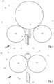
- FIGs. 1-4 schematically show an exemplifying embodiment of the invention in a winder 20 of a two-drum type slitter-winder.
- a fiber web W is guided for example from an unwinder to a slitter, in which the fiber web W is slitted in the longitudinal direction into narrower fiber webs for customer rolls 15.
- the fiber web W is after the slitter guided onto surface of first winding drum 10 and along the surface of the winding drum 10 through a winding nip N formed between the winding drum 10 and a customer roll 15 to be wound around the customer roll 15.
- the customer roll is created around a core or equivalent winding spool.
- the winder 20 also comprises a second winding drum 11 and during winding of the customer rolls 15 the customer rolls 15 are supported on both of the winding drums 10, 11.
- the second winding drum 11 may also be formed as a set of belt rolls depending on the type of two-drum winder in which an endless loop of belt/belts is arranged around two rolls.
- two adhesive application devices 31, 32 are arranged for applying adhesive.
- the adhesive application devices 31, 32 are arranged in cross-direction in respect of the longitudinal direction of the fiber web W movably on a support elements 33, 34.
- the adhesive application devices 31, 32 are thus movable along the support element 33, 34, correspondingly, which support elements 33, 34 extend in cross-direction in relation to the running direction of the fiber web W.
- the support elements 33, 34 are advantageously located such, that they extend a distance L over the corresponding edge of the fiber web W, which provides an acceleration/deceleration distance for the adhesive application device 31, 32 to be accelerated/decelerated to/from application speed before beginning of application of the adhesive substance / at end of application of the adhesive substance.
- the application position of the adhesive application devices 31, 32 and the support elements 33, 34 is located at about 3 o'clock position in view of the circumference of the winding drum 10 and thus, at 90 degrees from the winding nip N.
- the application devices 31, 32 and the support elements 33, 34 are located below the customer roll 15.
- the adhesive application devices 31, 32 and the support elements 33, 34 can also be located such, that the adhesive is applied on the surface of the customer roll 15 from below, as indicated by the dashed line position in figure 1 .
- the distance between the adhesive application point P and the winding nip N is less than 1000 mm measured as the travel distance of the fiber web W between the adhesive application point P and the winding nip N.
- the applied adhesive substance on the surface of the fiber web W enters the winding nip N for attaching the tail of the fiber web W to the surface of the customer roll 15 while the adhesive substance is still functioning (i.e. not hardened).
- the distance depends on the diameter of the winding drum and is thus, less than 1 ⁇ 4 of length of the diameter of the winding drum 10.
- one or both of the winding drums 10; 11 can be arranged to be movable away from the other / each other such, that required space for the application device 31, 32 and the support elements 33, 34 is provided between the winding drums 10, 11.
- the home position of the adhesive application device 31, 33 and the support elements 33, 34 is advantageously below the adhesive application position such, that the adhesive application devices 31, 32 and the support elements 33, 34 are substantially in vertical direction movable between the application and the home position.
- the application devices 31, 32 when applying the adhesive substance the application devices 31, 32 have a cross-directional movement i.e. a transverse movement in width direction of the fiber web W along the support elements 33, 34 to provide adhesive strip A31, A32 ( figs. 5-6 ) onto the surface of the fiber web W from a beginning position shown in figure 3 to end position shown in figure 4 .
- the application devices 32, 32 After the adhesive has been applied the application devices 32, 32 have a return movement correspondingly along the support elements 33, 34 and return to the beginning position ( fig. 3 ).
- FIG 5 is schematically shown the transverse / cross-directional location of the support element 33 of the adhesive application device in respect of the fiber web W for narrow webs, 2 - 7 m.
- the support element 33 of the adhesive application device is located in the transverse / cross-direction in relation to the running direction S of the fiber web W.
- the support element 33 is inclined in respect of the running direction S of the fiber web W such that the adhesive stripe A31 applied will be substantially transverse / cross-directional in relation to the running direction S of the fiber web W.
- FIG 6 is schematically shown the transverse / cross-directional location of the support elements 33, 34 of the adhesive applying devices in respect of the fiber web W for wide webs, 7 - 12 m.
- the support elements 33, 34 of the adhesive applying devices are located in the transverse / cross-direction in relation to the running direction S of the fiber web W.
- the support elements 33, 34 are inclined in respect of the running direction S of the fiber web W such that the adhesive stripes A31, A32 applied will be substantially transverse / cross-directional in relation to the running direction S of the fiber web W.
- the support elements 33, 34 are located substantially one after the other in the transverse / cross-direction such that one adhesive application device 31; 32 on the support element 33; 34 is used for part of the width of the fiber web W and the other one of the adhesive application devices 31, 32 is used for rest of the width of the fiber web W. As shown in the figure the support elements 33, 34 are advantageously partially overlapping in the middle area.
- Fig. 7 schematically shows an example in a multistation type slitter-winder, in which one winding drum 10 is used.
- a fiber web W is guided for example from an unwinder 50 to a slitter 51,52, in which the fiber web W is slitted in the longitudinal direction into narrower fiber webs for customer rolls 15.
- guide roll or a spreading roll 53 the fiber web W is guided onto surface of the winding drum 10 and along the surface of the winding drum 10 through a winding nip N formed between the winding drum 10 and the customer roll 15 to be wound around the customer roll 15.
- the customer roll is created around a core or equivalent winding spool.
- the multistation winder 20 may also comprise two winding nips along the circumference of the winding drum 10, typically at about ten-eleven o'clock and one-two o'clock positions.
- the multistation winder may also comprise two winding drums, one for one set of customer rolls and the other one for another set of the customer rolls.
- two adhesive application devices 31, 32 are arranged for applying adhesive.
- one of the adhesive application device may apply adhesive on the fiber web guided to one customer roll and the other to the other customer roll.
- two sets of adhesive application devices can be provided, one in connection with one winding drum and the other one with the other winding drum.
- the adhesive application devices 31, 32 are arranged in cross-direction in respect of the longitudinal direction of the fiber web W movably on a support element 33, 34.
- the adhesive application devices 31, 32 are thus movable along the support element 33, 34, correspondingly, which support elements 33, 34 extend in cross-direction in relation to the running direction of the fiber web W.
- the application position of the adhesive application devices 31, 32 and the support elements 33, 34 is located at about 9 o'clock position in view of the circumference of the winding drum 10 and thus, at 90 degrees from the winding nip N.
- the distance between the adhesive application point P and the winding nip N is less than 1000 mm measured as the travel distance of the fiber web W between the adhesive application point P and the winding nip N.
- the distance depends on the diameter of the winding drum and is thus, less than 1 ⁇ 4 of length of the diameter of the winding drum 10.
- transverse movements of the adhesive applying devices 31, 32 are used for applying the adhesive onto the fiber web W.
- one of the adhesive applying devices 31, 32 on at least part of the width of the fiber web W advantageously about half of the width of the fiber web W is provided with adhesive for attaching the tail of the fiber web W onto the wound customer roll 15 and during the movement of the other of the adhesive applying devices 31, 32 rest of the width of the fiber web W, advantageously about second half of the width of the fiber web is provided with adhesive.
Landscapes
- Replacement Of Web Rolls (AREA)
- Application Of Or Painting With Fluid Materials (AREA)
Abstract
Description
- The invention relates generally to production of fiber webs and to producing customer rolls of fiber webs, especially in a slitter-winder. The invention relates to a method of applying adhesive in a slitter-winder according to the preamble of the independent method claim. The invention also relates to a slitter-winder comprising a system of applying adhesive according to the preamble of the independent slitter-winder claim.
- It is known that fiber webs, e.g. paper and board webs, are manufactured in machines which together constitute a fiber web production line, which can be hundreds of meters long. As known from the prior art in fiber web production lines typically comprise an assembly formed by a number of apparatuses arranged consecutively in a process line. A typical production line for fiber web comprises a forming section comprising a head box and a wire section, a press section and a drying section and a reel-up. The production line can further comprise other sections and devices for treatment and/or finishing the fiber web, for example a sizer, a coating device, a calender. The production and treatment line also typically comprises at least one slitter-winder for forming customer rolls as well as a roll packaging apparatus. In present days running speeds of fiber web production lines, especially for certain fiber web grades for example for fluting and liner web grades, are so high that two slitter-winders are needed for slitting and winding the fiber web produced in the fiber web production lines.
- In fiber web production lines, the manufacture of the fiber web takes place as a continuous process. A fiber web completing in the fiber web production line is reeled by a reel-up around a reeling shaft i.e. a reel spool into a parent roll the diameter of which can be more than 5 meters and the weight more than 160 tons. The purpose of reeling is to modify the fiber web manufactured as planar and continuous to a more easily processable form. On the reel-up located in the main fiber web production line, the continuous process of the fiber web machine breaks for the first time and shifts into periodic operation. Reel-ups are thus used in fiber web production for reeling the fiber web coming from the fiber web production line into a parent roll, but reel-ups are also used to reel fiber web coming from a coating machine, a calender or a corresponding finishing device.
- The fiber web wound in the reel-up onto the parent roll is full-width so it must be slit in longitudinal direction into partial fiber webs with suitable width and the partial fiber webs are wound to partial fiber web rolls (customer rolls) with suitable length of fiber web or of suitable diameter for the customers. The slitting and winding take place as known from prior art in an appropriate separate machine i.e. in a slitter-winder. Slitter-winders employ winding devices of different types, for example multistation winders and two-drum winders. On slitter-winders of the multistation winder type, the fiber web is guided from the unwinding via guide rolls to the slitting section where the fiber web is slit into partial webs which are further guided either from above or from below to the winding roll/rolls of the winding stations to be wound up onto cores into customer rolls. Adjacent partial webs are wound up on different sides of the winding roll / on different winding rolls. Multistation winders have one to three winding rolls and in them each partial web is wound to a partial web roll in its own winding station. During winding a winding nip is formed between the winding roll and the partial web rolls to be wound. In the two-drum winders the partial webs are wound around winding cores supported by two winding drums to partial web rolls via a nip between the winding drums and the partial fiber web rolls being formed. In the two-drum winders also a belt arrangement i.e. a so-called set of belt rolls with belt loop or belt loops located around two guide rolls can be used as the winding drum. During winding a winding nip is formed between the winding drums and the partial web rolls to be wounds. As known in the prior art, also winding with a shaft without cores or together with cores can be employed in the winding of a fiber web into customer rolls on a slitter-winder.
- As known from the prior art, in the slitter-winder the parent roll is unwound in an unwinding section in at least one unwinder, the full-width fiber web is slit on the slitting section into several narrower partial fiber webs, which are wound up on a winding section around winding cores or around winding shafts or around winding cores located on the shafts, such as spools, into customer rolls. In the slitter-winder when the customer rolls reach desired length and diameter, the partial webs are cut in cross-direction. Tails of the partial webs are attached to the surface of customer rolls by applying adhesive to the surface of the fiber web, which adhesive then attaches the tails to the surface of the customer rolls. When the customer rolls are completed, the slitter-winder is stopped and the rolls i.e. the so-called set is removed from the machine after which the process is continued with the winding of a next set. These stages are repeated periodically until paper runs out of the parent roll in the unwinder, whereby a parent roll change is performed and the operation starts again as the unwinding of a next parent roll.
- In
WO publication 2008/148937 is described an apparatus for applying adhesive onto a moving web, containing an application head provided in connection with a support structure extending in the transverse direction across the fiber web, the support structure comprising a guide extending across the fiber web into which the application head has been disposed movably, and the application head has been arranged to form onto the surface of the fiber web an adhesive stripe essentially in the transverse direction in relation to the fiber web running direction while the fiber web is moving and the adhesive is brought to the surface of the fiber web during the decelerating movement of the fiber web. This prior art apparatus comprises means for changing the movement direction of the application head during the application of adhesive and/or that the application apparatus includes means for changing the movement speed of the application head during the application of adhesive. - In
WO publication 2011/076997 is disclosed an apparatus in a slitter-winder which comprises an applicator head which is arranged to apply the adhesive onto the fiber web surface and support member by means of which the apparatus can be mounted into the slitter-winder and by means of which the apparatus can be arranged to be movably substantially in cross-direction with respect to the slitter-winder. - In
EP patent publication 2666739B1 is disclosed a method of applying adhesive in a slitter-winder of a fiber web machine, which slitter-winder comprises an unwinder for unwinding a parent roll, slitting section for slitting a fiber web unwound from the parent roll into partial webs and winder with winding stations on at least one winding roll for winding the partial webs partial web rolls, in which method an adhesive application device is adapted to apply adhesive on ends of partial webs for attaching the ends of the partial webs onto the partial web rolls, in which method the device is moved in cross-direction of the main running direction of the partial webs over the width of the partial webs on a support element, in which method at least two transverse movements of at least one adhesive application device are used for applying the adhesive onto the partial webs and during the first movement of the adhesive application device at least a part set of the partial webs are provided with adhesive for attaching the tail of the partial web onto the wound partial web roll and during the second movement of the adhesive application device at least a part set of the partial webs not provided with adhesive during the first movement are provided with adhesive. - The above type of systems with transverse type of movement of the adhesive application device have in most cases proven to be well functioning but in order to create onto the fiber web surface a substantially in cross-direction extending an adhesive strip, running speed of the slitter-winder must be decreased and the adhesive application performed in crawling speed and thus, capacity of the slitter-winder decreases. Even though, this is question of some seconds, only, when targeting to performing customer roll production after a fiber web production line by utilizing only one slitter-winder, all savings in capacity are significant.
- In the systems according to prior art the adhesive application device has been located before the fiber web has been brought to contact with the first winding drum in the two-drum slitter-winders or with the winding drum (both in the following denoted by term "winding drum"). Typically, the adhesive application device has been located near or at a guiding or spreading roll preceding the first winding drum of the winding section of the slitter-winder. During the recent times adhesive substances have improved and fast-hardening adhesive substances have become increasingly popular due to their good adhesion properties. In the systems according to prior art such improved and fast-hardening substances have not been applicable due to long time it takes from adhesive application to the nip between the customer roll and the winding drum, in which the adhesive substance is pressed between the incoming fiber web and the almost finished customer roll to attach the tail of the fiber web to the surface of the customer roll. Thus, there exist a significant need to shorten the time between from adhesive application to the nip between the customer roll and the winding drum.
- An object of the invention is to create a method of applying adhesive in a slitter-winder, especially suitable for two-drum type of winders, in which the disadvantages of prior art are eliminated or at least minimized.
- A further object of the present invention is to create a slitter-winder, in particular a two-drum type slitter-winder, comprising a system of applying adhesive, in which the disadvantages of prior art are eliminated or at least minimized.
- To achieve the above-mentioned objects and those which come out later, the method according to the invention is mainly characterized by what is presented in the characterizing part of claim 1 The slitter-winder according to the invention, in turn, is mainly characterized by what is presented in the characterizing part of the independent slitter-winder claim. Advantageous features and embodiments of the invention are defined in dependent claims.
- It should be noted that in this description and the claims by transverse movement of an adhesive application device and by movement of an adhesive application device in cross-direction is meant a movement of the adhesive application device in direction that is transverse / cross-directional in relation to the running direction of the fiber web but if the fiber web is running during the movement of the adhesive application device the movement direction will be inclined in respect of the running direction of the fiber web such that at least last applied adhesive stripe will be substantially transverse / cross-directional in relation to the main running direction of the fiber web. Inclination is defined based on relation of running speed of the fiber web and application speed of the application device. Adhesive application can also be conducted such that the adhesive stripe/-s is/are inclined but then also cutting of the fiber web end would be conducted respectively inclined to avoid too long loose fiber web end on the customer roll.
- It should also be noted that in this description and the claims by adhesive is meant glue or other in fluid form applicable adhesive properties having substance i.e. adhesive that is applied by a nozzle or corresponding means such, that an adhesive stripe is provided on a surface of a moving fiber web.
- Further it should be noted that in this description and the claims by term "winding drum" is meant winding drums of a two-drum type slitter-winder and winding rolls of a multistation type slitter-winder contrary to the common use of these terms in the art for clarity reasons.
- According to the invention in the method of applying adhesive in a slitter-winder, which slitter-winder comprises a winder with at least one winding drum for winding a fiber web into a customer roll by a winding nip formed between the winding drum and the customer roll, at least one adhesive application device is adapted to apply adhesive on end of the fiber web, while the fiber web is moving, for attaching the end of the fiber web onto the customer roll, in which method the adhesive application device is moved in cross-direction of the running direction of the fiber web over at least partial width of the fiber web webs on a support element, wherein in the method the adhesive is applied on the fiber web at most 1000 mm before the adhesive on the fiber web reaches the winding nip.
- According to an advantageous feature of the invention in the method the adhesive is applied on the fiber web at an adhesive application point, the adhesive application point is located at a position, wherein the fiber web is running on the surface of the winding drum and angular distance between the winding nip and the adhesive application point on the winding drum is about 90 degrees.
- According to an advantageous feature of the invention in the method the adhesive is applied by two adhesive application devices, each located movably on the corresponding support elements such that one adhesive application device is used for applying adhesive over partial width of the fiber web, advantageously from one edge to about middle area of the fiber web, and the other adhesive application device is used for applying the adhesive over the rest of the width of the fiber web from the about middle area to the other edge.
- According to an advantageous feature of the invention in the middle area the adhesive application on the fiber web is overlapping.
- According to an advantageous feature of the invention in the method the adhesive is applied by two adhesive application devices, each located movably on a same support element such that one adhesive application device is used for applying adhesive over partial width of the fiber web, advantageously from one edge to about middle area of the fiber web, and the other adhesive application device is used for applying the adhesive over the rest of the width of the fiber web from the about middle area to the other edge.
- According to an advantageous feature of the invention the adhesive application device and the corresponding support element is moved from a home position, in which the adhesive application device and the corresponding support element is positioned while no adhesive is applied, in substantially vertical movement to an application position, in the application position adhesive is applied and after application of the adhesive the adhesive application device and the corresponding support element is returned to the home position by a substantially vertical movement.
- According to the invention the method is used in a two-drum winder, in a two-drum winder at least one of the winding drums is moved to provide space for the adhesive application device and the support element in between the winding drums for application of the adhesive on to the on the surface of the first winding drum moving fiber web.
- According to an advantageous feature of the invention in a two-drum winder the adhesive application device and the support element are positioned at a three o'clock position of the first winding drum.
- According to an advantageous feature of the invention in the method when the slitter-winder is decelerated for a set change the application device and the support element are moved to the adhesive application position, that the adhesive substance is applied during transversal movement of the application device from a beginning position of the adhesive application to an end position of the adhesive application on the corresponding support element.
- According to an advantageous feature of the invention in a home position the application device is located in mid area of the corresponding support element and in the application position moved to a beginning position and after the application of the adhesive substance the application device is moved to the home position.
- According to the invention the slitter-winder comprises a system of applying adhesive, in which slitter-winder the winder comprises at least one winding drum and which system of applying adhesive comprises at least one adhesive application device and at least one support element, on which support element the adhesive application device is movably arranged, wherein the adhesive application device and the support element are located in the adhesive application position next to the winding drum at a three o'clock or a nine o'clock position.
- According to an advantageous feature of the invention the adhesive application device and the support element are arranged substantially vertically movable between the adhesive application position and a home position, in which home position the adhesive application device and the support element are located, while no adhesive is applied.
- According to the invention the winder is a two-drum winder comprising two winding drums and the adhesive application device and the support element are located between the winding drums in the adhesive application position.
- According to the invention at least one of the winding drums is arranged movable such, that the space between the winding drums is adjustable.
- According to an advantageous feature of the invention in the winder a customer roll of fiber web is configured to be wound and the adhesive application device and the support element are located below the customer roll.
- According to an advantageous aspect of the invention the adhesive is applied onto the moving fiber web close to the winding nip, the distance the fiber web travels after applying the adhesive before entering the winding nip is less than 1000 mm.
- According to an advantageous aspect of the invention in a two-drum winder at least one of the winding drums is arranged movable to provide space for the adhesive application device in between the winding drums for application of the adhesive on to the on the surface of the first winding drum moving fiber web.
- According to an advantageous aspect of the invention in a two-drum winder the adhesive application device/-s are positioned at a three (3) o'clock position of the first winding drum to minimize the space requirement of the adhesive application device, as at this position the fiber web running direction is substantially vertical and thus only cross-directional inclination in respect of the running direction of the fiber web is needed for the support element/-s, on which the adhesive application device/-s are arranged movable in transversal movement.
- According to an advantageous aspect of the invention in a two-drum winder the adhesive application device/-s are located directly under the customer roll and the adhesive is applied onto the surface of the customer roll from below. This alternative is suitable in two-drum winders having well space in machine direction between the winding drums as this requires that the support elements inclination is provided in machine direction. Alternatively, cutting of the fiber web end should be conducted inclined.
- According to an advantageous aspect of the invention in a multistation winder the adhesive application device/-s are positioned at a nine (9) o'clock position of the first winding drum to minimize the space requirement of the adhesive application device, as at this position the fiber web running direction is substantially vertical and thus only cross-directional inclination in respect of the running direction of the fiber web is needed for the support element/-s, on which the adhesive application device/-s are arranged movable in transversal movement.
- According to an advantageous aspect of the invention in the method, when the slitter-winder is decelerated for the set change, the adhesive application device-Is and the support element/-s are lifted from a home position, which is advantageously underneath the level of the winding drum/-s and in which the adhesive application device/-s is/are advantageously in a home position in mid area of the support element/-s, to the adhesive application position in vertical direction. Advantageously, during the lifting stage the adhesive application device/-s are still in home position on the support element/-s. When the application device/-s and the support element/-s is/are in beginning position of the adhesive application in vertical direction, the adhesive application device/- s are moved to beginning position of the adhesive application on the support element/-s. The adhesive substance is applied during the movement of the application device/-s from the beginning position of the adhesive application to the end position of the adhesive application on the corresponding support element-/s. After application of the adhesive the application device/-s are returned to the home position on the mid area of the support element/-s and then the application device-Is and the support element/-s are lowered to the home position.
- Advantageously, for the application device/-s, the support element/-s are located such, that an accelerating/decelerating distance is provided for the adhesive application device/-s at the edges of the fiber web such, that the adhesive application device is in application speed at the beginning and end positions of the adhesive application.
- In the method according to an advantageous aspect of the invention the adhesive application device and the corresponding support element is moved from the home position, in which the adhesive application device and the corresponding support element is positioned while no adhesive is applied, in substantially vertical direction to the application position and adhesive is applied in the application position and the adhesive application device and s the support element is returned to the home position after application of the adhesive.
- According to another aspect of the method according to the invention adhesive can also be applied during the return movement of the adhesive applying device.
- In the method according to the invention advantageously an adhesive application device is used which has one adhesive nozzle but also a device with two adhesive nozzles that are attached to the adhesive application device, which is movable along the support element that extends the width of the partial webs in cross-direction in relation to the running direction of the fiber web, can be used.
- According to an advantageous aspect of the invention, especially in connection with wide webs to be slitted into partial webs, two adhesive application devices are used for applying the adhesive. The devices are located substantially one after the other in the transverse / cross-direction such that one device is used for applying adhesive to partial width of the fiber web, advantageously from one edge to about middle area of the fiber web and the other is used for applying the adhesive to the rest of the width of the fiber web from the about middle area to the other edge. The movements in the middle area are advantageously partially overlapping in the middle area. The construction in case of two adhesive application devices is advantageously provided such, that the two adhesive application do not collide, which provides advantages in maintenance and in cases malfunctioning occurs.
- According to one aspect of the invention also a device may also comprise two separate adhesive applying devices that are apart in the running direction of the fiber web.
- By the invention and its advantageous features several advantages are achieved: The adhesive application position being close to the winding nip than in prior art arrangements provides, that time is saved in the set change as the time for decelerating and crawling speed needed for the application of the adhesive properly, is remarkable shorter. Thus, a significant step for making it possible to use only one slitter-winder to take care of the customer rolls production after the fiber web production line is provided. Additionally, the invention provides for possibility of using improved and fast-hardening adhesive substances.
- Aspects of the invention, however, together with additional objects and advantages thereof, will be best understood from the following description of some example embodiments when read in connection with the accompanying drawings and in the following the invention is described in more detail referring to the accompanying drawing, in which
- In
figure 1 is schematically shown an advantageous example of the invention as an end view and the adhesive application device in application position. - In
figure 2 is schematically shown the advantageous example of thefigure 1 as an end view and the adhesive application device in home position. - In
figure 3 is schematically shown the advantageous example of thefigures 1-2 as a side view and the adhesive application device in application position and at the beginning of the transversal application movement. - In
figure 4 is schematically shown the advantageous example of thefigures 1-3 as a side view and the adhesive application device in application position and at the end of the transversal application movement. - In
figure 5 is schematically shown an example for narrow webs. - In
figure 6 is schematically shown an example for wide webs. - In
figure 7 is schematically shown an advantageous example in a multistation type slitter-winder. - In the following description same reference signs designate for similar components unless otherwise mentioned and it should be understood that the examples are susceptible of modification in order to adapt to different usages and conditions within the frames of the invention. Repetition of some reference signs may have been omitted in the figures for clarity reasons. In some of the figures an arrow has been used to indicate rotation direction of the respective main element of the construction.
-
Figs. 1-4 schematically show an exemplifying embodiment of the invention in awinder 20 of a two-drum type slitter-winder. A fiber web W is guided for example from an unwinder to a slitter, in which the fiber web W is slitted in the longitudinal direction into narrower fiber webs for customer rolls 15. The fiber web W is after the slitter guided onto surface of first windingdrum 10 and along the surface of the windingdrum 10 through a winding nip N formed between the windingdrum 10 and acustomer roll 15 to be wound around thecustomer roll 15. The customer roll is created around a core or equivalent winding spool. Thewinder 20 also comprises a second windingdrum 11 and during winding of the customer rolls 15 the customer rolls 15 are supported on both of the windingdrums drum 11 may also be formed as a set of belt rolls depending on the type of two-drum winder in which an endless loop of belt/belts is arranged around two rolls. - In the example of
figures 1-4 twoadhesive application devices adhesive application devices support elements adhesive application devices support element elements support elements adhesive application device figure 1 the application position of theadhesive application devices support elements drum 10 and thus, at 90 degrees from the winding nip N. As shown in the figures theapplication devices support elements customer roll 15. Theadhesive application devices support elements customer roll 15 from below, as indicated by the dashed line position infigure 1 . Advantageously, the distance between the adhesive application point P and the winding nip N is less than 1000 mm measured as the travel distance of the fiber web W between the adhesive application point P and the winding nip N. This provides that the applied adhesive substance on the surface of the fiber web W enters the winding nip N for attaching the tail of the fiber web W to the surface of thecustomer roll 15 while the adhesive substance is still functioning (i.e. not hardened). When the adhesive substance is applied on the surface of the fiber web W at the windingdrum 10, the distance depends on the diameter of the winding drum and is thus, less than ¼ of length of the diameter of the windingdrum 10. In cases the space between the two windingdrums drums 10; 11 can be arranged to be movable away from the other / each other such, that required space for theapplication device support elements drums figure 2 the home position of theadhesive application device support elements adhesive application devices support elements figures 3-4 when applying the adhesive substance theapplication devices support elements figs. 5-6 ) onto the surface of the fiber web W from a beginning position shown infigure 3 to end position shown infigure 4 . After the adhesive has been applied theapplication devices support elements fig. 3 ). - In
figure 5 is schematically shown the transverse / cross-directional location of thesupport element 33 of the adhesive application device in respect of the fiber web W for narrow webs, 2 - 7 m. Thesupport element 33 of the adhesive application device is located in the transverse / cross-direction in relation to the running direction S of the fiber web W. As the fiber web W is running during for the movement of the adhesive application device thesupport element 33 is inclined in respect of the running direction S of the fiber web W such that the adhesive stripe A31 applied will be substantially transverse / cross-directional in relation to the running direction S of the fiber web W. - In
figure 6 is schematically shown the transverse / cross-directional location of thesupport elements support elements support elements support elements adhesive application device 31; 32 on thesupport element 33; 34 is used for part of the width of the fiber web W and the other one of theadhesive application devices support elements -
Fig. 7 schematically shows an example in a multistation type slitter-winder, in which one windingdrum 10 is used. A fiber web W is guided for example from anunwinder 50 to aslitter roll 53 the fiber web W is guided onto surface of the windingdrum 10 and along the surface of the windingdrum 10 through a winding nip N formed between the windingdrum 10 and thecustomer roll 15 to be wound around thecustomer roll 15. The customer roll is created around a core or equivalent winding spool. Themultistation winder 20 may also comprise two winding nips along the circumference of the windingdrum 10, typically at about ten-eleven o'clock and one-two o'clock positions. The multistation winder may also comprise two winding drums, one for one set of customer rolls and the other one for another set of the customer rolls. In the example offigure 7 twoadhesive application devices adhesive application devices support element adhesive application devices support element elements adhesive application devices support elements drum 10 and thus, at 90 degrees from the winding nip N. Advantageously, the distance between the adhesive application point P and the winding nip N is less than 1000 mm measured as the travel distance of the fiber web W between the adhesive application point P and the winding nip N. Naturally, the distance depends on the diameter of the winding drum and is thus, less than ¼ of length of the diameter of the windingdrum 10. This provides that the applied adhesive substance on the surface of the fiber web W enters the winding nip N for attaching the tail of the fiber web W to the surface of thecustomer roll 15 while the adhesive substance is still functioning (i.e. not hardened). The home position of theadhesive application device support elements adhesive application devices - In the method transverse movements of the adhesive applying
devices devices wound customer roll 15 and during the movement of the other of the adhesive applyingdevices - In the description in the foregoing, although some functions have been described with reference to certain features, those functions may be performable by other features whether described or not. Although features have been described with reference to certain embodiments or examples, those features may also be present in other embodiments or examples whether described or not. Above the invention has been described by referring to some advantageous examples only to which the invention is not to be narrowly limited. Many modifications and alterations are possible within the invention as defined in the following claims.
-
- 10 winding drum
- 11 winding drum
- 15 customer roll
- 20 winder
- 31 application device
- 32 application device
- 33 support element
- 34 support element
- A31 adhesive substance
- A32 adhesive substance
- L distance
- N winding nip
- P adhesive application point
- S running direction of the fiber web
- W fiber web
- 50 unwinder
- 51, 52 slitter
- 53 spreading roll
Claims (12)
- Method of applying adhesive in a slitter-winder, which slitter-winder comprises a winder (20) with at least one winding drum (10) for winding a fiber web (W) into a customer roll (15) by a winding nip (N) formed between the winding drum (10) and the customer roll (15), in which method at least one adhesive application device (31, 32) is adapted to apply adhesive on end of the fiber web (W), while the fiber web (W) is moving, for attaching the end of the fiber web (W) onto the customer roll (15), in which method the adhesive application device (31; 32) is moved in cross-direction of the running direction of the fiber web (W) over at least partial width of the fiber web / webs on a support element (33; 34), characterized in, that in the method the adhesive is applied on the fiber web (W) at most 1000 mm before the adhesive on the fiber web (W) reaches the winding nip (N), that the method is used in a two-drum winder (20), that in the two-drum winder at least one of the winding drums (10, 11) is moved to provide space for the adhesive application device (31, 32) and the support element (33, 34) in between the winding drums (10, 11) for application of the adhesive on to the on the surface of the first winding drum (10) moving fiber web (W).
- Method according to claim 1, characterized in, that in the method the adhesive is applied on the fiber web (W) at an adhesive application point (P), that the adhesive application point (P) is located at a position, wherein the fiber web (W) is running on the surface of the winding drum (10) and that angular distance between the winding nip (N) and the adhesive application point (P) on the winding drum (10) is about 90 degrees.
- Method according to claim 1 or 2, characterized in, that in the method the adhesive is applied by two adhesive application devices (31, 32), each located movably on the corresponding support elements (33, 34) such that one adhesive application device (31) is used for applying adhesive over partial width of the fiber web (W), advantageously from one edge to about middle area of the fiber web (W), and the other adhesive application device (32) is used for applying the adhesive over the rest of the width of the fiber web (W) from the about middle area to the other edge.
- Method according to claim 3, characterized in, that in the middle area the adhesive application on the fiber web (W) is overlapping.
- Method according to any of claims 1-4, characterized in, that in the method the adhesive is applied by two adhesive application devices (31, 32), each located movably on a same support element (33; 34) such that one adhesive application device (31) is used for applying adhesive over partial width of the fiber web (W), advantageously from one edge to about middle area of the fiber web (W), and the other adhesive application device (32) is used for applying the adhesive over the rest of the width of the fiber web (W) from the about middle area to the other edge.
- Method according to any of claims 1-5, characterized in, that the adhesive application device (31, 32) and the corresponding support element (33, 34) is moved from a home position, in which the adhesive application device (31, 32) and the corresponding support element (33, 34) is positioned while no adhesive is applied, in substantially vertical movement to an application position, that in the application position adhesive is applied and that after application of the adhesive the adhesive application device (31, 32) and the corresponding support element (33, 34) is returned to the home position by a substantially vertical movement.
- Method according to any of claims 1-6, characterized in, that in the two-drum winder the adhesive application device (31, 32) and the support element (33, 34) are positioned at a three (3) o'clock position of the first winding drum (11).
- Method according to any of claims 1-7, characterized in, that in the method when the slitter-winder is decelerated for a set change the application device (31, 32) and the support element (33, 34) are moved to the adhesive application position, that the adhesive substance is applied during transversal movement of the application device (31, 32) from a beginning position of the adhesive application to an end position of the adhesive application on the corresponding support element (33, 34).
- Method according to any of claims 1-8, characterized in, that in a home position the application device (31, 32) is located in mid area of the corresponding support element (33, 34) and in the application position moved to a beginning position and after the application of the adhesive substance the application device is moved to the home position.
- Slitter-winder comprising a system of applying adhesive, in which slitter-winder the winder (20) comprises at least one winding drum (10) and which system of applying adhesive comprises at least one adhesive application device (31, 32) and at least one support element (33, 34), on which support element (33, 34) the adhesive application device (31, 32) is movably arranged, characterized in, that the winder (20) is a two-drum winder comprising two winding drums (10, 11) and that the adhesive application device (31, 32) and the support element (33, 34) are located between the winding drums (10, 11) in the adhesive application position, that at least one of the winding drums (10, 11) is arranged movable such, that the space between the winding drums (10, 11) is adjustable, that the adhesive application device (31, 32) and the support element (33, 34) are located in the adhesive application position next to the winding drum (10) at a three o'clock or a nine o'clock position.
- Slitter-winder according to claim 10, characterized in, that the adhesive application device (31, 32) and the support element (33, 34) are arranged substantially vertically movable between the adhesive application position and a home position, in which home position the adhesive application device (31, 32) and the support element (33, 34) are located, while no adhesive is applied.
- Slitter-winder according to claim 10 or 11, characterized in, that in the winder a customer roll (15) of fiber web (W) is configured to be wound and that the adhesive application device (31, 32) and the support element (33, 34) are located below the customer roll.
Applications Claiming Priority (1)
| Application Number | Priority Date | Filing Date | Title |
|---|---|---|---|
| FI20235553A FI131307B1 (en) | 2023-05-16 | 2023-05-16 | Method of applying adhesive in a slitter-winder and a slitter-winder comprising a system of applying adhesive |
Publications (2)
| Publication Number | Publication Date |
|---|---|
| EP4477590A1 true EP4477590A1 (en) | 2024-12-18 |
| EP4477590B1 EP4477590B1 (en) | 2025-07-09 |
Family
ID=90730327
Family Applications (1)
| Application Number | Title | Priority Date | Filing Date |
|---|---|---|---|
| EP24169907.3A Active EP4477590B1 (en) | 2023-05-16 | 2024-04-12 | Method of applying adhesive in a slitter-winder and a slitter-winder comprising a system of applying adhesive |
Country Status (3)
| Country | Link |
|---|---|
| EP (1) | EP4477590B1 (en) |
| CN (1) | CN118992647A (en) |
| FI (1) | FI131307B1 (en) |
Citations (6)
| Publication number | Priority date | Publication date | Assignee | Title |
|---|---|---|---|---|
| US4572451A (en) * | 1982-12-27 | 1986-02-25 | Ishikawajima-Harima Jukogyo Kabushiki Kaisha | Method and device for winding paper |
| US4711405A (en) * | 1984-11-27 | 1987-12-08 | Oy Wartsila Ab | Method and apparatus for fixing an end of a web on a core tube in a web reeling machine |
| GB2249542A (en) * | 1990-11-06 | 1992-05-13 | Stahlkontor Maschinenbau | Winding webs continuously |
| WO2008148937A1 (en) | 2007-06-05 | 2008-12-11 | Metso Paper, Inc. | Method of using a slitter winder and apparatus for applying adhesive |
| WO2011076997A1 (en) | 2009-12-22 | 2011-06-30 | Metso Paper, Inc. | Winding section in a slitter winder for a fibrous web and apparatus for bringing a fastening means onto the surface of a partial web |
| EP2666739B1 (en) | 2012-05-23 | 2015-04-29 | Valmet Technologies, Inc. | Method of applying adhesive in a slitter-winder of fiber web machine |
Family Cites Families (2)
| Publication number | Priority date | Publication date | Assignee | Title |
|---|---|---|---|---|
| DE102019101725A1 (en) * | 2019-01-24 | 2020-07-30 | Voith Patent Gmbh | Web overpass when winding |
| DE102019110233A1 (en) * | 2019-04-18 | 2020-10-22 | Voith Patent Gmbh | Winding process |
-
2023
- 2023-05-16 FI FI20235553A patent/FI131307B1/en active
-
2024
- 2024-04-12 EP EP24169907.3A patent/EP4477590B1/en active Active
- 2024-05-15 CN CN202410603970.4A patent/CN118992647A/en active Pending
Patent Citations (6)
| Publication number | Priority date | Publication date | Assignee | Title |
|---|---|---|---|---|
| US4572451A (en) * | 1982-12-27 | 1986-02-25 | Ishikawajima-Harima Jukogyo Kabushiki Kaisha | Method and device for winding paper |
| US4711405A (en) * | 1984-11-27 | 1987-12-08 | Oy Wartsila Ab | Method and apparatus for fixing an end of a web on a core tube in a web reeling machine |
| GB2249542A (en) * | 1990-11-06 | 1992-05-13 | Stahlkontor Maschinenbau | Winding webs continuously |
| WO2008148937A1 (en) | 2007-06-05 | 2008-12-11 | Metso Paper, Inc. | Method of using a slitter winder and apparatus for applying adhesive |
| WO2011076997A1 (en) | 2009-12-22 | 2011-06-30 | Metso Paper, Inc. | Winding section in a slitter winder for a fibrous web and apparatus for bringing a fastening means onto the surface of a partial web |
| EP2666739B1 (en) | 2012-05-23 | 2015-04-29 | Valmet Technologies, Inc. | Method of applying adhesive in a slitter-winder of fiber web machine |
Also Published As
| Publication number | Publication date |
|---|---|
| CN118992647A (en) | 2024-11-22 |
| FI20235553A1 (en) | 2024-11-17 |
| FI131307B1 (en) | 2025-02-04 |
| EP4477590B1 (en) | 2025-07-09 |
Similar Documents
| Publication | Publication Date | Title |
|---|---|---|
| JPH09124198A (en) | Method and device for taking up of paper web or paperboard web | |
| US9260266B2 (en) | Method for separating partial webs in a slitter winder | |
| EP4105155B1 (en) | A method and a device for joining ends of fiber webs in a parent roll change of an unwinder | |
| EP2666739B1 (en) | Method of applying adhesive in a slitter-winder of fiber web machine | |
| EP2653422A1 (en) | Method and device for winding of fiber webs, especially of partial paper and board webs | |
| EP4477590B1 (en) | Method of applying adhesive in a slitter-winder and a slitter-winder comprising a system of applying adhesive | |
| EP2516302B1 (en) | Winding section in a slitter winder for a fibrous web and apparatus for bringing a fastening means onto the surface of a partial web | |
| US8807066B2 (en) | Device for applying adhesive in a slitter-winder of fiber web machine | |
| FI130645B1 (en) | Slitter-winder and a method for slitting and winding a fiber web | |
| EP1152969B1 (en) | Method and apparatus for winding a paper web | |
| EP2543616B1 (en) | Arrangement in a slitter-winder for a fiber web machine | |
| EP4477591B1 (en) | Unwinding section and a method of joining ends of fiber webs in an unwinding section | |
| EP2540649B1 (en) | Method and arrangement in connection with an unwinder | |
| FI132015B1 (en) | Friction measuring system and a friction measuring method for measurement of friction of a fiber web in connection with an unwinder of a slitter-winder | |
| EP4230793B1 (en) | Method and system of producing of fiber webs | |
| EP2664567B1 (en) | Method for web threading in a slitter-winder and a slitter-winder | |
| US6964393B1 (en) | Method in sequential winding stations and production line comprising sequential winding stations | |
| FI20215702A1 (en) | A joint and a device for joining fiber web ends | |
| CN113840790A (en) | Material web unwinding |
Legal Events
| Date | Code | Title | Description |
|---|---|---|---|
| PUAI | Public reference made under article 153(3) epc to a published international application that has entered the european phase |
Free format text: ORIGINAL CODE: 0009012 |
|
| STAA | Information on the status of an ep patent application or granted ep patent |
Free format text: STATUS: THE APPLICATION HAS BEEN PUBLISHED |
|
| AK | Designated contracting states |
Kind code of ref document: A1 Designated state(s): AL AT BE BG CH CY CZ DE DK EE ES FI FR GB GR HR HU IE IS IT LI LT LU LV MC ME MK MT NL NO PL PT RO RS SE SI SK SM TR |
|
| STAA | Information on the status of an ep patent application or granted ep patent |
Free format text: STATUS: REQUEST FOR EXAMINATION WAS MADE |
|
| 17P | Request for examination filed |
Effective date: 20250108 |
|
| GRAP | Despatch of communication of intention to grant a patent |
Free format text: ORIGINAL CODE: EPIDOSNIGR1 |
|
| STAA | Information on the status of an ep patent application or granted ep patent |
Free format text: STATUS: GRANT OF PATENT IS INTENDED |
|
| GRAS | Grant fee paid |
Free format text: ORIGINAL CODE: EPIDOSNIGR3 |
|
| GRAA | (expected) grant |
Free format text: ORIGINAL CODE: 0009210 |
|
| STAA | Information on the status of an ep patent application or granted ep patent |
Free format text: STATUS: THE PATENT HAS BEEN GRANTED |
|
| INTG | Intention to grant announced |
Effective date: 20250520 |
|
| AK | Designated contracting states |
Kind code of ref document: B1 Designated state(s): AL AT BE BG CH CY CZ DE DK EE ES FI FR GB GR HR HU IE IS IT LI LT LU LV MC ME MK MT NL NO PL PT RO RS SE SI SK SM TR |
|
| REG | Reference to a national code |
Ref country code: GB Ref legal event code: FG4D |
|
| REG | Reference to a national code |
Ref country code: CH Ref legal event code: EP |
|
| REG | Reference to a national code |
Ref country code: IE Ref legal event code: FG4D |
|
| REG | Reference to a national code |
Ref country code: DE Ref legal event code: R096 Ref document number: 602024000286 Country of ref document: DE |
|
| REG | Reference to a national code |
Ref country code: NL Ref legal event code: MP Effective date: 20250709 |
|
| PG25 | Lapsed in a contracting state [announced via postgrant information from national office to epo] |
Ref country code: PT Free format text: LAPSE BECAUSE OF FAILURE TO SUBMIT A TRANSLATION OF THE DESCRIPTION OR TO PAY THE FEE WITHIN THE PRESCRIBED TIME-LIMIT Effective date: 20251110 |
|
| PG25 | Lapsed in a contracting state [announced via postgrant information from national office to epo] |
Ref country code: NL Free format text: LAPSE BECAUSE OF FAILURE TO SUBMIT A TRANSLATION OF THE DESCRIPTION OR TO PAY THE FEE WITHIN THE PRESCRIBED TIME-LIMIT Effective date: 20250709 |
|
| PG25 | Lapsed in a contracting state [announced via postgrant information from national office to epo] |
Ref country code: IS Free format text: LAPSE BECAUSE OF FAILURE TO SUBMIT A TRANSLATION OF THE DESCRIPTION OR TO PAY THE FEE WITHIN THE PRESCRIBED TIME-LIMIT Effective date: 20251109 |
|
| PG25 | Lapsed in a contracting state [announced via postgrant information from national office to epo] |
Ref country code: NO Free format text: LAPSE BECAUSE OF FAILURE TO SUBMIT A TRANSLATION OF THE DESCRIPTION OR TO PAY THE FEE WITHIN THE PRESCRIBED TIME-LIMIT Effective date: 20251009 |
|
| REG | Reference to a national code |
Ref country code: LT Ref legal event code: MG9D |
|
| PG25 | Lapsed in a contracting state [announced via postgrant information from national office to epo] |
Ref country code: FI Free format text: LAPSE BECAUSE OF FAILURE TO SUBMIT A TRANSLATION OF THE DESCRIPTION OR TO PAY THE FEE WITHIN THE PRESCRIBED TIME-LIMIT Effective date: 20250709 |
|
| PG25 | Lapsed in a contracting state [announced via postgrant information from national office to epo] |
Ref country code: HR Free format text: LAPSE BECAUSE OF FAILURE TO SUBMIT A TRANSLATION OF THE DESCRIPTION OR TO PAY THE FEE WITHIN THE PRESCRIBED TIME-LIMIT Effective date: 20250709 |
|
| PG25 | Lapsed in a contracting state [announced via postgrant information from national office to epo] |
Ref country code: GR Free format text: LAPSE BECAUSE OF FAILURE TO SUBMIT A TRANSLATION OF THE DESCRIPTION OR TO PAY THE FEE WITHIN THE PRESCRIBED TIME-LIMIT Effective date: 20251010 |
|
| PG25 | Lapsed in a contracting state [announced via postgrant information from national office to epo] |
Ref country code: SE Free format text: LAPSE BECAUSE OF FAILURE TO SUBMIT A TRANSLATION OF THE DESCRIPTION OR TO PAY THE FEE WITHIN THE PRESCRIBED TIME-LIMIT Effective date: 20250709 |
|
| PG25 | Lapsed in a contracting state [announced via postgrant information from national office to epo] |
Ref country code: LV Free format text: LAPSE BECAUSE OF FAILURE TO SUBMIT A TRANSLATION OF THE DESCRIPTION OR TO PAY THE FEE WITHIN THE PRESCRIBED TIME-LIMIT Effective date: 20250709 |
|
| PG25 | Lapsed in a contracting state [announced via postgrant information from national office to epo] |
Ref country code: PL Free format text: LAPSE BECAUSE OF FAILURE TO SUBMIT A TRANSLATION OF THE DESCRIPTION OR TO PAY THE FEE WITHIN THE PRESCRIBED TIME-LIMIT Effective date: 20250709 Ref country code: BG Free format text: LAPSE BECAUSE OF FAILURE TO SUBMIT A TRANSLATION OF THE DESCRIPTION OR TO PAY THE FEE WITHIN THE PRESCRIBED TIME-LIMIT Effective date: 20250709 |
|
| PG25 | Lapsed in a contracting state [announced via postgrant information from national office to epo] |
Ref country code: RS Free format text: LAPSE BECAUSE OF FAILURE TO SUBMIT A TRANSLATION OF THE DESCRIPTION OR TO PAY THE FEE WITHIN THE PRESCRIBED TIME-LIMIT Effective date: 20251009 |
|
| PG25 | Lapsed in a contracting state [announced via postgrant information from national office to epo] |
Ref country code: ES Free format text: LAPSE BECAUSE OF FAILURE TO SUBMIT A TRANSLATION OF THE DESCRIPTION OR TO PAY THE FEE WITHIN THE PRESCRIBED TIME-LIMIT Effective date: 20250709 |
|
| PG25 | Lapsed in a contracting state [announced via postgrant information from national office to epo] |
Ref country code: SM Free format text: LAPSE BECAUSE OF FAILURE TO SUBMIT A TRANSLATION OF THE DESCRIPTION OR TO PAY THE FEE WITHIN THE PRESCRIBED TIME-LIMIT Effective date: 20250709 |
|
| PG25 | Lapsed in a contracting state [announced via postgrant information from national office to epo] |
Ref country code: DK Free format text: LAPSE BECAUSE OF FAILURE TO SUBMIT A TRANSLATION OF THE DESCRIPTION OR TO PAY THE FEE WITHIN THE PRESCRIBED TIME-LIMIT Effective date: 20250709 |
|
| PG25 | Lapsed in a contracting state [announced via postgrant information from national office to epo] |
Ref country code: CZ Free format text: LAPSE BECAUSE OF FAILURE TO SUBMIT A TRANSLATION OF THE DESCRIPTION OR TO PAY THE FEE WITHIN THE PRESCRIBED TIME-LIMIT Effective date: 20250709 |
|
| PG25 | Lapsed in a contracting state [announced via postgrant information from national office to epo] |
Ref country code: EE Free format text: LAPSE BECAUSE OF FAILURE TO SUBMIT A TRANSLATION OF THE DESCRIPTION OR TO PAY THE FEE WITHIN THE PRESCRIBED TIME-LIMIT Effective date: 20250709 Ref country code: SK Free format text: LAPSE BECAUSE OF FAILURE TO SUBMIT A TRANSLATION OF THE DESCRIPTION OR TO PAY THE FEE WITHIN THE PRESCRIBED TIME-LIMIT Effective date: 20250709 |
|
| PLBE | No opposition filed within time limit |
Free format text: ORIGINAL CODE: 0009261 |
|
| STAA | Information on the status of an ep patent application or granted ep patent |
Free format text: STATUS: NO OPPOSITION FILED WITHIN TIME LIMIT |