EP4477529A1 - Barrier door for an aircraft - Google Patents
Barrier door for an aircraft Download PDFInfo
- Publication number
- EP4477529A1 EP4477529A1 EP24165860.8A EP24165860A EP4477529A1 EP 4477529 A1 EP4477529 A1 EP 4477529A1 EP 24165860 A EP24165860 A EP 24165860A EP 4477529 A1 EP4477529 A1 EP 4477529A1
- Authority
- EP
- European Patent Office
- Prior art keywords
- pin
- barrier door
- elongated member
- sleeve
- opening
- Prior art date
- Legal status (The legal status is an assumption and is not a legal conclusion. Google has not performed a legal analysis and makes no representation as to the accuracy of the status listed.)
- Granted
Links
Images






Classifications
-
- B—PERFORMING OPERATIONS; TRANSPORTING
- B64—AIRCRAFT; AVIATION; COSMONAUTICS
- B64C—AEROPLANES; HELICOPTERS
- B64C1/00—Fuselages; Constructional features common to fuselages, wings, stabilising surfaces or the like
- B64C1/14—Windows; Doors; Hatch covers or access panels; Surrounding frame structures; Canopies; Windscreens accessories therefor, e.g. pressure sensors, water deflectors, hinges, seals, handles, latches, windscreen wipers
- B64C1/1407—Doors; surrounding frames
- B64C1/1469—Doors between cockpit and cabin
-
- B—PERFORMING OPERATIONS; TRANSPORTING
- B64—AIRCRAFT; AVIATION; COSMONAUTICS
- B64D—EQUIPMENT FOR FITTING IN OR TO AIRCRAFT; FLIGHT SUITS; PARACHUTES; ARRANGEMENT OR MOUNTING OF POWER PLANTS OR PROPULSION TRANSMISSIONS IN AIRCRAFT
- B64D45/00—Aircraft indicators or protectors not otherwise provided for
- B64D45/0015—Devices specially adapted for the protection against criminal attack, e.g. anti-hijacking systems
- B64D45/0021—Devices specially adapted for the protection against criminal attack, e.g. anti-hijacking systems means for restricting access to flight deck
- B64D45/0028—Devices specially adapted for the protection against criminal attack, e.g. anti-hijacking systems means for restricting access to flight deck doors or door arrangements specially adapted to restrict unauthorized access
-
- E—FIXED CONSTRUCTIONS
- E05—LOCKS; KEYS; WINDOW OR DOOR FITTINGS; SAFES
- E05C—BOLTS OR FASTENING DEVICES FOR WINGS, SPECIALLY FOR DOORS OR WINDOWS
- E05C9/00—Arrangements of simultaneously actuated bolts or other securing devices at well-separated positions on the same wing
- E05C9/04—Arrangements of simultaneously actuated bolts or other securing devices at well-separated positions on the same wing with two sliding bars moved in opposite directions when fastening or unfastening
- E05C9/041—Arrangements of simultaneously actuated bolts or other securing devices at well-separated positions on the same wing with two sliding bars moved in opposite directions when fastening or unfastening with rack and pinion mechanism
Definitions
- the present disclosure relates generally to the field of barriers and, more specifically, to barrier doors configured to be used within an aircraft.
- Aircraft have a flight deck that includes flight instruments, instrument panels, and various controls that enable the flight personnel to operate the aircraft.
- the flight deck is positioned towards the front of the aircraft and is usually a separate compartment away from the cabin area where passengers sit during flight.
- a flight deck door further separates the flight deck from the cabin area.
- the flight deck door is closed and locked during flight. This allows the flight personnel to concentrate on operating the aircraft and prevents entry of unwanted persons onto the flight deck.
- the flight deck door may be opened during flight for various reasons. One occurrence is when the flight personnel use the lavatory which is located in the cabin area of the aircraft. Other occurrences are when food and/or drinks that are prepared in the galley of the cabin area are delivered to the flight personnel on the flight deck, and when flight personnel leave the flight deck during a break.
- Opening of the flight deck door could present an opportunity for an unwanted person to gain entry to the flight deck.
- the unwanted person could suddenly rush the front of the aircraft once the flight deck door is opened and force their way into the flight deck. It would be difficult for flight personnel working in the cabin area to react to this movement in a fast enough manner to close and lock the flight deck door.
- a device is needed that would inhibit a person in the cabin area from rushing towards the flight deck.
- the device would prevent the person from reaching the front of the aircraft or would slow their movement such that the flight deck door could be closed and locked prior to the person reaching the flight deck.
- the barrier door comprises a body comprising an upper side, a lower side, and lateral sides.
- a lock is connected to the body and comprises a cylinder with an elongated shape comprising an inner end and an outer end and an interior space that is hollow, a pin positioned within the interior space of the cylinder and movable between a disengaged position with a distal end retracted within the interior space and an engaged position with the distal end extending outward beyond the outer end of the cylinder, a biasing member that biases the pin towards the engaged position, and a release mechanism threaded to the inner end of the cylinder with the release mechanism rotatable relative to the cylinder to adjust a position of the cylinder and pin relative to the body.
- the outer end of the cylinder is aligned with the upper side of the body for the pin to extend outward beyond the body in the engaged position.
- a handle extends outward from the pin and an opening in the cylinder is in communication with the interior space with the opening comprising a first section and a second section and the handle is in the first section of the opening when the pin is in the disengaged position and in the second section of the opening when the pin is in the engaged position.
- the body comprises a first side and a second side and the handle extends outward beyond the first side of the body and is positioned away from the second side of the body.
- an opening is in the body and the release mechanism comprises a sleeve with the sleeve positioned in the opening and the sleeve is accessible from both the first side of the body and the second side of the body.
- the release mechanism comprises a sleeve that extends around the inner end of the cylinder with the sleeve comprising interior threads and the cylinder comprising exterior threads.
- a receptacle is configured to be mounted in proximity to the body with the receptacle comprising a biased plug sized to contact against the distal end of the pin when the pin is in the engaged position.
- the body comprises a plurality of vertical slats that are hingedly connected together with the barrier door movable between an open position with the vertical slats in a folded configuration and a closed position with the vertical slats in an unfolded configuration.
- the pin is fixedly positioned relative to the cylinder during rotation of the release mechanism.
- the barrier door comprises a body comprising an outer perimeter.
- a sleeve is connected to the body.
- a first elongated member is connected to and extends outward from the sleeve in a first direction.
- a second elongated member is connected to and extends outward from the sleeve in a second direction.
- a first pin is connected to the first elongated member and a second pin is connected to the second elongated member.
- the first pin and the second pin are movable between retracted positions that are inward within the outer perimeter of the body and extended positions that are outward beyond the outer perimeter of the body.
- the sleeve is rotatable relative to the first elongated member and the second elongated member to move both of the first pin and the second pin inward within the outer perimeter of the body in the extended positions.
- each of the first elongated member and the second elongated member are cylinders with a hollow interior space and the first pin is positioned within the first elongated member and the second pin is positioned within the second elongated member.
- the sleeve is positioned along a central section of the body and the first elongated member extends outward towards an upper side of the body with the first pin extending outward beyond the upper side of the body in the extended position.
- the second elongated member extends outward towards a lower side of the body with the second pin extending outward beyond the lower side of the body in the extended position.
- first pin is fixedly positioned relative to the first elongated member during rotation of the sleeve and the second pin is fixedly positioned relative to the second elongated member during rotation of the sleeve.
- the sleeve, the first elongated member, and the second elongated member are aligned together and extend along a lateral side of the body.
- the sleeve is connected with threads to each of the first elongated member and the second elongated member.
- each of the first pin and the second pin comprise a main body with a proximal end and a distal end and a handle that extends outward from the main body between the proximal end of the distal end with the handle extending outward from the respective first elongated member and the second elongated member in the retracted position.
- the method further comprises moving the first pin within a first cylinder and extending a distal end of the first pin outward beyond the upper side of the body and engaging the ceiling and moving the second pin within a second cylinder and extending a distal end of the second pin outward beyond the lower side of the body and engaging the floor.
- Figures 1 and 2 illustrate an aircraft 100 that includes a fuselage 101.
- a flight deck 110 is positioned at a front of the fuselage 101 and a cabin area 103 is positioned rearward.
- the cabin area 103 is equipped for accommodating passengers.
- the size of the flight deck 110 and the cabin area 103 can vary depending upon the aircraft 100.
- One or more exterior doors 104 provide for passengers and the flight personnel to enter and exit the fuselage 101.
- the flight deck 110 includes one or more seats 111 for the flight personnel including but not limited to the pilot, co-pilot, and other authorized persons.
- Various controls and instrument panels are located for use by the pilot and co-pilot to control the aircraft 100.
- the cabin area 103 is positioned along the fuselage 101 rearward of the flight deck 110.
- the cabin area 103 includes a passenger section 121 with seats 105 arranged in rows along one or more aisles 106.
- the seats 105 extend throughout the cabin area 103.
- a limited number of seats 105 are positioned in the cabin area 103.
- the cabin area 103 also includes a vestibule 120 positioned between the flight deck 110 and the passenger section 121.
- the vestibule 120 includes one or more monuments 112 that are mounted to the structural members of the aircraft 100 within the fuselage 101.
- the monuments 112 are functional units with examples including but not limited to galleys, lavatories, and stowage units.
- the monuments 112 are shaped and sized to extend from the floor 107 to the ceiling 108 of the cabin area 103.
- the monuments 112 extend between a wall 114 of the fuselage 101 to an aisle 106.
- Figure 2 includes the vestibule 120 including a pair of galley monuments 112a, 112b, a lavatory monument 112c, and a stowage monument 112d.
- a flight deck door 90 separates the flight deck 110 from the cabin area 103, and in some examples specifically separates the flight deck 110 from the vestibule 120.
- the flight deck door 90 prevents unintended persons from entering the flight deck 110 from the cabin area 103.
- the flight deck door 90 includes a lock 91 configured to secure the door 90 in the closed position.
- the lock 91 can include various configurations for unlocking, such as a magnetic card reader and input buttons.
- a viewing hole 92 provides for the flight personnel on the flight deck 110 to see into the cabin area 103 without opening the door 90.
- the door 90 is mounted in a frame 109 that mounts onto one or more of the monuments 112, floor 107, and ceiling 108.
- the cabin area 103 further includes an opening 113 in proximity to the flight deck 110.
- the opening 113 is formed between two monuments - galley monument 112b and lavatory monument 112c.
- Other examples include the opening 113 formed between monuments 112b and 112d, and the opening 113 formed between monuments 112a and 112c.
- Other examples include the opening 113 formed between various components, such as monuments 112, walls 114 of the fuselage 101, and seats 105.
- a barrier door 20 is positioned at the opening 113 and includes a front side 21 that faces towards the front of the aircraft 100 and an opposing rear side 22.
- the barrier door 20 is movable between an open position and a closed position (as illustrated in Figure 2 ).
- the barrier door 20 In the open position the barrier door 20 is retracted or otherwise configured to allow people to pass through the opening 113, such as for passengers to use the lavatory 112c or flight personnel to move between the flight deck 110 and passenger section 121.
- the barrier door 20 In the closed position, the barrier door 20 extends across and is locked within the opening 113.
- the barrier door 20 functions to delay or otherwise slow the movement of a person moving from the passenger section 121 towards the flight deck 110. This time provides for the flight deck door 90 to be closed and locked.
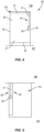
- Figure 4 schematically illustrates a barrier door 20 in a closed position.
- the barrier door 20 includes a body 30 sized to extend across the opening 113.
- a lock 40 that includes one or more elongated members 41 is secured to the body 30 and movable between engaged and disengaged positions. In the engaged position, the one or more elongated members 41 extend outward and engage with the structure of the aircraft 100 to maintain the barrier door 20 in the closed position.
- the structure of the aircraft 100 can include but is not limited to one or more of the floor 107, ceiling 108, monument 112, seat 105, frame 109, and outer wall 114.
- the lock 40 further includes a release mechanism 50 that provides for moving the one or more elongated members 41 to the disengaged position. In the disengaged position as illustrated in Figure 5 , the one or more elongated members 41 are retracted away from the structure of the aircraft 100 to allow for the barrier door 20 to move between the open and closed positions.
- the body 30 can include various shapes and sizes.
- the body 30 in the closed position is rectangular and includes an upper side 31, lower side 32, and lateral sides 33, 34 and is sized to extend across the opening 113.
- the body 30 is sized to completely fill the opening 113.
- the body 30 is smaller than the opening 113 with one or more gaps positioned between the body 30 and the edges of the opening 113.
- the barrier door 20 is positioned to allow persons to move through the opening 113.
- the body 30 can fold or otherwise retract to fill a limited portion of the opening 113 and allow for persons to pass.
- the body 30 is connected to the structure of the aircraft such as along one of the lateral sides and pivots on a hinge away from the opening 113.
- a mount 36 is configured to mount the body 30 in the opening 113.
- the mount 36 is positioned on the lateral side 33 and includes pins 37, 38 that extend outward beyond the upper and lower sides 31, 32 to engaged with the ceiling 108 and floor 107 respectively.
- the mount 36 provides for the body 30 to be pivotally mounted in the opening 113.
- the lock 40 secures the door 20 in the closed position.
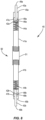
- the lock 40 is attached to the body 30 and can be positioned at various locations. In one example as illustrated in Figure 6 , the lock 40 is positioned along the lateral side 34 and configured to extend outward from one or both of the upper side 31 and lower side 32 in the engaged position. In other examples, the lock 40 is orientated horizontally across the body 30 and configured to extend outward from one or both of the lateral sides 33, 34 in the engaged position.
- the handle 48 abuts against the edge of the first section 46 which positions the end 49 of the pin 43 in a retracted position.
- the retracted positions includes the distal end 49 within the end 45 of the elongated member 41.
- the distal end 49 extends outward beyond the body 30.
- the pin 43 is rotated relative to the elongated member 41 to position the handle 48 in the second section 47 of the opening 42.
- the second section 47 extends closer to the end 45 of the elongated member 41.
- the force of the biasing member 44 pushes the pin 43 outward until the handle 48 contacts against the upper edge of the second section 47. This positioning causes the pin 43 to extend outward beyond the end 45 of the elongated member 41 and engage with the aircraft structure.
- the lock 40 also include a release mechanism 50.
- the release mechanism 50 includes a sleeve 51 that is threaded onto the elongated member 41.
- the sleeve 51 is attached to the body 30 and threaded onto the elongated member 41.
- the sleeve 51 can rotate but does not move along an axial length of the elongated member 41. Therefore, rotation of the sleeve 51 in a first direction causes the elongated member 41 (and attached pin 43) to move in a first direction (e.g., retract inward relative to the body 30). Rotation in a second direction causes the elongated member 41 to move in a second direction (e.g., extend outward relative to the body 30).
- the sleeve 51 can be rotated in the directions to move the lock 40 between the engaged and disengaged positions.
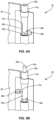
- Figures 9A and 9B illustrate the lock 40 moving between the disengaged position ( Figure 9A ) and the engaged position ( Figure 9B ) to secure the barrier door 20.
- Figures 9A and 9B illustrate the movement of the first pin 43a with the understanding that the second pin 43b operates in a similar manner.
- the person grasps the handle 48a and applies a force downward away from the end 45a of the cylinder 41a. The force overcomes the force of the biasing member and moves the pin 43a along the second section 47a of the opening 42a.
- the handle 48a is aligned with the first section 46a, the person applies a sideways force to move the handle 48a into the first section 46a. The person then releases the handle 48a as the force of the biasing member contacts the handle 48a against the outer edge of the first section 46a to maintain the position.
- the one or more handles 48 are accessible from just one side of the barrier door 20.
- the handles 48 are positioned on the front side 21 of the barrier door 20 to be accessible to the flight personnel in the vestibule 120 and/or flight deck 110. This positioning also prevents access to a person from the passenger section 121 as the handles 48 are not accessible from the rear side 22.
- the release mechanism 50 provides for moving the pins 43a, 43b (and elongated members 41a, 41b) inward to the disengaged position without using the handles 48.
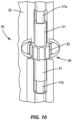
- the release mechanism 50 includes a sleeve 51 that is threaded onto the cylinders 41a, 41b. Rotation of the sleeve 51 relative to the elongated members 41a, 41b causes the elongated members 41a, 41b to retract inward into the sleeve 51. This movement causes the pins 43a, 43b to also retract inward towards and/or into the body 30 and disengage from the aircraft structure.
- the sleeve 51 includes a knob 52 with raised edges that facilitate grasping and applying a force by the user.
- the threads on the outer ends of the sleeve 51 are opposite one another. This provides for rotation of the sleeve 51 in one direction to cause retraction of both of the elongated members 41a, 41b. Likewise, rotation in the other direction causes extensions of both of the elongated members 41a, 41b.
- the sleeve 51 is accessible from both the front side 21 and the rear side 22 of the barrier door 20.
- the body 30 includes an opening 39 sized for the knob 52. This positioning provides for the knob 52 to be used from both sides of the barrier door 20. This provides for flight personnel in the vestibule 120 and/or flight deck 110 to unlock the barrier door 20, such as if one or both pins 43a, 43b are stuck in an extended position. This also provides for a passenger in the passenger section 121 to unlock the barrier door 20 in the event of an emergency in which they need to pass through the opening 113.
- the sleeve 51 of the release mechanism 50 is just accessible from a single side of the barrier door 20.
- the barrier door 20 functions to slow the movement of a person through the opening 113.
- the sleeve 51 is threaded such that it takes an extended time (e.g. 10-20 seconds) to rotate the sleeve 51 and disengage the one or more pins 43. This time provides for flight personnel to close and lock the flight deck door 90 and prevent the person from entering the flight deck 110.
- the one or more pins 43 contact against the aircraft structure in the engaged position. This can include extending into corresponding holes in the aircraft structure, such as in the floor 107 and ceiling 108. In other examples, the one or more pins 43 simply contact against the structure without extending into holes.
- a receptacle 60 is mounted to the aircraft structure to receive the pin 43. As illustrated in Figures 11A and 11B , the receptacle 60 includes a body 61 and a flange 62. When mounted to the aircraft structure, the body 61 is recessed into the structure and the flange 62 extends along the surface. An opening 63 extends through the flange 62 and into the body 61 to receive the pin 43.
- a plug 64 is mounted in the opening 63 and biased outward by a biasing member 65.
- the pin 43 In the engaged position, the pin 43 extends into the opening 63 and contacts against the plug 64. The force of the pin 43 moves the plug 64 against the biasing member 65 and further into the body 61.
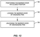
- Figure 12 illustrates a method of controlling movement of passengers through an opening 113 within a cabin area 103 of an aircraft 100.
- the barrier door 20 is positioned in a closed position that extends across the opening 113 (block 190). In some examples, this occurs prior to opening the flight deck door 90. While in the closed position, the barrier door 20 is locked by moving a first pin 43a and a second pin 43b that are each connected to the barrier door 20 to engaged positions (block 192).
- unlocking the barrier door 20 includes flight personnel grasping the handle 48 on each pin 43 and sliding the pin 43 inward and disengaging the pin 43 from the aircraft structure.
- Figure 13 illustrates a method of controlling movement of passengers through an opening 113 within a cabin area 103 of an aircraft 100.
- this method occurs when one or more of the pins 43 get suck or jammed and the barrier door 20 cannot be opened in a straight-forward manner (such as the method disclosed in Figure 12 ).
- This method may also occur when a person in the passenger section 121 needs access to the other side of the barrier door 20 such as access to the vestibule 120 or flight deck 110. This may occur in the event of a medical emergency or if an unauthorized person is forward of the barrier door 20.
- the barrier door 20 is positioned in a closed position that extends across the opening 113 (block 200).
- a sleeve 51 that is connected to the body 30 is rotated which retracts the first pin 43a and disengages the first pin 43a from the ceiling 108 and simultaneously retracts the second pin 43b and disengages the second pin 43b from the floor 107 (block 204). While the first pin 43a and the second pin 43b are disengaged, the barrier door 20 is positioned in an open position that opens the opening 113 (block 206).
- the biasing members 44, 65 are springs. In other examples, the biasing members are a foam block or other flexible material that applies an outward force.
Landscapes
- Engineering & Computer Science (AREA)
- Aviation & Aerospace Engineering (AREA)
- Mechanical Engineering (AREA)
- Lock And Its Accessories (AREA)
- Specific Sealing Or Ventilating Devices For Doors And Windows (AREA)
- Body Structure For Vehicles (AREA)
Abstract
Description
- The present disclosure relates generally to the field of barriers and, more specifically, to barrier doors configured to be used within an aircraft.
- Aircraft have a flight deck that includes flight instruments, instrument panels, and various controls that enable the flight personnel to operate the aircraft. The flight deck is positioned towards the front of the aircraft and is usually a separate compartment away from the cabin area where passengers sit during flight. A flight deck door further separates the flight deck from the cabin area.
- The flight deck door is closed and locked during flight. This allows the flight personnel to concentrate on operating the aircraft and prevents entry of unwanted persons onto the flight deck. However, the flight deck door may be opened during flight for various reasons. One occurrence is when the flight personnel use the lavatory which is located in the cabin area of the aircraft. Other occurrences are when food and/or drinks that are prepared in the galley of the cabin area are delivered to the flight personnel on the flight deck, and when flight personnel leave the flight deck during a break.
- Opening of the flight deck door could present an opportunity for an unwanted person to gain entry to the flight deck. The unwanted person could suddenly rush the front of the aircraft once the flight deck door is opened and force their way into the flight deck. It would be difficult for flight personnel working in the cabin area to react to this movement in a fast enough manner to close and lock the flight deck door.
- A device is needed that would inhibit a person in the cabin area from rushing towards the flight deck. The device would prevent the person from reaching the front of the aircraft or would slow their movement such that the flight deck door could be closed and locked prior to the person reaching the flight deck.
- One aspect is directed to a barrier door to control movement of persons through an opening within a cabin area of an aircraft. The barrier door comprises a body comprising an upper side, a lower side, and lateral sides. A lock is connected to the body and comprises a cylinder with an elongated shape comprising an inner end and an outer end and an interior space that is hollow, a pin positioned within the interior space of the cylinder and movable between a disengaged position with a distal end retracted within the interior space and an engaged position with the distal end extending outward beyond the outer end of the cylinder, a biasing member that biases the pin towards the engaged position, and a release mechanism threaded to the inner end of the cylinder with the release mechanism rotatable relative to the cylinder to adjust a position of the cylinder and pin relative to the body.
- In another aspect, the outer end of the cylinder is aligned with the upper side of the body for the pin to extend outward beyond the body in the engaged position.
- In another aspect, a handle extends outward from the pin and an opening in the cylinder is in communication with the interior space with the opening comprising a first section and a second section and the handle is in the first section of the opening when the pin is in the disengaged position and in the second section of the opening when the pin is in the engaged position.
- In another aspect, the body comprises a first side and a second side and the handle extends outward beyond the first side of the body and is positioned away from the second side of the body.
- In another aspect, an opening is in the body and the release mechanism comprises a sleeve with the sleeve positioned in the opening and the sleeve is accessible from both the first side of the body and the second side of the body.
- In another aspect, the release mechanism comprises a sleeve that extends around the inner end of the cylinder with the sleeve comprising interior threads and the cylinder comprising exterior threads.
- In another aspect, a receptacle is configured to be mounted in proximity to the body with the receptacle comprising a biased plug sized to contact against the distal end of the pin when the pin is in the engaged position.
- In another aspect, the body comprises a plurality of vertical slats that are hingedly connected together with the barrier door movable between an open position with the vertical slats in a folded configuration and a closed position with the vertical slats in an unfolded configuration.
- In another aspect, the pin is fixedly positioned relative to the cylinder during rotation of the release mechanism.
- One aspect is directed to a barrier door to control movement of persons through an opening within a cabin area of an aircraft. The barrier door comprises a body comprising an outer perimeter. A sleeve is connected to the body. A first elongated member is connected to and extends outward from the sleeve in a first direction. A second elongated member is connected to and extends outward from the sleeve in a second direction. A first pin is connected to the first elongated member and a second pin is connected to the second elongated member. The first pin and the second pin are movable between retracted positions that are inward within the outer perimeter of the body and extended positions that are outward beyond the outer perimeter of the body. The sleeve is rotatable relative to the first elongated member and the second elongated member to move both of the first pin and the second pin inward within the outer perimeter of the body in the extended positions.
- In another aspect, each of the first elongated member and the second elongated member are cylinders with a hollow interior space and the first pin is positioned within the first elongated member and the second pin is positioned within the second elongated member.
- In another aspect, the sleeve is positioned along a central section of the body and the first elongated member extends outward towards an upper side of the body with the first pin extending outward beyond the upper side of the body in the extended position.
- In another aspect, the second elongated member extends outward towards a lower side of the body with the second pin extending outward beyond the lower side of the body in the extended position.
- In another aspect, the first pin is fixedly positioned relative to the first elongated member during rotation of the sleeve and the second pin is fixedly positioned relative to the second elongated member during rotation of the sleeve.
- In another aspect, the sleeve, the first elongated member, and the second elongated member are aligned together and extend along a lateral side of the body.
- In another aspect, the sleeve is connected with threads to each of the first elongated member and the second elongated member.
- In another aspect, each of the first pin and the second pin comprise a main body with a proximal end and a distal end and a handle that extends outward from the main body between the proximal end of the distal end with the handle extending outward from the respective first elongated member and the second elongated member in the retracted position.
- One aspect is directed to a method of controlling movement of passengers through an opening within a cabin area of an aircraft. The method comprises: positioning a barrier door in a closed position that extends across the opening; while in the closed position, locking the barrier door by moving a first pin and a second pin that are each connected to the barrier door to engaged positions with the first pin extending outward beyond an upper side of a body of the barrier door and engaging the first pin with a ceiling of the aircraft and with the second pin extending outward beyond a lower side of the body and engaging the second pin with a floor of the aircraft; while the first pin and the second pin are in the engaged positions, rotating a sleeve that is connected to the body and retracting the first pin and disengaging the first pin from the ceiling and simultaneously retracting the second pin and disengaging the second pin from the floor; and while the first pin and the second pin are disengaged, positioning the barrier door in an open position that provides passage through the opening.
- In another aspect, the method further comprises moving the first pin within a first cylinder and extending a distal end of the first pin outward beyond the upper side of the body and engaging the ceiling and moving the second pin within a second cylinder and extending a distal end of the second pin outward beyond the lower side of the body and engaging the floor.
- In another aspect, the method further comprising maintaining a relative position between the first pin and the first cylinder and the second pin and the second cylinder while rotating the sleeve and retracting the first pin and the second pin.
- The features, functions and advantages that have been discussed can be achieved independently in various aspects or may be combined in yet other aspects, further details of which can be seen with reference to the following description and the drawings.
-
-
Figure 1 is a perspective view of an aircraft. -
Figure 2 is a top schematic view of an interior of the aircraft ofFigure 1 including the flight deck and the cabin area. -
Figure 3 is a perspective view of a flight deck door in a closed position. -
Figure 4 is a front view of a barrier door in a closed position. -
Figure 5 is a front view of the barrier door ofFigure 4 in an open position. -
Figure 6 is a front view of a barrier door. -
Figure 7 is a schematic section view of a lock. -
Figure 8 is a schematic section view of a lock. -
Figure 9A is a perspective view of a portion of a lock in a disengaged position. -
Figure 9B is a perspective view of a portion of the portion of the lock inFigure 9A in an engaged position. -
Figure 10 is a perspective view of a release mechanism of a lock. -
Figure 11A is a perspective view of a receptacle. -
Figure 11B is a schematic section view of the receptacle ofFigure 11A . -
Figure 12 is a flowchart diagram of a method of controlling movement of passengers through an opening within a cabin area of an aircraft. -
Figure 13 is a flowchart diagram of a method of controlling movement of passengers through an opening within a cabin area of an aircraft. -
Figures 1 and2 illustrate anaircraft 100 that includes afuselage 101. Aflight deck 110 is positioned at a front of thefuselage 101 and acabin area 103 is positioned rearward. Thecabin area 103 is equipped for accommodating passengers. The size of theflight deck 110 and thecabin area 103 can vary depending upon theaircraft 100. One or moreexterior doors 104 provide for passengers and the flight personnel to enter and exit thefuselage 101. - The
flight deck 110 includes one ormore seats 111 for the flight personnel including but not limited to the pilot, co-pilot, and other authorized persons. Various controls and instrument panels (not illustrated) are located for use by the pilot and co-pilot to control theaircraft 100. - The
cabin area 103 is positioned along thefuselage 101 rearward of theflight deck 110. Thecabin area 103 includes apassenger section 121 withseats 105 arranged in rows along one ormore aisles 106. In some examples such as a commercial airline, theseats 105 extend throughout thecabin area 103. In other examples in which theaircraft 100 is used for cargo transport, a limited number ofseats 105 are positioned in thecabin area 103. - The
cabin area 103 also includes avestibule 120 positioned between theflight deck 110 and thepassenger section 121. Thevestibule 120 includes one or more monuments 112 that are mounted to the structural members of theaircraft 100 within thefuselage 101. The monuments 112 are functional units with examples including but not limited to galleys, lavatories, and stowage units. In some examples, the monuments 112 are shaped and sized to extend from thefloor 107 to theceiling 108 of thecabin area 103. In some examples, the monuments 112 extend between awall 114 of thefuselage 101 to anaisle 106.Figure 2 includes thevestibule 120 including a pair ofgalley monuments lavatory monument 112c, and astowage monument 112d. - A
flight deck door 90 separates theflight deck 110 from thecabin area 103, and in some examples specifically separates theflight deck 110 from thevestibule 120. Theflight deck door 90 prevents unintended persons from entering theflight deck 110 from thecabin area 103. As illustrated inFigure 3 , theflight deck door 90 includes alock 91 configured to secure thedoor 90 in the closed position. Thelock 91 can include various configurations for unlocking, such as a magnetic card reader and input buttons. Aviewing hole 92 provides for the flight personnel on theflight deck 110 to see into thecabin area 103 without opening thedoor 90. In some examples, thedoor 90 is mounted in aframe 109 that mounts onto one or more of the monuments 112,floor 107, andceiling 108. - As illustrated in
Figure 2 , thecabin area 103 further includes anopening 113 in proximity to theflight deck 110. In this example, theopening 113 is formed between two monuments -galley monument 112b andlavatory monument 112c. Other examples include theopening 113 formed betweenmonuments opening 113 formed betweenmonuments opening 113 formed between various components, such as monuments 112,walls 114 of thefuselage 101, and seats 105. - A
barrier door 20 is positioned at theopening 113 and includes afront side 21 that faces towards the front of theaircraft 100 and an opposingrear side 22. Thebarrier door 20 is movable between an open position and a closed position (as illustrated inFigure 2 ). In the open position thebarrier door 20 is retracted or otherwise configured to allow people to pass through theopening 113, such as for passengers to use thelavatory 112c or flight personnel to move between theflight deck 110 andpassenger section 121. In the closed position, thebarrier door 20 extends across and is locked within theopening 113. In the closed position thebarrier door 20 functions to delay or otherwise slow the movement of a person moving from thepassenger section 121 towards theflight deck 110. This time provides for theflight deck door 90 to be closed and locked. -
Figure 4 schematically illustrates abarrier door 20 in a closed position. Thebarrier door 20 includes abody 30 sized to extend across theopening 113. Alock 40 that includes one or moreelongated members 41 is secured to thebody 30 and movable between engaged and disengaged positions. In the engaged position, the one or moreelongated members 41 extend outward and engage with the structure of theaircraft 100 to maintain thebarrier door 20 in the closed position. The structure of theaircraft 100 can include but is not limited to one or more of thefloor 107,ceiling 108, monument 112,seat 105,frame 109, andouter wall 114. Thelock 40 further includes arelease mechanism 50 that provides for moving the one or moreelongated members 41 to the disengaged position. In the disengaged position as illustrated inFigure 5 , the one or moreelongated members 41 are retracted away from the structure of theaircraft 100 to allow for thebarrier door 20 to move between the open and closed positions. - The
body 30 can include various shapes and sizes. In one example, thebody 30 in the closed position is rectangular and includes anupper side 31,lower side 32, andlateral sides opening 113. In some examples, thebody 30 is sized to completely fill theopening 113. In other examples, thebody 30 is smaller than theopening 113 with one or more gaps positioned between thebody 30 and the edges of theopening 113. In the open position, thebarrier door 20 is positioned to allow persons to move through theopening 113. In some examples as illustrated inFigure 5 , thebody 30 can fold or otherwise retract to fill a limited portion of theopening 113 and allow for persons to pass. In another example, thebody 30 is connected to the structure of the aircraft such as along one of the lateral sides and pivots on a hinge away from theopening 113. - The
body 30 can have a variety of different constructions. In some examples, thebody 30 is constructed as a single unitary piece, such as a large solid panel. In another example, thebody 30 is constructed from multiple different sections that are mounted together. The different sections can be fixedly positioned relative to one another or can be movable relative to each other.Figure 6 illustrates an example with thebody 30 formed byvertical slats 35 that are hingedly connected together. The lateral sides of theslats 35 are connected together to provide for pivoting movement. The connection between theslats 35 can include rods that extend along the height, or the lateral sides of theslats 35 can include fingers that engaged together and provide for the relative movement. - In some examples as illustrated in
Figure 6 , amount 36 is configured to mount thebody 30 in theopening 113. Themount 36 is positioned on thelateral side 33 and includespins lower sides ceiling 108 andfloor 107 respectively. In some examples, themount 36 provides for thebody 30 to be pivotally mounted in theopening 113. - The
lock 40 secures thedoor 20 in the closed position. Thelock 40 is attached to thebody 30 and can be positioned at various locations. In one example as illustrated inFigure 6 , thelock 40 is positioned along thelateral side 34 and configured to extend outward from one or both of theupper side 31 andlower side 32 in the engaged position. In other examples, thelock 40 is orientated horizontally across thebody 30 and configured to extend outward from one or both of the lateral sides 33, 34 in the engaged position. -
Figure 7 illustrates a schematic diagram of thelock 40 that includes anelongated member 41. Apin 43 is connected to theelongated member 41. In some examples as illustrated inFigure 7 , theelongated member 41 is a cylinder with a hollow interior space that houses thepin 43. In other examples, theelongated member 41 is a rod and thepin 43 is attached to an exterior of the rod. The pin includes an elongated shape with adistal end 49. Thepin 43 is biased outward by biasingmember 44. Thepin 43 includes ahandle 48 that extends outward through anopening 42 in theelongated member 41. In a disengaged position, thehandle 48 is positioned in afirst section 46 of theopening 42. Thehandle 48 abuts against the edge of thefirst section 46 which positions theend 49 of thepin 43 in a retracted position. In some examples, the retracted positions includes thedistal end 49 within theend 45 of theelongated member 41. In other examples, thedistal end 49 extends outward beyond thebody 30. In the engaged position as illustrated inFigure 7 , thepin 43 is rotated relative to theelongated member 41 to position thehandle 48 in thesecond section 47 of theopening 42. Thesecond section 47 extends closer to theend 45 of theelongated member 41. The force of the biasingmember 44 pushes thepin 43 outward until thehandle 48 contacts against the upper edge of thesecond section 47. This positioning causes thepin 43 to extend outward beyond theend 45 of theelongated member 41 and engage with the aircraft structure. - The
lock 40 also include arelease mechanism 50. Therelease mechanism 50 includes asleeve 51 that is threaded onto theelongated member 41. Thesleeve 51 is attached to thebody 30 and threaded onto theelongated member 41. Thesleeve 51 can rotate but does not move along an axial length of theelongated member 41. Therefore, rotation of thesleeve 51 in a first direction causes the elongated member 41 (and attached pin 43) to move in a first direction (e.g., retract inward relative to the body 30). Rotation in a second direction causes theelongated member 41 to move in a second direction (e.g., extend outward relative to the body 30). Thesleeve 51 can be rotated in the directions to move thelock 40 between the engaged and disengaged positions. -
Figure 8 illustrates alock 40 configured to engage with two opposing sections of the aircraft structure such as thefloor 107 andceiling 108. Thelock 40 includes a pair ofelongated members sleeve 51.Pins elongated member pins outer ends pins elongated members members -
Figures 9A and 9B illustrate thelock 40 moving between the disengaged position (Figure 9A ) and the engaged position (Figure 9B ) to secure thebarrier door 20.Figures 9A and 9B illustrate the movement of thefirst pin 43a with the understanding that thesecond pin 43b operates in a similar manner. - The
pin 43a includes ahandle 48a that extends outward from a main section that is positioned in the hollow interior space of theelongated member 41a. Further theelongated member 41a includes anopening 42a in communication with the interior space. The opening includes afirst section 46a and asecond section 47a. During use, thepin 43a is rotated relative to theelongated member 41a with thehandle 48a positioned in thefirst section 46a of anopening 42a. The biasingmember 44a (not illustrated inFigures 9A and 9B ) applies a force to thepin 43a to position thehandle 48a against an outer side of thefirst section 46a. This contact between thehandle 48a andfirst section 46a positions thepin 43a axially along theelongated member 41 with theend 49a retracted inward from theend 45a of theelongated member 41a. Thelock 40 is positioned on thebody 30 such that theelongated member 41a does not engage with the aircraft structure and thus thebarrier door 20 can move between the open and closed positions. - In the engaged position of
Figure 9B , a person such as a flight personnel, grasps thehandle 48a and rotates thepin 43a to move thehandle 48a into thesecond section 47a of theopening 42a. The outer side of thesecond section 47a is in closer proximity to theend 45a of theelongated member 41a. The force applied by the biasing member moves thepin 43a axially outward from theelongated member 41a. The extent of axial movement is controlled by the contact of thehandle 48a against the outer edge of thesecond section 47a. The extension of thepin 43a outward beyond theelongated member 41a and beyond thebody 30 provides for thepin 43a to engage with the aircraft structure and lock thebarrier door 20 in the closed position. - To move the
lock 40 back to the unlocked position, the person grasps thehandle 48a and applies a force downward away from theend 45a of thecylinder 41a. The force overcomes the force of the biasing member and moves thepin 43a along thesecond section 47a of theopening 42a. When thehandle 48a is aligned with thefirst section 46a, the person applies a sideways force to move thehandle 48a into thefirst section 46a. The person then releases thehandle 48a as the force of the biasing member contacts thehandle 48a against the outer edge of thefirst section 46a to maintain the position. - In some examples, the one or
more handles 48 are accessible from just one side of thebarrier door 20. Using the example ofFigure 2 , thehandles 48 are positioned on thefront side 21 of thebarrier door 20 to be accessible to the flight personnel in thevestibule 120 and/orflight deck 110. This positioning also prevents access to a person from thepassenger section 121 as thehandles 48 are not accessible from therear side 22. - The
release mechanism 50 provides for moving thepins elongated members handles 48. As illustrated inFigure 8 and10 , therelease mechanism 50 includes asleeve 51 that is threaded onto thecylinders sleeve 51 relative to theelongated members elongated members sleeve 51. This movement causes thepins body 30 and disengage from the aircraft structure. Thesleeve 51 includes aknob 52 with raised edges that facilitate grasping and applying a force by the user. - In some examples, the threads on the outer ends of the
sleeve 51 are opposite one another. This provides for rotation of thesleeve 51 in one direction to cause retraction of both of theelongated members elongated members - In some examples, the
sleeve 51 is accessible from both thefront side 21 and therear side 22 of thebarrier door 20. As illustrated inFigure 10 , thebody 30 includes anopening 39 sized for theknob 52. This positioning provides for theknob 52 to be used from both sides of thebarrier door 20. This provides for flight personnel in thevestibule 120 and/orflight deck 110 to unlock thebarrier door 20, such as if one or bothpins passenger section 121 to unlock thebarrier door 20 in the event of an emergency in which they need to pass through theopening 113. In other examples, thesleeve 51 of therelease mechanism 50 is just accessible from a single side of thebarrier door 20. - In some examples, the
barrier door 20 functions to slow the movement of a person through theopening 113. Thesleeve 51 is threaded such that it takes an extended time (e.g. 10-20 seconds) to rotate thesleeve 51 and disengage the one or more pins 43. This time provides for flight personnel to close and lock theflight deck door 90 and prevent the person from entering theflight deck 110. - In some examples, the one or
more pins 43 contact against the aircraft structure in the engaged position. This can include extending into corresponding holes in the aircraft structure, such as in thefloor 107 andceiling 108. In other examples, the one ormore pins 43 simply contact against the structure without extending into holes. In other examples, areceptacle 60 is mounted to the aircraft structure to receive thepin 43. As illustrated inFigures 11A and 11B , thereceptacle 60 includes abody 61 and aflange 62. When mounted to the aircraft structure, thebody 61 is recessed into the structure and theflange 62 extends along the surface. Anopening 63 extends through theflange 62 and into thebody 61 to receive thepin 43. Aplug 64 is mounted in theopening 63 and biased outward by a biasingmember 65. In the engaged position, thepin 43 extends into theopening 63 and contacts against theplug 64. The force of thepin 43 moves theplug 64 against the biasingmember 65 and further into thebody 61. -
Figure 12 illustrates a method of controlling movement of passengers through anopening 113 within acabin area 103 of anaircraft 100. Thebarrier door 20 is positioned in a closed position that extends across the opening 113 (block 190). In some examples, this occurs prior to opening theflight deck door 90. While in the closed position, thebarrier door 20 is locked by moving afirst pin 43a and asecond pin 43b that are each connected to thebarrier door 20 to engaged positions (block 192). In some examples, locking thebarrier door 20 includes a person (e.g., flight personnel) grasping and rotating thefirst handle 48a from thefirst section 46a to thesecond section 47a of theopening 42a and extending thefirst pin 43a outward beyond anupper side 31 of abody 30 of thebarrier door 20 and engaging thefirst pin 43a with aceiling 108. The person also grasps and rotates thesecond handle 48b and rotates the pin in a similar manner to extend thesecond pin 43b outward beyond alower side 32 of thebody 30 and into engagement with afloor 107 of the aircraft. In some examples, locking thebarrier door 20 includes positioning just asingle pin 43 into engagement with the aircraft structure. Thebarrier door 20 remains in the closed position allowing for theflight deck door 90 to be opened. After theflight deck door 90 is closed, thebarrier door 20 is unlocked and moved to the open position (block 194). In some examples, unlocking thebarrier door 20 includes flight personnel grasping thehandle 48 on eachpin 43 and sliding thepin 43 inward and disengaging thepin 43 from the aircraft structure. -
Figure 13 illustrates a method of controlling movement of passengers through anopening 113 within acabin area 103 of anaircraft 100. In some examples, this method occurs when one or more of thepins 43 get suck or jammed and thebarrier door 20 cannot be opened in a straight-forward manner (such as the method disclosed inFigure 12 ). This method may also occur when a person in thepassenger section 121 needs access to the other side of thebarrier door 20 such as access to thevestibule 120 orflight deck 110. This may occur in the event of a medical emergency or if an unauthorized person is forward of thebarrier door 20. In this method, thebarrier door 20 is positioned in a closed position that extends across the opening 113 (block 200). While in the closed position, thebarrier door 20 is locked by moving afirst pin 43a and asecond pin 43b that are each connected to thebarrier door 20 to engaged positions (block 202). In some examples, the engaged positions include thefirst pin 43a extending outward beyond anupper side 31 of abody 30 of thebarrier door 20 and engaging thefirst pin 43a with aceiling 108 of the aircraft and with thesecond pin 43b extending outward beyond alower side 32 of thebody 30 and engaging thesecond pin 43b with afloor 107 of the aircraft. In some examples, locking thebarrier door 20 includes engaging just asingle pin 43. While thebarrier door 20 is locked with thepins sleeve 51 that is connected to thebody 30 is rotated which retracts thefirst pin 43a and disengages thefirst pin 43a from theceiling 108 and simultaneously retracts thesecond pin 43b and disengages thesecond pin 43b from the floor 107 (block 204). While thefirst pin 43a and thesecond pin 43b are disengaged, thebarrier door 20 is positioned in an open position that opens the opening 113 (block 206). - In some examples, the biasing
members - The present invention may be carried out in other ways than those specifically set forth herein without departing from essential characteristics of the invention. The present embodiments are to be considered in all respects as illustrative and not restrictive, and all changes coming within the meaning and equivalency range of the appended claims are intended to be embraced therein.
- Illustrative, non-exclusive examples of inventive subject matter according to the present disclosure are described in the following enumerated paragraphs:
- Clause 1: A barrier door to control movement of persons through an opening within a cabin area of an aircraft, the barrier door comprising:
- a
body 30 comprising anupper side 31, alower side 32, andlateral sides - a
lock 40 connected to thebody 30, thelock 40 comprising:- a
cylinder 41 with an elongated shape comprising an inner end and an outer end, thecylinder 41 further comprising an interior space that is hollow; - a
pin 43 positioned within the interior space of the cylinder and movable between a disengaged position with a distal end retracted within the interior space and an engaged position with the distal end extending outward beyond the outer end of thecylinder 41; - a biasing
member 44 that biases thepin 43 towards the engaged position; and - a
release mechanism 50 threaded to the inner end of thecylinder 41, therelease mechanism 50 rotatable relative to thecylinder 41 to adjust a position of thecylinder 41 andpin 43 relative to thebody 30.
- a
- a
- Clause 2: The barrier door of Clause 1, wherein the outer end of the
cylinder 41 is aligned with theupper side 31 of thebody 30 for thepin 43 to extend outward beyond thebody 30 in the engaged position. - Clause 3: The barrier door of Clause 1, further comprising:
- a
handle 48 that extends outward from thepin 43; - an opening in the
cylinder 41 that is in communication with the interior space, the opening comprising afirst section 46 and asecond section 47; and - wherein the
handle 48 is in thefirst section 46 of the opening when thepin 43 is in the disengaged position and in thesecond section 47 of the opening when thepin 43 is in the engaged position.
- a
- Clause 4: The barrier door of Clause 3, wherein the
body 30 comprises afirst side 21 and asecond side 22, wherein thehandle 48 extends outward beyond thefirst side 21 of thebody 30 and is positioned away from thesecond side 22 of thebody 30. - Clause 5: The barrier door of Clause 4, further comprising:
- an
opening 39 in thebody 30; - the
release mechanism 50 comprises asleeve 51; and - wherein the
sleeve 51 is positioned in theopening 39 and thesleeve 51 is accessible from both thefirst side 21 of thebody 30 and thesecond side 22 of thebody 30.
- an
- Clause 6: The barrier door of Clause 1, wherein the
release mechanism 50 comprises asleeve 51 that extends around the inner end of thecylinder 41, thesleeve 51 comprising interior threads and thecylinder 41 comprising exterior threads. - Clause 7: The barrier door of Clause 1, further comprising a
receptacle 60 configured to be mounted in proximity to thebody 30, thereceptacle 60 comprising a biased plug sized to contact against the distal end of thepin 43 when thepin 43 is in the engaged position. - Clause 8: The barrier door of Clause 1, wherein the
body 30 comprises a plurality ofvertical slats 35 that are hingedly connected together, thebarrier door 20 movable between an open position with thevertical slats 35 in a folded configuration and a closed position with thevertical slats 35 in an unfolded configuration. - Clause 9: The barrier door of Clause 1, wherein the
pin 43 is fixedly positioned relative to thecylinder 41 during rotation of therelease mechanism 50. - Clause 10: A barrier door to control movement of persons through an opening within a cabin area of an aircraft, the barrier door comprising:
- a
body 30 comprising an outer perimeter; - a
sleeve 51 connected to thebody 30; - a first
elongated member 41a connected to and extending outward from thesleeve 51 in a first direction; - a second
elongated member 41b connected to and extending outward from thesleeve 51 in a second direction; - a
first pin 43a connected to the firstelongated member 41a and asecond pin 43b connected to the secondelongated member 41b, thefirst pin 43a and thesecond pin 43b movable between retracted positions that are inward within the outer perimeter of thebody 30 and extended positions that are outward beyond the outer perimeter of thebody 30; and - wherein the
sleeve 51 is rotatable relative to the firstelongated member 41a and the secondelongated member 41b to move both of thefirst pin 43a and thesecond pin 43b inward within the outer perimeter of thebody 30 in the extended positions.
- a
- Clause 11: The barrier door of Clause 10, wherein each of the first
elongated member 41a and the secondelongated member 41b are cylinders with a hollow interior space and thefirst pin 43a is positioned within the firstelongated member 41a and thesecond pin 43b is positioned within the secondelongated member 41b. - Clause 12: The barrier door of Clause 10, wherein the
sleeve 51 is positioned along a central section of thebody 30 and the firstelongated member 41a extends outward towards an upper side of thebody 30 with thefirst pin 43a extending outward beyond theupper side 31 of thebody 30 in the extended position. - Clause 13: The barrier door of Clause 12, wherein the second
elongated member 41b extends outward towards alower side 32 of thebody 30 with thesecond pin 43b extending outward beyond thelower side 32 of thebody 30 in the extended position. - Clause 14: The barrier door of Clause 10, wherein the
first pin 43a is fixedly positioned relative to the firstelongated member 41a during rotation of thesleeve 51 and thesecond pin 43b is fixedly positioned relative to the secondelongated member 41b during rotation of thesleeve 51. - Clause 15: The barrier door of Clause 10, wherein the
sleeve 51, the firstelongated member 41a, and the secondelongated member 41b are aligned together and extend along alateral side 34 of thebody 30. - Clause 16: The barrier door of Clause 10, wherein the
sleeve 51 is connected with threads to each of the firstelongated member 41a and the secondelongated member 41b. - Clause 17: The barrier door of Clause 10, wherein each of the
first pin 43a and thesecond pin 43b comprise a main body with a proximal end and a distal end and ahandle 48 that extends outward from the main body between the proximal end of the distal end with thehandle 48 extending outward from the respective firstelongated member 41a and the secondelongated member 41b in the retracted position. - Clause 18: A method of controlling movement of passengers through an opening within a cabin area of an aircraft, the method comprising:
- positioning a
barrier door 20 in a closed position that extends across theopening 113; - while in the closed position, locking the
barrier door 20 by moving afirst pin 43a and asecond pin 43b that are each connected to thebarrier door 20 to engaged positions with thefirst pin 43a extending outward beyond anupper side 31 of abody 30 of thebarrier door 20 and engaging thefirst pin 43a with aceiling 108 of the aircraft and with thesecond pin 43b extending outward beyond alower side 32 of thebody 30 and engaging thesecond pin 43b with afloor 107 of the aircraft; - while the
first pin 43a and thesecond pin 43b are in the engaged positions, rotating asleeve 51 that is connected to thebody 30 and retracting thefirst pin 43a and disengaging thefirst pin 43a from theceiling 108 and simultaneously retracting thesecond pin 43b and disengaging thesecond pin 43b from thefloor 107; and - while the
first pin 43a and thesecond pin 43b are disengaged, positioning thebarrier door 20 in an open position that provides passage through theopening 113.
- positioning a
- Clause 19: The method of Clause 18, further comprising moving the
first pin 43a within afirst cylinder 41a and extending a distal end of thefirst pin 43a outward beyond theupper side 31 of thebody 30 and engaging theceiling 108 and moving thesecond pin 43b within asecond cylinder 41b and extending a distal end of thesecond pin 43b outward beyond thelower side 32 of thebody 30 and engaging thefloor 107. - Clause 20: The method of Clause 19, further comprising maintaining a relative position between the
first pin 43a and thefirst cylinder 41a and thesecond pin 43b and thesecond cylinder 41b while rotating thesleeve 51 and retracting thefirst pin 43a and thesecond pin 43b.
Claims (15)
- A barrier door (20) to control movement of persons through an opening (113) within a cabin area (103) of an aircraft (100), the barrier door (20) comprising:a body (30) comprising an upper side (31), a lower side (32), and lateral sides (33, 34);a lock (40) connected to the body (30), the lock (40) comprising:a cylinder (41) with an elongated shape comprising an inner end and an outer end, the cylinder (41) further comprising an interior space that is hollow;a pin (43) positioned within the interior space of the cylinder (41) and movable between a disengaged position with a distal end (49) retracted within the interior space and an engaged position with the distal end (49) extending outward beyond the outer end of the cylinder (41);a biasing member (44) that biases the pin (43) towards the engaged position; anda release mechanism (50) threaded to the inner end of the cylinder (41), the release mechanism (50) rotatable relative to the cylinder (41) to adjust a position of the cylinder (41) and pin (43) relative to the body (30).
- The barrier door (20) of claim 1, wherein the outer end of the cylinder (41) is aligned with the upper side (31) of the body (30) for the pin (43) to extend outward beyond the body (30) in the engaged position.
- The barrier door (20) of claim 1 or 2, further comprising:a handle (48) that extends outward from the pin (43);an opening (42) in the cylinder (41) that is in communication with the interior space, the opening (42) comprising a first section (46) and a second section (47); andwherein the handle (48) is in the first section (46) of the opening (42) when the pin (43) is in the disengaged position and in the second section (47) of the opening (42) when the pin (43) is in the engaged position.
- The barrier door (20) of claim 3, wherein the body (30) comprises a first side (21) and a second side (22), wherein the handle (48) extends outward beyond the first side (21) of the body (30) and is positioned away from the second side (22) of the body (30).
- The barrier door (20) of claim 4, further comprising:an opening (39) in the body (30);the release mechanism (50) comprises a sleeve (51); andwherein the sleeve (51) is positioned in the opening (39) and the sleeve (51) is accessible from both the first side (21) of the body (30) and the second side (22) of the body (30).
- The barrier door (20) of any one of claims 1 to 4, wherein the release mechanism (50) comprises a sleeve (51) that extends around the inner end of the cylinder (41), the sleeve (51) comprising interior threads and the cylinder (41) comprising exterior threads.
- The barrier door (20) of any one of claims 1 to 6, further comprising a receptacle (60) configured to be mounted in proximity to the body (30), the receptacle (60) comprising a biased plug sized to contact against the distal end (49) of the pin (43) when the pin (43) is in the engaged position.
- The barrier door (20) of any one of claims 1 to 7, wherein the pin (43) is fixedly positioned relative to the cylinder (41) during rotation of the release mechanism (50).
- The barrier door (20) of claim 1, wherein :the release mechanism (50) comprises a sleeve (51) connected to the body (30);wherein the cylinder (41) is a first elongated member (41a) connected to and extending outward from the sleeve (51) in a first direction; andthe barrier door (20) further comprises a second elongated member (41b) connected to and extending outward from the sleeve (51) in a second direction, and a second pin (43b);wherein the pin (43) is a first pin (43a) connected to the first elongated member (41a) and the second pin (43b) connected to the second elongated member (41b), the first pin (43a) and the second pin (43b) movable between retracted positions that are inward within an outer perimeter of the body (30) and extended positions that are outward beyond the outer perimeter of the body (30); andwherein the sleeve (51) is rotatable relative to the first elongated member (41a) and the second elongated member (41b) to move both of the first pin (43a) and the second pin (43b) inward within the outer perimeter of the body (30) in the extended positions.
- The barrier door (20) of claim 9, wherein each of the first elongated member (41a) and the second elongated member (41b) are cylinders with a hollow interior space and the first pin (43a) is positioned within the first elongated member (41a) and the second pin (43b) is positioned within the second elongated member (41b).
- The barrier door (20) of claim 9 or 10, wherein the sleeve (51) is positioned along a central section of the body (30) and the first elongated member (41a) extends outward towards the upper side (31) of the body (30) with the first pin (43a) extending outward beyond the upper side (31) of the body (30) in the extended position.
- The barrier door (20) of claim 11, wherein the second elongated member (41b) extends outward towards the lower side (32) of the body (30) with the second pin (43b) extending outward beyond the lower side (32) of the body (30) in the extended position.
- The barrier door (20) of any one of claims 9 to 12, wherein the first pin (43a) is fixedly positioned relative to the first elongated member (41a) during rotation of the sleeve (51) and the second pin (43b) is fixedly positioned relative to the second elongated member (41b) during rotation of the sleeve (51).
- The barrier door (20) of any one of claims 9 to 13, wherein the sleeve (51), the first elongated member (41a), and the second elongated member (41b) are aligned together and extend along the lateral side (34) of the body (30).
- A method of controlling movement of passengers through an opening (113) within a cabin area (103) of an aircraft (100), the method comprising:positioning a barrier door (20) in a closed position that extends across the opening (113);while in the closed position, locking the barrier door (20) by moving a first pin (43a) and a second pin (43b) that are each connected to the barrier door (20) to engaged positions with the first pin (43a) extending outward beyond an upper side (31) of a body (30) of the barrier door (20) and engaging the first pin (43a) with a ceiling (108) of the aircraft (100) and with the second pin (43b) extending outward beyond a lower side (32) of the body (30) and engaging the second pin (43b) with a floor (107) of the aircraft (100);while the first pin (43a) and the second pin (43b) are in the engaged positions, rotating a sleeve (51) that is connected to the body (30) and retracting the first pin (43a) and disengaging the first pin (43a) from the ceiling (108) and simultaneously retracting the second pin (43b) and disengaging the second pin (43b) from the floor (107); andwhile the first pin (43a) and the second pin (43b) are disengaged, positioning the barrier door (20) in an open position that provides passage through the opening (113).
Applications Claiming Priority (1)
| Application Number | Priority Date | Filing Date | Title |
|---|---|---|---|
| US18/336,106 US12227282B2 (en) | 2023-06-16 | 2023-06-16 | Barrier door for an aircraft |
Publications (2)
| Publication Number | Publication Date |
|---|---|
| EP4477529A1 true EP4477529A1 (en) | 2024-12-18 |
| EP4477529B1 EP4477529B1 (en) | 2026-05-13 |
Family
ID=90468843
Family Applications (1)
| Application Number | Title | Priority Date | Filing Date |
|---|---|---|---|
| EP24165860.8A Active EP4477529B1 (en) | 2023-06-16 | 2024-03-25 | Barrier door for an aircraft |
Country Status (4)
| Country | Link |
|---|---|
| US (1) | US12227282B2 (en) |
| EP (1) | EP4477529B1 (en) |
| JP (1) | JP2025000582A (en) |
| CN (1) | CN119142504A (en) |
Families Citing this family (1)
| Publication number | Priority date | Publication date | Assignee | Title |
|---|---|---|---|---|
| US20250304235A1 (en) * | 2024-03-28 | 2025-10-02 | The Boeing Company | Door Assembly with an Engagement Assembly |
Citations (8)
| Publication number | Priority date | Publication date | Assignee | Title |
|---|---|---|---|---|
| US5285596A (en) * | 1992-11-13 | 1994-02-15 | Kinsey Kenneth M | Door closure apparatus |
| GB2307712A (en) * | 1995-11-30 | 1997-06-04 | Chen Fu Hsiang | Memory metal latch device |
| US6783098B1 (en) * | 2003-05-15 | 2004-08-31 | Victor J. Chavez | Anti-hijacking security device, kit and method |
| US20160083092A1 (en) * | 2014-03-27 | 2016-03-24 | C&D Zodiac, Inc. | Bi-fold door module |
| US9428940B1 (en) * | 2015-06-05 | 2016-08-30 | Clarence E. Patrick | Three-way door latch |
| US20180265216A1 (en) * | 2017-03-17 | 2018-09-20 | The Boeing Company | Secondary flight deck door privacy/barrier panel system |
| US20200115029A1 (en) * | 2018-02-08 | 2020-04-16 | The Boeing Company | Aircraft Privacy Door and Door Frame Assembly |
| CN212614220U (en) * | 2020-05-11 | 2021-02-26 | 隆孝前 | Automatic head of bolt lock |
Family Cites Families (12)
| Publication number | Priority date | Publication date | Assignee | Title |
|---|---|---|---|---|
| US20030047648A1 (en) * | 2001-09-12 | 2003-03-13 | Batt Richard R. | Secure cockpit system |
| EP1427904B1 (en) * | 2001-09-16 | 2006-04-19 | Mul-T-Lock Security Products Ltd. | Access apparatus for a cockpit of an aircraft |
| US6663046B2 (en) * | 2001-10-25 | 2003-12-16 | Mark Bogdan Raczkowski | Safety system for cockpit |
| DE102011009481A1 (en) * | 2011-01-26 | 2012-07-26 | Airbus Operations Gmbh | Door arrangement with two door leaves |
| EP2796370B1 (en) | 2013-04-23 | 2019-03-13 | Airbus Operations GmbH | Double cabin attendant seat |
| DE102013110500A1 (en) | 2013-09-23 | 2015-04-16 | Airbus Operations Gmbh | Apparatus for supporting a vehicle attendant seat in a cabin of a vehicle, cabin assembly in a vehicle and vehicle having at least one cabin assembly |
| EP3248873B1 (en) | 2016-05-24 | 2022-02-09 | Airbus Operations GmbH | Aircraft monument, aircraft galley, aircraft, and method of operating an aircraft monument |
| CN109996912B (en) | 2016-11-28 | 2021-10-29 | 格兰博格国际有限公司 | Three-dimensional 3D knitted fabric and its manufacturing method |
| US11279461B2 (en) | 2017-06-01 | 2022-03-22 | The Boeing Company | Flight deck barrier door, aircraft comprising flight deck barrier door, and method of using flight deck barrier door |
| US11305860B2 (en) * | 2018-02-08 | 2022-04-19 | The Boeing Company | Aircraft privacy door and door frame assembly |
| US11124299B2 (en) | 2018-04-10 | 2021-09-21 | Rockwell Collins, Inc. | Multi-mode transformable monuments for aircraft doorway spaces |
| EP3741676B1 (en) | 2019-05-23 | 2021-12-08 | Rockwell Collins, Inc. | Multimode transformable monument |
-
2023
- 2023-06-16 US US18/336,106 patent/US12227282B2/en active Active
-
2024
- 2024-03-25 EP EP24165860.8A patent/EP4477529B1/en active Active
- 2024-06-14 CN CN202410770167.XA patent/CN119142504A/en active Pending
- 2024-06-17 JP JP2024097153A patent/JP2025000582A/en active Pending
Patent Citations (8)
| Publication number | Priority date | Publication date | Assignee | Title |
|---|---|---|---|---|
| US5285596A (en) * | 1992-11-13 | 1994-02-15 | Kinsey Kenneth M | Door closure apparatus |
| GB2307712A (en) * | 1995-11-30 | 1997-06-04 | Chen Fu Hsiang | Memory metal latch device |
| US6783098B1 (en) * | 2003-05-15 | 2004-08-31 | Victor J. Chavez | Anti-hijacking security device, kit and method |
| US20160083092A1 (en) * | 2014-03-27 | 2016-03-24 | C&D Zodiac, Inc. | Bi-fold door module |
| US9428940B1 (en) * | 2015-06-05 | 2016-08-30 | Clarence E. Patrick | Three-way door latch |
| US20180265216A1 (en) * | 2017-03-17 | 2018-09-20 | The Boeing Company | Secondary flight deck door privacy/barrier panel system |
| US20200115029A1 (en) * | 2018-02-08 | 2020-04-16 | The Boeing Company | Aircraft Privacy Door and Door Frame Assembly |
| CN212614220U (en) * | 2020-05-11 | 2021-02-26 | 隆孝前 | Automatic head of bolt lock |
Also Published As
| Publication number | Publication date |
|---|---|
| JP2025000582A (en) | 2025-01-07 |
| US12227282B2 (en) | 2025-02-18 |
| US20240417056A1 (en) | 2024-12-19 |
| EP4477529B1 (en) | 2026-05-13 |
| CN119142504A (en) | 2024-12-17 |
Similar Documents
| Publication | Publication Date | Title |
|---|---|---|
| DE102007051802B4 (en) | Stay module with an emergency exit hatch for an aircraft | |
| CN106163918B (en) | Holding system for movable member | |
| US9340293B2 (en) | Aircraft flight deck comprising a folding seat | |
| RU2677163C2 (en) | Module for airplane with seat fixed to door | |
| EP1698552B1 (en) | Arrangement of first and second parts | |
| EP4534408A1 (en) | Barrier center latch with delayed over-ride feature | |
| US9340294B1 (en) | Aircraft cabin egress | |
| EP4582338A1 (en) | Bi-fold barrier system and method for a flight deck of an aircraft | |
| US11958609B2 (en) | Expandable aircraft lavatory apparatus, system, and method | |
| EP4477529B1 (en) | Barrier door for an aircraft | |
| EP4624322A1 (en) | Door assembly with an engagement assembly | |
| CN116635300B (en) | Seat unit provided with a retractable privacy shell | |
| US10314285B1 (en) | Platform and guide panel for aircraft cabin egress | |
| EP4279384B1 (en) | Convertible closet with articulating top shelf | |
| EP4477528A1 (en) | Barrier door for an aircraft | |
| EP4477544A1 (en) | Deployable attendant seat aircraft cabin barrier | |
| EP4461647A1 (en) | Wheelchair accessible airliner lavatory | |
| US20230373630A1 (en) | Support device for an aircraft cabin interior layout assembly, related assembly and method | |
| US12617532B2 (en) | Dual purpose lavatory barrier | |
| EP4538177A1 (en) | Barrier for an aircraft | |
| US20030136878A1 (en) | Method and apparatus for impeding unauthorized entry into the cockpit of an airplane | |
| EP4624320A1 (en) | Door assembly with an engagement mechanism | |
| US12559253B2 (en) | Telescoping secondary barrier system | |
| EP4624321A1 (en) | Barrier door with hinged lock | |
| CN120773921A (en) | Crewmember seat and vehicle |
Legal Events
| Date | Code | Title | Description |
|---|---|---|---|
| PUAI | Public reference made under article 153(3) epc to a published international application that has entered the european phase |
Free format text: ORIGINAL CODE: 0009012 |
|
| STAA | Information on the status of an ep patent application or granted ep patent |
Free format text: STATUS: THE APPLICATION HAS BEEN PUBLISHED |
|
| AK | Designated contracting states |
Kind code of ref document: A1 Designated state(s): AL AT BE BG CH CY CZ DE DK EE ES FI FR GB GR HR HU IE IS IT LI LT LU LV MC ME MK MT NL NO PL PT RO RS SE SI SK SM TR |
|
| STAA | Information on the status of an ep patent application or granted ep patent |
Free format text: STATUS: REQUEST FOR EXAMINATION WAS MADE |
|
| 17P | Request for examination filed |
Effective date: 20250521 |
|
| GRAP | Despatch of communication of intention to grant a patent |
Free format text: ORIGINAL CODE: EPIDOSNIGR1 |
|
| STAA | Information on the status of an ep patent application or granted ep patent |
Free format text: STATUS: GRANT OF PATENT IS INTENDED |
|
| RIC1 | Information provided on ipc code assigned before grant |
Ipc: B64C 1/14 20060101AFI20251119BHEP Ipc: B64D 45/00 20060101ALI20251119BHEP Ipc: E05C 9/04 20060101ALI20251119BHEP |
|
| INTG | Intention to grant announced |
Effective date: 20251203 |
|
| RIN1 | Information on inventor provided before grant (corrected) |
Inventor name: MUELLER, ANDREW WILLIAM Inventor name: SCHWITTERS, CHRISTOPHER |
|
| GRAS | Grant fee paid |
Free format text: ORIGINAL CODE: EPIDOSNIGR3 |
|
| P01 | Opt-out of the competence of the unified patent court (upc) registered |
Free format text: CASE NUMBER: UPC_APP_0008658_4477529/2026 Effective date: 20260304 |
|
| GRAA | (expected) grant |
Free format text: ORIGINAL CODE: 0009210 |
|
| STAA | Information on the status of an ep patent application or granted ep patent |
Free format text: STATUS: THE PATENT HAS BEEN GRANTED |
|
| AK | Designated contracting states |
Kind code of ref document: B1 Designated state(s): AL AT BE BG CH CY CZ DE DK EE ES FI FR GB GR HR HU IE IS IT LI LT LU LV MC ME MK MT NL NO PL PT RO RS SE SI SK SM TR |
|
| REG | Reference to a national code |
Ref country code: CH Ref legal event code: F10 Free format text: ST27 STATUS EVENT CODE: U-0-0-F10-F00 (AS PROVIDED BY THE NATIONAL OFFICE) Effective date: 20260513 |