EP4477498A1 - Underbody, skateboard chassis and vehicle - Google Patents
Underbody, skateboard chassis and vehicle Download PDFInfo
- Publication number
- EP4477498A1 EP4477498A1 EP23901757.7A EP23901757A EP4477498A1 EP 4477498 A1 EP4477498 A1 EP 4477498A1 EP 23901757 A EP23901757 A EP 23901757A EP 4477498 A1 EP4477498 A1 EP 4477498A1
- Authority
- EP
- European Patent Office
- Prior art keywords
- compartment
- vehicle body
- longitudinal
- transverse
- beams
- Prior art date
- Legal status (The legal status is an assumption and is not a legal conclusion. Google has not performed a legal analysis and makes no representation as to the accuracy of the status listed.)
- Pending
Links
Images

Classifications
-
- B—PERFORMING OPERATIONS; TRANSPORTING
- B62—LAND VEHICLES FOR TRAVELLING OTHERWISE THAN ON RAILS
- B62D—MOTOR VEHICLES; TRAILERS
- B62D21/00—Understructures, i.e. chassis frame on which a vehicle body may be mounted
- B62D21/15—Understructures, i.e. chassis frame on which a vehicle body may be mounted having impact absorbing means, e.g. a frame designed to permanently or temporarily change shape or dimension upon impact with another body
- B62D21/152—Front or rear frames
-
- B—PERFORMING OPERATIONS; TRANSPORTING
- B60—VEHICLES IN GENERAL
- B60K—ARRANGEMENT OR MOUNTING OF PROPULSION UNITS OR OF TRANSMISSIONS IN VEHICLES; ARRANGEMENT OR MOUNTING OF PLURAL DIVERSE PRIME-MOVERS IN VEHICLES; AUXILIARY DRIVES FOR VEHICLES; INSTRUMENTATION OR DASHBOARDS FOR VEHICLES; ARRANGEMENTS IN CONNECTION WITH COOLING, AIR INTAKE, GAS EXHAUST OR FUEL SUPPLY OF PROPULSION UNITS IN VEHICLES
- B60K1/00—Arrangement or mounting of electrical propulsion units
- B60K1/04—Arrangement or mounting of electrical propulsion units of the electric storage means for propulsion
-
- B—PERFORMING OPERATIONS; TRANSPORTING
- B62—LAND VEHICLES FOR TRAVELLING OTHERWISE THAN ON RAILS
- B62D—MOTOR VEHICLES; TRAILERS
- B62D21/00—Understructures, i.e. chassis frame on which a vehicle body may be mounted
- B62D21/09—Means for mounting load bearing surfaces
-
- B—PERFORMING OPERATIONS; TRANSPORTING
- B62—LAND VEHICLES FOR TRAVELLING OTHERWISE THAN ON RAILS
- B62D—MOTOR VEHICLES; TRAILERS
- B62D25/00—Superstructure or monocoque structure sub-units; Parts or details thereof not otherwise provided for
- B62D25/20—Floors or bottom sub-units
- B62D25/2009—Floors or bottom sub-units in connection with other superstructure subunits
-
- B—PERFORMING OPERATIONS; TRANSPORTING
- B62—LAND VEHICLES FOR TRAVELLING OTHERWISE THAN ON RAILS
- B62D—MOTOR VEHICLES; TRAILERS
- B62D27/00—Connections between superstructure or understructure sub-units
- B62D27/06—Connections between superstructure or understructure sub-units readily releasable
-
- B—PERFORMING OPERATIONS; TRANSPORTING
- B60—VEHICLES IN GENERAL
- B60K—ARRANGEMENT OR MOUNTING OF PROPULSION UNITS OR OF TRANSMISSIONS IN VEHICLES; ARRANGEMENT OR MOUNTING OF PLURAL DIVERSE PRIME-MOVERS IN VEHICLES; AUXILIARY DRIVES FOR VEHICLES; INSTRUMENTATION OR DASHBOARDS FOR VEHICLES; ARRANGEMENTS IN CONNECTION WITH COOLING, AIR INTAKE, GAS EXHAUST OR FUEL SUPPLY OF PROPULSION UNITS IN VEHICLES
- B60K1/00—Arrangement or mounting of electrical propulsion units
- B60K1/04—Arrangement or mounting of electrical propulsion units of the electric storage means for propulsion
- B60K2001/0405—Arrangement or mounting of electrical propulsion units of the electric storage means for propulsion characterised by their position
- B60K2001/0438—Arrangement under the floor
Definitions
- This application relates to the field of vehicle technologies, and in particular, to a lower vehicle body, a skateboard chassis, and a vehicle.
- This application provides a lower vehicle body, a skateboard chassis, and a vehicle, which can reduce the costs of vehicles.
- this application provides a lower vehicle body of a vehicle, including a front compartment, a energy compartment frame, and a rear compartment, where the energy compartment frame is configured for mounting battery cells, and the front compartment and the rear compartment are connected to two ends of the energy compartment frame, where at least one of the front compartment and the rear compartment is detachably connected to the energy compartment frame.
- At least one of the front compartment and the rear compartment is detachably connected to the energy compartment frame.
- both the front compartment and the rear compartment are detachably connected to the energy compartment frame.
- the front compartment and the rear compartment are configured as both detachably connected to the energy compartment frame.
- the lower vehicle body is divided into three detachable parts. During transportation and storage, these three parts can be transported and stored separately, which is extremely convenient, further reducing the costs of storage and transportation.
- At least one of the front compartment and the rear compartment is detachably connected to the energy compartment frame through fasteners.
- the front compartment and the rear compartment are connected through fasteners.
- this connection method offers higher structural strength, thereby improving the stability, reliability, and durability of the lower vehicle body.
- the energy compartment frame includes a floor, two first transverse beams oppositely arranged in the first direction, and two first longitudinal beams oppositely arranged in the second direction, where the first longitudinal beams connect the two first transverse beams; the floor, the two first transverse beams, and the two first longitudinal beams enclose an accommodating cavity for accommodating battery cells; and the first direction intersects with the second direction.
- the energy compartment frame is configured as including two first transverse beams and two first longitudinal beams, which together with the floor, define an accommodating space for accommodating battery cells. This configuration facilitates manufacturing and can create a large accommodating space.
- the front compartment and the rear compartment are detachably connected to two ends of the first longitudinal beam respectively.
- the front compartment and the rear compartment are configured as connected to the two ends of the first longitudinal beam respectively.
- the front compartment, the energy compartment frame, and the rear compartment are generally arranged in sequence in a longitudinal direction. Therefore, when compared with connecting to the first transverse beam, connecting to the first longitudinal beam extending along the longitudinal direction is more convenient.
- the first longitudinal beam generally has greater rigidity and strength, therefore, the reliability of connection to the first longitudinal beam is higher.
- the lower vehicle body further includes a second transverse beam, where the second transverse beam is located between the two first transverse beams, and two ends of the second transverse beam are respectively connected to the two first longitudinal beams; where the second transverse beam is configured for connecting to battery cells.
- the second transverse beam is connected to the battery cell, thereby limiting the position of the battery cell at the connection point. This reduces the extent of size changes caused by swelling of the battery cell during the charging and discharging process, thereby prolonging the service life of the battery cell.
- the front compartment includes a front anti-collision beam, a third transverse beam, and two second longitudinal beams, where the third transverse beam and the front anti-collision beam are oppositely arranged in a first direction, the two second longitudinal beams are oppositely arranged in a second direction, the second longitudinal beams are connected to the third transverse beam and the front anti-collision beam, and the second direction intersects with the first direction.
- the front anti-collision beam, the third transverse beam, and two second longitudinal beams are arranged, forming an approximately quadrilateral structure either on their own or in combination with another component.
- This structure has good support stability and facilitates the arrangement of other structures.
- the front compartment further includes two first torsion boxes, where the two first torsion boxes are oppositely arranged in the second direction and are connected to the two second longitudinal beams in one-to-one correspondence, the first torsion boxes are arranged on one side of the second longitudinal beams adjacent to the energy compartment frame, the third transverse beam is connected to the two first torsion boxes, and the first torsion boxes are detachably connected to the energy compartment frame.
- the first torsion box is arranged, and the second longitudinal beam is detachably connected to the energy compartment frame through the first torsion box, which significantly increases the structural strength of the connection between the second longitudinal beam and the energy compartment frame, thereby enhancing the structural reliability of the lower vehicle body.
- the energy compartment frame includes a floor, two first transverse beams oppositely arranged in the first direction, and two first longitudinal beams oppositely arranged in the second direction, where the first longitudinal beams connect the two first transverse beams; the floor, the two first transverse beams, and the two first longitudinal beams enclose an accommodating cavity for accommodating battery cells; and the two first torsion boxes are detachably connected to the two first longitudinal beams in one-to-one correspondence.
- the first torsion box is detachably connected to the first longitudinal beam, and the first longitudinal beam extends along the longitudinal direction. Therefore, when compared with connecting to the first transverse beam, connecting to the first longitudinal beam extending along the longitudinal direction is more convenient.
- the first torsion box includes a box main body and a connecting part, where the box main body is connected to the second longitudinal beam, and the connecting part includes a first wall body and a second wall body connected by bending, where the first wall body is opposite and detachably connected to the first longitudinal beam in the second direction, the second wall body is opposite and detachably connected to the first longitudinal beam in a third direction, and the first direction, the second direction, and the third direction are perpendicular to each other.
- the first torsion box is configured as including a first wall body and a second wall body that are bent relative to each other.
- the first wall body and the second wall body are both connected to the first longitudinal beam, meaning that the first torsion box is connected to the first longitudinal beam in two directions. This greatly increases the structural strength of the connection between the first torsion box and the first longitudinal beam, thereby improving the reliability of the connection.
- the front compartment further includes two shock towers, and the two shock towers are connected to the two second longitudinal beams in one-to-one correspondence.
- a shock tower is provided on the second longitudinal beam, providing lateral support for offset collisions and also support for a shock absorber.
- the rear compartment includes a rear anti-collision beam, a fourth transverse beam, and two third longitudinal beams, where the fourth transverse beam and the rear anti-collision beam are oppositely arranged in a first direction, the two third longitudinal beams are oppositely arranged in a second direction, the third longitudinal beams are connected to the fourth transverse beam and the rear anti-collision beam, and the second direction intersects with the first direction.
- a rear anti-collision beam, a fourth transverse beam, and two third longitudinal beams are arranged, forming an approximately quadrilateral structure either on their own or in combination with another component.
- This structure has good support stability and facilitates the arrangement of other structures.
- the rear compartment further includes two second torsion boxes, where the two second torsion boxes are oppositely arranged in the second direction and are connected to the two third longitudinal beams in one-to-one correspondence, the second torsion boxes are arranged on one side of the third longitudinal beams adjacent to the energy compartment frame, the fourth transverse beam is connected to the two second torsion boxes, and the second torsion boxes are detachably connected to the energy compartment frame.
- the second torsion box is arranged, and the third longitudinal beam is detachably connected to the energy compartment frame through the second torsion box, which significantly increases the structural strength of the connection between the third longitudinal beam and the energy compartment frame, thereby enhancing the structural reliability of the lower vehicle body.
- the energy compartment frame includes a floor, two first transverse beams oppositely arranged in the first direction, and two first longitudinal beams oppositely arranged in the second direction, where the first longitudinal beams connect the two first transverse beams; the floor, the two first transverse beams, and the two first longitudinal beams enclose an accommodating cavity for accommodating battery cells; and the two second torsion boxes are detachably connected to the two first longitudinal beams in one-to-one correspondence.
- the second torsion box is detachably connected to the first longitudinal beam, and the first longitudinal beam extends along the longitudinal direction. Therefore, when compared with the solution of connecting to the first transverse beam, connecting to the first longitudinal beam extending along the longitudinal direction is more convenient.
- the second torsion box includes a box body and a functional part, where the box body is connected to the third longitudinal beam, and the functional part includes a third wall body and a fourth wall body connected by bending, where the third wall body is opposite and detachably connected to the first longitudinal beam in the second direction, the fourth wall body is opposite and detachably connected to the first longitudinal beam in a third direction, and the first direction, the second direction, and the third direction are perpendicular to each other.
- the second torsion box is configured as including a third wall body and a fourth wall body that are bent relative to each other.
- the third wall body and the fourth wall body are both connected to the first longitudinal beam, meaning that the first torsion box is connected to the first longitudinal beam in two directions. This greatly increases the structural strength of the connection between the second torsion box and the first longitudinal beam 623, thereby improving the reliability of the connection.
- the rear compartment further includes a fifth transverse beam, and the fifth transverse beam is connected to the two box bodies and arranged at an end of the box bodies adjacent to the third longitudinal beam.
- the fifth transverse beam is arranged to further improve the structural stability and service durability of the rear compartment.
- the embodiments of this application further provide a skateboard chassis, including the lower vehicle body according to any one of the foregoing embodiments and battery cells, where the battery cell is connected to the energy compartment frame.
- the embodiments of this application further provide a vehicle, including the lower vehicle body and upper vehicle body according to any one of the foregoing embodiments, where the upper vehicle body is connected to the lower vehicle body.
- the upper vehicle body and the lower vehicle body are detachably connected.
- the upper vehicle body and the lower vehicle body are detachably connected, which enables the separation and decoupling of the upper vehicle body and the lower vehicle body, thereby implementing independent development of the upper vehicle body and the lower vehicle body. This allows for the replacement of the upper vehicle body and the lower vehicle body according to requirements, reducing the development cycle and lowering costs.
- the terms “mount”, “connect”, “join”, and “attach” should be understood in their general senses. For example, they may refer to a fixed connection, a detachable connection, or an integral connection; and may refer to a direct connection, an indirect connection via an intermediate medium, or an internal communication between two elements. Persons of ordinary skills in the art can understand specific meanings of these terms in this application as appropriate to specific situations.
- a plurality of means more than two (inclusive).
- a lower vehicle body of a vehicle usually includes three parts: front compartment, energy compartment frame, and rear compartment, and the three parts are integrated.
- An integrated lower vehicle body can improve the rigidity of the vehicle, thereby improving the impact resistance of the vehicle.
- this application provides a technical solution, which separates at least two among the front compartment, the energy compartment frame, and the rear compartment, which originally form an integrated structure, by allowing at least one of the front compartment and the rear compartment to be detachably connected to the energy compartment frame. This facilitates transportation and storage and reduces the transportation and storage costs.
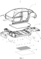
- FIG. 1 is a schematic structural diagram of a vehicle according to an embodiment of this application.
- an embodiment of this application provides a vehicle 1, where the vehicle 1 includes a lower vehicle body 6 and an upper vehicle body 7, and the upper vehicle body 7 is connected to the lower vehicle body 6.
- This embodiment of this application does not limit the method of connection between the upper vehicle body 7 and the lower vehicle body 6.
- the two may be connected by welding or a detachable connection.
- the upper vehicle body 7 and the lower vehicle body 6 are detachably connected.
- the upper vehicle body 7 and the lower vehicle body 6 are detachably connected through a connector.
- the embodiments of this application do not limit the types of the connector.
- the connector may include at least one of a bolt, a nut, a stud, a screw, and a pin.
- the connector may further include a snap.
- the upper vehicle body 7 and the lower vehicle body 6 are detachably connected, which enables the separation and decoupling of the upper vehicle body 7 and the lower vehicle body 6, thereby implementing independent development of the upper vehicle body 7 and the lower vehicle body 6. This allows for the replacement of the upper vehicle body 7 and the lower vehicle body 6 according to requirements, reducing the development cycle and lowering costs.
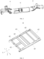
- FIG. 2 is a schematic exploded view of a structure of a lower vehicle body according to an embodiment of this application.
- the lower vehicle body 6 of a vehicle 1 of this embodiment of this application includes a front compartment 61, a energy compartment frame 62, and a rear compartment 63, where the energy compartment frame 62 is configured for mounting battery cells 5, and the front compartment 61 and the rear compartment 63 are connected to two ends of the energy compartment frame 62, where at least one of the front compartment 61 and the rear compartment 63 is detachably connected to the energy compartment frame 62.
- This embodiment of this application does not limit the specific methods of detachable connection between the front compartment 61 and the energy compartment frame 62, as well as between the rear compartment 63 and the energy compartment frame 62.
- the detachable connection may be realized by snapping, threaded connection, riveting, and the like.
- At least one of the front compartment 61 and the rear compartment 63 is detachably connected to the energy compartment frame 62.
- the two or three parts into which the lower vehicle body 6 is divided can be transported and stored separately. Therefore, the flexibility in storage and transportation is increased, and storage and transportation are more convenient, thereby reducing the costs of storage and transportation.
- the front compartment 61, the energy compartment frame 62, and the rear compartment 63 are detachably connected, enabling separation and connection of the front compartment 61, the energy compartment frame 62, and the rear compartment 63.
- the independent development of the three can be implemented, which allows the front compartment 61, the energy compartment frame 62, and the rear compartment 63 to be replaced as needed, shortening the development cycle and reducing the costs.
- both the front compartment 61 and the rear compartment 63 are detachably connected to the energy compartment frame 62.
- the front compartment 61 and the rear compartment 63 are configured as both detachably connected to the energy compartment frame 62.
- the lower vehicle body 6 is divided into three detachable parts. During transportation and storage, these three parts can be transported and stored separately, which is extremely convenient, further reducing the costs of storage and transportation.
- At least one of the front compartment 61 and the rear compartment 63 is detachably connected to the energy compartment frame 62 through fasteners 64.
- the fastener 64 may be a bolt and nut assembly, or a connector such as a rivet.
- the front compartment 61 and the rear compartment 63 are connected through fasteners 64.
- this connection method offers higher structural strength, thereby improving the stability, reliability, and durability of the lower vehicle body 6.
- the fastener 64 includes a bolt.
- connectors there are a plurality of connectors, and at least part of the connectors are bolts.
- Bolts are highly standardized and easy to replace. Bolt connections are easy to disassemble and assemble, which is conducive to improving assembly efficiency.
- connections using bolts allow for the decoupling of physical structures of the front compartment 61, the energy compartment frame 62, and the rear compartment 63.
- FIG. 3 is a schematic structural diagram of a energy compartment frame of a lower vehicle body according to an embodiment of this application; and FIG. 4 is a schematic exploded view of a structure of a energy compartment frame, a battery cell, and a guard plate of a lower vehicle body according to an embodiment of this application.
- the energy compartment frame 62 includes a floor 621, two first transverse beams 622 oppositely arranged in the first direction X, and two first longitudinal beams 623 oppositely arranged in the second direction Y, where the first longitudinal beams 623 connect the two first transverse beams 622; the floor 621, the two first transverse beams 622, and the two first longitudinal beams 623 enclose an accommodating cavity 624 for accommodating battery cells 5; and the first direction X intersects with the second direction Y
- the floor 621 in the embodiments of this application may be used as the floor 621 of the vehicle 1.
- the floor 621 is configured for connecting to the battery cells 5.
- the battery cell 5 is bonded to the floor 621.
- the two first transverse beams 622 and the two first longitudinal beams 623 in the embodiments of this application may be alternately arranged and connected end to end, and the first longitudinal beam 623 may also exceed the first transverse beam 622 along its length direction, and the first transverse beam 622 may also exceed the first longitudinal beam 623 along its length direction.
- the embodiments of this application do not limit whether the structures of the two first transverse beams 622 are the same, and the structures of the two first transverse beams 622 may be the same or different. The same is true for the first longitudinal beam 623, which will not be repeated here in this application.
- the first direction X is perpendicular to the second direction Y
- the energy compartment frame 62 is configured as including two first transverse beams 622 and two first longitudinal beams 623, which together with the floor 621, define an accommodating space for accommodating battery cells 5. This configuration facilitates manufacturing and can create a large accommodating space.
- the two first transverse beams 622 and two first longitudinal beams 623 are connected by welding.
- a sealing member is provided between, at least one of the two first transverse beams 622 and the two first longitudinal beams 623, and the floor 621.
- the sealing member is at least one of a sealing foam or a sealing adhesive.
- the two first transverse beams 622 and two first longitudinal beams 623 are both connected to the floor 621 through connectors.
- the connector is a bolt or a rivet.
- the front compartment 61 and the rear compartment 63 are detachably connected to two ends of the first longitudinal beam 623 respectively.
- the front compartment 61 is detachably connected to two ends at a same side of the two first longitudinal beams 623
- the rear compartment 63 is detachably connected to another two ends at a same side of the two first longitudinal beams 623.
- the front compartment 61, the energy compartment frame, and the rear compartment 63 are arranged in the first direction X in sequence.
- the front compartment 61 and the rear compartment 63 are respectively connected to the two ends of the first longitudinal beam 623.
- the front compartment 61, the energy compartment frame, and the rear compartment 63 are generally arranged in sequence in a longitudinal direction. Therefore, when compared with connecting to the first transverse beam 622, connecting to the first longitudinal beam 623 extending along the longitudinal direction is more convenient.
- the first longitudinal beam 623 generally has greater rigidity and strength, therefore, the reliability of connection to the first longitudinal beam 623 is higher.
- the lower vehicle body 6 further includes a second transverse beam 625, where the second transverse beam 625 is located between the two first transverse beams 622, and two ends of the second transverse beam 625 are respectively connected to the two first longitudinal beams 623; where the second transverse beam 625 is configured for connecting to battery cells 5.
- the second transverse beam 625 in the embodiments of this application is located in the accommodating cavity 624.
- the second transverse beam 625 is parallel to the first transverse beam 622.
- the second transverse beam 625 is provided in plurality, and the plurality of second transverse beams 625 are arranged at intervals along the first direction X, with at least part of the plurality of battery cells 5 being clamped between two adjacent second transverse beams 625.
- the embodiments of this application do not limit the method of connection between the battery cell 5 and the second transverse beam 625.
- the battery cell 5 is bonded to the second transverse beam 625.
- the embodiments of this application do not limit the method of connection between the second transverse beam 625 and the first longitudinal beam 623.
- the two may be connected by threaded connection or welding.
- the second transverse beam 625 is connected to the battery cell 5, thereby limiting the position of the battery cell 5 at the connection point. This reduces the extent of size changes caused by swelling of the battery cell 5 during the charging and discharging process, thereby prolonging the service life of the battery cell 5.
- the second transverse beam 625 is connected to a lateral side of the battery cell 5.
- the second transverse beam 625 being connected to a lateral side of the battery cell 5 makes the effect of size restriction more evident.
- FIG. 5 is a schematic structural diagram of a front compartment of a lower vehicle body according to an embodiment of this application.
- the front compartment 61 includes a front anti-collision beam 611, a third transverse beam 612, and two second longitudinal beams 613, where the third transverse beam 612 and the front anti-collision beam 611 are oppositely arranged in a first direction X, the two second longitudinal beams 613 are oppositely arranged in a second direction Y, the second longitudinal beams 613 are connected to the third transverse beam 612 and the front anti-collision beam 611, and the second direction Y intersects with the first direction X.
- the embodiments of this application do not limit the method of connection between the second longitudinal beam 613 and the third transverse beam 612, and between the second longitudinal beam 613 and the front anti-collision beam 611.
- the second longitudinal beam 613 may be connected to the third transverse beam 612 through integral molding, welding, threaded connection, rivet connection, bonding, or FDS.
- FDS integral molding, welding, threaded connection, rivet connection, bonding, or FDS.
- the first direction X is perpendicular to the second direction Y
- the front anti-collision beam 611, the third transverse beam 612, and two second longitudinal beams 613 are arranged, forming an approximately quadrilateral structure either on their own or in combination with another component. This structure has good support stability and facilitates the arrangement of other structures.
- the front compartment 61 further includes two first torsion boxes 614, where the two first torsion boxes 614 are oppositely arranged in the second direction Y and are connected to the two second longitudinal beams 613 in one-to-one correspondence, the first torsion boxes 614 are arranged on one side of the second longitudinal beams 613 adjacent to the energy compartment frame 62, the third transverse beam 612 is connected to the two first torsion boxes 614, and the first torsion boxes 614 are detachably connected to the energy compartment frame 62.
- first torsion box 614 is connected to both the second longitudinal beam 613 and the third transverse beam 612 by a method of combination of threaded connection and bonding.
- a method of combination of riveting and bonding may be used, or riveting can be used alone.
- the first torsion box 614 is arranged, and the second longitudinal beam 613 is detachably connected to the energy compartment frame 62 through the first torsion box 614, which significantly increases the structural strength of the connection between the second longitudinal beam 613 and the energy compartment frame 62, thereby enhancing the structural reliability of the lower vehicle body 6.
- the energy compartment frame 62 includes a floor 621, two first transverse beams 622 oppositely arranged in the first direction X, and two first longitudinal beams 623 oppositely arranged in the second direction Y, where the first longitudinal beams 623 connect the two first transverse beams 622; the floor 621, the two first transverse beams 622, and the two first longitudinal beams 623 enclose an accommodating cavity 624 for accommodating battery cells 5; and the two first torsion boxes 614 are detachably connected to the two first longitudinal beams 623 in one-to-one correspondence.
- the embodiments of this application do not limit the method of connection between the first torsion box 614 and the first longitudinal beam 623.
- the first torsion box 614 and the first longitudinal beam 623 may be connected through threaded connection or riveting.
- the first torsion box 614 is detachably connected to the first longitudinal beam 623, and the first longitudinal beam 623 extends along the longitudinal direction. Therefore, when compared with connecting to the first transverse beam 622, connecting to the first longitudinal beam 623 extending along the longitudinal direction is more convenient.
- the first torsion box 614 includes a box main body 615 and a connecting part 616, where the box main body 615 is connected to the second longitudinal beam 613, and the connecting part 616 includes a first wall body 617 and a second wall body 618 connected by bending, where the first wall body 617 is opposite and detachably connected to the first longitudinal beam 623 in the second direction Y, the second wall body 618 is opposite and detachably connected to the first longitudinal beam 623 in a third direction Z, and the first direction X, the second direction Y, and the third direction Z are perpendicular to each other.
- the first wall body 617 and the first longitudinal beam 623 in the embodiments of this application may be directly attached and then connected through fasteners 64 such as bolts.
- the first wall body 617 and the first longitudinal beam 623 may be connected after another cushion member is sandwiched therebetween.
- the same is true for the second wall body 618 and the first longitudinal beam 623, which will not be repeated here in this application.
- the first wall body 617 in the embodiments of this application is perpendicular to the second direction Y, and the second wall body 618 is perpendicular to the third direction Z.
- the first torsion box 614 is configured as including a first wall body 617 and a second wall body 618 that are bent relative to each other.
- the first wall body 617 and the second wall body 618 are both connected to the first longitudinal beam 623, meaning that the first torsion box 614 is connected to the first longitudinal beam 623 in two directions. This greatly increases the structural strength of the connection between the first torsion box 614 and the first longitudinal beam 623, thereby improving the reliability of the connection.
- the front compartment 61 further includes two shock towers 619, and the two shock towers 619 are connected to the two second longitudinal beams 613 in one-to-one correspondence.
- a shock tower 619 is provided on the second longitudinal beam 613, providing lateral support for offset collisions and also support for a shock absorber.
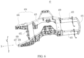
- FIG. 6 is a schematic structural diagram of a rear compartment of a lower vehicle body according to an embodiment of this application.
- the rear compartment 63 includes a rear anti-collision beam 631, a fourth transverse beam 632, and two third longitudinal beams 633, where the fourth transverse beam 632 and the rear anti-collision beam 631 are oppositely arranged in a first direction X, the two third longitudinal beams 633 are oppositely arranged in a second direction Y, the third longitudinal beams 633 are connected to the fourth transverse beam 632 and the rear anti-collision beam 631, and the second direction Y intersects with the first direction X.
- the embodiments of this application do not limit the method of connection between the third longitudinal beam 633 and the fourth transverse beam 632, and between the third longitudinal beam 633 and the rear anti-collision beam 631.
- the third longitudinal beam 633 may be connected to the fourth transverse beam 632 through integral molding, welding, threaded connection, rivet connection, or FDS.
- a structural adhesive may be used for further connection. The same is true for the third longitudinal beam 633 and the front anti-collision beam 611, which will not be repeated here in this application.
- the first direction X is perpendicular to the second direction Y
- the rear anti-collision beam 631, the fourth transverse beam 632, and two third longitudinal beams 633 are arranged, forming an approximately quadrilateral structure either on their own or in combination with another component. This structure has good support stability and facilitates the arrangement of other structures.
- the rear compartment 63 further includes two second torsion boxes 634, where the two second torsion boxes 634 are oppositely arranged in the second direction Y and are connected to the two third longitudinal beams 633 in one-to-one correspondence, the second torsion boxes 634 are arranged on one side of the third longitudinal beams 633 adjacent to the energy compartment frame 62, the fourth transverse beam 632 is connected to the two second torsion boxes 634, and the second torsion boxes 634 are detachably connected to the energy compartment frame 62.
- the embodiments of this application do not limit the method of connection between the second torsion box 634 and the third longitudinal beam 633.
- the second torsion box 634 is connected to the third longitudinal beam 633 or the fourth transverse beam 632 by a method of combination of threaded connection and bonding.
- a method of combination of riveting and bonding may be used, or riveting can be used alone.
- the second torsion box 634 is arranged, and the third longitudinal beam 633 is detachably connected to the energy compartment frame 62 through the second torsion box 634, which significantly increases the structural strength of the connection between the third longitudinal beam 633 and the energy compartment frame 62, thereby enhancing the structural reliability of the lower vehicle body 6.
- the energy compartment frame 62 includes a floor 621, two first transverse beams 622 oppositely arranged in the first direction X, and two first longitudinal beams 623 oppositely arranged in the second direction Y, where the first longitudinal beams 623 connect the two first transverse beams 622; the floor 621, the two first transverse beams 622, and the two first longitudinal beams 623 enclose an accommodating cavity 624 for accommodating battery cells 5; and the two second torsion boxes 634 are detachably connected to the two first longitudinal beams 623 in one-to-one correspondence.
- the embodiments of this application do not limit the method of connection between the second torsion box 634 and the first longitudinal beam 623.
- the second torsion box 634 and the first longitudinal beam 623 may be connected through threaded connection or riveting.
- the second torsion box 634 is detachably connected to the first longitudinal beam 623, and the first longitudinal beam 623 extends along the longitudinal direction. Therefore, when compared with the solution of connecting to the first transverse beam 622, connecting to the first longitudinal beam 623 extending along the longitudinal direction is more convenient.
- the second torsion box 634 includes a box body 635 and a functional part 636, where the box body 635 is connected to the third longitudinal beam 633, and the functional part 636 includes a third wall body 637 and a fourth wall body 638 that are bent and connected, where the third wall body 637 is opposite and detachably connected to the first longitudinal beam 623 in the second direction Y, the fourth wall body 638 is opposite and detachably connected to the first longitudinal beam 623 in a third direction Z, and the first direction X, the second direction Y, and the third direction Z are perpendicular to each other.
- the third wall body 637 and the first longitudinal beam 623 in the embodiments of this application may be directly attached and then connected through fasteners 64 such as bolts; alternatively, the third wall body 637 and the first longitudinal beam 623 may be connected after another cushion member is sandwiched therebetween.
- fasteners 64 such as bolts
- the third wall body 637 and the first longitudinal beam 623 may be connected after another cushion member is sandwiched therebetween.
- the fourth wall body 638 and the first longitudinal beam 623 which will not be repeated here in this application.
- the third wall body 637 in the embodiments of this application is perpendicular to the second direction Y, and the fourth wall body 638 is perpendicular to the third direction Z.
- the second torsion box 634 is configured as including a third wall body 637 and a fourth wall body 638 that are bent relative to each other.
- the third wall body 637 and the fourth wall body 638 are both connected to the first longitudinal beam 623, meaning that the first torsion box 614 is connected to the first longitudinal beam 623 in two directions. This greatly increases the structural strength of the connection between the second torsion box 634 and the first longitudinal beam 623, thereby improving the reliability of the connection.
- the rear compartment 63 further includes a fifth transverse beam 639, and the fifth transverse beam 639 is connected to the two box bodies 635 and arranged at an end of the box bodies 635 adjacent to the third longitudinal beam 633.
- the fifth transverse beam 639 may be connected to the box body 635 by a method of threaded connection, riveting, or a combination of threaded connection and bonding.
- the fifth transverse beam 639 is arranged to further improve the structural stability and service durability of the rear compartment 63.
- the embodiments of this application further provide a skateboard chassis 8, including the lower vehicle body 6 and battery cells 5, where the battery cells 5 are connected to the energy compartment frame 62.
- the battery cells 5 are connected to the floor 621 of the energy compartment frame 62.
- the skateboard chassis 8 further includes a guard plate 81, where the guard plate 81 is connected to the first transverse beam 622 and the first longitudinal beam 623 and covers an opening of the accommodating cavity 624.
- the guard plate 81 is connected to the first transverse beam 622 and the first longitudinal beam 623 by a method of combination of threaded connection and using a sealing member.
- the sealing member is foam.
- the embodiments of this application provide a lower vehicle body 6, where the lower vehicle body 6 of a vehicle 6 of the embodiments of this application includes a front compartment 61, a energy compartment frame 62, and a rear compartment 63, where the energy compartment frame 62 is configured for mounting battery cells 5, and the front compartment 61 and the rear compartment 63 are connected to two ends of the energy compartment frame 62, where both the front compartment 61 and the rear compartment 63 are detachably connected to the energy compartment frame 62.
Landscapes
- Engineering & Computer Science (AREA)
- Chemical & Material Sciences (AREA)
- Combustion & Propulsion (AREA)
- Transportation (AREA)
- Mechanical Engineering (AREA)
- Body Structure For Vehicles (AREA)
- Arrangement Or Mounting Of Propulsion Units For Vehicles (AREA)
- Battery Mounting, Suspending (AREA)
Abstract
Description
- This application relates to the field of vehicle technologies, and in particular, to a lower vehicle body, a skateboard chassis, and a vehicle.
- At present, with the rapid development of automation and intelligence, new energy vehicles are beloved and purchased by more people.
- How costs are reduced is a research direction in vehicle technology.
- This application provides a lower vehicle body, a skateboard chassis, and a vehicle, which can reduce the costs of vehicles.
- According to a first aspect, this application provides a lower vehicle body of a vehicle, including a front compartment, a energy compartment frame, and a rear compartment, where the energy compartment frame is configured for mounting battery cells, and the front compartment and the rear compartment are connected to two ends of the energy compartment frame, where at least one of the front compartment and the rear compartment is detachably connected to the energy compartment frame.
- In the foregoing technical solution, at least one of the front compartment and the rear compartment is detachably connected to the energy compartment frame. As a result, compared with a structure integrating the front compartment, the rear compartment, and the energy compartment frame, the two or three parts into which the lower vehicle body is divided can be transported and stored separately. Therefore, the flexibility in storage and transportation is increased, and storage and transportation are more convenient, thereby reducing the costs of storage and transportation.
- In some embodiments, both the front compartment and the rear compartment are detachably connected to the energy compartment frame.
- In the foregoing technical solution, the front compartment and the rear compartment are configured as both detachably connected to the energy compartment frame. As a result, the lower vehicle body is divided into three detachable parts. During transportation and storage, these three parts can be transported and stored separately, which is extremely convenient, further reducing the costs of storage and transportation.
- In some embodiments, at least one of the front compartment and the rear compartment is detachably connected to the energy compartment frame through fasteners.
- In the foregoing technical solution, the front compartment and the rear compartment are connected through fasteners. When compared with detachable connections such as snap-fit, this connection method offers higher structural strength, thereby improving the stability, reliability, and durability of the lower vehicle body.
- In some embodiments, the energy compartment frame includes a floor, two first transverse beams oppositely arranged in the first direction, and two first longitudinal beams oppositely arranged in the second direction, where the first longitudinal beams connect the two first transverse beams; the floor, the two first transverse beams, and the two first longitudinal beams enclose an accommodating cavity for accommodating battery cells; and the first direction intersects with the second direction.
- In the foregoing technical solution, the energy compartment frame is configured as including two first transverse beams and two first longitudinal beams, which together with the floor, define an accommodating space for accommodating battery cells. This configuration facilitates manufacturing and can create a large accommodating space.
- In some embodiments, the front compartment and the rear compartment are detachably connected to two ends of the first longitudinal beam respectively.
- In the foregoing technical solution, the front compartment and the rear compartment are configured as connected to the two ends of the first longitudinal beam respectively. The front compartment, the energy compartment frame, and the rear compartment are generally arranged in sequence in a longitudinal direction. Therefore, when compared with connecting to the first transverse beam, connecting to the first longitudinal beam extending along the longitudinal direction is more convenient. In addition, the first longitudinal beam generally has greater rigidity and strength, therefore, the reliability of connection to the first longitudinal beam is higher.
- In some embodiments, the lower vehicle body further includes a second transverse beam, where the second transverse beam is located between the two first transverse beams, and two ends of the second transverse beam are respectively connected to the two first longitudinal beams; where the second transverse beam is configured for connecting to battery cells.
- In the foregoing technical solution, the second transverse beam is connected to the battery cell, thereby limiting the position of the battery cell at the connection point. This reduces the extent of size changes caused by swelling of the battery cell during the charging and discharging process, thereby prolonging the service life of the battery cell.
- In some embodiments, the front compartment includes a front anti-collision beam, a third transverse beam, and two second longitudinal beams, where the third transverse beam and the front anti-collision beam are oppositely arranged in a first direction, the two second longitudinal beams are oppositely arranged in a second direction, the second longitudinal beams are connected to the third transverse beam and the front anti-collision beam, and the second direction intersects with the first direction.
- In the foregoing technical solution, the front anti-collision beam, the third transverse beam, and two second longitudinal beams are arranged, forming an approximately quadrilateral structure either on their own or in combination with another component. This structure has good support stability and facilitates the arrangement of other structures.
- In some embodiments, the front compartment further includes two first torsion boxes, where the two first torsion boxes are oppositely arranged in the second direction and are connected to the two second longitudinal beams in one-to-one correspondence, the first torsion boxes are arranged on one side of the second longitudinal beams adjacent to the energy compartment frame, the third transverse beam is connected to the two first torsion boxes, and the first torsion boxes are detachably connected to the energy compartment frame.
- In the foregoing technical solution, the first torsion box is arranged, and the second longitudinal beam is detachably connected to the energy compartment frame through the first torsion box, which significantly increases the structural strength of the connection between the second longitudinal beam and the energy compartment frame, thereby enhancing the structural reliability of the lower vehicle body.
- In some embodiments, the energy compartment frame includes a floor, two first transverse beams oppositely arranged in the first direction, and two first longitudinal beams oppositely arranged in the second direction, where the first longitudinal beams connect the two first transverse beams; the floor, the two first transverse beams, and the two first longitudinal beams enclose an accommodating cavity for accommodating battery cells; and the two first torsion boxes are detachably connected to the two first longitudinal beams in one-to-one correspondence.
- In the foregoing technical solution, the first torsion box is detachably connected to the first longitudinal beam, and the first longitudinal beam extends along the longitudinal direction. Therefore, when compared with connecting to the first transverse beam, connecting to the first longitudinal beam extending along the longitudinal direction is more convenient.
- In some embodiments, the first torsion box includes a box main body and a connecting part, where the box main body is connected to the second longitudinal beam, and the connecting part includes a first wall body and a second wall body connected by bending, where the first wall body is opposite and detachably connected to the first longitudinal beam in the second direction, the second wall body is opposite and detachably connected to the first longitudinal beam in a third direction, and the first direction, the second direction, and the third direction are perpendicular to each other.
- In the foregoing technical solution, the first torsion box is configured as including a first wall body and a second wall body that are bent relative to each other. The first wall body and the second wall body are both connected to the first longitudinal beam, meaning that the first torsion box is connected to the first longitudinal beam in two directions. This greatly increases the structural strength of the connection between the first torsion box and the first longitudinal beam, thereby improving the reliability of the connection.
- In some embodiments, the front compartment further includes two shock towers, and the two shock towers are connected to the two second longitudinal beams in one-to-one correspondence.
- In the foregoing technical solution, a shock tower is provided on the second longitudinal beam, providing lateral support for offset collisions and also support for a shock absorber.
- In some embodiments, the rear compartment includes a rear anti-collision beam, a fourth transverse beam, and two third longitudinal beams, where the fourth transverse beam and the rear anti-collision beam are oppositely arranged in a first direction, the two third longitudinal beams are oppositely arranged in a second direction, the third longitudinal beams are connected to the fourth transverse beam and the rear anti-collision beam, and the second direction intersects with the first direction.
- In the foregoing technical solution, a rear anti-collision beam, a fourth transverse beam, and two third longitudinal beams are arranged, forming an approximately quadrilateral structure either on their own or in combination with another component. This structure has good support stability and facilitates the arrangement of other structures.
- In some embodiments, the rear compartment further includes two second torsion boxes, where the two second torsion boxes are oppositely arranged in the second direction and are connected to the two third longitudinal beams in one-to-one correspondence, the second torsion boxes are arranged on one side of the third longitudinal beams adjacent to the energy compartment frame, the fourth transverse beam is connected to the two second torsion boxes, and the second torsion boxes are detachably connected to the energy compartment frame.
- In the foregoing technical solution, the second torsion box is arranged, and the third longitudinal beam is detachably connected to the energy compartment frame through the second torsion box, which significantly increases the structural strength of the connection between the third longitudinal beam and the energy compartment frame, thereby enhancing the structural reliability of the lower vehicle body.
- In some embodiments, the energy compartment frame includes a floor, two first transverse beams oppositely arranged in the first direction, and two first longitudinal beams oppositely arranged in the second direction, where the first longitudinal beams connect the two first transverse beams; the floor, the two first transverse beams, and the two first longitudinal beams enclose an accommodating cavity for accommodating battery cells; and the two second torsion boxes are detachably connected to the two first longitudinal beams in one-to-one correspondence.
- In the foregoing technical solution, the second torsion box is detachably connected to the first longitudinal beam, and the first longitudinal beam extends along the longitudinal direction. Therefore, when compared with the solution of connecting to the first transverse beam, connecting to the first longitudinal beam extending along the longitudinal direction is more convenient.
- In some embodiments, the second torsion box includes a box body and a functional part, where the box body is connected to the third longitudinal beam, and the functional part includes a third wall body and a fourth wall body connected by bending, where the third wall body is opposite and detachably connected to the first longitudinal beam in the second direction, the fourth wall body is opposite and detachably connected to the first longitudinal beam in a third direction, and the first direction, the second direction, and the third direction are perpendicular to each other.
- In the foregoing technical solution, the second torsion box is configured as including a third wall body and a fourth wall body that are bent relative to each other. The third wall body and the fourth wall body are both connected to the first longitudinal beam, meaning that the first torsion box is connected to the first longitudinal beam in two directions. This greatly increases the structural strength of the connection between the second torsion box and the first
longitudinal beam 623, thereby improving the reliability of the connection. - In some embodiments, the rear compartment further includes a fifth transverse beam, and the fifth transverse beam is connected to the two box bodies and arranged at an end of the box bodies adjacent to the third longitudinal beam.
- In the foregoing technical solution, the fifth transverse beam is arranged to further improve the structural stability and service durability of the rear compartment.
- According to a second aspect, the embodiments of this application further provide a skateboard chassis, including the lower vehicle body according to any one of the foregoing embodiments and battery cells, where the battery cell is connected to the energy compartment frame.
- According to a third aspect, the embodiments of this application further provide a vehicle, including the lower vehicle body and upper vehicle body according to any one of the foregoing embodiments, where the upper vehicle body is connected to the lower vehicle body.
- In some embodiments, the upper vehicle body and the lower vehicle body are detachably connected.
- The upper vehicle body and the lower vehicle body are detachably connected, which enables the separation and decoupling of the upper vehicle body and the lower vehicle body, thereby implementing independent development of the upper vehicle body and the lower vehicle body. This allows for the replacement of the upper vehicle body and the lower vehicle body according to requirements, reducing the development cycle and lowering costs.
- The following describes features, advantages, and technical effects of the example embodiments of this application with reference to the accompanying drawings.
-
FIG. 1 is a schematic structural diagram of a vehicle according to an embodiment of this application; -
FIG. 2 is a schematic exploded view of a structure of a lower vehicle body according to an embodiment of this application; -
FIG. 3 is a schematic structural diagram of a energy compartment frame of a lower vehicle body according to an embodiment of this application; -
FIG. 4 is a schematic exploded view of a structure of a energy compartment frame, a battery cell, and a guard plate of a lower vehicle body according to an embodiment of this application; -
FIG. 5 is a schematic structural diagram of a front compartment of a lower vehicle body according to an embodiment of this application; and -
FIG. 6 is a schematic structural diagram of a rear compartment of a lower vehicle body according to an embodiment of this application. - The accompanying drawings are not drawn to scale.
- Reference signs in the specific embodiments are described as follows:
- 1. vehicle; 5. battery cell; 6. lower vehicle body;
- 61. front compartment; 611. front anti-collision beam; 612. third transverse beam; 613. second longitudinal beam; 614. first torsion box; 615. box main body; 616. connecting part; 617. first wall body; 618. second wall body; 619. shock tower;
- 62. energy compartment frame; 621. floor; 622. first transverse beam; 623. first longitudinal beam; 624. accommodating cavity; 625. second transverse beam;
- 63. rear compartment; 631. rear anti-collision beam; 632. fourth transverse beam; 633. third longitudinal beam; 634. second torsion box; 635. box body; 636. functional part; 637. third wall body; 638. fourth wall body; 639. fifth transverse beam;
- 64. fastener;
- 7. upper vehicle body;
- 8. skateboard chassis; 81. guard plate;
- X. first direction; Y second direction; and Z. third direction.
- To make the objectives, technical solutions, and advantages of the embodiments of this application clearer, the following clearly and completely describes the technical solutions in the embodiments of this application with reference to the accompanying drawings in the embodiments of this application. Apparently, the described embodiments are some but not all of the embodiments of this application. All other embodiments obtained by persons of ordinary skill in the art based on the embodiments of this application without creative efforts shall fall within the protection scope of this application.
- Unless otherwise defined, all technical and scientific terms used in this application shall have the same meanings as commonly understood by persons skilled in the art to which this application relates. The terms used in the specification of this application are intended to merely describe the specific embodiments rather than to limit this application. The terms "include", "comprise", and any variations thereof in the specification and claims of this application as well as the foregoing description of drawings are intended to cover non-exclusive inclusions. In the specification, claims, or accompanying drawings of this application, the terms "first", "second", and the like are intended to distinguish between different objects rather than to indicate a particular order or relative importance.
- Reference to "embodiment" in this application means that specific features, structures, or characteristics described with reference to the embodiment may be included in at least one embodiment of this application. The word "embodiment" appearing in various positions in the specification does not necessarily refer to the same embodiment or an independent or alternative embodiment that is exclusive of other embodiments.
- In the description of this application, it should be noted that unless otherwise specified and defined explicitly, the terms "mount", "connect", "join", and "attach" should be understood in their general senses. For example, they may refer to a fixed connection, a detachable connection, or an integral connection; and may refer to a direct connection, an indirect connection via an intermediate medium, or an internal communication between two elements. Persons of ordinary skills in the art can understand specific meanings of these terms in this application as appropriate to specific situations.
- The term "and/or" in this application is only an associative relationship for describing associated objects, indicating that three relationships may be present. For example, A and/or B may indicate three cases: presence of only A; presence of both A and B; and presence of only B. In addition, the character "/" in this application generally indicates an "or" relationship between contextually associated objects.
- In the embodiments of this application, the same reference signs denote the same components. For brevity, in different embodiments, detailed descriptions of the same components are not repeated. It should be understood that, as shown in the accompanying drawings, sizes such as thickness, length, and width of various components and sizes such as thickness, length, and width of integrated devices in the embodiments of this application are merely for illustrative purposes and should not constitute any limitations on this application.
- In this application, "a plurality of" means more than two (inclusive).
- In the related art, a lower vehicle body of a vehicle usually includes three parts: front compartment, energy compartment frame, and rear compartment, and the three parts are integrated. An integrated lower vehicle body can improve the rigidity of the vehicle, thereby improving the impact resistance of the vehicle.
- However, a lower vehicle body with an integrated structure occupies a large space, so the transportation and storage costs are high.
- In view of this, this application provides a technical solution, which separates at least two among the front compartment, the energy compartment frame, and the rear compartment, which originally form an integrated structure, by allowing at least one of the front compartment and the rear compartment to be detachably connected to the energy compartment frame. This facilitates transportation and storage and reduces the transportation and storage costs.
-
FIG. 1 is a schematic structural diagram of a vehicle according to an embodiment of this application. - As shown in
FIG. 1 , an embodiment of this application provides avehicle 1, where thevehicle 1 includes a lower vehicle body 6 and anupper vehicle body 7, and theupper vehicle body 7 is connected to the lower vehicle body 6. - This embodiment of this application does not limit the method of connection between the
upper vehicle body 7 and the lower vehicle body 6. For example, the two may be connected by welding or a detachable connection. - In some embodiments, the
upper vehicle body 7 and the lower vehicle body 6 are detachably connected. - For example, the
upper vehicle body 7 and the lower vehicle body 6 are detachably connected through a connector. The embodiments of this application do not limit the types of the connector. In some examples, the connector may include at least one of a bolt, a nut, a stud, a screw, and a pin. In other examples, the connector may further include a snap. - In the embodiments of this application, the
upper vehicle body 7 and the lower vehicle body 6 are detachably connected, which enables the separation and decoupling of theupper vehicle body 7 and the lower vehicle body 6, thereby implementing independent development of theupper vehicle body 7 and the lower vehicle body 6. This allows for the replacement of theupper vehicle body 7 and the lower vehicle body 6 according to requirements, reducing the development cycle and lowering costs. -
FIG. 2 is a schematic exploded view of a structure of a lower vehicle body according to an embodiment of this application. - As shown in
FIG. 2 , the lower vehicle body 6 of avehicle 1 of this embodiment of this application includes afront compartment 61, aenergy compartment frame 62, and arear compartment 63, where theenergy compartment frame 62 is configured for mountingbattery cells 5, and thefront compartment 61 and therear compartment 63 are connected to two ends of theenergy compartment frame 62, where at least one of thefront compartment 61 and therear compartment 63 is detachably connected to theenergy compartment frame 62. - This embodiment of this application does not limit the specific methods of detachable connection between the
front compartment 61 and theenergy compartment frame 62, as well as between therear compartment 63 and theenergy compartment frame 62. For example, the detachable connection may be realized by snapping, threaded connection, riveting, and the like. - At least one of the
front compartment 61 and therear compartment 63 is detachably connected to theenergy compartment frame 62. As a result, compared with a structure integrating thefront compartment 61, therear compartment 63, and theenergy compartment frame 62, the two or three parts into which the lower vehicle body 6 is divided can be transported and stored separately. Therefore, the flexibility in storage and transportation is increased, and storage and transportation are more convenient, thereby reducing the costs of storage and transportation. In addition, thefront compartment 61, theenergy compartment frame 62, and therear compartment 63 are detachably connected, enabling separation and connection of thefront compartment 61, theenergy compartment frame 62, and therear compartment 63. Thus, the independent development of the three can be implemented, which allows thefront compartment 61, theenergy compartment frame 62, and therear compartment 63 to be replaced as needed, shortening the development cycle and reducing the costs. - In some embodiments, both the
front compartment 61 and therear compartment 63 are detachably connected to theenergy compartment frame 62. - The
front compartment 61 and therear compartment 63 are configured as both detachably connected to theenergy compartment frame 62. As a result, the lower vehicle body 6 is divided into three detachable parts. During transportation and storage, these three parts can be transported and stored separately, which is extremely convenient, further reducing the costs of storage and transportation. - In some embodiments, at least one of the
front compartment 61 and therear compartment 63 is detachably connected to theenergy compartment frame 62 throughfasteners 64. - The embodiments of this application do not limit the specific types of the
fasteners 64. For example, thefastener 64 may be a bolt and nut assembly, or a connector such as a rivet. - The
front compartment 61 and therear compartment 63 are connected throughfasteners 64. When compared with detachable connections such as snap-fit, this connection method offers higher structural strength, thereby improving the stability, reliability, and durability of the lower vehicle body 6. - In some embodiments, the
fastener 64 includes a bolt. - For example, there are a plurality of connectors, and at least part of the connectors are bolts.
- Bolts are highly standardized and easy to replace. Bolt connections are easy to disassemble and assemble, which is conducive to improving assembly efficiency.
- Compared with connection methods such as flow drill screwing (FDS) and self-pierce riveting (SPR), connections using bolts allow for the decoupling of physical structures of the
front compartment 61, theenergy compartment frame 62, and therear compartment 63. -
FIG. 3 is a schematic structural diagram of a energy compartment frame of a lower vehicle body according to an embodiment of this application; andFIG. 4 is a schematic exploded view of a structure of a energy compartment frame, a battery cell, and a guard plate of a lower vehicle body according to an embodiment of this application. - As shown in
FIGs. 3 and4 , in some embodiments, theenergy compartment frame 62 includes afloor 621, two firsttransverse beams 622 oppositely arranged in the first direction X, and two firstlongitudinal beams 623 oppositely arranged in the second direction Y, where the firstlongitudinal beams 623 connect the two firsttransverse beams 622; thefloor 621, the two firsttransverse beams 622, and the two firstlongitudinal beams 623 enclose anaccommodating cavity 624 for accommodatingbattery cells 5; and the first direction X intersects with the second direction Y - The
floor 621 in the embodiments of this application may be used as thefloor 621 of thevehicle 1. Optionally, thefloor 621 is configured for connecting to thebattery cells 5. Further optionally, thebattery cell 5 is bonded to thefloor 621. - For example, the two first
transverse beams 622 and the two firstlongitudinal beams 623 in the embodiments of this application may be alternately arranged and connected end to end, and the firstlongitudinal beam 623 may also exceed the firsttransverse beam 622 along its length direction, and the firsttransverse beam 622 may also exceed the firstlongitudinal beam 623 along its length direction. - The embodiments of this application do not limit whether the structures of the two first
transverse beams 622 are the same, and the structures of the two firsttransverse beams 622 may be the same or different. The same is true for the firstlongitudinal beam 623, which will not be repeated here in this application. - Optionally, the first direction X is perpendicular to the second direction Y
- The
energy compartment frame 62 is configured as including two firsttransverse beams 622 and two firstlongitudinal beams 623, which together with thefloor 621, define an accommodating space for accommodatingbattery cells 5. This configuration facilitates manufacturing and can create a large accommodating space. - In some optional embodiments, the two first
transverse beams 622 and two firstlongitudinal beams 623 are connected by welding. - In some optional embodiments, a sealing member is provided between, at least one of the two first
transverse beams 622 and the two firstlongitudinal beams 623, and thefloor 621. - The sealing member is at least one of a sealing foam or a sealing adhesive.
- In some optional embodiments, the two first
transverse beams 622 and two firstlongitudinal beams 623 are both connected to thefloor 621 through connectors. - For example, the connector is a bolt or a rivet.
- In some embodiments, the
front compartment 61 and therear compartment 63 are detachably connected to two ends of the firstlongitudinal beam 623 respectively. - In the embodiments of this application, the
front compartment 61 is detachably connected to two ends at a same side of the two firstlongitudinal beams 623, and therear compartment 63 is detachably connected to another two ends at a same side of the two firstlongitudinal beams 623. - Optionally, the
front compartment 61, the energy compartment frame, and therear compartment 63 are arranged in the first direction X in sequence. - The
front compartment 61 and therear compartment 63 are respectively connected to the two ends of the firstlongitudinal beam 623. Thefront compartment 61, the energy compartment frame, and therear compartment 63 are generally arranged in sequence in a longitudinal direction. Therefore, when compared with connecting to the firsttransverse beam 622, connecting to the firstlongitudinal beam 623 extending along the longitudinal direction is more convenient. In addition, the firstlongitudinal beam 623 generally has greater rigidity and strength, therefore, the reliability of connection to the firstlongitudinal beam 623 is higher. - In some embodiments, the lower vehicle body 6 further includes a second
transverse beam 625, where the secondtransverse beam 625 is located between the two firsttransverse beams 622, and two ends of the secondtransverse beam 625 are respectively connected to the two firstlongitudinal beams 623; where the secondtransverse beam 625 is configured for connecting tobattery cells 5. - The second
transverse beam 625 in the embodiments of this application is located in theaccommodating cavity 624. - Optionally, the second
transverse beam 625 is parallel to the firsttransverse beam 622. - Optionally, the second
transverse beam 625 is provided in plurality, and the plurality of secondtransverse beams 625 are arranged at intervals along the first direction X, with at least part of the plurality ofbattery cells 5 being clamped between two adjacent secondtransverse beams 625. - The embodiments of this application do not limit the method of connection between the
battery cell 5 and the secondtransverse beam 625. For example, thebattery cell 5 is bonded to the secondtransverse beam 625. - The embodiments of this application do not limit the method of connection between the second
transverse beam 625 and the firstlongitudinal beam 623. For example, the two may be connected by threaded connection or welding. - The second
transverse beam 625 is connected to thebattery cell 5, thereby limiting the position of thebattery cell 5 at the connection point. This reduces the extent of size changes caused by swelling of thebattery cell 5 during the charging and discharging process, thereby prolonging the service life of thebattery cell 5. - Optionally, the second
transverse beam 625 is connected to a lateral side of thebattery cell 5. The secondtransverse beam 625 being connected to a lateral side of thebattery cell 5 makes the effect of size restriction more evident. -
FIG. 5 is a schematic structural diagram of a front compartment of a lower vehicle body according to an embodiment of this application. - As shown in
FIG. 5 , in some embodiments, thefront compartment 61 includes afront anti-collision beam 611, a thirdtransverse beam 612, and two secondlongitudinal beams 613, where the thirdtransverse beam 612 and thefront anti-collision beam 611 are oppositely arranged in a first direction X, the two secondlongitudinal beams 613 are oppositely arranged in a second direction Y, the secondlongitudinal beams 613 are connected to the thirdtransverse beam 612 and thefront anti-collision beam 611, and the second direction Y intersects with the first direction X. - The embodiments of this application do not limit the method of connection between the second
longitudinal beam 613 and the thirdtransverse beam 612, and between the secondlongitudinal beam 613 and thefront anti-collision beam 611. For example, the secondlongitudinal beam 613 may be connected to the thirdtransverse beam 612 through integral molding, welding, threaded connection, rivet connection, bonding, or FDS. The same is true for the secondlongitudinal beam 613 and thefront anti-collision beam 611, which will not be repeated here in this application. - Optionally, the first direction X is perpendicular to the second direction Y
- The
front anti-collision beam 611, the thirdtransverse beam 612, and two secondlongitudinal beams 613 are arranged, forming an approximately quadrilateral structure either on their own or in combination with another component. This structure has good support stability and facilitates the arrangement of other structures. - In some embodiments, the
front compartment 61 further includes twofirst torsion boxes 614, where the twofirst torsion boxes 614 are oppositely arranged in the second direction Y and are connected to the two secondlongitudinal beams 613 in one-to-one correspondence, thefirst torsion boxes 614 are arranged on one side of the secondlongitudinal beams 613 adjacent to theenergy compartment frame 62, the thirdtransverse beam 612 is connected to the twofirst torsion boxes 614, and thefirst torsion boxes 614 are detachably connected to theenergy compartment frame 62. - The embodiments of this application do not limit the method of connection between the
first torsion box 614 and the secondlongitudinal beam 613. For example, thefirst torsion box 614 is connected to both the secondlongitudinal beam 613 and the thirdtransverse beam 612 by a method of combination of threaded connection and bonding. Alternatively, a method of combination of riveting and bonding may be used, or riveting can be used alone. - The
first torsion box 614 is arranged, and the secondlongitudinal beam 613 is detachably connected to theenergy compartment frame 62 through thefirst torsion box 614, which significantly increases the structural strength of the connection between the secondlongitudinal beam 613 and theenergy compartment frame 62, thereby enhancing the structural reliability of the lower vehicle body 6. - In some embodiments, the
energy compartment frame 62 includes afloor 621, two firsttransverse beams 622 oppositely arranged in the first direction X, and two firstlongitudinal beams 623 oppositely arranged in the second direction Y, where the firstlongitudinal beams 623 connect the two firsttransverse beams 622; thefloor 621, the two firsttransverse beams 622, and the two firstlongitudinal beams 623 enclose anaccommodating cavity 624 for accommodatingbattery cells 5; and the twofirst torsion boxes 614 are detachably connected to the two firstlongitudinal beams 623 in one-to-one correspondence. - The embodiments of this application do not limit the method of connection between the
first torsion box 614 and the firstlongitudinal beam 623. For example, thefirst torsion box 614 and the firstlongitudinal beam 623 may be connected through threaded connection or riveting. - The
first torsion box 614 is detachably connected to the firstlongitudinal beam 623, and the firstlongitudinal beam 623 extends along the longitudinal direction. Therefore, when compared with connecting to the firsttransverse beam 622, connecting to the firstlongitudinal beam 623 extending along the longitudinal direction is more convenient. - In some embodiments, the
first torsion box 614 includes a boxmain body 615 and a connectingpart 616, where the boxmain body 615 is connected to the secondlongitudinal beam 613, and the connectingpart 616 includes afirst wall body 617 and asecond wall body 618 connected by bending, where thefirst wall body 617 is opposite and detachably connected to the firstlongitudinal beam 623 in the second direction Y, thesecond wall body 618 is opposite and detachably connected to the firstlongitudinal beam 623 in a third direction Z, and the first direction X, the second direction Y, and the third direction Z are perpendicular to each other. - The
first wall body 617 and the firstlongitudinal beam 623 in the embodiments of this application may be directly attached and then connected throughfasteners 64 such as bolts. Alternatively, thefirst wall body 617 and the firstlongitudinal beam 623 may be connected after another cushion member is sandwiched therebetween. The same is true for thesecond wall body 618 and the firstlongitudinal beam 623, which will not be repeated here in this application. - The
first wall body 617 in the embodiments of this application is perpendicular to the second direction Y, and thesecond wall body 618 is perpendicular to the third direction Z. - The
first torsion box 614 is configured as including afirst wall body 617 and asecond wall body 618 that are bent relative to each other. Thefirst wall body 617 and thesecond wall body 618 are both connected to the firstlongitudinal beam 623, meaning that thefirst torsion box 614 is connected to the firstlongitudinal beam 623 in two directions. This greatly increases the structural strength of the connection between thefirst torsion box 614 and the firstlongitudinal beam 623, thereby improving the reliability of the connection. - In some embodiments, the
front compartment 61 further includes twoshock towers 619, and the twoshock towers 619 are connected to the two secondlongitudinal beams 613 in one-to-one correspondence. - A
shock tower 619 is provided on the secondlongitudinal beam 613, providing lateral support for offset collisions and also support for a shock absorber. -
FIG. 6 is a schematic structural diagram of a rear compartment of a lower vehicle body according to an embodiment of this application; - As shown in
FIG. 6 , in some embodiments, therear compartment 63 includes arear anti-collision beam 631, a fourthtransverse beam 632, and two thirdlongitudinal beams 633, where the fourthtransverse beam 632 and therear anti-collision beam 631 are oppositely arranged in a first direction X, the two thirdlongitudinal beams 633 are oppositely arranged in a second direction Y, the thirdlongitudinal beams 633 are connected to the fourthtransverse beam 632 and therear anti-collision beam 631, and the second direction Y intersects with the first direction X. - The embodiments of this application do not limit the method of connection between the third
longitudinal beam 633 and the fourthtransverse beam 632, and between the thirdlongitudinal beam 633 and therear anti-collision beam 631. For example, the thirdlongitudinal beam 633 may be connected to the fourthtransverse beam 632 through integral molding, welding, threaded connection, rivet connection, or FDS. Further, after a foregoing connection method is used, a structural adhesive may be used for further connection. The same is true for the thirdlongitudinal beam 633 and thefront anti-collision beam 611, which will not be repeated here in this application. - Optionally, the first direction X is perpendicular to the second direction Y
- The
rear anti-collision beam 631, the fourthtransverse beam 632, and two thirdlongitudinal beams 633 are arranged, forming an approximately quadrilateral structure either on their own or in combination with another component. This structure has good support stability and facilitates the arrangement of other structures. - In some embodiments, the
rear compartment 63 further includes twosecond torsion boxes 634, where the twosecond torsion boxes 634 are oppositely arranged in the second direction Y and are connected to the two thirdlongitudinal beams 633 in one-to-one correspondence, thesecond torsion boxes 634 are arranged on one side of the thirdlongitudinal beams 633 adjacent to theenergy compartment frame 62, the fourthtransverse beam 632 is connected to the twosecond torsion boxes 634, and thesecond torsion boxes 634 are detachably connected to theenergy compartment frame 62. - The embodiments of this application do not limit the method of connection between the
second torsion box 634 and the thirdlongitudinal beam 633. For example, thesecond torsion box 634 is connected to the thirdlongitudinal beam 633 or the fourthtransverse beam 632 by a method of combination of threaded connection and bonding. Alternatively, a method of combination of riveting and bonding may be used, or riveting can be used alone. - The
second torsion box 634 is arranged, and the thirdlongitudinal beam 633 is detachably connected to theenergy compartment frame 62 through thesecond torsion box 634, which significantly increases the structural strength of the connection between the thirdlongitudinal beam 633 and theenergy compartment frame 62, thereby enhancing the structural reliability of the lower vehicle body 6. - In some embodiments, the
energy compartment frame 62 includes afloor 621, two firsttransverse beams 622 oppositely arranged in the first direction X, and two firstlongitudinal beams 623 oppositely arranged in the second direction Y, where the firstlongitudinal beams 623 connect the two firsttransverse beams 622; thefloor 621, the two firsttransverse beams 622, and the two firstlongitudinal beams 623 enclose anaccommodating cavity 624 for accommodatingbattery cells 5; and the twosecond torsion boxes 634 are detachably connected to the two firstlongitudinal beams 623 in one-to-one correspondence. - The embodiments of this application do not limit the method of connection between the
second torsion box 634 and the firstlongitudinal beam 623. For example, thesecond torsion box 634 and the firstlongitudinal beam 623 may be connected through threaded connection or riveting. - The
second torsion box 634 is detachably connected to the firstlongitudinal beam 623, and the firstlongitudinal beam 623 extends along the longitudinal direction. Therefore, when compared with the solution of connecting to the firsttransverse beam 622, connecting to the firstlongitudinal beam 623 extending along the longitudinal direction is more convenient. - In some embodiments, the
second torsion box 634 includes abox body 635 and afunctional part 636, where thebox body 635 is connected to the thirdlongitudinal beam 633, and thefunctional part 636 includes athird wall body 637 and afourth wall body 638 that are bent and connected, where thethird wall body 637 is opposite and detachably connected to the firstlongitudinal beam 623 in the second direction Y, thefourth wall body 638 is opposite and detachably connected to the firstlongitudinal beam 623 in a third direction Z, and the first direction X, the second direction Y, and the third direction Z are perpendicular to each other. - For example, the
third wall body 637 and the firstlongitudinal beam 623 in the embodiments of this application may be directly attached and then connected throughfasteners 64 such as bolts; alternatively, thethird wall body 637 and the firstlongitudinal beam 623 may be connected after another cushion member is sandwiched therebetween. The same is true for thefourth wall body 638 and the firstlongitudinal beam 623, which will not be repeated here in this application. - The
third wall body 637 in the embodiments of this application is perpendicular to the second direction Y, and thefourth wall body 638 is perpendicular to the third direction Z. - The
second torsion box 634 is configured as including athird wall body 637 and afourth wall body 638 that are bent relative to each other. Thethird wall body 637 and thefourth wall body 638 are both connected to the firstlongitudinal beam 623, meaning that thefirst torsion box 614 is connected to the firstlongitudinal beam 623 in two directions. This greatly increases the structural strength of the connection between thesecond torsion box 634 and the firstlongitudinal beam 623, thereby improving the reliability of the connection. - In some embodiments, the
rear compartment 63 further includes a fifthtransverse beam 639, and the fifthtransverse beam 639 is connected to the twobox bodies 635 and arranged at an end of thebox bodies 635 adjacent to the thirdlongitudinal beam 633. - For example, the fifth
transverse beam 639 may be connected to thebox body 635 by a method of threaded connection, riveting, or a combination of threaded connection and bonding. - The fifth
transverse beam 639 is arranged to further improve the structural stability and service durability of therear compartment 63. - The embodiments of this application further provide a skateboard chassis 8, including the lower vehicle body 6 and
battery cells 5, where thebattery cells 5 are connected to theenergy compartment frame 62. - Optionally, the
battery cells 5 are connected to thefloor 621 of theenergy compartment frame 62. - In some embodiments, the skateboard chassis 8 further includes a
guard plate 81, where theguard plate 81 is connected to the firsttransverse beam 622 and the firstlongitudinal beam 623 and covers an opening of theaccommodating cavity 624. - For example, the
guard plate 81 is connected to the firsttransverse beam 622 and the firstlongitudinal beam 623 by a method of combination of threaded connection and using a sealing member. Optionally, the sealing member is foam. - Refer to
FIG. 1 andFIG. 2 . The embodiments of this application provide a lower vehicle body 6, where the lower vehicle body 6 of a vehicle 6 of the embodiments of this application includes afront compartment 61, aenergy compartment frame 62, and arear compartment 63, where theenergy compartment frame 62 is configured for mountingbattery cells 5, and thefront compartment 61 and therear compartment 63 are connected to two ends of theenergy compartment frame 62, where both thefront compartment 61 and therear compartment 63 are detachably connected to theenergy compartment frame 62. - Although this application has been described with reference to the preferred embodiments, various modifications can be made to this application without departing from the scope of this application and the components therein can be replaced with equivalents. In particular, as long as there is no structural conflict, the various technical features mentioned in some embodiments can be combined in any manner. This application is not limited to the specific embodiments disclosed in this specification but includes all technical solutions falling within the scope of the claims.
Claims (19)
- A lower vehicle body of a vehicle, comprising a front compartment, a energy compartment frame, and a rear compartment, wherein the energy compartment frame is configured for mounting battery cells, and the front compartment and the rear compartment are connected to two ends of the energy compartment frame, wherein at least one of the front compartment and the rear compartment is detachably connected to the energy compartment frame.
- The lower vehicle body according to claim 1, wherein the front compartment and the rear compartment are both detachably connected to the energy compartment frame.
- The lower vehicle body according to claim 1 or 2, wherein at least one of the front compartment and the rear compartment is detachably connected to the energy compartment frame via fasteners.
- The lower vehicle body according to any one of claims 1 to 3, wherein the energy compartment frame comprises a floor, two first transverse beams oppositely arranged in a first direction, and two first longitudinal beams oppositely arranged in a second direction, wherein the first longitudinal beams connect the two first transverse beams; and
the floor, the two first transverse beams, and the two first longitudinal beams enclose an accommodating cavity for accommodating the battery cells, and the first direction intersects with the second direction. - The lower vehicle body according to claim 4, wherein the front compartment and the rear compartment are respectively detachably connected to two ends of the first longitudinal beam.
- The lower vehicle body according to claim 4, further comprising a second transverse beam, wherein the second transverse beam is located between the two first transverse beams, and two ends of the second transverse beam are respectively connected to the two first longitudinal beams; wherein
the second transverse beam is configured for connecting to the battery cells. - The lower vehicle body according to any one of claims 1 to 6, wherein the front compartment comprises a front anti-collision beam, a third transverse beam, and two second longitudinal beams, wherein the third transverse beam and the front anti-collision beam are oppositely arranged in a first direction, the two second longitudinal beams are oppositely arranged in a second direction, the second longitudinal beams are connected to the third transverse beam and the front anti-collision beam, and the second direction intersects with the first direction.
- The lower vehicle body according to claim 7, wherein the front compartment further comprises two first torsion boxes, wherein the two first torsion boxes are oppositely arranged in the second direction and are connected to the two second longitudinal beams in one-to-one correspondence, the first torsion boxes are arranged on one side of the second longitudinal beams adjacent to the energy compartment frame, and the third transverse beam is connected to the two first torsion boxes, and
the first torsion box is detachably connected to the energy compartment frame. - The lower vehicle body according to claim 8, wherein the energy compartment frame comprises a floor, two first transverse beams oppositely arranged in the first direction, and two first longitudinal beams oppositely arranged in the second direction, wherein the first longitudinal beams connect the two first transverse beams, and the floor, the two first transverse beams, and the two first longitudinal beams enclose an accommodating cavity for accommodating battery cells; and
the two first torsion boxes are detachably connected to the two first longitudinal beams in one-to-one correspondence. - The lower vehicle body according to claim 9, wherein the first torsion box comprises a box main body and a connecting part, wherein the box main body is connected to the second longitudinal beam, and the connecting part comprises a first wall body and a second wall body connected by bending, wherein the first wall body is opposite and detachably connected to the first longitudinal beam in the second direction, the second wall body is opposite and detachably connected to the first longitudinal beam in a third direction, and the first direction, the second direction, and the third direction are perpendicular to each other.
- The lower vehicle body according to claim 7, wherein the front compartment further comprises two shock towers, and the two shock towers are connected to the two second longitudinal beams in one-to-one correspondence.
- The lower vehicle body according to any one of claims 1 to 11, wherein the rear compartment comprises a rear anti-collision beam, a fourth transverse beam, and two third longitudinal beams, wherein the fourth transverse beam and the rear anti-collision beam are oppositely arranged in a first direction, the two third longitudinal beams are oppositely arranged in a second direction, the third longitudinal beams are connected to the fourth transverse beam and the rear anti-collision beam, and the second direction intersects with the first direction.
- The lower vehicle body according to claim 12, wherein the rear compartment further comprises two second torsion boxes, wherein the two second torsion boxes are oppositely arranged in the second direction and are connected to the two third longitudinal beams in one-to-one correspondence, the second torsion boxes are arranged on one side of the third longitudinal beams adjacent to the energy compartment frame, and the fourth transverse beam is connected to the two second torsion boxes, and
the second torsion box is detachably connected to the energy compartment frame. - The lower vehicle body according to claim 13, wherein the energy compartment frame comprises a floor, two first transverse beams oppositely arranged in the first direction, and two first longitudinal beams oppositely arranged in the second direction, wherein the first longitudinal beams connect the two first transverse beams, and the floor, the two first transverse beams, and the two first longitudinal beams enclose an accommodating cavity for accommodating the battery cells; and
the two second torsion boxes are detachably connected to the two first longitudinal beams in one-to-one correspondence. - The lower vehicle body according to claim 14, wherein the second torsion box comprises a box body and a functional part, wherein the box body is connected to the third longitudinal beam, and the functional part comprises a third wall body and a fourth wall body connected by bending, wherein the third wall body is opposite and detachably connected to the first longitudinal beam in the second direction, the fourth wall body is opposite and detachably connected to the first longitudinal beam in a third direction, and the first direction, the second direction, and the third direction are perpendicular to each other.
- The lower vehicle body according to claim 15, wherein the rear compartment further comprises a fifth transverse beam, and the fifth transverse beam is connected to the two box bodies and arranged at an end of the box bodies adjacent to the third longitudinal beam.
- A skateboard chassis, comprising:the lower vehicle body according to any one of claims 1 to 16; andbattery cells connected to the energy compartment frame.
- A vehicle, comprising:the lower vehicle body according to any one of claims 1 to 16; andan upper vehicle body connected to the lower vehicle body.
- The vehicle according to claim 18, wherein the upper vehicle body and the lower vehicle body are detachably connected.
Applications Claiming Priority (1)
| Application Number | Priority Date | Filing Date | Title |
|---|---|---|---|
| PCT/CN2023/090220 WO2024221149A1 (en) | 2023-04-24 | 2023-04-24 | Underbody, skateboard chassis and vehicle |
Publications (2)
| Publication Number | Publication Date |
|---|---|
| EP4477498A1 true EP4477498A1 (en) | 2024-12-18 |
| EP4477498A4 EP4477498A4 (en) | 2025-04-09 |
Family
ID=93122783
Family Applications (1)
| Application Number | Title | Priority Date | Filing Date |
|---|---|---|---|
| EP23901757.7A Pending EP4477498A4 (en) | 2023-04-24 | 2023-04-24 | Underbody, skateboard chassis and vehicle |
Country Status (5)
| Country | Link |
|---|---|
| US (1) | US20240351421A1 (en) |
| EP (1) | EP4477498A4 (en) |
| JP (1) | JP7850287B2 (en) |
| CN (1) | CN118833294A (en) |
| WO (1) | WO2024221149A1 (en) |
Families Citing this family (1)
| Publication number | Priority date | Publication date | Assignee | Title |
|---|---|---|---|---|
| EP4351908A4 (en) * | 2021-05-26 | 2025-04-23 | Magna International Inc. | Skateboard chassis assembly for an electric vehicle |
Family Cites Families (13)
| Publication number | Priority date | Publication date | Assignee | Title |
|---|---|---|---|---|
| JP4825583B2 (en) * | 2005-06-28 | 2011-11-30 | 本田技研工業株式会社 | Body structure |
| CN208665332U (en) * | 2018-08-24 | 2019-03-29 | 广州汽车集团股份有限公司 | A kind of lower body structural assembly and the electric car with the structural assembly |
| CN210391310U (en) * | 2019-07-26 | 2020-04-24 | 浙江吉智新能源汽车科技有限公司 | Vehicle frame construction and vehicle |
| US11299205B2 (en) * | 2020-02-12 | 2022-04-12 | GM Global Technology Operations LLC | Body structures for an automotive vehicle utilizing upper and lower shear structure assemblies |
| KR102772992B1 (en) * | 2020-07-20 | 2025-02-27 | 현대모비스 주식회사 | Chassis frame module for electric vehicle |
| US11702162B2 (en) * | 2021-04-28 | 2023-07-18 | Ford Global Technologies, Llc | Configurable vehicle chassis and associated methods |
| KR20220155849A (en) * | 2021-05-17 | 2022-11-24 | 현대자동차주식회사 | Skateboard platform for electric vehicle |
| US11801741B2 (en) * | 2021-08-26 | 2023-10-31 | Ford Global Technologies, Llc | Vehicle frame including internal battery compartments |
| CN115027557B (en) * | 2021-11-08 | 2024-04-02 | 长城汽车股份有限公司 | Front bracket, chassis and electric automobile |
| CN114083972A (en) * | 2021-12-13 | 2022-02-25 | 广州小鹏汽车科技有限公司 | Mounting structure and vehicle of battery package |
| CN217598708U (en) * | 2022-07-21 | 2022-10-18 | 四川野马汽车股份有限公司 | Lower vehicle body structure and vehicle |
| CN119998153A (en) * | 2022-09-28 | 2025-05-13 | 深圳引望智能技术有限公司 | Skateboard chassis and vehicle |
| CN115503841A (en) * | 2022-10-12 | 2022-12-23 | 阿尔特汽车技术股份有限公司 | A kind of underbody platform modular structure and its automobile |
-
2023
- 2023-04-24 JP JP2024568496A patent/JP7850287B2/en active Active
- 2023-04-24 WO PCT/CN2023/090220 patent/WO2024221149A1/en not_active Ceased
- 2023-04-24 EP EP23901757.7A patent/EP4477498A4/en active Pending
- 2023-09-25 CN CN202311246646.3A patent/CN118833294A/en active Pending
-
2024
- 2024-06-20 US US18/748,092 patent/US20240351421A1/en active Pending
Also Published As
| Publication number | Publication date |
|---|---|
| JP2025517386A (en) | 2025-06-05 |
| JP7850287B2 (en) | 2026-04-22 |
| CN118833294A (en) | 2024-10-25 |
| EP4477498A4 (en) | 2025-04-09 |
| US20240351421A1 (en) | 2024-10-24 |
| WO2024221149A1 (en) | 2024-10-31 |
Similar Documents
| Publication | Publication Date | Title |
|---|---|---|
| CN112310541B (en) | Battery pack and vehicle | |
| CN218085722U (en) | Frame assembly and vehicle | |
| CN217575354U (en) | Lower vehicle body structure and vehicle | |
| CN223972407U (en) | Bracket, bracket assembly and vehicle | |
| EP4510336A1 (en) | Box, battery, and electrical device | |
| EP4415139A1 (en) | Case, battery, and electrical device | |
| US20240351421A1 (en) | Lower vehicle body, skateboard chassis, and vehicle | |
| US20220363315A1 (en) | Skateboard Platform for Electric Vehicle | |
| EP4414250A1 (en) | Battery box, battery and electric device | |
| EP4451442A1 (en) | Box, battery and electric device | |
| EP4451454A1 (en) | Case, battery and electric device | |
| US20240351638A1 (en) | Vehicle and chassis thereof | |
| WO2025002347A1 (en) | Vehicle frame and vehicle | |
| KR102416817B1 (en) | Enclosure of battery pack, battery pack and automobileusing the same | |
| US20250276658A1 (en) | Vehicle frame assembly, energy storage structure, and vehicle | |
| CN223079231U (en) | Battery box and battery pack | |
| CN222876089U (en) | Frame and vehicle | |
| CN220147425U (en) | Box girder type frame body, frame assembly and vehicle | |
| CN118343204A (en) | Frame joint, frame and vehicle | |
| US11904943B2 (en) | Chassis frame | |
| CN218513598U (en) | Battery frame, battery package and vehicle | |
| CN213366686U (en) | Battery pack | |
| CN206012317U (en) | Battery pack installation structure and battery pack system | |
| CN223401807U (en) | Battery device and electric equipment | |
| CN221304841U (en) | Battery pack assembly of vehicle and vehicle |
Legal Events
| Date | Code | Title | Description |
|---|---|---|---|
| STAA | Information on the status of an ep patent application or granted ep patent |
Free format text: STATUS: UNKNOWN |
|
| STAA | Information on the status of an ep patent application or granted ep patent |
Free format text: STATUS: THE INTERNATIONAL PUBLICATION HAS BEEN MADE |
|
| PUAI | Public reference made under article 153(3) epc to a published international application that has entered the european phase |
Free format text: ORIGINAL CODE: 0009012 |
|
| STAA | Information on the status of an ep patent application or granted ep patent |
Free format text: STATUS: REQUEST FOR EXAMINATION WAS MADE |
|
| 17P | Request for examination filed |
Effective date: 20240620 |
|
| AK | Designated contracting states |
Kind code of ref document: A1 Designated state(s): AL AT BE BG CH CY CZ DE DK EE ES FI FR GB GR HR HU IE IS IT LI LT LU LV MC ME MK MT NL NO PL PT RO RS SE SI SK SM TR |
|
| A4 | Supplementary search report drawn up and despatched |
Effective date: 20250311 |
|
| RIC1 | Information provided on ipc code assigned before grant |
Ipc: B62D 27/06 20060101ALI20250305BHEP Ipc: B62D 21/00 20060101AFI20250305BHEP |
|
| STAA | Information on the status of an ep patent application or granted ep patent |
Free format text: STATUS: EXAMINATION IS IN PROGRESS |
|
| 17Q | First examination report despatched |
Effective date: 20251216 |
|
| DAV | Request for validation of the european patent (deleted) | ||
| DAX | Request for extension of the european patent (deleted) |