EP4477434A9 - Air inlet structure of automotive sunroof, and recreational vehicle with sunroof - Google Patents
Air inlet structure of automotive sunroof, and recreational vehicle with sunroof Download PDFInfo
- Publication number
- EP4477434A9 EP4477434A9 EP23798325.9A EP23798325A EP4477434A9 EP 4477434 A9 EP4477434 A9 EP 4477434A9 EP 23798325 A EP23798325 A EP 23798325A EP 4477434 A9 EP4477434 A9 EP 4477434A9
- Authority
- EP
- European Patent Office
- Prior art keywords
- outer cover
- grille shutter
- air intake
- base
- ventilation duct
- Prior art date
- Legal status (The legal status is an assumption and is not a legal conclusion. Google has not performed a legal analysis and makes no representation as to the accuracy of the status listed.)
- Granted
Links
Images


Classifications
-
- B—PERFORMING OPERATIONS; TRANSPORTING
- B60—VEHICLES IN GENERAL
- B60H—ARRANGEMENTS OF HEATING, COOLING, VENTILATING OR OTHER AIR-TREATING DEVICES SPECIALLY ADAPTED FOR PASSENGER OR GOODS SPACES OF VEHICLES
- B60H1/00—Heating, cooling or ventilating [HVAC] devices
- B60H1/24—Devices purely for ventilating or where the heating or cooling is irrelevant
- B60H1/241—Devices purely for ventilating or where the heating or cooling is irrelevant characterised by the location of ventilation devices in the vehicle
- B60H1/245—Devices purely for ventilating or where the heating or cooling is irrelevant characterised by the location of ventilation devices in the vehicle located in the roof
-
- B—PERFORMING OPERATIONS; TRANSPORTING
- B60—VEHICLES IN GENERAL
- B60H—ARRANGEMENTS OF HEATING, COOLING, VENTILATING OR OTHER AIR-TREATING DEVICES SPECIALLY ADAPTED FOR PASSENGER OR GOODS SPACES OF VEHICLES
- B60H1/00—Heating, cooling or ventilating [HVAC] devices
- B60H1/00357—Air-conditioning arrangements specially adapted for particular vehicles
- B60H1/00364—Air-conditioning arrangements specially adapted for particular vehicles for caravans or trailers
-
- B—PERFORMING OPERATIONS; TRANSPORTING
- B60—VEHICLES IN GENERAL
- B60H—ARRANGEMENTS OF HEATING, COOLING, VENTILATING OR OTHER AIR-TREATING DEVICES SPECIALLY ADAPTED FOR PASSENGER OR GOODS SPACES OF VEHICLES
- B60H1/00—Heating, cooling or ventilating [HVAC] devices
- B60H1/24—Devices purely for ventilating or where the heating or cooling is irrelevant
- B60H1/26—Ventilating openings in vehicle exterior; Ducts for conveying ventilating air
- B60H1/262—Openings in or on the vehicle roof
-
- B—PERFORMING OPERATIONS; TRANSPORTING
- B60—VEHICLES IN GENERAL
- B60H—ARRANGEMENTS OF HEATING, COOLING, VENTILATING OR OTHER AIR-TREATING DEVICES SPECIALLY ADAPTED FOR PASSENGER OR GOODS SPACES OF VEHICLES
- B60H3/00—Other air-treating devices
- B60H3/06—Filtering
- B60H3/0608—Filter arrangements in the air stream
-
- B—PERFORMING OPERATIONS; TRANSPORTING
- B60—VEHICLES IN GENERAL
- B60J—WINDOWS, WINDSCREENS, NON-FIXED ROOFS, DOORS, OR SIMILAR DEVICES FOR VEHICLES; REMOVABLE EXTERNAL PROTECTIVE COVERINGS SPECIALLY ADAPTED FOR VEHICLES
- B60J7/00—Non-fixed roofs; Roofs with movable panels, e.g. rotary sunroofs
- B60J7/02—Non-fixed roofs; Roofs with movable panels, e.g. rotary sunroofs of sliding type, e.g. comprising guide shoes
- B60J7/04—Non-fixed roofs; Roofs with movable panels, e.g. rotary sunroofs of sliding type, e.g. comprising guide shoes with rigid plate-like element or elements, e.g. open roofs with harmonica-type folding rigid panels
- B60J7/043—Sunroofs e.g. sliding above the roof
-
- B—PERFORMING OPERATIONS; TRANSPORTING
- B60—VEHICLES IN GENERAL
- B60J—WINDOWS, WINDSCREENS, NON-FIXED ROOFS, DOORS, OR SIMILAR DEVICES FOR VEHICLES; REMOVABLE EXTERNAL PROTECTIVE COVERINGS SPECIALLY ADAPTED FOR VEHICLES
- B60J7/00—Non-fixed roofs; Roofs with movable panels, e.g. rotary sunroofs
- B60J7/08—Non-fixed roofs; Roofs with movable panels, e.g. rotary sunroofs of non-sliding type, i.e. movable or removable roofs or panels, e.g. let-down tops or roofs capable of being easily detached or of assuming a collapsed or inoperative position
- B60J7/16—Non-fixed roofs; Roofs with movable panels, e.g. rotary sunroofs of non-sliding type, i.e. movable or removable roofs or panels, e.g. let-down tops or roofs capable of being easily detached or of assuming a collapsed or inoperative position non-foldable and rigid, e.g. a one-piece hard-top or a single rigid roof panel
- B60J7/1628—Non-fixed roofs; Roofs with movable panels, e.g. rotary sunroofs of non-sliding type, i.e. movable or removable roofs or panels, e.g. let-down tops or roofs capable of being easily detached or of assuming a collapsed or inoperative position non-foldable and rigid, e.g. a one-piece hard-top or a single rigid roof panel for covering the passenger compartment
- B60J7/1635—Non-fixed roofs; Roofs with movable panels, e.g. rotary sunroofs of non-sliding type, i.e. movable or removable roofs or panels, e.g. let-down tops or roofs capable of being easily detached or of assuming a collapsed or inoperative position non-foldable and rigid, e.g. a one-piece hard-top or a single rigid roof panel for covering the passenger compartment of non-convertible vehicles
- B60J7/1642—Roof panels, e.g. sunroofs or hatches, movable relative to the main roof structure, e.g. by lifting or pivoting
-
- B—PERFORMING OPERATIONS; TRANSPORTING
- B60—VEHICLES IN GENERAL
- B60P—VEHICLES ADAPTED FOR LOAD TRANSPORTATION OR TO TRANSPORT, TO CARRY, OR TO COMPRISE SPECIAL LOADS OR OBJECTS
- B60P3/00—Vehicles adapted to transport, to carry or to comprise special loads or objects
- B60P3/32—Vehicles adapted to transport, to carry or to comprise special loads or objects comprising living accommodation for people, e.g. caravans, camping, or like vehicles
- B60P3/36—Auxiliary arrangements; Arrangements of living accommodation; Details
-
- Y—GENERAL TAGGING OF NEW TECHNOLOGICAL DEVELOPMENTS; GENERAL TAGGING OF CROSS-SECTIONAL TECHNOLOGIES SPANNING OVER SEVERAL SECTIONS OF THE IPC; TECHNICAL SUBJECTS COVERED BY FORMER USPC CROSS-REFERENCE ART COLLECTIONS [XRACs] AND DIGESTS
- Y02—TECHNOLOGIES OR APPLICATIONS FOR MITIGATION OR ADAPTATION AGAINST CLIMATE CHANGE
- Y02T—CLIMATE CHANGE MITIGATION TECHNOLOGIES RELATED TO TRANSPORTATION
- Y02T10/00—Road transport of goods or passengers
- Y02T10/80—Technologies aiming to reduce greenhouse gasses emissions common to all road transportation technologies
- Y02T10/88—Optimized components or subsystems, e.g. lighting, actively controlled glasses
Definitions
- the present disclosure belongs to the technical field of vehicle sunroofs, and particularly relates to an air intake structure for a vehicle sunroof and a recreational vehicle (RV) with the sunroof.
- RV recreational vehicle
- a sunroof is provided at a top of an existing RV.
- the sunroof includes a base and an outer cover.
- a ventilation duct is formed in the base in a penetrating manner.
- a front end of the outer cover is hinged with a front end of the base.
- a carriage communicates with the outside through the ventilation duct, and the sunroof is opened.
- the sunroof is closed.
- the patent No. CN 205097897 U provides an RV sunroof. According to the RV sunroof, an air intake of a ventilation duct directly communicates with the outside, and there is no grille shutter.
- the patent No. US 10858884 B2 provides an electric potentially-driven shade with an improved coil strength, and/or a method of making the same, and specifically discloses the following features: the foldable ventilation hole is closed.
- a grille shutter is hinged between the outer cover and the base. The grille shutter is located behind the base and outside the air intake of the ventilation duct.
- the grille shutter is detached and difficult to clean. Meanwhile, the grille shutter becomes loose easily which causes a shake and an abnormal sound.
- the present disclosure provides an air intake structure for a vehicle sunroof and an RV with the sunroof, to solve the problem of difficult detachment of a grille shutter of an RV sunroof in the prior art.
- An air intake structure for a vehicle sunroof includes a base, an outer cover, and a grille shutter, where a front end of the base is hinged with a front end of the outer cover; a ventilation duct is formed in the base in a penetrating manner; the grille shutter is provided below a rear end of the outer cover; the grille shutter is detachably connected to the outer cover; the grille shutter is located outside an air intake of the ventilation duct; when the outer cover cooperates with the base to cover the air intake, an avoidance gap is formed between the grille shutter and the base; and when the outer cover rotates away from the base to open the air intake, the outer cover drives the grille shutter to move close to the base, the avoidance gap becomes smaller gradually, and an external airflow sequentially passes through the grille shutter, the air intake and the ventilation duct to enter a carriage;
- the rolling wheel is pressed on the track all the time under an action of the spring. Through undulation of the track, a shaking space of the outer cover in opening and closing is eliminated.
- the roller assembly has a simple and reliable structure, a skillful design, and a stable operation.
- the outer cover has an opening angle of ⁇ , 0° ⁇ 10°. This not only ensures effective ventilation of the sunroof after the outer cover is opened, but also makes the sunroof reliable, stable, safe and aesthetically-pleasing.
- a sealing ring is provided at the air intake, and when the outer cover cooperates with the base to cover the air intake, the outer cover comes in contact with the sealing ring. This ensures sealing performance of the closed outer cover, and effectively prevents air leakage and water leakage of the sunroof.
- the grille shutter is detachably connected to the outer cover through bolts. This achieves a simple and reliable structure, convenient installation and detachment, and a low cost.
- a plurality of support rods are fixed at a bottom of the outer cover; the plurality of support rods are sequentially arranged around a periphery of the grille shutter; and the grille shutter is connected to the support rods sequentially by the bolts.
- An RV with a sunroof includes the air intake structure for a vehicle sunroof, where the base is provided at a top of the RV, and both the outer cover and the grille shutter are exposed out of the RV.
- the vehicle sunroof further includes a lifting mechanism; the lifting mechanism is configured to drive the outer cover to rotate upward to open the ventilation duct or rotate downward to close the ventilation duct;
- the lifting mechanism includes an electric drive structure and a manual drive structure;
- the electric drive structure includes a threaded rod, a first cantilever, a second cantilever, and a motor;
- the manual drive structure includes a gear set and a handle;
- the threaded rod is horizontally provided on the base along a width direction of an RV and located behind the ventilation duct; a bottom end of the first cantilever is threadedly connected to the threaded rod through a first slider; a bottom end of the second cantilever is threadedly connected to the threaded rod through a second slider; a top end of the first cantilever and a top end of the second cantilever are connected to the outer cover through a supporting seat; the first cantilever intersects with the second cantilever; an output end of the motor is connected to one end of the
- the handle drives the threaded rod through the gear set to rotate.
- the rotating threaded rod drives the first slider and the second slider to slide along the threaded rod.
- the first cantilever and the second cantilever drive the outer cover upward to open, or drive the outer cover downward to close.
- the gear set has stable transmission with a high transmission efficiency. Particularly compared with a flexible shaft, the transmission efficiency is improved significantly, and the manual operation is labor-saving and convenient.
- the vehicle sunroof further includes an upper assembly and a lower assembly; the base, the outer cover and the grille shutter form the upper assembly; and when the outer cover closes the ventilation duct, the grille shutter is horizontally provided, and grille holes of the grille shutter gradually incline forward from bottom to top;
- the lower assembly In response to maintenance of the filter screen assembly, the lower assembly is detached, and the filter screen assembly is detached from the lower assembly. With convenient detachment, the filter screen is repaired, maintained and cleaned conveniently in daily life. Meanwhile, since the second cylindrical portion of the filter screen frame and the first cylindrical portion of the base are sleeved, and can move along the thickness direction of the top plate, top plates with different thicknesses can be matched. That is, the top plates with the different thicknesses are matched by allowing the second cylindrical portion of the filter screen frame and the first cylindrical portion of the upper seat to move along the thickness direction of the top plate. In this case, the first cylindrical portion and the second cylindrical portion are still sleeved to allow the airflow to pass through. While achieving a skillful structure, this ensures convenient detachment of the filter screen assembly, and matches the top plates with the different thicknesses.
- the grille holes each have an inclination angle of ⁇ , the ⁇ being in a range of 30° to 60°. This ensures smooth connection between the grille hole and the outer cover with no obstruction and more smooth airflow in ventilation, and effectively increases a ventilation volume.
- the grille hole has a cross-sectional area of S, the S being in a range of 3.0 cm 2 to 3.6 cm 2 .
- the lower seat is detachably connected to the top plate through a first bolt
- the filter screen frame is detachably connected to the lower seat through a second bolt.
- the lower assembly is detached by detaching the first bolt.
- the filter screen assembly is detached from the lower assembly. With convenient detachment, the filter screen is repaired, maintained and cleaned conveniently in daily life.
- a decorative cover is provided at a bottom of the lower seat, and the first bolt is fixedly connected to the decorative cover, the lower seat and the top plate in sequence. While taking protective and dustproof actions, the decorative cover is aesthetically-pleasing.
- a pleated blackout fabric is provided in the decorative cover; a side air vent is formed at a side of the decorative cover; and when the pleated blackout fabric is unfolded, the pleated blackout fabric covers the ventilation duct, and the side air vent communicates with the ventilation duct and the carriage of the RV. While taking an aesthetically-pleasing action, the unfolded pleated blackout fabric increases an air volume of the side air vent and changes an air-out direction. A pattern may be provided on the pleated blackout fabric to be more aesthetically-pleasing.
- an air intake structure for a vehicle sunroof includes base 1, outer cover 2, and grille shutter 3.
- a front end of the base 1 is hinged with a front end of the outer cover 2.
- Ventilation duct 1-1 is formed in the base 1 in a penetrating manner.
- the grille shutter 3 is provided below a rear end of the outer cover 2.
- the grille shutter 3 is detachably connected to the outer cover 2.
- the grille shutter 3 is located outside air intake 1-2 of the ventilation duct 1-1.
- the outer cover 2 rotates away from the base 1 to open the air intake 1-2, the outer cover 2 drives the grille shutter 3 to move close to the base 1, the avoidance gap 4 becomes smaller gradually, and an external airflow sequentially passes through the grille shutter 3, the air intake 1-2 and the ventilation duct 1-1 to enter a carriage.
- the grille shutter 3 is detachably connected to the outer cover 2 through bolts. Further, in order to optimize an installation structure of the grille shutter 3, and make the grille shutter 3 installed more reliably and stably, a plurality of support rods 8 are fixed at a bottom of the outer cover 2 in the embodiment. The plurality of support rods 8 are sequentially arranged around a periphery of the grille shutter 3. The grille shutter 3 is connected to the support rods 8 sequentially by the bolts (not shown in the figure).
- roller assembly 9 in order to effectively prevent the outer cover 2 and the grille shutter 3 from becoming loose or unstable, and avoid an abnormal sound, as shown in FIGS. 4-8 , an end of the grille shutter 3 close to the base 1 is provided with roller assembly 9.
- the roller assembly 9 includes rolling wheel 9-1.
- Track 1-3 is provided on the base 1.
- the track 1-3 matches with a rotating path of the grille shutter 3, such that the rolling wheel 9-1 abuts against the track 1-3 all the time during rotation of the grille shutter 3.
- the roller assembly 9 further includes rotating shaft 9-2 and connecting rod 9-3.
- Guide groove 3-2 is formed in the grille shutter 3.
- the connecting rod 9-3 includes one end slidably provided in the guide groove 3-2, and the other end connected to the rotating shaft 9-2.
- the rolling wheel 9-1 is sleeved on the rotating shaft 9-2.
- Spring 9-4 is provided between an end of the connecting rod 9-3 away from the rotating shaft 9-2 and the guide groove 3-2.
- the rolling wheel 9-1 is pressed on the track 1-3 all the time under an action of the spring 9-4. Through undulation of the track 1-3, a shaking space of the outer cover 2 in opening and closing is eliminated, and a maximum opening angle of the outer cover 2 is limited.
- the roller assembly 9 has a simple and reliable structure, a skillful design, and a stable operation.
- sealing ring 7 is provided at the air intake 1-2.
- the outer cover 2 cooperates with the base 1 to cover the air intake 1-2, the outer cover 2 comes in contact with the sealing ring 7.
- the vehicle sunroof further includes lifting mechanism 10.
- the lifting mechanism 10 is configured to drive the outer cover 2 to rotate upward to open the ventilation duct 1-1 or rotate downward to close the ventilation duct 1-1.
- the outer cover 2 has an opening angle of ⁇ , 0° ⁇ 10°. This not only ensures effective ventilation of the sunroof after the outer cover 2 is opened, but also makes the sunroof reliable, stable, safe and aesthetically-pleasing.
- the lifting mechanism 10 includes electric drive structure 10-1 and manual drive structure 10-2.
- the electric drive structure 10-1 includes threaded rod 10-1-1, first cantilever 10-1-2, second cantilever 10-1-3, and motor 10-1-4.
- the manual drive structure 10-2 includes gear set 10-2-1 and handle 10-2-3.
- the threaded rod 10-1-1 is horizontally provided on the base 1 along a width direction of an RV and located behind the ventilation duct 1-1.
- a bottom end of the first cantilever 10-1-2 is threadedly connected to the threaded rod 10-1-1 through first slider 10-1-5.
- a bottom end of the second cantilever 10-1-3 is threadedly connected to the threaded rod 10-1-1 through second slider 10-1-6.
- a top end of the first cantilever 10-1-2 and a top end of the second cantilever 10-1-3 are hinged to supporting seat 10-1-7.
- the supporting seat 10-1-7 is connected to the outer cover 2.
- the first cantilever 10-1-2 intersects with the second cantilever 10-1-3.
- An output end of the motor 10-1-4 is connected to one end of the threaded rod 10-1-1.
- An input end of the gear set 10-2-1 is connected to the handle 10-2-3.
- the handle 10-2-3 is exposed in the vehicle.
- An output end of the gear set 10-2-1 is connected to an end of the threaded rod 10-1-1 away from the motor 10-1-4.
- An RV with a sunroof includes the air intake structure for a vehicle sunroof.
- the base 1 is provided at a top of the RV. Both the outer cover 2 and the grille shutter 3 are exposed out of the RV.
- the air intake structure for a vehicle sunroof is opened as follows:
- the outer cover 2 rotates away from the base 1 to open the air intake 1-2. Meanwhile, the outer cover 2 drives the grille shutter 3 to move close to the base 1, the avoidance gap 4 gradually becomes smaller, and the rolling wheel 9-1 abuts against the track 1-3 all the time under an action of the spring 9-4 during rotation of the grille shutter 3.
- the rolling wheel 9-1 helps support the outer cover 2.
- the air intake 1-2 communicates with the outside of the carriage through the grille shutter 3.
- the external airflow sequentially passes through the grille shutter 3, the air intake 1-2 and the ventilation duct 1-1 to enter the carriage.
- the air intake structure for a vehicle sunroof is closed as follows:
- the outer cover 2 rotates close to the base 1. Meanwhile, the outer cover 2 drives the grille shutter 3 to move away from the base 1.
- the avoidance gap 4 is gradually formed between the grille shutter 3 and the base 1.
- the rolling wheel 9-1 abuts against the track 1-3 all the time under an action of the spring 9-4 during rotation of the grille shutter 3, until the air intake 1-2 is covered by the outer cover 2, and the outer cover 2 is sealed by the sealing ring 7. In this case, the rolling wheel 9-1 helps support the outer cover 2.
- the air intake structure for a vehicle sunroof is detached as follows: Only by screwing down the plurality of bolts between the grille shutter 3 and the support rods 8, the grille shutter 3 can be taken down. Therefore, the grille shutter 3 is installed and detached conveniently. The grille shutter 3 is taken down conveniently for maintenance such as cleaning.
- the vehicle sunroof further includes upper assembly 11 and lower assembly 12.
- the base 1, the outer cover 2 and the grille shutter 3 form the upper assembly 11.
- the grille shutter 3 is horizontally provided, and grille holes 3-3 of the grille shutter 3 gradually incline forward from bottom to top.
- the lower assembly 12 includes lower seat 12-1 and filter screen assembly 12-2.
- the ventilation duct 1-1 penetrates through the lower seat 12-1.
- the filter screen assembly 12-2 includes filter screen frame 12-21 and filter screen 12-22 on the filter screen frame 12-21.
- the filter screen frame 12-21 is detachably connected to the lower seat 12-1.
- the filter screen 12-22 is located in the ventilation duct 1-1.
- the base 1 and the lower seat 12-1 are respectively provided at an upper side and a lower side of top plate 13 of an RV.
- a bottom of the base 1 serves as first cylindrical portion 1-4.
- a top of the filter screen frame 12-21 serves as second cylindrical portion 12-211.
- the first cylindrical portion 1-4 and the second cylindrical portion 12-211 are sleeved and are capable of moving along a thickness direction of the top plate 13.
- the grille holes 3-3 each have an inclination angle of ⁇ , the ⁇ being in a range of 30° to 60°.
- the ⁇ may be 45°. This ensures smooth connection between the grille hole 3-3 and the outer cover 2 with no obstruction and more smooth airflow in ventilation, and effectively increases a ventilation volume.
- the grille hole 3-3 has a cross-sectional area of S, the S being in a range of 3.0 cm 2 to 3.6 cm 2 .
- the S is 3.3 cm 2 .
- the appropriate grille hole 3-3 not only is the airflow combed to become smoother and more comfortable, but also sundries, mosquitoes and the like are effectively filtered. In cooperation with the filter screen 12-22, double-layer filtration is realized to effectively prevent the mosquitoes, and make the filtered air clean and fresh.
- the grille shutter is more aesthetically-pleasing for a small perspective area.
- the lower seat 12-1 is detachably connected to the top plate 13 through a first bolt
- the filter screen frame 12-21 is detachably connected to the lower seat 12-1 through a second bolt.
- decorative cover 12-3 is provided at a bottom of the lower seat 12-1.
- the first bolt is fixedly connected to the decorative cover 12-3, the lower seat 12-1 and the top plate 13 in sequence. While taking protective and dustproof actions, the decorative cover 12-3 is aesthetically-pleasing.
- Pleated blackout fabric 12-4 is provided in the decorative cover 12-3.
- Side air vent 12-31 is formed at a side of the decorative cover 12-3.
- the pleated blackout fabric 12-4 When the pleated blackout fabric 12-4 is unfolded, the pleated blackout fabric 12-4 covers the ventilation duct 1-1, and the side air vent 12-31 communicates with the ventilation duct 1-1 and the carriage of the RV. While taking an aesthetically-pleasing action, the unfolded pleated blackout fabric 12-4 increases an air volume of the side air vent 12-31 and changes an air-out direction. A pattern may be provided on the pleated blackout fabric 12-4 to be more aesthetically-pleasing.
- ventilation fan 11-16 is provided in the base 1 in the embodiment.
- the ventilation fan 11-16 is located in the ventilation duct 1-1.
- the filter screen assembly 12-2 is detached as follows: The lower assembly 12 is detached by detaching the first bolt. By detaching the second bolt, the filter screen assembly 12-2 is detached from the lower assembly 12. With convenient detachment, the filter screen 12-22 is repaired, maintained and cleaned conveniently in daily life. Particularly, it is to be noted that since the second cylindrical portion 12-211 of the filter screen frame 12-21 and the first cylindrical portion 1-4 of the base 1 are sleeved, and can move along the thickness direction of the top plate 13, top plates 13 with different thicknesses can be matched. That is, the top plates 13 with the different thicknesses are matched by allowing the second cylindrical portion 12-211 of the filter screen frame 12-21 and the first cylindrical portion 1-4 of the base 1 to move along the thickness direction of the top plate 13. In this case, the first cylindrical portion 1-4 and the second cylindrical portion 12-211 are still sleeved to allow the airflow to pass through.
Landscapes
- Engineering & Computer Science (AREA)
- Mechanical Engineering (AREA)
- Physics & Mathematics (AREA)
- Thermal Sciences (AREA)
- Health & Medical Sciences (AREA)
- Public Health (AREA)
- Transportation (AREA)
- Air-Conditioning For Vehicles (AREA)
- Air-Flow Control Members (AREA)
Abstract
Description
- The present disclosure belongs to the technical field of vehicle sunroofs, and particularly relates to an air intake structure for a vehicle sunroof and a recreational vehicle (RV) with the sunroof.
- A sunroof is provided at a top of an existing RV. The sunroof includes a base and an outer cover. A ventilation duct is formed in the base in a penetrating manner. A front end of the outer cover is hinged with a front end of the base. When the outer cover rotates upward away from the base, a carriage communicates with the outside through the ventilation duct, and the sunroof is opened. When the outer cover rotates close to the base to cover an air intake of the ventilation duct, the sunroof is closed. The patent No.
CN 205097897 U provides an RV sunroof. According to the RV sunroof, an air intake of a ventilation duct directly communicates with the outside, and there is no grille shutter. Consequently, sundries and the like enter the ventilation duct and the carriage easily. On the other hand, an airflow directly impacts the ventilation duct, such that the internal structure of the sunroof is damaged easily, the airflow is unstable and the poor comfort is caused. In view of the above problem, the patent No.US 10858884 B2 - The present disclosure provides an air intake structure for a vehicle sunroof and an RV with the sunroof, to solve the problem of difficult detachment of a grille shutter of an RV sunroof in the prior art.
- To solve the above-mentioned technical problem, the present disclosure employs the following technical solutions: An air intake structure for a vehicle sunroof includes a base, an outer cover, and a grille shutter, where a front end of the base is hinged with a front end of the outer cover; a ventilation duct is formed in the base in a penetrating manner; the grille shutter is provided below a rear end of the outer cover; the grille shutter is detachably connected to the outer cover; the grille shutter is located outside an air intake of the ventilation duct; when the outer cover cooperates with the base to cover the air intake, an avoidance gap is formed between the grille shutter and the base; and when the outer cover rotates away from the base to open the air intake, the outer cover drives the grille shutter to move close to the base, the avoidance gap becomes smaller gradually, and an external airflow sequentially passes through the grille shutter, the air intake and the ventilation duct to enter a carriage;
- an end of the grille shutter close to the base is provided with a roller assembly; the roller assembly includes a rolling wheel; a track is provided on the base; and the track matches with a rotating path of the grille shutter, such that the rolling wheel abuts against the track all the time during rotation of the grille shutter; and
- the roller assembly further includes a rotating shaft and a connecting rod; a guide groove is formed in the grille shutter; the connecting rod includes one end slidably provided in the guide groove, and the other end connected to the rotating shaft; the rolling wheel is sleeved on the rotating shaft; and a spring is provided between an end of the connecting rod away from the rotating shaft and the guide groove.
- The rolling wheel is pressed on the track all the time under an action of the spring. Through undulation of the track, a shaking space of the outer cover in opening and closing is eliminated. The roller assembly has a simple and reliable structure, a skillful design, and a stable operation.
- Further, the outer cover has an opening angle of α, 0°<α<10°. This not only ensures effective ventilation of the sunroof after the outer cover is opened, but also makes the sunroof reliable, stable, safe and aesthetically-pleasing.
- Preferably, a sealing ring is provided at the air intake, and when the outer cover cooperates with the base to cover the air intake, the outer cover comes in contact with the sealing ring. This ensures sealing performance of the closed outer cover, and effectively prevents air leakage and water leakage of the sunroof.
- Further, the grille shutter is detachably connected to the outer cover through bolts. This achieves a simple and reliable structure, convenient installation and detachment, and a low cost.
- Further, a plurality of support rods are fixed at a bottom of the outer cover; the plurality of support rods are sequentially arranged around a periphery of the grille shutter; and the grille shutter is connected to the support rods sequentially by the bolts. This optimizes the installation structure of the grille shutter, and makes the grille shutter installed more reliably and stably.
- An RV with a sunroof includes the air intake structure for a vehicle sunroof, where the base is provided at a top of the RV, and both the outer cover and the grille shutter are exposed out of the RV.
- Preferably, the vehicle sunroof further includes a lifting mechanism; the lifting mechanism is configured to drive the outer cover to rotate upward to open the ventilation duct or rotate downward to close the ventilation duct; the lifting mechanism includes an electric drive structure and a manual drive structure; the electric drive structure includes a threaded rod, a first cantilever, a second cantilever, and a motor; the manual drive structure includes a gear set and a handle; the threaded rod is horizontally provided on the base along a width direction of an RV and located behind the ventilation duct; a bottom end of the first cantilever is threadedly connected to the threaded rod through a first slider; a bottom end of the second cantilever is threadedly connected to the threaded rod through a second slider; a top end of the first cantilever and a top end of the second cantilever are connected to the outer cover through a supporting seat; the first cantilever intersects with the second cantilever; an output end of the motor is connected to one end of the threaded rod; the gear set includes an input end connected to the handle, and an output end connected to an end of the threaded rod away from the motor; and when the threaded rod rotates, the first cantilever and the second cantilever are driven to move close to each other or away from each other. When the outer cover is to be opened and closed manually, particularly in a power failure, there is only a need to manually rotate the handle in the RV. The handle drives the threaded rod through the gear set to rotate. The rotating threaded rod drives the first slider and the second slider to slide along the threaded rod. When the first slider and the second slider slide close to each other or away from each other, the first cantilever and the second cantilever drive the outer cover upward to open, or drive the outer cover downward to close. The gear set has stable transmission with a high transmission efficiency. Particularly compared with a flexible shaft, the transmission efficiency is improved significantly, and the manual operation is labor-saving and convenient.
- Preferably, the vehicle sunroof further includes an upper assembly and a lower assembly; the base, the outer cover and the grille shutter form the upper assembly; and when the outer cover closes the ventilation duct, the grille shutter is horizontally provided, and grille holes of the grille shutter gradually incline forward from bottom to top;
- the lower assembly includes a lower seat and a filter screen assembly; the ventilation duct penetrates through the lower seat; the filter screen assembly includes a filter screen frame and a filter screen on the filter screen frame; the filter screen frame is detachably connected to the lower seat; and the filter screen is located in the ventilation duct; and
- the base and the lower seat are respectively provided at an upper side and a lower side of a top plate of an RV; a bottom of the base serves as a first cylindrical portion; a top of the filter screen frame serves as a second cylindrical portion; the first cylindrical portion and the second cylindrical portion are sleeved and are capable of moving along a thickness direction of the top plate; and when the outer cover opens the ventilation duct, an outside of the RV, the grille shutter, the ventilation duct, the filter screen frame and the carriage of the RV are sequentially communicated with each other.
- In response to maintenance of the filter screen assembly, the lower assembly is detached, and the filter screen assembly is detached from the lower assembly. With convenient detachment, the filter screen is repaired, maintained and cleaned conveniently in daily life. Meanwhile, since the second cylindrical portion of the filter screen frame and the first cylindrical portion of the base are sleeved, and can move along the thickness direction of the top plate, top plates with different thicknesses can be matched. That is, the top plates with the different thicknesses are matched by allowing the second cylindrical portion of the filter screen frame and the first cylindrical portion of the upper seat to move along the thickness direction of the top plate. In this case, the first cylindrical portion and the second cylindrical portion are still sleeved to allow the airflow to pass through. While achieving a skillful structure, this ensures convenient detachment of the filter screen assembly, and matches the top plates with the different thicknesses.
- Further, the grille holes each have an inclination angle of β, the β being in a range of 30° to 60°. This ensures smooth connection between the grille hole and the outer cover with no obstruction and more smooth airflow in ventilation, and effectively increases a ventilation volume.
- Further, the grille hole has a cross-sectional area of S, the S being in a range of 3.0 cm2 to 3.6 cm2. With the appropriate grille hole, not only is the airflow combed to become smoother and more comfortable, but also sundries, mosquitoes and the like are effectively filtered. In cooperation with the filter screen, double-layer filtration is realized to effectively prevent the mosquitoes, and make the filtered air clean and fresh. The grille shutter is more aesthetically-pleasing for a small perspective area.
- Further, the lower seat is detachably connected to the top plate through a first bolt, and the filter screen frame is detachably connected to the lower seat through a second bolt. The lower assembly is detached by detaching the first bolt. By detaching the second bolt, the filter screen assembly is detached from the lower assembly. With convenient detachment, the filter screen is repaired, maintained and cleaned conveniently in daily life.
- Further, a decorative cover is provided at a bottom of the lower seat, and the first bolt is fixedly connected to the decorative cover, the lower seat and the top plate in sequence. While taking protective and dustproof actions, the decorative cover is aesthetically-pleasing.
- Further, a pleated blackout fabric is provided in the decorative cover; a side air vent is formed at a side of the decorative cover; and when the pleated blackout fabric is unfolded, the pleated blackout fabric covers the ventilation duct, and the side air vent communicates with the ventilation duct and the carriage of the RV. While taking an aesthetically-pleasing action, the unfolded pleated blackout fabric increases an air volume of the side air vent and changes an air-out direction. A pattern may be provided on the pleated blackout fabric to be more aesthetically-pleasing.
- The present disclosure has the following beneficial effects:
- 1. According to the air intake structure for a vehicle sunroof provided by the present disclosure, the grille shutter is detachably connected to the outer cover. The grille shutter is installed and detached conveniently, and can be taken down conveniently for maintenance such as cleaning. The structure is simple and skillful, and the cost is low.
- 2. According to the air intake structure for a vehicle sunroof provided by the present disclosure, the roller assembly has a skillful design, a simple and reliable structure, and a stable operation. The rolling wheel is pressed on the track all the time. Through undulation of the track, a shaking space of the outer cover in opening and closing is eliminated. This effectively prevents the outer cover and the grille shutter from becoming loose or unstable, and avoids an abnormal sound.
- 3. According to the air intake structure for a vehicle sunroof provided by the present disclosure, when the outer cover is to be opened and closed manually, particularly in a power failure, there is only a need to manually rotate the handle in the RV. The handle drives the threaded rod through the gear set to rotate. The rotating threaded rod drives the first slider and the second slider to slide along the threaded rod. When the first slider and the second slider slide close to each other or away from each other, the first cantilever and the second cantilever drive the outer cover upward to open, or drive the outer cover downward to close. The gear set has stable transmission with a high transmission efficiency. Particularly compared with a flexible shaft, the transmission efficiency is improved significantly, and the manual operation is labor-saving and convenient.
- 4. According to the RV sunroof provided by the present disclosure, the lower assembly is detached, and the filter screen assembly is detached from the lower assembly. With convenient detachment, the filter screen is repaired, maintained and cleaned conveniently in daily life. Meanwhile, since the second cylindrical portion of the filter screen frame and the first cylindrical portion of the upper seat are sleeved, and can move along the thickness direction of the top plate, top plates with different thicknesses can be matched. That is, the top plates with the different thicknesses are matched by allowing the second cylindrical portion of the filter screen frame and the first cylindrical portion of the upper seat to move along the thickness direction of the top plate. In this case, the first cylindrical portion and the second cylindrical portion are still sleeved to allow the airflow to pass through. While achieving a skillful structure, this ensures convenient detachment of the filter screen assembly, and installs the sunroof on the top plates with the different thicknesses.
- 5. According to the RV sunroof provided by the present disclosure, the outer cover rotates away from the upper seat to open the ventilation duct. Meanwhile, the outer cover drives the grille shutter to move, until the outer cover is opened to a preset angle. In this case, an outside of the RV, the grille shutter, the ventilation duct, the filter screen and the carriage of the RV are sequentially communicated with each other. An external airflow of the RV sequentially passes through the grille shutter, the ventilation duct and the filter screen to enter the carriage. An internal airflow of the RV is exhausted by sequentially passing through the filter screen, the ventilation duct and the grille shutter, thereby realizing air ventilation. The grille holes gradually incline forward from bottom to top. This ensures smooth connection between the grille hole and the outer cover with no obstruction and more smooth airflow in ventilation, and effectively increases a ventilation volume. With the appropriate grille hole, not only is the airflow combed to become smoother and more comfortable, but also sundries, mosquitoes and the like are effectively filtered. In cooperation with the filter screen, double-layer filtration is realized to effectively prevent the mosquitoes, and make the filtered air clean and fresh. The grille shutter is more aesthetically-pleasing for a small perspective area.
- 6. According to the RV sunroof provided by the present disclosure, the grille shutter can filter the sundries, the mosquitoes and the like, and can realize double-layer filtration in cooperation with the filter screen to effectively prevent the mosquitoes, and make the filtered air clean and fresh. The grille shutter effectively prevents foreign matters from entering the RV sunroof and damaging the RV sunroof. The filter screen assembly can be detached. Particularly when the filter screen is detached for maintenance such as cleaning, the RV sunroof can still be used normally. The effects of the grille shutter for filtering the sundries, the mosquitoes and the like basically meet use requirements.
- In order to more clearly illustrate the technical solutions in the embodiment of the present invention, the drawings used in the description of the embodiment will be briefly described below. It is obvious that the drawings in the following description are only some embodiments of the present invention. For those skilled in the art, other drawings can be obtained according to these drawings without creative efforts.
-
FIG. 1 is a side view of an air intake structure for a vehicle sunroof according toEmbodiment 1 of the present disclosure, where an outer cover is closed; -
FIG. 2 is a side view of an air intake structure for a vehicle sunroof according toEmbodiment 1 of the present disclosure, where an outer cover is opened; -
FIG. 3 is a top view of an air intake structure for a vehicle sunroof according toEmbodiment 1 of the present disclosure; -
FIG. 4 is a sectional view along a direction A-A inFIG. 3 ; -
FIG. 5 is a partially enlarged view of D inFIG. 4 , where an outer cover is closed; -
FIG. 6 is a structural stereoscopic view of an air intake structure for a vehicle sunroof according toEmbodiment 1 of the present disclosure, where an outer cover and a lifting mechanism are not shown; -
FIG. 7 is a partially enlarged view of C inFIG. 6 , where an outer cover is opened; -
FIG. 8 is a partial sectional view of C inFIG. 6 , where an outer cover is opened; -
FIG. 9 is a structural stereoscopic view of an air intake structure for a vehicle sunroof from another perspective according toEmbodiment 1 of the present disclosure, where an outer cover is not shown; -
FIG. 10 is a structural stereoscopic view of a lifting mechanism inFIG. 9 ; -
FIG. 11 is a structural stereoscopic view of a grille shutter in an air intake structure for a vehicle sunroof according toEmbodiment 1 of the present disclosure; -
FIG. 12 is a structural stereoscopic view of an RV sunroof according toEmbodiment 2 of the present disclosure; -
FIG. 13 is a side view of an RV sunroof according toEmbodiment 2 of the present disclosure; -
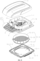
FIG. 14 is an exploded view of an RV sunroof according toEmbodiment 2 of the present disclosure; -
FIG. 15 is a further exploded view ofFIG. 14 ; -
FIG. 16 is a partially enlarged view of E inFIG. 15 ; -
FIG. 17 is a structural stereoscopic view of an RV sunroof from another perspective according toEmbodiment 2 of the present disclosure; -
FIG. 18 is a structural stereoscopic view when a filter screen assembly is detached inFIG. 17 ; -
FIG. 19 is a sectional view of an RV sunroof according toEmbodiment 2 of the present disclosure; -
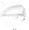
FIG. 20 is a partially enlarged view of F inFIG. 19 ; and -
FIG. 21 is a partially enlarged view of G inFIG. 19 . - In the
figures: 1 : base, 1-1: ventilation duct, 1-2: air intake, 1-3: track, 1-4: first cylindrical portion, 2: outer cover, 3: grille shutter, 3-1: limiting groove, 3-2: guide groove, 3-3: grille hole, 4: avoidance gap, 5: air spring, 6: limiting plate, 7: sealing ring, 8: support rod, 9: roller assembly, 9-1: rolling wheel, 9-2: rotating shaft, 9-3: connecting rod, 9-4: spring, 10: lifting mechanism, 10-1: electric drive structure, 10-1-1: threaded rod, 10-1-2: first cantilever, 10-1-3: second cantilever, 10-1-4: motor, 10-1-5: first slider, 10-1-6: second slider, 10-1-7: supporting seat, 10-2: manual drive structure, 10-2-1: gear set, 10-2-3: handle, 11: upper assembly, 11-16: ventilation fan, 12: lower assembly, 12-1: lower seat, 12-2: filter screen assembly, 12-21: filter screen frame, 12-211: second cylindrical portion, 12-22: filter screen, 12-3: decorative cover, 12-31: side air vent, 12-4: pleated blackout fabric, 13: top plate, α: opening angle of outer cover, and β: inclination angle of grille hole. - The technical solutions of the embodiments of the present disclosure are clearly and completely described below with reference to the drawings in the embodiments of the present disclosure. Apparently, the described embodiments are merely a part rather than all of the embodiments of the present disclosure. The following description of at least one exemplary example is merely illustrative, and not intended to limit the present disclosure and application or use thereof in any way. All other embodiments obtained by a person of ordinary skill in the art on the basis of the embodiments of the present disclosure without creative efforts shall fall within the protection scope of the present disclosure.
- For ease of description, a head direction is used as a front direction in the embodiment. As shown in
FIGS. 1-11 , an air intake structure for a vehicle sunroof includesbase 1,outer cover 2, andgrille shutter 3. A front end of thebase 1 is hinged with a front end of theouter cover 2. Ventilation duct 1-1 is formed in thebase 1 in a penetrating manner. Thegrille shutter 3 is provided below a rear end of theouter cover 2. Thegrille shutter 3 is detachably connected to theouter cover 2. Thegrille shutter 3 is located outside air intake 1-2 of the ventilation duct 1-1. When theouter cover 2 cooperates with thebase 1 to cover the air intake 1-2,avoidance gap 4 is formed between thegrille shutter 3 and thebase 1. When theouter cover 2 rotates away from thebase 1 to open the air intake 1-2, theouter cover 2 drives thegrille shutter 3 to move close to thebase 1, theavoidance gap 4 becomes smaller gradually, and an external airflow sequentially passes through thegrille shutter 3, the air intake 1-2 and the ventilation duct 1-1 to enter a carriage. - In the embodiment, for convenient installation and detachment of the
grille shutter 3, as shown inFIGS. 4-6 , thegrille shutter 3 is detachably connected to theouter cover 2 through bolts. Further, in order to optimize an installation structure of thegrille shutter 3, and make thegrille shutter 3 installed more reliably and stably, a plurality ofsupport rods 8 are fixed at a bottom of theouter cover 2 in the embodiment. The plurality ofsupport rods 8 are sequentially arranged around a periphery of thegrille shutter 3. Thegrille shutter 3 is connected to thesupport rods 8 sequentially by the bolts (not shown in the figure). - In the embodiment, in order to effectively prevent the
outer cover 2 and thegrille shutter 3 from becoming loose or unstable, and avoid an abnormal sound, as shown inFIGS. 4-8 , an end of thegrille shutter 3 close to thebase 1 is provided withroller assembly 9. Theroller assembly 9 includes rolling wheel 9-1. Track 1-3 is provided on thebase 1. The track 1-3 matches with a rotating path of thegrille shutter 3, such that the rolling wheel 9-1 abuts against the track 1-3 all the time during rotation of thegrille shutter 3. Specifically, in the embodiment, theroller assembly 9 further includes rotating shaft 9-2 and connecting rod 9-3. Guide groove 3-2 is formed in thegrille shutter 3. The connecting rod 9-3 includes one end slidably provided in the guide groove 3-2, and the other end connected to the rotating shaft 9-2. The rolling wheel 9-1 is sleeved on the rotating shaft 9-2. Spring 9-4 is provided between an end of the connecting rod 9-3 away from the rotating shaft 9-2 and the guide groove 3-2. The rolling wheel 9-1 is pressed on the track 1-3 all the time under an action of the spring 9-4. Through undulation of the track 1-3, a shaking space of theouter cover 2 in opening and closing is eliminated, and a maximum opening angle of theouter cover 2 is limited. Theroller assembly 9 has a simple and reliable structure, a skillful design, and a stable operation. - In the embodiment, in order to ensure sealing performance of the closed
outer cover 2, and effectively prevent air leakage and water leakage of the sunroof, as shown inFIG. 5 , sealingring 7 is provided at the air intake 1-2. When theouter cover 2 cooperates with thebase 1 to cover the air intake 1-2, theouter cover 2 comes in contact with the sealingring 7. - In the embodiment, as shown in
FIG. 4 ,FIG. 9 andFIG. 10 , the vehicle sunroof further includes liftingmechanism 10. Thelifting mechanism 10 is configured to drive theouter cover 2 to rotate upward to open the ventilation duct 1-1 or rotate downward to close the ventilation duct 1-1. In the embodiment, theouter cover 2 has an opening angle of α, 0°<α≤10°. This not only ensures effective ventilation of the sunroof after theouter cover 2 is opened, but also makes the sunroof reliable, stable, safe and aesthetically-pleasing. Thelifting mechanism 10 includes electric drive structure 10-1 and manual drive structure 10-2. The electric drive structure 10-1 includes threaded rod 10-1-1, first cantilever 10-1-2, second cantilever 10-1-3, and motor 10-1-4. The manual drive structure 10-2 includes gear set 10-2-1 and handle 10-2-3. The threaded rod 10-1-1 is horizontally provided on thebase 1 along a width direction of an RV and located behind the ventilation duct 1-1. A bottom end of the first cantilever 10-1-2 is threadedly connected to the threaded rod 10-1-1 through first slider 10-1-5. A bottom end of the second cantilever 10-1-3 is threadedly connected to the threaded rod 10-1-1 through second slider 10-1-6. A top end of the first cantilever 10-1-2 and a top end of the second cantilever 10-1-3 are hinged to supporting seat 10-1-7. The supporting seat 10-1-7 is connected to theouter cover 2. The first cantilever 10-1-2 intersects with the second cantilever 10-1-3. An output end of the motor 10-1-4 is connected to one end of the threaded rod 10-1-1. An input end of the gear set 10-2-1 is connected to the handle 10-2-3. The handle 10-2-3 is exposed in the vehicle. An output end of the gear set 10-2-1 is connected to an end of the threaded rod 10-1-1 away from the motor 10-1-4. When the threaded rod 10-1-1 rotates, the first cantilever 10-1-2 and the second cantilever 10-1-3 are driven to move close to each other or away from each other. - An RV with a sunroof includes the air intake structure for a vehicle sunroof. The
base 1 is provided at a top of the RV. Both theouter cover 2 and thegrille shutter 3 are exposed out of the RV. - The working principle is as follows:
The air intake structure for a vehicle sunroof is opened as follows:
Theouter cover 2 rotates away from thebase 1 to open the air intake 1-2. Meanwhile, theouter cover 2 drives thegrille shutter 3 to move close to thebase 1, theavoidance gap 4 gradually becomes smaller, and the rolling wheel 9-1 abuts against the track 1-3 all the time under an action of the spring 9-4 during rotation of thegrille shutter 3. When theouter cover 2 is fixed at a certain opening angle, the rolling wheel 9-1 helps support theouter cover 2. In this case, the air intake 1-2 communicates with the outside of the carriage through thegrille shutter 3. The external airflow sequentially passes through thegrille shutter 3, the air intake 1-2 and the ventilation duct 1-1 to enter the carriage. - The air intake structure for a vehicle sunroof is closed as follows:
Theouter cover 2 rotates close to thebase 1. Meanwhile, theouter cover 2 drives thegrille shutter 3 to move away from thebase 1. Theavoidance gap 4 is gradually formed between thegrille shutter 3 and thebase 1. The rolling wheel 9-1 abuts against the track 1-3 all the time under an action of the spring 9-4 during rotation of thegrille shutter 3, until the air intake 1-2 is covered by theouter cover 2, and theouter cover 2 is sealed by the sealingring 7. In this case, the rolling wheel 9-1 helps support theouter cover 2. - The air intake structure for a vehicle sunroof is detached as follows:
Only by screwing down the plurality of bolts between thegrille shutter 3 and thesupport rods 8, thegrille shutter 3 can be taken down. Therefore, thegrille shutter 3 is installed and detached conveniently. Thegrille shutter 3 is taken down conveniently for maintenance such as cleaning. - As shown in
FIGS. 12-21 , the embodiment differs fromEmbodiment 1 in: The vehicle sunroof further includesupper assembly 11 andlower assembly 12. As shown inFIG. 14 ,FIG. 15 ,FIG. 17 andFIG. 18 , thebase 1, theouter cover 2 and thegrille shutter 3 form theupper assembly 11. When theouter cover 2 closes the ventilation duct 1-1, thegrille shutter 3 is horizontally provided, and grille holes 3-3 of thegrille shutter 3 gradually incline forward from bottom to top. As shown inFIG. 14 andFIG. 15 , thelower assembly 12 includes lower seat 12-1 and filter screen assembly 12-2. The ventilation duct 1-1 penetrates through the lower seat 12-1. The filter screen assembly 12-2 includes filter screen frame 12-21 and filter screen 12-22 on the filter screen frame 12-21. The filter screen frame 12-21 is detachably connected to the lower seat 12-1. The filter screen 12-22 is located in the ventilation duct 1-1. As shown inFIG. 13 ,FIG. 14 ,FIG. 19 andFIG. 21 , thebase 1 and the lower seat 12-1 are respectively provided at an upper side and a lower side oftop plate 13 of an RV. A bottom of thebase 1 serves as first cylindrical portion 1-4. A top of the filter screen frame 12-21 serves as second cylindrical portion 12-211. The first cylindrical portion 1-4 and the second cylindrical portion 12-211 are sleeved and are capable of moving along a thickness direction of thetop plate 13. When theouter cover 2 opens the ventilation duct 1-1, the outside, thegrille shutter 3, the ventilation duct 1-1, the filter screen 12-22 and the carriage of the RV are sequentially communicated with each other. - Further, in the embodiment, as shown in
FIG. 20 , the grille holes 3-3 each have an inclination angle of β, the β being in a range of 30° to 60°. The β may be 45°. This ensures smooth connection between the grille hole 3-3 and theouter cover 2 with no obstruction and more smooth airflow in ventilation, and effectively increases a ventilation volume. The grille hole 3-3 has a cross-sectional area of S, the S being in a range of 3.0 cm2 to 3.6 cm2. Optionally, the S is 3.3 cm2. With the appropriate grille hole 3-3, not only is the airflow combed to become smoother and more comfortable, but also sundries, mosquitoes and the like are effectively filtered. In cooperation with the filter screen 12-22, double-layer filtration is realized to effectively prevent the mosquitoes, and make the filtered air clean and fresh. The grille shutter is more aesthetically-pleasing for a small perspective area. - Further, in the embodiment, as shown in
FIG. 13 ,FIG. 14 andFIG. 15 , the lower seat 12-1 is detachably connected to thetop plate 13 through a first bolt, and the filter screen frame 12-21 is detachably connected to the lower seat 12-1 through a second bolt. As shown inFIG. 13 ,FIG. 14 ,FIG. 15 ,FIG. 17 andFIG. 18 , decorative cover 12-3 is provided at a bottom of the lower seat 12-1. The first bolt is fixedly connected to the decorative cover 12-3, the lower seat 12-1 and thetop plate 13 in sequence. While taking protective and dustproof actions, the decorative cover 12-3 is aesthetically-pleasing. Pleated blackout fabric 12-4 is provided in the decorative cover 12-3. Side air vent 12-31 is formed at a side of the decorative cover 12-3. When the pleated blackout fabric 12-4 is unfolded, the pleated blackout fabric 12-4 covers the ventilation duct 1-1, and the side air vent 12-31 communicates with the ventilation duct 1-1 and the carriage of the RV. While taking an aesthetically-pleasing action, the unfolded pleated blackout fabric 12-4 increases an air volume of the side air vent 12-31 and changes an air-out direction. A pattern may be provided on the pleated blackout fabric 12-4 to be more aesthetically-pleasing. - As shown in
FIG. 18 ,FIG. 19 andFIG. 21 , ventilation fan 11-16 is provided in thebase 1 in the embodiment. The ventilation fan 11-16 is located in the ventilation duct 1-1. - The filter screen assembly 12-2 is detached as follows:
Thelower assembly 12 is detached by detaching the first bolt. By detaching the second bolt, the filter screen assembly 12-2 is detached from thelower assembly 12. With convenient detachment, the filter screen 12-22 is repaired, maintained and cleaned conveniently in daily life. Particularly, it is to be noted that since the second cylindrical portion 12-211 of the filter screen frame 12-21 and the first cylindrical portion 1-4 of thebase 1 are sleeved, and can move along the thickness direction of thetop plate 13,top plates 13 with different thicknesses can be matched. That is, thetop plates 13 with the different thicknesses are matched by allowing the second cylindrical portion 12-211 of the filter screen frame 12-21 and the first cylindrical portion 1-4 of thebase 1 to move along the thickness direction of thetop plate 13. In this case, the first cylindrical portion 1-4 and the second cylindrical portion 12-211 are still sleeved to allow the airflow to pass through. - The above described are merely preferred specific implementations of the present disclosure, and the protection scope of the present disclosure is not limited thereto. Any equivalent substitutions or changes made by those skilled in the art according to the technical solutions and concepts of the present disclosure within the technical scope of the present disclosure should be covered by the protection scope of the present disclosure.
Claims (13)
- An air intake structure for a vehicle sunroof, comprising a base (1), an outer cover (2), and a grille shutter (3), wherein a front end of the base (1) is hinged with a front end of the outer cover (2); a ventilation duct (1-1) is formed in the base (1) in a penetrating manner; the grille shutter (3) is provided below a rear end of the outer cover (2); the grille shutter (3) is detachably connected to the outer cover (2); the grille shutter (3) is located outside an air intake (12) of the ventilation duct (1-1); when the outer cover (2) cooperates with the base (1) to cover the air intake (12), an avoidance gap (4) is formed between the grille shutter (3) and the base (1); and when the outer cover (2) rotates away from the base (1) to open the air intake (12), the outer cover (2) drives the grille shutter (3) to move close to the base (1), the avoidance gap (4) becomes smaller gradually, and an external airflow sequentially passes through the grille shutter (3), the air intake (12) and the ventilation duct (1-1) to enter a carriage;an end of the grille shutter (3) close to the base (1) is provided with a roller assembly (9); the roller assembly (9) comprises a rolling wheel (9-1); a track (1-3) is provided on the base (1); and the track (1-3) matches with a rotating path of the grille shutter (3), such that the rolling wheel (9-1) abuts against the track (1-3) all the time during rotation of the grille shutter (3); andthe roller assembly (9) further comprises a rotating shaft (9-2) and a connecting rod (9-3); a guide groove (3-2) is formed in the grille shutter (3); the connecting rod (9-3) comprises one end slidably provided in the guide groove (3-2), and the other end connected to the rotating shaft (9-2); the rolling wheel (9-1) is sleeved on the rotating shaft (9-2); and a spring (9-4) is provided between an end of the connecting rod (9-3) away from the rotating shaft (9-2) and the guide groove (3-2).
- The air intake structure for a vehicle sunroof according to claim 1, wherein the outer cover (2) has an opening angle of α, 0°<α≤10°.
- The air intake structure for a vehicle sunroof according to claim 1, wherein a sealing ring (7) is provided at the air intake (12), and when the outer cover (2) cooperates with the base (1) to cover the air intake (12), the outer cover (2) comes in contact with the sealing ring (7).
- The air intake structure for a vehicle sunroof according to any one of claims 1 to 3, wherein the grille shutter (3) is detachably connected to the outer cover (2) through bolts.
- The air intake structure for a vehicle sunroof according to claim 4, wherein a plurality of support rods (8) are fixed at a bottom of the outer cover (2); the plurality of support rods (8) are sequentially arranged around a periphery of the grille shutter (3); and the grille shutter (3) is connected to the support rods (8) sequentially by the bolts.
- A recreational vehicle (RV) with a sunroof, comprising the air intake structure for a vehicle sunroof according to any one of claims 1 to 5, wherein the base (1) is provided at a top of the RV, and both the outer cover (2) and the grille shutter (3) are exposed out of the RV.
- The air intake structure for a vehicle sunroof according to claim 1, wherein the vehicle sunroof further comprises a lifting mechanism (10); the lifting mechanism (10) is configured to drive the outer cover (2) to rotate upward to open the ventilation duct (1-1) or rotate downward to close the ventilation duct (1-1); the lifting mechanism (10) comprises an electric drive structure (10-1) and a manual drive structure (10-2); the electric drive structure (10-1) comprises a threaded rod (10-1-1), a first cantilever (10-1-2), a second cantilever (10-1-3), and a motor (10-1-4); the manual drive structure (10-2) comprises a gear set (10-2-1) and a handle (10-2-3); the threaded rod (10-1-1) is horizontally provided on the base (1) along a width direction of a recreational vehicle (RV) and located behind the ventilation duct (1-1); a bottom end of the first cantilever (10-1-2) is threadedly connected to the threaded rod (10-1-1) through a first slider (10-1-5); a bottom end of the second cantilever (10-1-3) is threadedly connected to the threaded rod (10-1-1) through a second slider (10-1-6); a top end of the first cantilever (10-1-2) and a top end of the second cantilever (10-1-3) are connected to the outer cover (2) through a supporting seat (10-1-7); the first cantilever (10-1-2) intersects with the second cantilever (10-1-3); an output end of the motor (10-1-4) is connected to one end of the threaded rod (10-1-1); the gear set (10-2-1) comprises an input end connected to the handle (10-2-3), and an output end connected to an end of the threaded rod (10-1-1) away from the motor (10-1-4); and when the threaded rod (10-1-1) rotates, the first cantilever (10-1-2) and the second cantilever (10-1-3) are driven to move close to each other or away from each other.
- The air intake structure for a vehicle sunroof according to claim 1, wherein the vehicle sunroof further comprises an upper assembly (11) and a lower assembly (12); the base (1), the outer cover (2) and the grille shutter (3) form the upper assembly (11); and when the outer cover (2) closes the ventilation duct (1-1), the grille shutter (3) is horizontally provided, and grille holes (3-3) of the grille shutter (3) gradually incline forward from bottom to top;the lower assembly (12) comprises a lower seat (12-1) and a filter screen assembly (12-2); the ventilation duct (1-1) penetrates through the lower seat (12-1); the filter screen assembly (12-2) comprises a filter screen frame (12-21) and a filter screen (12-22) on the filter screen frame (12-21); the filter screen frame (12-21) is detachably connected to the lower seat (12-1); and the filter screen (12-22) is located in the ventilation duct (1-1); andthe base (1) and the lower seat (12-1) are respectively provided at an upper side and a lower side of a top plate (13) of an RV; a bottom of the base (1) serves as a first cylindrical portion (1-4); a top of the filter screen frame (12-21) serves as a second cylindrical portion (12-211); the first cylindrical portion (1-4) and the second cylindrical portion (12-211) are sleeved and arecapable of moving along a thickness direction of the top plate (13); and when the outer cover (2) opens the ventilation duct (1-1), an outside of the RV, the grille shutter (3), the ventilation duct (1-1), the filter screen (12-22), and the carriage of the RV are sequentially communicated with each other.
- The air intake structure for a vehicle sunroof according to claim 8, wherein the grille holes (3-3) each have an inclination angle of β, the β being in a range of 30° to 60°.
- The air intake structure for a vehicle sunroof according to claim 8 or 9, wherein the grille hole (3-3) has a cross-sectional area of S, the S being in a range of 3.0 cm2 to 3.6 cm2.
- The air intake structure for a vehicle sunroof according to claim 8, wherein the lower seat (12-1) is detachably connected to the top plate (13) through a first bolt, and the filter screen frame (12-21) is detachably connected to the lower seat (12-1) through a second bolt.
- The air intake structure for a vehicle sunroof according to claim 11, wherein a decorative cover (12-3) is provided at a bottom of the lower seat (12-1), and the first bolt is fixedly connected to the decorative cover (12-3), the lower seat (12-1) and the top plate (13) in sequence.
- The air intake structure for a vehicle sunroof according to claim 12, wherein a pleated blackout fabric (12-4) is provided in the decorative cover (12-3); a side air vent (12-31) is formed at a side of the decorative cover (12-3); and when the pleated blackout fabric (12-4) is unfolded, the pleated blackout fabric (12-4) covers the ventilation duct (1-1), and the side air vent (12-31) communicates with the ventilation duct (1-1) and the carriage of the RV.
Applications Claiming Priority (2)
| Application Number | Priority Date | Filing Date | Title |
|---|---|---|---|
| CN202310456546.7A CN116198287B (en) | 2023-04-26 | 2023-04-26 | Air inlet structure of automobile skylight and automobile as a house with skylight |
| PCT/CN2023/115140 WO2024221670A1 (en) | 2023-04-26 | 2023-08-28 | Air inlet structure of automotive sunroof, and recreational vehicle with sunroof |
Publications (5)
| Publication Number | Publication Date |
|---|---|
| EP4477434A1 EP4477434A1 (en) | 2024-12-18 |
| EP4477434A4 EP4477434A4 (en) | 2025-02-12 |
| EP4477434A9 true EP4477434A9 (en) | 2025-02-12 |
| EP4477434C0 EP4477434C0 (en) | 2025-10-01 |
| EP4477434B1 EP4477434B1 (en) | 2025-10-01 |
Family
ID=93217005
Family Applications (1)
| Application Number | Title | Priority Date | Filing Date |
|---|---|---|---|
| EP23798325.9A Active EP4477434B1 (en) | 2023-04-26 | 2023-08-28 | Air intake structure for a vehicle sunroof |
Country Status (5)
| Country | Link |
|---|---|
| US (1) | US20240359534A1 (en) |
| EP (1) | EP4477434B1 (en) |
| JP (1) | JP7746422B2 (en) |
| KR (1) | KR20240159453A (en) |
| AU (1) | AU2023263523A1 (en) |
Families Citing this family (2)
| Publication number | Priority date | Publication date | Assignee | Title |
|---|---|---|---|---|
| USD1062584S1 (en) * | 2023-10-30 | 2025-02-18 | Jiangsu Sanjo Intelligent Technology Co., Ltd. | Automotive sunroof |
| KR102828440B1 (en) * | 2024-12-11 | 2025-07-04 | (주)선경이엔티 | Ventilation Device for Camper Vans |
Family Cites Families (12)
| Publication number | Priority date | Publication date | Assignee | Title |
|---|---|---|---|---|
| GB1166200A (en) * | 1967-08-25 | 1969-10-08 | Weathershields Ltd | Improvements in ventilators and windows for vehicles. |
| DE2839786C3 (en) * | 1978-09-13 | 1981-12-17 | Volkswagenwerk Ag, 3180 Wolfsburg | Elevating roof arrangement for a vehicle |
| US4452129A (en) * | 1983-02-28 | 1984-06-05 | Kelley Timothy A | Spring-rodless hingeless ventilator |
| JPS60121911U (en) * | 1984-01-26 | 1985-08-17 | トヨタ車体株式会社 | Vehicle ventilation system |
| JPH022218U (en) * | 1988-06-20 | 1990-01-09 | ||
| DE3903326A1 (en) * | 1989-02-04 | 1990-08-09 | Ziegler Metallwarenfab Emil | SLIDING ROOF FOR A VEHICLE, IN PARTICULAR MOTOR VEHICLE LIKE OMNIBUS, MOTOR VEHICLE AND THE LIKE. |
| US5672101A (en) * | 1991-02-25 | 1997-09-30 | Thomas; Allen C. | Solar operated vent cover |
| US5344361A (en) * | 1992-06-03 | 1994-09-06 | Matthias Jan H | Sun roof vent |
| JP2001180282A (en) * | 1999-12-27 | 2001-07-03 | Webasto Japan Kk | Sunroof |
| US7004832B2 (en) * | 2003-06-02 | 2006-02-28 | Thomas Allen C | Collapsible air vent closure |
| US11027595B2 (en) * | 2016-10-13 | 2021-06-08 | Dometic Sweden Ab | Roof fan assembly |
| US20240010047A1 (en) * | 2022-07-11 | 2024-01-11 | Rivian Ip Holdings, Llc | Venturi ventilator for an enclosure |
-
2023
- 2023-08-28 JP JP2023575350A patent/JP7746422B2/en active Active
- 2023-08-28 AU AU2023263523A patent/AU2023263523A1/en active Pending
- 2023-08-28 EP EP23798325.9A patent/EP4477434B1/en active Active
- 2023-08-28 KR KR1020237035794A patent/KR20240159453A/en active Pending
- 2023-11-06 US US18/387,066 patent/US20240359534A1/en active Pending
Also Published As
| Publication number | Publication date |
|---|---|
| EP4477434A4 (en) | 2025-02-12 |
| US20240359534A1 (en) | 2024-10-31 |
| AU2023263523A1 (en) | 2024-11-14 |
| KR20240159453A (en) | 2024-11-05 |
| JP2025516409A (en) | 2025-05-30 |
| EP4477434C0 (en) | 2025-10-01 |
| AU2023263523A8 (en) | 2025-03-06 |
| JP7746422B2 (en) | 2025-09-30 |
| EP4477434A1 (en) | 2024-12-18 |
| EP4477434B1 (en) | 2025-10-01 |
Similar Documents
| Publication | Publication Date | Title |
|---|---|---|
| EP4477434A9 (en) | Air inlet structure of automotive sunroof, and recreational vehicle with sunroof | |
| KR100928614B1 (en) | cleaner | |
| JP4748249B2 (en) | Air conditioner | |
| CN116638937A (en) | Skylight for motor home | |
| CN101676640B (en) | Air conditioner | |
| WO2024221670A1 (en) | Air inlet structure of automotive sunroof, and recreational vehicle with sunroof | |
| CN214835977U (en) | Sunshade door and window with built-in louver | |
| US6109054A (en) | Air conditioner | |
| JPH1123000A (en) | Air conditioner | |
| JP4165246B2 (en) | Air conditioner | |
| JP2009079833A (en) | Air conditioning device | |
| CN119233137A (en) | Large-scale outdoor stereo set | |
| CN218368253U (en) | Air conditioner ventilation equipment for ship warehouse | |
| CN216121416U (en) | Distribution box capable of automatically removing dust | |
| CN212942026U (en) | Filter cartridge dust remover convenient for replacing filter screen | |
| CN115173248A (en) | Power system control cabinet with insect prevention function | |
| JP2008111580A (en) | Filter cleaning device and air conditioner | |
| JP5216289B2 (en) | Air conditioner | |
| CN210249000U (en) | Dust capturing device for desktop nail beautifying equipment | |
| CN215119599U (en) | Capacitance compensation cabinet with dustproof function | |
| CN112495074B (en) | A kind of flour mill dust suppression equipment and its use method | |
| JP2006214710A (en) | Air conditioner with indoor unit with automatic air filter cleaning function | |
| CN211755274U (en) | Rice mill with dust removal mechanism | |
| CN208003465U (en) | A kind of stage with stage property recycling function | |
| JP2006214721A (en) | Air conditioner |
Legal Events
| Date | Code | Title | Description |
|---|---|---|---|
| STAA | Information on the status of an ep patent application or granted ep patent |
Free format text: STATUS: UNKNOWN |
|
| STAA | Information on the status of an ep patent application or granted ep patent |
Free format text: STATUS: THE INTERNATIONAL PUBLICATION HAS BEEN MADE |
|
| PUAI | Public reference made under article 153(3) epc to a published international application that has entered the european phase |
Free format text: ORIGINAL CODE: 0009012 |
|
| STAA | Information on the status of an ep patent application or granted ep patent |
Free format text: STATUS: REQUEST FOR EXAMINATION WAS MADE |
|
| 17P | Request for examination filed |
Effective date: 20231108 |
|
| AK | Designated contracting states |
Kind code of ref document: A1 Designated state(s): AL AT BE BG CH CY CZ DE DK EE ES FI FR GB GR HR HU IE IS IT LI LT LU LV MC ME MK MT NL NO PL PT RO RS SE SI SK SM TR |
|
| A4 | Supplementary search report drawn up and despatched |
Effective date: 20250115 |
|
| RIC1 | Information provided on ipc code assigned before grant |
Ipc: B60H 1/00 20060101ALI20250109BHEP Ipc: B60H 3/06 20060101ALI20250109BHEP Ipc: B60H 1/24 20060101AFI20250109BHEP |
|
| RIN1 | Information on inventor provided before grant (corrected) |
Inventor name: HU, QINGQING Inventor name: XIAO, HEPING |
|
| REG | Reference to a national code |
Ref country code: DE Ref legal event code: R079 Free format text: PREVIOUS MAIN CLASS: B60H0001240000 Ipc: B60H0001000000 Ref country code: DE Ref legal event code: R079 Ref document number: 602023007195 Country of ref document: DE Free format text: PREVIOUS MAIN CLASS: B60H0001240000 Ipc: B60H0001000000 |
|
| GRAP | Despatch of communication of intention to grant a patent |
Free format text: ORIGINAL CODE: EPIDOSNIGR1 |
|
| STAA | Information on the status of an ep patent application or granted ep patent |
Free format text: STATUS: GRANT OF PATENT IS INTENDED |
|
| RIC1 | Information provided on ipc code assigned before grant |
Ipc: B60J 7/16 20060101ALI20250402BHEP Ipc: B60H 1/26 20060101ALI20250402BHEP Ipc: B60H 1/00 20060101AFI20250402BHEP |
|
| INTG | Intention to grant announced |
Effective date: 20250417 |
|
| GRAS | Grant fee paid |
Free format text: ORIGINAL CODE: EPIDOSNIGR3 |
|
| DAV | Request for validation of the european patent (deleted) | ||
| DAX | Request for extension of the european patent (deleted) | ||
| GRAA | (expected) grant |
Free format text: ORIGINAL CODE: 0009210 |
|
| STAA | Information on the status of an ep patent application or granted ep patent |
Free format text: STATUS: THE PATENT HAS BEEN GRANTED |
|
| AK | Designated contracting states |
Kind code of ref document: B1 Designated state(s): AL AT BE BG CH CY CZ DE DK EE ES FI FR GB GR HR HU IE IS IT LI LT LU LV MC ME MK MT NL NO PL PT RO RS SE SI SK SM TR |
|
| REG | Reference to a national code |
Ref country code: GB Ref legal event code: FG4D Ref country code: CH Ref legal event code: F10 Free format text: ST27 STATUS EVENT CODE: U-0-0-F10-F00 (AS PROVIDED BY THE NATIONAL OFFICE) Effective date: 20251001 |
|
| REG | Reference to a national code |
Ref country code: IE Ref legal event code: FG4D |
|
| REG | Reference to a national code |
Ref country code: DE Ref legal event code: R096 Ref document number: 602023007195 Country of ref document: DE |
|
| U01 | Request for unitary effect filed |
Effective date: 20251013 |
|
| U07 | Unitary effect registered |
Designated state(s): AT BE BG DE DK EE FI FR IT LT LU LV MT NL PT RO SE SI Effective date: 20251017 |