EP4477390A1 - Secondary battery sealing device - Google Patents
Secondary battery sealing device Download PDFInfo
- Publication number
- EP4477390A1 EP4477390A1 EP23750021.0A EP23750021A EP4477390A1 EP 4477390 A1 EP4477390 A1 EP 4477390A1 EP 23750021 A EP23750021 A EP 23750021A EP 4477390 A1 EP4477390 A1 EP 4477390A1
- Authority
- EP
- European Patent Office
- Prior art keywords
- sealing
- pair
- sensing part
- battery case
- sealing parts
- Prior art date
- Legal status (The legal status is an assumption and is not a legal conclusion. Google has not performed a legal analysis and makes no representation as to the accuracy of the status listed.)
- Granted
Links
Images




Classifications
-
- H—ELECTRICITY
- H01—ELECTRIC ELEMENTS
- H01M—PROCESSES OR MEANS, e.g. BATTERIES, FOR THE DIRECT CONVERSION OF CHEMICAL ENERGY INTO ELECTRICAL ENERGY
- H01M50/00—Constructional details or processes of manufacture of the non-active parts of electrochemical cells other than fuel cells, e.g. hybrid cells
- H01M50/10—Primary casings; Jackets or wrappings
- H01M50/102—Primary casings; Jackets or wrappings characterised by their shape or physical structure
- H01M50/105—Pouches or flexible bags
-
- H—ELECTRICITY
- H01—ELECTRIC ELEMENTS
- H01M—PROCESSES OR MEANS, e.g. BATTERIES, FOR THE DIRECT CONVERSION OF CHEMICAL ENERGY INTO ELECTRICAL ENERGY
- H01M10/00—Secondary cells; Manufacture thereof
- H01M10/04—Construction or manufacture in general
- H01M10/0481—Compression means other than compression means for stacks of electrodes and separators
-
- B—PERFORMING OPERATIONS; TRANSPORTING
- B29—WORKING OF PLASTICS; WORKING OF SUBSTANCES IN A PLASTIC STATE IN GENERAL
- B29C—SHAPING OR JOINING OF PLASTICS; SHAPING OF MATERIAL IN A PLASTIC STATE, NOT OTHERWISE PROVIDED FOR; AFTER-TREATMENT OF THE SHAPED PRODUCTS, e.g. REPAIRING
- B29C65/00—Joining or sealing of preformed parts, e.g. welding of plastics materials; Apparatus therefor
- B29C65/02—Joining or sealing of preformed parts, e.g. welding of plastics materials; Apparatus therefor by heating, with or without pressure
- B29C65/18—Joining or sealing of preformed parts, e.g. welding of plastics materials; Apparatus therefor by heating, with or without pressure using heated tools
-
- B—PERFORMING OPERATIONS; TRANSPORTING
- B29—WORKING OF PLASTICS; WORKING OF SUBSTANCES IN A PLASTIC STATE IN GENERAL
- B29C—SHAPING OR JOINING OF PLASTICS; SHAPING OF MATERIAL IN A PLASTIC STATE, NOT OTHERWISE PROVIDED FOR; AFTER-TREATMENT OF THE SHAPED PRODUCTS, e.g. REPAIRING
- B29C66/00—General aspects of processes or apparatus for joining preformed parts
- B29C66/40—General aspects of joining substantially flat articles, e.g. plates, sheets or web-like materials; Making flat seams in tubular or hollow articles; Joining single elements to substantially flat surfaces
- B29C66/41—Joining substantially flat articles ; Making flat seams in tubular or hollow articles
- B29C66/43—Joining a relatively small portion of the surface of said articles
- B29C66/433—Casing-in, i.e. enclosing an element between two sheets by an outlined seam
-
- B—PERFORMING OPERATIONS; TRANSPORTING
- B29—WORKING OF PLASTICS; WORKING OF SUBSTANCES IN A PLASTIC STATE IN GENERAL
- B29C—SHAPING OR JOINING OF PLASTICS; SHAPING OF MATERIAL IN A PLASTIC STATE, NOT OTHERWISE PROVIDED FOR; AFTER-TREATMENT OF THE SHAPED PRODUCTS, e.g. REPAIRING
- B29C66/00—General aspects of processes or apparatus for joining preformed parts
- B29C66/70—General aspects of processes or apparatus for joining preformed parts characterised by the composition, physical properties or the structure of the material of the parts to be joined; Joining with non-plastics material
- B29C66/73—General aspects of processes or apparatus for joining preformed parts characterised by the composition, physical properties or the structure of the material of the parts to be joined; Joining with non-plastics material characterised by the intensive physical properties of the material of the parts to be joined, by the optical properties of the material of the parts to be joined, by the extensive physical properties of the parts to be joined, by the state of the material of the parts to be joined or by the material of the parts to be joined being a thermoplastic or a thermoset
- B29C66/739—General aspects of processes or apparatus for joining preformed parts characterised by the composition, physical properties or the structure of the material of the parts to be joined; Joining with non-plastics material characterised by the intensive physical properties of the material of the parts to be joined, by the optical properties of the material of the parts to be joined, by the extensive physical properties of the parts to be joined, by the state of the material of the parts to be joined or by the material of the parts to be joined being a thermoplastic or a thermoset characterised by the material of the parts to be joined being a thermoplastic or a thermoset
- B29C66/7392—General aspects of processes or apparatus for joining preformed parts characterised by the composition, physical properties or the structure of the material of the parts to be joined; Joining with non-plastics material characterised by the intensive physical properties of the material of the parts to be joined, by the optical properties of the material of the parts to be joined, by the extensive physical properties of the parts to be joined, by the state of the material of the parts to be joined or by the material of the parts to be joined being a thermoplastic or a thermoset characterised by the material of the parts to be joined being a thermoplastic or a thermoset characterised by the material of at least one of the parts being a thermoplastic
- B29C66/73921—General aspects of processes or apparatus for joining preformed parts characterised by the composition, physical properties or the structure of the material of the parts to be joined; Joining with non-plastics material characterised by the intensive physical properties of the material of the parts to be joined, by the optical properties of the material of the parts to be joined, by the extensive physical properties of the parts to be joined, by the state of the material of the parts to be joined or by the material of the parts to be joined being a thermoplastic or a thermoset characterised by the material of the parts to be joined being a thermoplastic or a thermoset characterised by the material of at least one of the parts being a thermoplastic characterised by the materials of both parts being thermoplastics
-
- B—PERFORMING OPERATIONS; TRANSPORTING
- B29—WORKING OF PLASTICS; WORKING OF SUBSTANCES IN A PLASTIC STATE IN GENERAL
- B29C—SHAPING OR JOINING OF PLASTICS; SHAPING OF MATERIAL IN A PLASTIC STATE, NOT OTHERWISE PROVIDED FOR; AFTER-TREATMENT OF THE SHAPED PRODUCTS, e.g. REPAIRING
- B29C66/00—General aspects of processes or apparatus for joining preformed parts
- B29C66/80—General aspects of machine operations or constructions and parts thereof
- B29C66/83—General aspects of machine operations or constructions and parts thereof characterised by the movement of the joining or pressing tools
- B29C66/832—Reciprocating joining or pressing tools
- B29C66/8322—Joining or pressing tools reciprocating along one axis
- B29C66/83221—Joining or pressing tools reciprocating along one axis cooperating reciprocating tools, each tool reciprocating along one axis
-
- B—PERFORMING OPERATIONS; TRANSPORTING
- B29—WORKING OF PLASTICS; WORKING OF SUBSTANCES IN A PLASTIC STATE IN GENERAL
- B29C—SHAPING OR JOINING OF PLASTICS; SHAPING OF MATERIAL IN A PLASTIC STATE, NOT OTHERWISE PROVIDED FOR; AFTER-TREATMENT OF THE SHAPED PRODUCTS, e.g. REPAIRING
- B29C66/00—General aspects of processes or apparatus for joining preformed parts
- B29C66/80—General aspects of machine operations or constructions and parts thereof
- B29C66/87—Auxiliary operations or devices
- B29C66/874—Safety measures or devices
- B29C66/8748—Safety measures or devices involving the use of warnings
-
- B—PERFORMING OPERATIONS; TRANSPORTING
- B29—WORKING OF PLASTICS; WORKING OF SUBSTANCES IN A PLASTIC STATE IN GENERAL
- B29C—SHAPING OR JOINING OF PLASTICS; SHAPING OF MATERIAL IN A PLASTIC STATE, NOT OTHERWISE PROVIDED FOR; AFTER-TREATMENT OF THE SHAPED PRODUCTS, e.g. REPAIRING
- B29C66/00—General aspects of processes or apparatus for joining preformed parts
- B29C66/90—Measuring or controlling the joining process
- B29C66/92—Measuring or controlling the joining process by measuring or controlling the pressure, the force, the mechanical power or the displacement of the joining tools
- B29C66/922—Measuring or controlling the joining process by measuring or controlling the pressure, the force, the mechanical power or the displacement of the joining tools by measuring the pressure, the force, the mechanical power or the displacement of the joining tools
- B29C66/9221—Measuring or controlling the joining process by measuring or controlling the pressure, the force, the mechanical power or the displacement of the joining tools by measuring the pressure, the force, the mechanical power or the displacement of the joining tools by measuring the pressure, the force or the mechanical power
-
- B—PERFORMING OPERATIONS; TRANSPORTING
- B29—WORKING OF PLASTICS; WORKING OF SUBSTANCES IN A PLASTIC STATE IN GENERAL
- B29C—SHAPING OR JOINING OF PLASTICS; SHAPING OF MATERIAL IN A PLASTIC STATE, NOT OTHERWISE PROVIDED FOR; AFTER-TREATMENT OF THE SHAPED PRODUCTS, e.g. REPAIRING
- B29C66/00—General aspects of processes or apparatus for joining preformed parts
- B29C66/90—Measuring or controlling the joining process
- B29C66/92—Measuring or controlling the joining process by measuring or controlling the pressure, the force, the mechanical power or the displacement of the joining tools
- B29C66/924—Measuring or controlling the joining process by measuring or controlling the pressure, the force, the mechanical power or the displacement of the joining tools by controlling or regulating the pressure, the force, the mechanical power or the displacement of the joining tools
- B29C66/9261—Measuring or controlling the joining process by measuring or controlling the pressure, the force, the mechanical power or the displacement of the joining tools by controlling or regulating the pressure, the force, the mechanical power or the displacement of the joining tools by controlling or regulating the displacement of the joining tools
- B29C66/92611—Measuring or controlling the joining process by measuring or controlling the pressure, the force, the mechanical power or the displacement of the joining tools by controlling or regulating the pressure, the force, the mechanical power or the displacement of the joining tools by controlling or regulating the displacement of the joining tools by controlling or regulating the gap between the joining tools
-
- B—PERFORMING OPERATIONS; TRANSPORTING
- B29—WORKING OF PLASTICS; WORKING OF SUBSTANCES IN A PLASTIC STATE IN GENERAL
- B29C—SHAPING OR JOINING OF PLASTICS; SHAPING OF MATERIAL IN A PLASTIC STATE, NOT OTHERWISE PROVIDED FOR; AFTER-TREATMENT OF THE SHAPED PRODUCTS, e.g. REPAIRING
- B29C66/00—General aspects of processes or apparatus for joining preformed parts
- B29C66/90—Measuring or controlling the joining process
- B29C66/92—Measuring or controlling the joining process by measuring or controlling the pressure, the force, the mechanical power or the displacement of the joining tools
- B29C66/924—Measuring or controlling the joining process by measuring or controlling the pressure, the force, the mechanical power or the displacement of the joining tools by controlling or regulating the pressure, the force, the mechanical power or the displacement of the joining tools
- B29C66/9261—Measuring or controlling the joining process by measuring or controlling the pressure, the force, the mechanical power or the displacement of the joining tools by controlling or regulating the pressure, the force, the mechanical power or the displacement of the joining tools by controlling or regulating the displacement of the joining tools
- B29C66/92651—Measuring or controlling the joining process by measuring or controlling the pressure, the force, the mechanical power or the displacement of the joining tools by controlling or regulating the pressure, the force, the mechanical power or the displacement of the joining tools by controlling or regulating the displacement of the joining tools by using stops
- B29C66/92655—Measuring or controlling the joining process by measuring or controlling the pressure, the force, the mechanical power or the displacement of the joining tools by controlling or regulating the pressure, the force, the mechanical power or the displacement of the joining tools by controlling or regulating the displacement of the joining tools by using stops by using several stops
-
- B—PERFORMING OPERATIONS; TRANSPORTING
- B29—WORKING OF PLASTICS; WORKING OF SUBSTANCES IN A PLASTIC STATE IN GENERAL
- B29C—SHAPING OR JOINING OF PLASTICS; SHAPING OF MATERIAL IN A PLASTIC STATE, NOT OTHERWISE PROVIDED FOR; AFTER-TREATMENT OF THE SHAPED PRODUCTS, e.g. REPAIRING
- B29C66/00—General aspects of processes or apparatus for joining preformed parts
- B29C66/90—Measuring or controlling the joining process
- B29C66/96—Measuring or controlling the joining process characterised by the method for implementing the controlling of the joining process
- B29C66/961—Measuring or controlling the joining process characterised by the method for implementing the controlling of the joining process involving a feedback loop mechanism, e.g. comparison with a desired value
-
- H—ELECTRICITY
- H01—ELECTRIC ELEMENTS
- H01M—PROCESSES OR MEANS, e.g. BATTERIES, FOR THE DIRECT CONVERSION OF CHEMICAL ENERGY INTO ELECTRICAL ENERGY
- H01M10/00—Secondary cells; Manufacture thereof
- H01M10/04—Construction or manufacture in general
-
- H—ELECTRICITY
- H01—ELECTRIC ELEMENTS
- H01M—PROCESSES OR MEANS, e.g. BATTERIES, FOR THE DIRECT CONVERSION OF CHEMICAL ENERGY INTO ELECTRICAL ENERGY
- H01M10/00—Secondary cells; Manufacture thereof
- H01M10/04—Construction or manufacture in general
- H01M10/0404—Machines for assembling batteries
-
- B—PERFORMING OPERATIONS; TRANSPORTING
- B29—WORKING OF PLASTICS; WORKING OF SUBSTANCES IN A PLASTIC STATE IN GENERAL
- B29C—SHAPING OR JOINING OF PLASTICS; SHAPING OF MATERIAL IN A PLASTIC STATE, NOT OTHERWISE PROVIDED FOR; AFTER-TREATMENT OF THE SHAPED PRODUCTS, e.g. REPAIRING
- B29C66/00—General aspects of processes or apparatus for joining preformed parts
- B29C66/70—General aspects of processes or apparatus for joining preformed parts characterised by the composition, physical properties or the structure of the material of the parts to be joined; Joining with non-plastics material
- B29C66/71—General aspects of processes or apparatus for joining preformed parts characterised by the composition, physical properties or the structure of the material of the parts to be joined; Joining with non-plastics material characterised by the composition of the plastics material of the parts to be joined
-
- B—PERFORMING OPERATIONS; TRANSPORTING
- B29—WORKING OF PLASTICS; WORKING OF SUBSTANCES IN A PLASTIC STATE IN GENERAL
- B29C—SHAPING OR JOINING OF PLASTICS; SHAPING OF MATERIAL IN A PLASTIC STATE, NOT OTHERWISE PROVIDED FOR; AFTER-TREATMENT OF THE SHAPED PRODUCTS, e.g. REPAIRING
- B29C66/00—General aspects of processes or apparatus for joining preformed parts
- B29C66/70—General aspects of processes or apparatus for joining preformed parts characterised by the composition, physical properties or the structure of the material of the parts to be joined; Joining with non-plastics material
- B29C66/72—General aspects of processes or apparatus for joining preformed parts characterised by the composition, physical properties or the structure of the material of the parts to be joined; Joining with non-plastics material characterised by the structure of the material of the parts to be joined
- B29C66/723—General aspects of processes or apparatus for joining preformed parts characterised by the composition, physical properties or the structure of the material of the parts to be joined; Joining with non-plastics material characterised by the structure of the material of the parts to be joined being multi-layered
- B29C66/7232—General aspects of processes or apparatus for joining preformed parts characterised by the composition, physical properties or the structure of the material of the parts to be joined; Joining with non-plastics material characterised by the structure of the material of the parts to be joined being multi-layered comprising a non-plastics layer
- B29C66/72321—General aspects of processes or apparatus for joining preformed parts characterised by the composition, physical properties or the structure of the material of the parts to be joined; Joining with non-plastics material characterised by the structure of the material of the parts to be joined being multi-layered comprising a non-plastics layer consisting of metals or their alloys
-
- B—PERFORMING OPERATIONS; TRANSPORTING
- B29—WORKING OF PLASTICS; WORKING OF SUBSTANCES IN A PLASTIC STATE IN GENERAL
- B29C—SHAPING OR JOINING OF PLASTICS; SHAPING OF MATERIAL IN A PLASTIC STATE, NOT OTHERWISE PROVIDED FOR; AFTER-TREATMENT OF THE SHAPED PRODUCTS, e.g. REPAIRING
- B29C66/00—General aspects of processes or apparatus for joining preformed parts
- B29C66/90—Measuring or controlling the joining process
- B29C66/96—Measuring or controlling the joining process characterised by the method for implementing the controlling of the joining process
- B29C66/967—Measuring or controlling the joining process characterised by the method for implementing the controlling of the joining process involving special data inputs or special data outputs, e.g. for monitoring purposes
- B29C66/9674—Measuring or controlling the joining process characterised by the method for implementing the controlling of the joining process involving special data inputs or special data outputs, e.g. for monitoring purposes involving special data outputs, e.g. special data display means
-
- B—PERFORMING OPERATIONS; TRANSPORTING
- B29—WORKING OF PLASTICS; WORKING OF SUBSTANCES IN A PLASTIC STATE IN GENERAL
- B29L—INDEXING SCHEME ASSOCIATED WITH SUBCLASS B29C, RELATING TO PARTICULAR ARTICLES
- B29L2031/00—Other particular articles
- B29L2031/34—Electrical apparatus, e.g. sparking plugs or parts thereof
- B29L2031/3468—Batteries, accumulators or fuel cells
-
- B—PERFORMING OPERATIONS; TRANSPORTING
- B29—WORKING OF PLASTICS; WORKING OF SUBSTANCES IN A PLASTIC STATE IN GENERAL
- B29L—INDEXING SCHEME ASSOCIATED WITH SUBCLASS B29C, RELATING TO PARTICULAR ARTICLES
- B29L2031/00—Other particular articles
- B29L2031/712—Containers; Packaging elements or accessories, Packages
- B29L2031/7146—Battery-cases
-
- Y—GENERAL TAGGING OF NEW TECHNOLOGICAL DEVELOPMENTS; GENERAL TAGGING OF CROSS-SECTIONAL TECHNOLOGIES SPANNING OVER SEVERAL SECTIONS OF THE IPC; TECHNICAL SUBJECTS COVERED BY FORMER USPC CROSS-REFERENCE ART COLLECTIONS [XRACs] AND DIGESTS
- Y02—TECHNOLOGIES OR APPLICATIONS FOR MITIGATION OR ADAPTATION AGAINST CLIMATE CHANGE
- Y02E—REDUCTION OF GREENHOUSE GAS [GHG] EMISSIONS, RELATED TO ENERGY GENERATION, TRANSMISSION OR DISTRIBUTION
- Y02E60/00—Enabling technologies; Technologies with a potential or indirect contribution to GHG emissions mitigation
- Y02E60/10—Energy storage using batteries
Definitions
- the present invention relates to an apparatus for sealing a secondary battery, and more particularly, to an apparatus for sealing a secondary battery including a pouch type battery case.
- lithium secondary batteries having high energy density and discharge voltage are much researched, and also are commercialized and widely used.
- the lithium secondary batteries are configured by embedding an electrode assembly in a battery case made of a metal can or a laminate sheet in a state, in which the electrode assembly constituted by a positive electrode, a negative electrode, and a separator interposed between the positive electrode and the negative electrode is stacked or wound, and then injecting or impregnating an electrolyte into the battery case.
- a pouch type secondary battery which has a structure in which a stacked type or stack and folding type electrode assembly is embedded in a pouch type battery case made of a laminate sheet, gradually increases for reasons such as low manufacture cost, light weight, and easy change in shape.
- a battery case S of this pouch type secondary battery is sealed by a sealing apparatus to have a sealing structure in order to prevent external leakage and damage of the electrode assembly and the electrolyte inside the battery case S.
- FIGS. 1A and 1B illustrate that a sealing apparatus 1 according to the related art seals the battery case S.
- the sealing apparatus 1 according to the related art is generally provided in a pair, and the pair of sealing apparatus 1 are disposed at an upper side and a lower side, respectively, of the secondary battery S and then seal the battery case S by applying a fixed temperature and pressure.
- the sealing apparatus 1 may be provided to move vertically toward the secondary battery S, and have a structure which includes a sealing block 2 for pressing the secondary battery S and a protrusion 3 protruding from one surface of the sealing block 2 to have a predetermined height.
- the respective protrusions 3 of the pair of sealing apparatuses 1 are disposed to face each other, as illustrated in FIG. 1A , when each of the sealing apparatuses 1 moves toward the battery case S by a predetermined distance or greater, the respective protrusions 3 of the pair of sealing apparatuses 1 are in contact with each other to limit the movement of the sealing apparatus 1. Accordingly, the battery case may be prevented from being excessively pressed.
- sealing portion of the battery case S is not sufficiently pressed and thus has the thickness that exceeds a predetermined thickness. Accordingly, sealing portions of a plurality battery cases S have nonuniform thicknesses, and processing conditions for initial equipment settings and processing conditions after mass production vary so that processing stability is reduced. Thus, there is a need for the techniques for solving the problems.
- the present invention has been devised to solve the problems as above and an object of the present invention is to provide is to provide an apparatus for sealing a secondary battery, which is capable of maintaining a thickness of a sealing portion of a battery case to be uniform during sealing of the battery case of the secondary battery.
- the present invention provides an apparatus for sealing a secondary battery including: a pair of sealing parts that are disposed to face each other with a battery case, in which an electrode assembly is embedded, interposed therebetween, and are provided so that a distance of gap therebetween is adjustable; and at least one sensing part that is provided between the pair of sealing parts and detects a change in pressure according to a change in the distance of gap between the pair of sealing parts.
- Each of the sealing parts may include a sealing block, which presses and seals a sealing portion of the battery case, and a pair of protrusions which protrude from one surface, which faces the battery case, of the sealing block.
- the respective protrusions of the pair of sealing parts may be disposed to face each other.
- the pair of protrusions may protrude from both ends of the sealing block, respectively.
- the sensing part may be fixed to and installed on each of the protrusions.
- the sensing part may be pressed between the respective protrusions of the pair of sealing parts.
- the sensing part may be fixed to and supported by at least one of the pair of sealing parts.
- the sensing part may include at least one pressure sensor.
- the apparatus for sealing the secondary battery according to the present invention may further include an output interface that outputs an alarm based on a pressure value detected by the sensing part.
- the apparatus for sealing the secondary battery according to the present invention may further include a controller that compares the pressure value obtained by the sensing part with a preset pressure value to control a moving distance of the sealing part.
- the present invention may include the at least one sensing part, which detects the change in pressure according to the change in the distance of gap between the pair of sealing parts, to control the gap between the pair of sealing parts on the basis of the pressure value detected by the sensing part. Accordingly, the present invention has the effect that the thickness of the sealing portion may be ensured to be uniform.
- the present invention provides an apparatus 10 for sealing a secondary battery including a pair of sealing parts 100, which are disposed to face each other with a battery case S, in which an electrode assembly (not shown) is embedded, interposed therebetween and are provided so that a distance of gap therebetween is adjustable, and at least one sensing part 200 which is provided between the pair of sealing parts 100 and detects a change in pressure according to a change in the distance of gap between the pair of sealing parts 100.
- the sealing parts 100 are components, which are disposed to face each other with the battery case S, in which the electrode assembly is embedded, interposed therebetween and are provided so that the distance therebetween is adjustable, and may have various configurations.
- the electrode assembly may have a configuration in which electrodes such as a positive electrode and a negative electrode, and separators are alternately disposed. More specifically, the electrode assembly may have a structure in which a positive electrode collector/a positive electrode active material layer/a separator/a negative electrode active material layer/a negative electrode collector are stacked in sequence and thus, the positive electrode active material layer on one surface of the separator faces the negative electrode active material layer on the other surface of the separator. This electrode assembly may be embedded in the battery case S.
- the battery case S may be sealed by the apparatus 10 for sealing the secondary battery to have a sealing structure in order to prevent the electrode assembly and an electrolyte inside the battery case S from leaking to the outside and to prevent the electrode assembly and the electrolyte from being exposed to the outside to be damaged.
- each of the sealing parts 100 may include a sealing block 110, which presses and seals a sealing portion of the battery case S, and a pair of protrusions 120 which protrude from one surface, which faces the battery case S, of the sealing block 110.
- the sealing block 110 is a component, which presses and seals the sealing portion of the battery case S, and may have various configurations.
- the sealing portion is a portion to be sealed in the battery case S, and may include at least one side of an outer circumference of the battery case S.
- the sealing portion may be provided in a circumferential direction of the battery case S.
- the sealing block 110 may press and seal the sealing portion of the battery case S by moving to the sealing portion.
- the sealing part 100 may additionally include a connecting part 130, which has one end connected to the sealing block 110 and the other end connected to a moving means (not shown) for moving the sealing block 110.
- the moving means may include a driving device such as an actuator.
- the sealing block 110 may additionally include a heating part (not shown) to press and heat the sealing portion at the same time so that the sealing portion is thermally fused.
- the heating part may heat the sealing portion to a temperature higher than the room temperature.
- the room temperature means a range of temperatures, which is called a constant temperature in the relevant field. That is, the room temperature means a temperature inside an experimental room, a laboratory or the like, and particularly, refers to an indoor air temperature as an expression of a temperature condition used when an experiment is carried out without setting or adjusting a temperature or when a specimen and a material are left indoors.
- the room temperature generally refers to a temperature at which humans are comfortable, and is usually about 15°C to about 20°C.
- the temperature higher than the room temperature may be a temperature of 20°C or higher, and more specifically, when a sealing layer to be thermally fused in the sealing portion is made of a polypropylene resin, the temperature higher than the room temperature may be set to 160°C to 190°C.
- the sealing block 110 may have various shapes such as a bar shape.
- the pair of protrusions 120 protruding in one direction may be provided on the one surface of the sealing block 110.
- each of the protrusions 120 is a component that protrudes from the one surface, which faces the battery case S, of the sealing block 110, and may have various configurations.
- the pair of protrusions 120 may protrude from both ends of the sealing block 110, respectively.
- the respective protrusions 120 of the pair of sealing parts 100 may be disposed to face each other.
- At least one of the protrusions 120 disposed to face each other may be in contact with the sensing part 200, which will be described later, to limit the movement of the sealing parts 100.
- the protrusion 120 on which the sensing part 200 is not installed may be in contact with the sensing part 200 to limit the movement of the sealing parts 100.
- the protrusion 120 may prevent the sealing portion of the battery case S from being excessively pressed, and may prevent a thickness of the sealing portion from being less than a preset thickness.
- the thickness may be understood as a height in a Z direction in FIGS. 2A to 3B , and the same may be understood below.
- the apparatus 10 for sealing the secondary battery according to the present invention may include the sensing part 200 so as to prevent the thickness of the sealing portion from exceeding the preset thickness due to insufficiently pressing of the sealing portion of the battery case S.
- This sensing part 200 is a component including at least one sensing part 200, which is provided between the pair of sealing parts 100 and detects a change in pressure according to a change in the distance of gap between the pair of sealing parts 100, and may have various configurations.
- the sensing part 200 may include at least one pressure sensor.
- various types of pressure sensors such as a resonance pressure sensor, a piezoelectric pressure sensor, a strain gauge pressure sensor, and a capacitive pressure sensor, may be used as the pressure sensor.
- the sensing part 200 may be provided between the pair of sealing parts 100 to detect a pressure value varying as soon as the pair of sealing parts 100 are in contact with each other.
- the change in pressure value detected by the sensing part 200 may mean that the sealing portion of the battery case S is being pressed.
- the pressure value detected by the sensing part 200 may be less than a preset pressure value.
- the preset pressure value may be understood as a pressure value detected by the sensing part 200 at time point at which the thickness of the sealing portion of the battery case S has been pressed to the preset thickness.
- the pressure value of the sensing part 200 may not be changed from an initial set value.
- the initial set value is "0"
- the pressure value of the sensing part 200 may be also "0".
- the pressure value of the sensing part 200 is less than the preset pressure value, a user may recognize that the sealing portion of the battery case S is not being sufficiently pressed. Then, the user may control the pair of sealing parts 100 so that a distance between the pair of sealing parts 100 is decreased, to sufficiently press the sealing portion. Accordingly, the thickness of the sealing portion of the battery case S may be adjusted to be uniform.
- This sensing part 200 may be provided between the pair of sealing parts 100, and in this case, the sensing part 200 may be fixed to each of the pair of sealing parts 100 or may be fixed by a separate device provided between the pair of sealing parts 100.
- the sensing part 200 may be fixed to and installed on each of the pair of sealing parts 100 in order to reduce the manufacturing costs and simplify the structure.
- the sensing part 200 may be fixed to and supported by at least one of the pair of sealing parts 100.
- the sensing part 200 may be fixed to and installed on the sealing part 100, which is disposed at a lower side of the battery case S, of the pair of sealing parts 100 as illustrated in FIGS. 2A and 2B .
- the sensing part 200 may be fixed to and installed on the sealing part 100, which is disposed at an upper side of the battery case S, of the pair of sealing parts 100 as illustrated in FIGS. 3A and 3B .
- the sensing part 200 may be fixed to and installed on the protrusion 120. That is, as illustrated in FIGS. 2A and 3B , the sensing part 200 may be pressed between the respective protrusions 120 of the pair of sealing parts 100.
- the apparatus for sealing the secondary battery according to the present invention may further include an output interface 300 that outputs an alarm based on the pressure value detected by the sensing part 200.
- the output interface 300 is a component, which outputs an alarm based on the pressure value detected by the sensing part 200, and may have various configurations.
- the output interface 300 may receive the detected pressure value from the sensing part 200 in a near-field wired communication method such as controller area network (CAN), serial communication, and Ethernet, or a wireless communication method such as Bluetooth, infrared data association, ZigBee, and Wi-Fi, and then output the received pressure value as an image and/or sound.
- a near-field wired communication method such as controller area network (CAN), serial communication, and Ethernet
- a wireless communication method such as Bluetooth, infrared data association, ZigBee, and Wi-Fi
- This output interface 300 may include a display module, which outputs the alarm based on the pressure value as an image, and/or a speaker module, which outputs the alarm based on the pressure value as sound, or the like.
- the apparatus for sealing the secondary battery according to the present invention may further include a controller 400 that compares the pressure value obtained by the sensing part 200 with the preset pressure value to control a moving distance of the sealing part 100.
- the controller 400 is a component, which compares the pressure value obtained by the sensing part 200 with the preset pressure value to control the moving distance of the sealing part 100, and may have various configurations.
- the controller 400 may control the moving distance of the sealing part 100 so that the pair of sealing parts 100 are close to each other.
- the controller 400 may control the moving distance of the sealing part 100 so that the pair of sealing parts 100 are away from each other.
Landscapes
- Engineering & Computer Science (AREA)
- Mechanical Engineering (AREA)
- Chemical & Material Sciences (AREA)
- Chemical Kinetics & Catalysis (AREA)
- Electrochemistry (AREA)
- General Chemical & Material Sciences (AREA)
- Manufacturing & Machinery (AREA)
- Sealing Battery Cases Or Jackets (AREA)
- Secondary Cells (AREA)
Abstract
Description
- The present application claims the benefit of the priority of
Korean Patent Application No. 10-2022-0015838, filed on February 07, 2022 - The present invention relates to an apparatus for sealing a secondary battery, and more particularly, to an apparatus for sealing a secondary battery including a pouch type battery case.
- As the technical development of and a demand for mobile devices increase, a demand for secondary batteries as energy sources rapidly increases. Among the secondary batteries, lithium secondary batteries having high energy density and discharge voltage are much researched, and also are commercialized and widely used.
- In general, the lithium secondary batteries are configured by embedding an electrode assembly in a battery case made of a metal can or a laminate sheet in a state, in which the electrode assembly constituted by a positive electrode, a negative electrode, and a separator interposed between the positive electrode and the negative electrode is stacked or wound, and then injecting or impregnating an electrolyte into the battery case.
- Recently, due to a larger capacity of secondary batteries, processing for manufacturing a case having a large area and made of a thin material attracts a lot of interest. Accordingly, the use of a pouch type secondary battery, which has a structure in which a stacked type or stack and folding type electrode assembly is embedded in a pouch type battery case made of a laminate sheet, gradually increases for reasons such as low manufacture cost, light weight, and easy change in shape.
- A battery case S of this pouch type secondary battery is sealed by a sealing apparatus to have a sealing structure in order to prevent external leakage and damage of the electrode assembly and the electrolyte inside the battery case S.
-
FIGS. 1A and1B illustrate that asealing apparatus 1 according to the related art seals the battery case S. As illustrated inFIGS. 1A and1B , thesealing apparatus 1 according to the related art is generally provided in a pair, and the pair ofsealing apparatus 1 are disposed at an upper side and a lower side, respectively, of the secondary battery S and then seal the battery case S by applying a fixed temperature and pressure. - Specifically, the
sealing apparatus 1 according to the related art may be provided to move vertically toward the secondary battery S, and have a structure which includes asealing block 2 for pressing the secondary battery S and aprotrusion 3 protruding from one surface of thesealing block 2 to have a predetermined height. - In particular, as the
respective protrusions 3 of the pair ofsealing apparatuses 1 are disposed to face each other, as illustrated inFIG. 1A , when each of thesealing apparatuses 1 moves toward the battery case S by a predetermined distance or greater, therespective protrusions 3 of the pair ofsealing apparatuses 1 are in contact with each other to limit the movement of thesealing apparatus 1. Accordingly, the battery case may be prevented from being excessively pressed. - As illustrated in
FIG. 1B , however, when a sealing portion of the battery case S has an initial thickness equal to or larger than a certain level due to a tolerance of a sealing material or the like, therespective protrusions 3 of the pair ofsealing apparatuses 1 fail to be in contact with each other and are spaced at a predetermined gap G from each other. Accordingly, in the related art, a user checks the gap G between theprotrusions 3 through the naked eyes to adjust a gap between thesealing apparatuses 1. However, there is a problem that when the gap G between theprotrusions 3 is difficult to check through the naked eyes, the user has difficulty in noticing the abnormal condition. - This cause a problem that the sealing portion of the battery case S is not sufficiently pressed and thus has the thickness that exceeds a predetermined thickness. Accordingly, sealing portions of a plurality battery cases S have nonuniform thicknesses, and processing conditions for initial equipment settings and processing conditions after mass production vary so that processing stability is reduced. Thus, there is a need for the techniques for solving the problems.
- The present invention has been devised to solve the problems as above and an object of the present invention is to provide is to provide an apparatus for sealing a secondary battery, which is capable of maintaining a thickness of a sealing portion of a battery case to be uniform during sealing of the battery case of the secondary battery.
- The present invention provides an apparatus for sealing a secondary battery including: a pair of sealing parts that are disposed to face each other with a battery case, in which an electrode assembly is embedded, interposed therebetween, and are provided so that a distance of gap therebetween is adjustable; and at least one sensing part that is provided between the pair of sealing parts and detects a change in pressure according to a change in the distance of gap between the pair of sealing parts.
- Each of the sealing parts may include a sealing block, which presses and seals a sealing portion of the battery case, and a pair of protrusions which protrude from one surface, which faces the battery case, of the sealing block.
- The respective protrusions of the pair of sealing parts may be disposed to face each other.
- The pair of protrusions may protrude from both ends of the sealing block, respectively.
- The sensing part may be fixed to and installed on each of the protrusions.
- The sensing part may be pressed between the respective protrusions of the pair of sealing parts.
- The sensing part may be fixed to and supported by at least one of the pair of sealing parts.
- The sensing part may include at least one pressure sensor.
- The apparatus for sealing the secondary battery according to the present invention may further include an output interface that outputs an alarm based on a pressure value detected by the sensing part.
- In addition, the apparatus for sealing the secondary battery according to the present invention may further include a controller that compares the pressure value obtained by the sensing part with a preset pressure value to control a moving distance of the sealing part.
- The present invention may include the at least one sensing part, which detects the change in pressure according to the change in the distance of gap between the pair of sealing parts, to control the gap between the pair of sealing parts on the basis of the pressure value detected by the sensing part. Accordingly, the present invention has the effect that the thickness of the sealing portion may be ensured to be uniform.
-
-
FIG. 1A is a conceptual view illustrating that a pair of apparatuses for sealing a secondary battery seal a battery case according to the related art. -
FIG. 1B is a conceptual view illustrating that the apparatuses for sealing the secondary battery inFIG. 1A seal the battery case in a state of failing to be in contact with each other. -
FIG. 2A is a conceptual view illustrating a state in which a pair of apparatuses for sealing a secondary battery are spaced apart from each other according toEmbodiment 1 of the present invention. -
FIG. 2B is a conceptual view illustrating a state in which the pair of apparatuses for sealing the secondary battery inFIG. 2A are in contact with each other to seal a battery cell. -
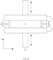
FIG. 3A is a conceptual view illustrating a state in which a pair of apparatuses for sealing a secondary battery are spaced apart from each other according toEmbodiment 2 of the present invention. -
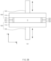
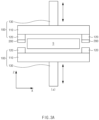
FIG. 3B is a conceptual view illustrating a state in which the pair of apparatuses for sealing the secondary battery inFIG. 3A are in contact with each other to seal a battery cell. -
FIG. 4 is a schematic view illustrating an apparatus for sealing a secondary battery according toEmbodiment 3 of the present invention. - Hereinafter, preferred embodiments of the present invention will be described in detail with reference to the accompanying drawings to enable those skilled in the art to which the present invention pertains to easily carry out the present invention. The present invention may, however, be embodied in different forms and should not be construed as limited by the embodiments set forth herein.
- The parts unrelated to the description, or the detailed descriptions of related well-known art that may unnecessarily obscure subject matters of the present invention, will be ruled out in order to clearly describe the present invention. Like reference numerals refer to like elements throughout the whole specification.
- Moreover, terms or words used in this specification and claims should not be restrictively interpreted as ordinary meanings or dictionary-based meanings, but should be interpreted as meanings and concepts conforming to the scope of the present invention on the basis of the principle that an inventor can properly define the concept of a term to describe and explain his or her invention in the best ways.
- The present invention provides an
apparatus 10 for sealing a secondary battery including a pair ofsealing parts 100, which are disposed to face each other with a battery case S, in which an electrode assembly (not shown) is embedded, interposed therebetween and are provided so that a distance of gap therebetween is adjustable, and at least one sensingpart 200 which is provided between the pair ofsealing parts 100 and detects a change in pressure according to a change in the distance of gap between the pair ofsealing parts 100. - Specifically, the
sealing parts 100 are components, which are disposed to face each other with the battery case S, in which the electrode assembly is embedded, interposed therebetween and are provided so that the distance therebetween is adjustable, and may have various configurations. - Here, the electrode assembly may have a configuration in which electrodes such as a positive electrode and a negative electrode, and separators are alternately disposed. More specifically, the electrode assembly may have a structure in which a positive electrode collector/a positive electrode active material layer/a separator/a negative electrode active material layer/a negative electrode collector are stacked in sequence and thus, the positive electrode active material layer on one surface of the separator faces the negative electrode active material layer on the other surface of the separator. This electrode assembly may be embedded in the battery case S.
- The battery case S may be sealed by the
apparatus 10 for sealing the secondary battery to have a sealing structure in order to prevent the electrode assembly and an electrolyte inside the battery case S from leaking to the outside and to prevent the electrode assembly and the electrolyte from being exposed to the outside to be damaged. - For example, each of the sealing
parts 100 may include asealing block 110, which presses and seals a sealing portion of the battery case S, and a pair ofprotrusions 120 which protrude from one surface, which faces the battery case S, of thesealing block 110. - Here, the sealing
block 110 is a component, which presses and seals the sealing portion of the battery case S, and may have various configurations. Here, the sealing portion is a portion to be sealed in the battery case S, and may include at least one side of an outer circumference of the battery case S. For example, the sealing portion may be provided in a circumferential direction of the battery case S. - Specifically, the sealing
block 110 may press and seal the sealing portion of the battery case S by moving to the sealing portion. Here, the sealingpart 100 may additionally include a connectingpart 130, which has one end connected to thesealing block 110 and the other end connected to a moving means (not shown) for moving thesealing block 110. Here, the moving means may include a driving device such as an actuator. - The sealing
block 110 may additionally include a heating part (not shown) to press and heat the sealing portion at the same time so that the sealing portion is thermally fused. The heating part may heat the sealing portion to a temperature higher than the room temperature. - Here, the room temperature means a range of temperatures, which is called a constant temperature in the relevant field. That is, the room temperature means a temperature inside an experimental room, a laboratory or the like, and particularly, refers to an indoor air temperature as an expression of a temperature condition used when an experiment is carried out without setting or adjusting a temperature or when a specimen and a material are left indoors. The room temperature generally refers to a temperature at which humans are comfortable, and is usually about 15°C to about 20°C.
- Accordingly, the temperature higher than the room temperature may be a temperature of 20°C or higher, and more specifically, when a sealing layer to be thermally fused in the sealing portion is made of a polypropylene resin, the temperature higher than the room temperature may be set to 160°C to 190°C.
- The sealing
block 110 may have various shapes such as a bar shape. Here, as illustrated inFIGS. 2A to 3B , the pair ofprotrusions 120 protruding in one direction may be provided on the one surface of thesealing block 110. - Specifically, each of the
protrusions 120 is a component that protrudes from the one surface, which faces the battery case S, of thesealing block 110, and may have various configurations. In more detail, the pair ofprotrusions 120 may protrude from both ends of thesealing block 110, respectively. Here, therespective protrusions 120 of the pair of sealingparts 100 may be disposed to face each other. - That is, when the pair of sealing
parts 100 move toward the battery case S by a predetermined distance or greater, at least one of theprotrusions 120 disposed to face each other may be in contact with thesensing part 200, which will be described later, to limit the movement of the sealingparts 100. - For example, when the
sensing part 200 to be described later is fixed to and installed on any one of theprotrusions 120 disposed to face each other as illustrated inFIGS. 2A to 3B , theprotrusion 120 on which thesensing part 200 is not installed may be in contact with thesensing part 200 to limit the movement of the sealingparts 100. - Accordingly, the
protrusion 120 may prevent the sealing portion of the battery case S from being excessively pressed, and may prevent a thickness of the sealing portion from being less than a preset thickness. Here, the thickness may be understood as a height in a Z direction inFIGS. 2A to 3B , and the same may be understood below. - The
apparatus 10 for sealing the secondary battery according to the present invention may include thesensing part 200 so as to prevent the thickness of the sealing portion from exceeding the preset thickness due to insufficiently pressing of the sealing portion of the battery case S. - This
sensing part 200 is a component including at least onesensing part 200, which is provided between the pair of sealingparts 100 and detects a change in pressure according to a change in the distance of gap between the pair of sealingparts 100, and may have various configurations. - For example, the
sensing part 200 may include at least one pressure sensor. Here, various types of pressure sensors such as a resonance pressure sensor, a piezoelectric pressure sensor, a strain gauge pressure sensor, and a capacitive pressure sensor, may be used as the pressure sensor. - Specifically, the
sensing part 200 may be provided between the pair of sealingparts 100 to detect a pressure value varying as soon as the pair of sealingparts 100 are in contact with each other. Here, the change in pressure value detected by thesensing part 200 may mean that the sealing portion of the battery case S is being pressed. - When the pair of sealing
parts 100 move by a distance less than a predetermined distance and thus fail to sufficiently press thesensing part 200 or fail to be in contact with thesensing part 200, the pressure value detected by thesensing part 200 may be less than a preset pressure value. Here, the preset pressure value may be understood as a pressure value detected by thesensing part 200 at time point at which the thickness of the sealing portion of the battery case S has been pressed to the preset thickness. - For example, when the
sensing part 200 fails to be in contact with the pair of sealingparts 100, the pressure value of thesensing part 200 may not be changed from an initial set value. Here, when the initial set value is "0", the pressure value of thesensing part 200 may be also "0". - That is, when the pressure value of the
sensing part 200 is less than the preset pressure value, a user may recognize that the sealing portion of the battery case S is not being sufficiently pressed. Then, the user may control the pair of sealingparts 100 so that a distance between the pair of sealingparts 100 is decreased, to sufficiently press the sealing portion. Accordingly, the thickness of the sealing portion of the battery case S may be adjusted to be uniform. - This
sensing part 200 may be provided between the pair of sealingparts 100, and in this case, thesensing part 200 may be fixed to each of the pair of sealingparts 100 or may be fixed by a separate device provided between the pair of sealingparts 100. - Preferably, the
sensing part 200 may be fixed to and installed on each of the pair of sealingparts 100 in order to reduce the manufacturing costs and simplify the structure. In this case, thesensing part 200 may be fixed to and supported by at least one of the pair of sealingparts 100. - As one example, the
sensing part 200 may be fixed to and installed on the sealingpart 100, which is disposed at a lower side of the battery case S, of the pair of sealingparts 100 as illustrated inFIGS. 2A and2B . As another example, thesensing part 200 may be fixed to and installed on the sealingpart 100, which is disposed at an upper side of the battery case S, of the pair of sealingparts 100 as illustrated inFIGS. 3A and3B . - Here, preferably the
sensing part 200 may be fixed to and installed on theprotrusion 120. That is, as illustrated inFIGS. 2A and3B , thesensing part 200 may be pressed between therespective protrusions 120 of the pair of sealingparts 100. - The apparatus for sealing the secondary battery according to the present invention, as illustrated in
FIG. 4 , may further include anoutput interface 300 that outputs an alarm based on the pressure value detected by thesensing part 200. - Specifically, the
output interface 300 is a component, which outputs an alarm based on the pressure value detected by thesensing part 200, and may have various configurations. - For example, the
output interface 300 may receive the detected pressure value from thesensing part 200 in a near-field wired communication method such as controller area network (CAN), serial communication, and Ethernet, or a wireless communication method such as Bluetooth, infrared data association, ZigBee, and Wi-Fi, and then output the received pressure value as an image and/or sound. - This
output interface 300 may include a display module, which outputs the alarm based on the pressure value as an image, and/or a speaker module, which outputs the alarm based on the pressure value as sound, or the like. - The apparatus for sealing the secondary battery according to the present invention may further include a
controller 400 that compares the pressure value obtained by thesensing part 200 with the preset pressure value to control a moving distance of the sealingpart 100. - Specifically, the
controller 400 is a component, which compares the pressure value obtained by thesensing part 200 with the preset pressure value to control the moving distance of the sealingpart 100, and may have various configurations. - For example, when the pressure value detected by the
sensing part 200 is less than the preset pressure value, thecontroller 400 may control the moving distance of the sealingpart 100 so that the pair of sealingparts 100 are close to each other. - Of course, when the pressure value detected by the
sensing part 200 is greater than the preset pressure value, thecontroller 400 may control the moving distance of the sealingpart 100 so that the pair of sealingparts 100 are away from each other. - Although the present invention has been described with reference to the limited embodiments and drawings, the present invention is not limited thereto and may be variously implemented by those of ordinary skill in the art to which the present invention pertains, within the technical idea of the present invention and an equivalent of the appended claims.
-
- 10:
- Apparatus for sealing secondary battery
- 100:
- Sealing part
- 110:
- Sealing block
- 120:
- Protrusion
- 130:
- Connecting part
- 200:
- Sensing part
- 300:
- Output interface
- 400:
- Controller
Claims (10)
- An apparatus for sealing a secondary battery, comprising:a pair of sealing parts disposed to face each other with a battery case, in which an electrode assembly is embedded, interposed therebetween, and provided so that a distance of gap therebetween is adjustable; andat least one sensing part provided between the pair of sealing parts and configured to detect a change in pressure according to a change in the distance of gap between the pair of sealing parts.
- The apparatus of claim 1, wherein each of the sealing parts comprises:a sealing block configured to press and seal a sealing portion of the battery case; anda pair of protrusions protruding from one surface, which face the battery case, of the sealing block.
- The apparatus of claim 2, wherein the respective protrusions of the pair of sealing parts are disposed to face each other.
- The apparatus of claim 2, wherein the pair of protrusions protrude from both ends of the sealing block, respectively.
- The apparatus of claim 2, wherein the sensing part is fixed to and installed on each of the protrusions.
- The apparatus of claim 2, wherein the sensing part is pressed between the respective protrusions of the pair of sealing parts.
- The apparatus of claim 1, wherein the sensing part is fixed to and supported by at least one of the pair of sealing parts.
- The apparatus of claim 1, wherein the sensing part comprises at least one pressure sensor.
- The apparatus of claim 1, further comprising an output interface configured to output an alarm based on a pressure value detected by the sensing part.
- The apparatus of claim 1, further comprising a controller configured to compare the pressure value obtained by the sensing part with a preset pressure value to control a moving distance of the sealing part.
Applications Claiming Priority (2)
| Application Number | Priority Date | Filing Date | Title |
|---|---|---|---|
| KR1020220015838A KR20230119554A (en) | 2022-02-07 | 2022-02-07 | Secondary battery sealing device |
| PCT/KR2023/001753 WO2023149789A1 (en) | 2022-02-07 | 2023-02-07 | Secondary battery sealing device |
Publications (3)
| Publication Number | Publication Date |
|---|---|
| EP4477390A1 true EP4477390A1 (en) | 2024-12-18 |
| EP4477390A4 EP4477390A4 (en) | 2025-05-28 |
| EP4477390B1 EP4477390B1 (en) | 2025-11-26 |
Family
ID=87552664
Family Applications (1)
| Application Number | Title | Priority Date | Filing Date |
|---|---|---|---|
| EP23750021.0A Active EP4477390B1 (en) | 2022-02-07 | 2023-02-07 | Secondary battery sealing device |
Country Status (7)
| Country | Link |
|---|---|
| US (1) | US20260011768A1 (en) |
| EP (1) | EP4477390B1 (en) |
| JP (1) | JP7831741B2 (en) |
| KR (1) | KR20230119554A (en) |
| CN (1) | CN118679048A (en) |
| ES (1) | ES3064016T3 (en) |
| WO (1) | WO2023149789A1 (en) |
Families Citing this family (3)
| Publication number | Priority date | Publication date | Assignee | Title |
|---|---|---|---|---|
| KR20250037124A (en) | 2023-09-08 | 2025-03-17 | 주식회사 엘지화학 | Method for preparing isopropyl alcohol |
| KR20250098381A (en) * | 2023-12-22 | 2025-07-01 | 주식회사 엘지에너지솔루션 | Battery Cell Sealing Device Comprising Gap Measuring Part |
| KR20260001425A (en) * | 2024-06-27 | 2026-01-05 | 주식회사 엘지에너지솔루션 | Pressing device for pouch-type secondary battery and pressing method using the same |
Family Cites Families (12)
| Publication number | Priority date | Publication date | Assignee | Title |
|---|---|---|---|---|
| JP2006108162A (en) * | 2004-09-30 | 2006-04-20 | Sumitomo Osaka Cement Co Ltd | Hermetic sealing method, hermetic sealing body using the method, and heating apparatus used in the method |
| JP2010003763A (en) * | 2008-06-18 | 2010-01-07 | Adwelds:Kk | Package sealing method and package |
| CN101465217B (en) * | 2009-01-08 | 2011-04-20 | 东南大学 | Encapsulation equipment for dye sensitization solar battery |
| JP5911324B2 (en) * | 2012-02-07 | 2016-04-27 | キヤノン株式会社 | Apparatus and method for thermal welding of thermoplastic resin |
| JP6318577B2 (en) * | 2013-11-25 | 2018-05-09 | 日産自動車株式会社 | Sealing part manufacturing apparatus and manufacturing method |
| KR101783923B1 (en) * | 2014-11-26 | 2017-10-10 | 주식회사 엘지화학 | Apparatus and Method of Measuring Thickness of Secondary Battery Cell |
| KR101852250B1 (en) * | 2015-04-02 | 2018-04-26 | 주식회사 엘지화학 | Sealing tool for a pouch type secondary battery |
| KR102240019B1 (en) * | 2019-07-24 | 2021-04-14 | 주식회사 클레버 | Pressing device for sealing secondary battery |
| KR102779856B1 (en) * | 2020-02-13 | 2025-03-12 | 주식회사 엘지에너지솔루션 | Pressing device and pressing method for secondary battery |
| KR20220015838A (en) | 2020-07-31 | 2022-02-08 | 코닝 인코포레이티드 | Apparatus and method for cutting glass laminated substrate |
| CN116487722A (en) * | 2021-07-16 | 2023-07-25 | 广东嘉尚新能源科技有限公司 | A sealing device for soft-packed lithium batteries with detection and recovery functions |
| JP7647460B2 (en) * | 2021-09-10 | 2025-03-18 | 株式会社豊田自動織機 | Manufacturing method of energy storage module |
-
2022
- 2022-02-07 KR KR1020220015838A patent/KR20230119554A/en active Pending
-
2023
- 2023-02-07 ES ES23750021T patent/ES3064016T3/en active Active
- 2023-02-07 US US18/836,202 patent/US20260011768A1/en active Pending
- 2023-02-07 EP EP23750021.0A patent/EP4477390B1/en active Active
- 2023-02-07 WO PCT/KR2023/001753 patent/WO2023149789A1/en not_active Ceased
- 2023-02-07 JP JP2024546476A patent/JP7831741B2/en active Active
- 2023-02-07 CN CN202380020593.5A patent/CN118679048A/en active Pending
Also Published As
| Publication number | Publication date |
|---|---|
| WO2023149789A1 (en) | 2023-08-10 |
| EP4477390A4 (en) | 2025-05-28 |
| CN118679048A (en) | 2024-09-20 |
| US20260011768A1 (en) | 2026-01-08 |
| KR20230119554A (en) | 2023-08-16 |
| EP4477390B1 (en) | 2025-11-26 |
| ES3064016T3 (en) | 2026-04-22 |
| JP2025504187A (en) | 2025-02-06 |
| JP7831741B2 (en) | 2026-03-17 |
Similar Documents
| Publication | Publication Date | Title |
|---|---|---|
| EP4477390B1 (en) | Secondary battery sealing device | |
| KR101763980B1 (en) | Sealiing tool of pouch type secondary battery | |
| KR101838334B1 (en) | A Manufacturing Method for Curved Cell and a Curved Cell thereby | |
| KR102843785B1 (en) | Sealing device for rechargeable battery | |
| US12355056B2 (en) | Apparatus for manufacturing electrode assembly, electrode assembly manufactured therethrough, and secondary battery | |
| EP4120413A1 (en) | Electrode cutting device and electrode manufacturing device comprising same | |
| EP4293772A1 (en) | Zigzag stacking device | |
| KR101840859B1 (en) | Apparatus for Attaching the Adhesion Member for Fixing Battery Assembly | |
| KR101822063B1 (en) | Secondary battery pressing device and electrolyte injection device comprising the same | |
| JP2013506969A5 (en) | ||
| EP4318775A1 (en) | Separator thickness adjusting device and method, and wound electrode assembly production system | |
| EP4290633A1 (en) | Secondary battery defect inspection device and defect inspection method | |
| US20240413372A1 (en) | Method And Apparatus For Manufacturing Unit Cell | |
| US12576626B2 (en) | Laminator for manufacture of unit structural bodies with increased force of adhesion | |
| KR20180044769A (en) | A method of making stacked and folded cells | |
| KR102364600B1 (en) | Sealing apparatus for sealing part of battery cell | |
| KR20230140283A (en) | Secondary battery inspection device and secondary battery inspection method using the same | |
| KR101535712B1 (en) | A Stacking device of Large Capacity Lithium Battery and method thereof | |
| KR102722637B1 (en) | A methode for manufacturing cylindrical secondary battery | |
| KR20240062119A (en) | Heating device for electrode sheet, heating method for electrode sheet and jelly-roll type electrode assembly | |
| KR20230052372A (en) | Battery cell folding system | |
| KR20240032666A (en) | Sealing apparatus for secondary battery | |
| CN117157789A (en) | Electrode assembly and battery cell including the same | |
| CN115917811A (en) | Separator sealing device and equipment for manufacturing unit cells using the same | |
| KR20230060931A (en) | Apparatus and method for slitting target |
Legal Events
| Date | Code | Title | Description |
|---|---|---|---|
| STAA | Information on the status of an ep patent application or granted ep patent |
Free format text: STATUS: THE INTERNATIONAL PUBLICATION HAS BEEN MADE |
|
| PUAI | Public reference made under article 153(3) epc to a published international application that has entered the european phase |
Free format text: ORIGINAL CODE: 0009012 |
|
| STAA | Information on the status of an ep patent application or granted ep patent |
Free format text: STATUS: REQUEST FOR EXAMINATION WAS MADE |
|
| 17P | Request for examination filed |
Effective date: 20240731 |
|
| AK | Designated contracting states |
Kind code of ref document: A1 Designated state(s): AL AT BE BG CH CY CZ DE DK EE ES FI FR GB GR HR HU IE IS IT LI LT LU LV MC ME MK MT NL NO PL PT RO RS SE SI SK SM TR |
|
| REG | Reference to a national code |
Ref country code: DE Ref legal event code: R079 Free format text: PREVIOUS MAIN CLASS: B29C0065000000 Ipc: B29C0065180000 Ref country code: DE Ref legal event code: R079 Ref document number: 602023009067 Country of ref document: DE Free format text: PREVIOUS MAIN CLASS: B29C0065000000 Ipc: B29C0065180000 |
|
| DAV | Request for validation of the european patent (deleted) | ||
| DAX | Request for extension of the european patent (deleted) | ||
| A4 | Supplementary search report drawn up and despatched |
Effective date: 20250428 |
|
| RIC1 | Information provided on ipc code assigned before grant |
Ipc: B29L 31/34 20060101ALN20250422BHEP Ipc: H01M 50/105 20210101ALI20250422BHEP Ipc: H01M 10/04 20060101ALI20250422BHEP Ipc: B29L 31/00 20060101ALI20250422BHEP Ipc: B29C 65/18 20060101AFI20250422BHEP |
|
| GRAP | Despatch of communication of intention to grant a patent |
Free format text: ORIGINAL CODE: EPIDOSNIGR1 |
|
| RIC1 | Information provided on ipc code assigned before grant |
Ipc: B29C 65/18 20060101AFI20250808BHEP Ipc: H01M 10/04 20060101ALI20250808BHEP Ipc: H01M 50/105 20210101ALI20250808BHEP Ipc: B29L 31/00 20060101ALN20250808BHEP Ipc: B29L 31/34 20060101ALN20250808BHEP |
|
| STAA | Information on the status of an ep patent application or granted ep patent |
Free format text: STATUS: GRANT OF PATENT IS INTENDED |
|
| RIC1 | Information provided on ipc code assigned before grant |
Ipc: B29C 65/18 20060101AFI20250903BHEP Ipc: H01M 10/04 20060101ALI20250903BHEP Ipc: H01M 50/105 20210101ALI20250903BHEP Ipc: B29L 31/00 20060101ALN20250903BHEP Ipc: B29L 31/34 20060101ALN20250903BHEP |
|
| GRAS | Grant fee paid |
Free format text: ORIGINAL CODE: EPIDOSNIGR3 |
|
| INTG | Intention to grant announced |
Effective date: 20250918 |
|
| GRAA | (expected) grant |
Free format text: ORIGINAL CODE: 0009210 |
|
| STAA | Information on the status of an ep patent application or granted ep patent |
Free format text: STATUS: THE PATENT HAS BEEN GRANTED |
|
| P01 | Opt-out of the competence of the unified patent court (upc) registered |
Free format text: CASE NUMBER: UPC_APP_8976_4477390/2025 Effective date: 20251006 |
|
| AK | Designated contracting states |
Kind code of ref document: B1 Designated state(s): AL AT BE BG CH CY CZ DE DK EE ES FI FR GB GR HR HU IE IS IT LI LT LU LV MC ME MK MT NL NO PL PT RO RS SE SI SK SM TR |
|
| REG | Reference to a national code |
Ref country code: CH Ref legal event code: F10 Free format text: ST27 STATUS EVENT CODE: U-0-0-F10-F00 (AS PROVIDED BY THE NATIONAL OFFICE) Effective date: 20251126 Ref country code: GB Ref legal event code: FG4D |
|
| REG | Reference to a national code |
Ref country code: IE Ref legal event code: FG4D |
|
| REG | Reference to a national code |
Ref country code: DE Ref legal event code: R096 Ref document number: 602023009067 Country of ref document: DE |
|
| REG | Reference to a national code |
Ref country code: NL Ref legal event code: MP Effective date: 20251126 |
|
| PGFP | Annual fee paid to national office [announced via postgrant information from national office to epo] |
Ref country code: ES Payment date: 20260324 Year of fee payment: 4 |
|
| REG | Reference to a national code |
Ref country code: LT Ref legal event code: MG9D |
|
| PG25 | Lapsed in a contracting state [announced via postgrant information from national office to epo] |
Ref country code: NO Free format text: LAPSE BECAUSE OF FAILURE TO SUBMIT A TRANSLATION OF THE DESCRIPTION OR TO PAY THE FEE WITHIN THE PRESCRIBED TIME-LIMIT Effective date: 20260226 |
|
| PGFP | Annual fee paid to national office [announced via postgrant information from national office to epo] |
Ref country code: DE Payment date: 20260120 Year of fee payment: 4 |
|
| PG25 | Lapsed in a contracting state [announced via postgrant information from national office to epo] |
Ref country code: AT Free format text: LAPSE BECAUSE OF FAILURE TO SUBMIT A TRANSLATION OF THE DESCRIPTION OR TO PAY THE FEE WITHIN THE PRESCRIBED TIME-LIMIT Effective date: 20251126 Ref country code: FI Free format text: LAPSE BECAUSE OF FAILURE TO SUBMIT A TRANSLATION OF THE DESCRIPTION OR TO PAY THE FEE WITHIN THE PRESCRIBED TIME-LIMIT Effective date: 20251126 Ref country code: HR Free format text: LAPSE BECAUSE OF FAILURE TO SUBMIT A TRANSLATION OF THE DESCRIPTION OR TO PAY THE FEE WITHIN THE PRESCRIBED TIME-LIMIT Effective date: 20251126 |
|
| PGFP | Annual fee paid to national office [announced via postgrant information from national office to epo] |
Ref country code: AT Payment date: 20260301 Year of fee payment: 4 |
|
| PGFP | Annual fee paid to national office [announced via postgrant information from national office to epo] |
Ref country code: BE Payment date: 20260121 Year of fee payment: 4 |
|
| REG | Reference to a national code |
Ref country code: AT Ref legal event code: MK05 Ref document number: 1860695 Country of ref document: AT Kind code of ref document: T Effective date: 20251126 |
|
| PG25 | Lapsed in a contracting state [announced via postgrant information from national office to epo] |
Ref country code: NL Free format text: LAPSE BECAUSE OF FAILURE TO SUBMIT A TRANSLATION OF THE DESCRIPTION OR TO PAY THE FEE WITHIN THE PRESCRIBED TIME-LIMIT Effective date: 20251126 |
|
| PGFP | Annual fee paid to national office [announced via postgrant information from national office to epo] |
Ref country code: HU Payment date: 20260204 Year of fee payment: 4 |
|
| PG25 | Lapsed in a contracting state [announced via postgrant information from national office to epo] |
Ref country code: RS Free format text: LAPSE BECAUSE OF FAILURE TO SUBMIT A TRANSLATION OF THE DESCRIPTION OR TO PAY THE FEE WITHIN THE PRESCRIBED TIME-LIMIT Effective date: 20260226 |
|
| PG25 | Lapsed in a contracting state [announced via postgrant information from national office to epo] |
Ref country code: IS Free format text: LAPSE BECAUSE OF FAILURE TO SUBMIT A TRANSLATION OF THE DESCRIPTION OR TO PAY THE FEE WITHIN THE PRESCRIBED TIME-LIMIT Effective date: 20260326 |
|
| PGFP | Annual fee paid to national office [announced via postgrant information from national office to epo] |
Ref country code: FR Payment date: 20260121 Year of fee payment: 4 |
|
| REG | Reference to a national code |
Ref country code: ES Ref legal event code: FG2A Ref document number: 3064016 Country of ref document: ES Kind code of ref document: T3 Effective date: 20260422 |
|
| PG25 | Lapsed in a contracting state [announced via postgrant information from national office to epo] |
Ref country code: PT Free format text: LAPSE BECAUSE OF FAILURE TO SUBMIT A TRANSLATION OF THE DESCRIPTION OR TO PAY THE FEE WITHIN THE PRESCRIBED TIME-LIMIT Effective date: 20260326 |
|
| PG25 | Lapsed in a contracting state [announced via postgrant information from national office to epo] |
Ref country code: PL Free format text: LAPSE BECAUSE OF FAILURE TO SUBMIT A TRANSLATION OF THE DESCRIPTION OR TO PAY THE FEE WITHIN THE PRESCRIBED TIME-LIMIT Effective date: 20251126 |
|
| PG25 | Lapsed in a contracting state [announced via postgrant information from national office to epo] |
Ref country code: LV Free format text: LAPSE BECAUSE OF FAILURE TO SUBMIT A TRANSLATION OF THE DESCRIPTION OR TO PAY THE FEE WITHIN THE PRESCRIBED TIME-LIMIT Effective date: 20251126 |
|
| PG25 | Lapsed in a contracting state [announced via postgrant information from national office to epo] |
Ref country code: BG Free format text: LAPSE BECAUSE OF FAILURE TO SUBMIT A TRANSLATION OF THE DESCRIPTION OR TO PAY THE FEE WITHIN THE PRESCRIBED TIME-LIMIT Effective date: 20251126 |