EP4477385A1 - Negative mold for luggage molding and application thereof - Google Patents
Negative mold for luggage molding and application thereof Download PDFInfo
- Publication number
- EP4477385A1 EP4477385A1 EP23186565.0A EP23186565A EP4477385A1 EP 4477385 A1 EP4477385 A1 EP 4477385A1 EP 23186565 A EP23186565 A EP 23186565A EP 4477385 A1 EP4477385 A1 EP 4477385A1
- Authority
- EP
- European Patent Office
- Prior art keywords
- mold
- sheet
- airflow channel
- concave
- holder
- Prior art date
- Legal status (The legal status is an assumption and is not a legal conclusion. Google has not performed a legal analysis and makes no representation as to the accuracy of the status listed.)
- Granted
Links
Images



Classifications
-
- B—PERFORMING OPERATIONS; TRANSPORTING
- B29—WORKING OF PLASTICS; WORKING OF SUBSTANCES IN A PLASTIC STATE IN GENERAL
- B29C—SHAPING OR JOINING OF PLASTICS; SHAPING OF MATERIAL IN A PLASTIC STATE, NOT OTHERWISE PROVIDED FOR; AFTER-TREATMENT OF THE SHAPED PRODUCTS, e.g. REPAIRING
- B29C51/00—Shaping by thermoforming, i.e. shaping sheets or sheet like preforms after heating, e.g. shaping sheets in matched moulds or by deep-drawing; Apparatus therefor
- B29C51/08—Deep drawing or matched-mould forming, i.e. using mechanical means only
- B29C51/082—Deep drawing or matched-mould forming, i.e. using mechanical means only by shaping between complementary mould parts
-
- B—PERFORMING OPERATIONS; TRANSPORTING
- B29—WORKING OF PLASTICS; WORKING OF SUBSTANCES IN A PLASTIC STATE IN GENERAL
- B29C—SHAPING OR JOINING OF PLASTICS; SHAPING OF MATERIAL IN A PLASTIC STATE, NOT OTHERWISE PROVIDED FOR; AFTER-TREATMENT OF THE SHAPED PRODUCTS, e.g. REPAIRING
- B29C51/00—Shaping by thermoforming, i.e. shaping sheets or sheet like preforms after heating, e.g. shaping sheets in matched moulds or by deep-drawing; Apparatus therefor
- B29C51/04—Combined thermoforming and prestretching, e.g. biaxial stretching
- B29C51/06—Combined thermoforming and prestretching, e.g. biaxial stretching using pressure difference for prestretching
-
- B—PERFORMING OPERATIONS; TRANSPORTING
- B29—WORKING OF PLASTICS; WORKING OF SUBSTANCES IN A PLASTIC STATE IN GENERAL
- B29C—SHAPING OR JOINING OF PLASTICS; SHAPING OF MATERIAL IN A PLASTIC STATE, NOT OTHERWISE PROVIDED FOR; AFTER-TREATMENT OF THE SHAPED PRODUCTS, e.g. REPAIRING
- B29C51/00—Shaping by thermoforming, i.e. shaping sheets or sheet like preforms after heating, e.g. shaping sheets in matched moulds or by deep-drawing; Apparatus therefor
- B29C51/26—Component parts, details or accessories; Auxiliary operations
- B29C51/30—Moulds
- B29C51/36—Moulds specially adapted for vacuum forming, Manufacture thereof
-
- B—PERFORMING OPERATIONS; TRANSPORTING
- B29—WORKING OF PLASTICS; WORKING OF SUBSTANCES IN A PLASTIC STATE IN GENERAL
- B29C—SHAPING OR JOINING OF PLASTICS; SHAPING OF MATERIAL IN A PLASTIC STATE, NOT OTHERWISE PROVIDED FOR; AFTER-TREATMENT OF THE SHAPED PRODUCTS, e.g. REPAIRING
- B29C51/00—Shaping by thermoforming, i.e. shaping sheets or sheet like preforms after heating, e.g. shaping sheets in matched moulds or by deep-drawing; Apparatus therefor
- B29C51/26—Component parts, details or accessories; Auxiliary operations
- B29C51/30—Moulds
-
- B—PERFORMING OPERATIONS; TRANSPORTING
- B29—WORKING OF PLASTICS; WORKING OF SUBSTANCES IN A PLASTIC STATE IN GENERAL
- B29C—SHAPING OR JOINING OF PLASTICS; SHAPING OF MATERIAL IN A PLASTIC STATE, NOT OTHERWISE PROVIDED FOR; AFTER-TREATMENT OF THE SHAPED PRODUCTS, e.g. REPAIRING
- B29C51/00—Shaping by thermoforming, i.e. shaping sheets or sheet like preforms after heating, e.g. shaping sheets in matched moulds or by deep-drawing; Apparatus therefor
- B29C51/10—Forming by pressure difference, e.g. vacuum
-
- B—PERFORMING OPERATIONS; TRANSPORTING
- B29—WORKING OF PLASTICS; WORKING OF SUBSTANCES IN A PLASTIC STATE IN GENERAL
- B29C—SHAPING OR JOINING OF PLASTICS; SHAPING OF MATERIAL IN A PLASTIC STATE, NOT OTHERWISE PROVIDED FOR; AFTER-TREATMENT OF THE SHAPED PRODUCTS, e.g. REPAIRING
- B29C51/00—Shaping by thermoforming, i.e. shaping sheets or sheet like preforms after heating, e.g. shaping sheets in matched moulds or by deep-drawing; Apparatus therefor
- B29C51/26—Component parts, details or accessories; Auxiliary operations
- B29C51/261—Handling means, e.g. transfer means, feeding means
- B29C51/262—Clamping means for the sheets, e.g. clamping frames
-
- B—PERFORMING OPERATIONS; TRANSPORTING
- B29—WORKING OF PLASTICS; WORKING OF SUBSTANCES IN A PLASTIC STATE IN GENERAL
- B29C—SHAPING OR JOINING OF PLASTICS; SHAPING OF MATERIAL IN A PLASTIC STATE, NOT OTHERWISE PROVIDED FOR; AFTER-TREATMENT OF THE SHAPED PRODUCTS, e.g. REPAIRING
- B29C51/00—Shaping by thermoforming, i.e. shaping sheets or sheet like preforms after heating, e.g. shaping sheets in matched moulds or by deep-drawing; Apparatus therefor
- B29C51/26—Component parts, details or accessories; Auxiliary operations
- B29C51/30—Moulds
- B29C51/34—Moulds for undercut articles
-
- B—PERFORMING OPERATIONS; TRANSPORTING
- B29—WORKING OF PLASTICS; WORKING OF SUBSTANCES IN A PLASTIC STATE IN GENERAL
- B29C—SHAPING OR JOINING OF PLASTICS; SHAPING OF MATERIAL IN A PLASTIC STATE, NOT OTHERWISE PROVIDED FOR; AFTER-TREATMENT OF THE SHAPED PRODUCTS, e.g. REPAIRING
- B29C51/00—Shaping by thermoforming, i.e. shaping sheets or sheet like preforms after heating, e.g. shaping sheets in matched moulds or by deep-drawing; Apparatus therefor
- B29C51/26—Component parts, details or accessories; Auxiliary operations
- B29C51/44—Removing or ejecting moulded articles
-
- B—PERFORMING OPERATIONS; TRANSPORTING
- B29—WORKING OF PLASTICS; WORKING OF SUBSTANCES IN A PLASTIC STATE IN GENERAL
- B29C—SHAPING OR JOINING OF PLASTICS; SHAPING OF MATERIAL IN A PLASTIC STATE, NOT OTHERWISE PROVIDED FOR; AFTER-TREATMENT OF THE SHAPED PRODUCTS, e.g. REPAIRING
- B29C2791/00—Shaping characteristics in general
- B29C2791/004—Shaping under special conditions
- B29C2791/006—Using vacuum
-
- B—PERFORMING OPERATIONS; TRANSPORTING
- B29—WORKING OF PLASTICS; WORKING OF SUBSTANCES IN A PLASTIC STATE IN GENERAL
- B29C—SHAPING OR JOINING OF PLASTICS; SHAPING OF MATERIAL IN A PLASTIC STATE, NOT OTHERWISE PROVIDED FOR; AFTER-TREATMENT OF THE SHAPED PRODUCTS, e.g. REPAIRING
- B29C2791/00—Shaping characteristics in general
- B29C2791/004—Shaping under special conditions
- B29C2791/007—Using fluid under pressure
-
- B—PERFORMING OPERATIONS; TRANSPORTING
- B29—WORKING OF PLASTICS; WORKING OF SUBSTANCES IN A PLASTIC STATE IN GENERAL
- B29C—SHAPING OR JOINING OF PLASTICS; SHAPING OF MATERIAL IN A PLASTIC STATE, NOT OTHERWISE PROVIDED FOR; AFTER-TREATMENT OF THE SHAPED PRODUCTS, e.g. REPAIRING
- B29C43/00—Compression moulding, i.e. applying external pressure to flow the moulding material; Apparatus therefor
- B29C43/02—Compression moulding, i.e. applying external pressure to flow the moulding material; Apparatus therefor of articles of definite length, i.e. discrete articles
-
- B—PERFORMING OPERATIONS; TRANSPORTING
- B29—WORKING OF PLASTICS; WORKING OF SUBSTANCES IN A PLASTIC STATE IN GENERAL
- B29C—SHAPING OR JOINING OF PLASTICS; SHAPING OF MATERIAL IN A PLASTIC STATE, NOT OTHERWISE PROVIDED FOR; AFTER-TREATMENT OF THE SHAPED PRODUCTS, e.g. REPAIRING
- B29C43/00—Compression moulding, i.e. applying external pressure to flow the moulding material; Apparatus therefor
- B29C43/02—Compression moulding, i.e. applying external pressure to flow the moulding material; Apparatus therefor of articles of definite length, i.e. discrete articles
- B29C43/021—Compression moulding, i.e. applying external pressure to flow the moulding material; Apparatus therefor of articles of definite length, i.e. discrete articles characterised by the shape of the surface
-
- B—PERFORMING OPERATIONS; TRANSPORTING
- B29—WORKING OF PLASTICS; WORKING OF SUBSTANCES IN A PLASTIC STATE IN GENERAL
- B29C—SHAPING OR JOINING OF PLASTICS; SHAPING OF MATERIAL IN A PLASTIC STATE, NOT OTHERWISE PROVIDED FOR; AFTER-TREATMENT OF THE SHAPED PRODUCTS, e.g. REPAIRING
- B29C51/00—Shaping by thermoforming, i.e. shaping sheets or sheet like preforms after heating, e.g. shaping sheets in matched moulds or by deep-drawing; Apparatus therefor
- B29C51/12—Shaping by thermoforming, i.e. shaping sheets or sheet like preforms after heating, e.g. shaping sheets in matched moulds or by deep-drawing; Apparatus therefor of articles having inserts or reinforcements
-
- B—PERFORMING OPERATIONS; TRANSPORTING
- B29—WORKING OF PLASTICS; WORKING OF SUBSTANCES IN A PLASTIC STATE IN GENERAL
- B29C—SHAPING OR JOINING OF PLASTICS; SHAPING OF MATERIAL IN A PLASTIC STATE, NOT OTHERWISE PROVIDED FOR; AFTER-TREATMENT OF THE SHAPED PRODUCTS, e.g. REPAIRING
- B29C51/00—Shaping by thermoforming, i.e. shaping sheets or sheet like preforms after heating, e.g. shaping sheets in matched moulds or by deep-drawing; Apparatus therefor
- B29C51/26—Component parts, details or accessories; Auxiliary operations
- B29C51/30—Moulds
- B29C51/38—Opening, closing or clamping means
-
- B—PERFORMING OPERATIONS; TRANSPORTING
- B29—WORKING OF PLASTICS; WORKING OF SUBSTANCES IN A PLASTIC STATE IN GENERAL
- B29C—SHAPING OR JOINING OF PLASTICS; SHAPING OF MATERIAL IN A PLASTIC STATE, NOT OTHERWISE PROVIDED FOR; AFTER-TREATMENT OF THE SHAPED PRODUCTS, e.g. REPAIRING
- B29C51/00—Shaping by thermoforming, i.e. shaping sheets or sheet like preforms after heating, e.g. shaping sheets in matched moulds or by deep-drawing; Apparatus therefor
- B29C51/26—Component parts, details or accessories; Auxiliary operations
- B29C51/42—Heating or cooling
- B29C51/428—Heating or cooling of moulds or mould parts
-
- B—PERFORMING OPERATIONS; TRANSPORTING
- B29—WORKING OF PLASTICS; WORKING OF SUBSTANCES IN A PLASTIC STATE IN GENERAL
- B29C—SHAPING OR JOINING OF PLASTICS; SHAPING OF MATERIAL IN A PLASTIC STATE, NOT OTHERWISE PROVIDED FOR; AFTER-TREATMENT OF THE SHAPED PRODUCTS, e.g. REPAIRING
- B29C51/00—Shaping by thermoforming, i.e. shaping sheets or sheet like preforms after heating, e.g. shaping sheets in matched moulds or by deep-drawing; Apparatus therefor
- B29C51/26—Component parts, details or accessories; Auxiliary operations
- B29C51/44—Removing or ejecting moulded articles
- B29C51/445—Removing or ejecting moulded articles from a support after moulding, e.g. by cutting
-
- B—PERFORMING OPERATIONS; TRANSPORTING
- B29—WORKING OF PLASTICS; WORKING OF SUBSTANCES IN A PLASTIC STATE IN GENERAL
- B29K—INDEXING SCHEME ASSOCIATED WITH SUBCLASSES B29B, B29C OR B29D, RELATING TO MOULDING MATERIALS OR TO MATERIALS FOR MOULDS, REINFORCEMENTS, FILLERS OR PREFORMED PARTS, e.g. INSERTS
- B29K2995/00—Properties of moulding materials, reinforcements, fillers, preformed parts or moulds
- B29K2995/0018—Properties of moulding materials, reinforcements, fillers, preformed parts or moulds having particular optical properties, e.g. fluorescent or phosphorescent
- B29K2995/0022—Bright, glossy or shiny surface
-
- B—PERFORMING OPERATIONS; TRANSPORTING
- B29—WORKING OF PLASTICS; WORKING OF SUBSTANCES IN A PLASTIC STATE IN GENERAL
- B29K—INDEXING SCHEME ASSOCIATED WITH SUBCLASSES B29B, B29C OR B29D, RELATING TO MOULDING MATERIALS OR TO MATERIALS FOR MOULDS, REINFORCEMENTS, FILLERS OR PREFORMED PARTS, e.g. INSERTS
- B29K2995/00—Properties of moulding materials, reinforcements, fillers, preformed parts or moulds
- B29K2995/0018—Properties of moulding materials, reinforcements, fillers, preformed parts or moulds having particular optical properties, e.g. fluorescent or phosphorescent
- B29K2995/0024—Matt surface
-
- B—PERFORMING OPERATIONS; TRANSPORTING
- B29—WORKING OF PLASTICS; WORKING OF SUBSTANCES IN A PLASTIC STATE IN GENERAL
- B29K—INDEXING SCHEME ASSOCIATED WITH SUBCLASSES B29B, B29C OR B29D, RELATING TO MOULDING MATERIALS OR TO MATERIALS FOR MOULDS, REINFORCEMENTS, FILLERS OR PREFORMED PARTS, e.g. INSERTS
- B29K2995/00—Properties of moulding materials, reinforcements, fillers, preformed parts or moulds
- B29K2995/0037—Other properties
- B29K2995/0072—Roughness, e.g. anti-slip
- B29K2995/0074—Roughness, e.g. anti-slip patterned, grained
-
- B—PERFORMING OPERATIONS; TRANSPORTING
- B29—WORKING OF PLASTICS; WORKING OF SUBSTANCES IN A PLASTIC STATE IN GENERAL
- B29K—INDEXING SCHEME ASSOCIATED WITH SUBCLASSES B29B, B29C OR B29D, RELATING TO MOULDING MATERIALS OR TO MATERIALS FOR MOULDS, REINFORCEMENTS, FILLERS OR PREFORMED PARTS, e.g. INSERTS
- B29K2995/00—Properties of moulding materials, reinforcements, fillers, preformed parts or moulds
- B29K2995/0037—Other properties
- B29K2995/0094—Geometrical properties
- B29K2995/0097—Thickness
-
- B—PERFORMING OPERATIONS; TRANSPORTING
- B29—WORKING OF PLASTICS; WORKING OF SUBSTANCES IN A PLASTIC STATE IN GENERAL
- B29L—INDEXING SCHEME ASSOCIATED WITH SUBCLASS B29C, RELATING TO PARTICULAR ARTICLES
- B29L2031/00—Other particular articles
- B29L2031/712—Containers; Packaging elements or accessories, Packages
-
- B—PERFORMING OPERATIONS; TRANSPORTING
- B29—WORKING OF PLASTICS; WORKING OF SUBSTANCES IN A PLASTIC STATE IN GENERAL
- B29L—INDEXING SCHEME ASSOCIATED WITH SUBCLASS B29C, RELATING TO PARTICULAR ARTICLES
- B29L2031/00—Other particular articles
- B29L2031/722—Decorative or ornamental articles
-
- B—PERFORMING OPERATIONS; TRANSPORTING
- B29—WORKING OF PLASTICS; WORKING OF SUBSTANCES IN A PLASTIC STATE IN GENERAL
- B29L—INDEXING SCHEME ASSOCIATED WITH SUBCLASS B29C, RELATING TO PARTICULAR ARTICLES
- B29L2031/00—Other particular articles
- B29L2031/7418—Suitcases
Definitions
- the present disclosure relates to the technical field of blister molds, and in particular to a negative mold for luggage molding and an application thereof.
- the process of blister molding roughly includes sheet cutting, sheet fixing, heating, molding, demolding, and de-materializing. Among them, molding is a crucial part, in which the heated sheet is adsorbed on the mold by vacuum adsorption, and the molding is completed after cooling.
- An existing luggage molding process generally adopts the positive-mold blister molding.
- the appearance surface of the luggage housing is on the other side opposite to the molding surface of the mold, also with the thickness of the sheet, such that the positive-mold blister molding process is prone to indistinguishable problems of the lines, angles, etc. of the appearance surface.
- the sheet is first stretched into bubble shape when blistering, as shown in FIG. 1 , the sheet is thick on both sides and thin in the middle. In the subsequent molding process, it is easy to appear as shown in FIG. 2 and FIG. 3 , such as uneven thickness of the housing, the corners are too thin, etc., and the luggage therefore often fails the drop test.
- the present disclosure provides a negative mold for luggage molding, which aims to improve the existing problem that the appearance surface of the luggage is difficult to meet the design requirements and the uneven thickness of the luggage.
- a negative-mold blister mold for molding a luggage including: an upper mold assembly, including an upper mold holder and a convex mold adapted and connected to the upper mold holder; wherein the upper mold holder is arranged with a first airflow channel passing through the convex mold, and the convex mold is capable of being driven by a drive member; a lower mold assembly, including a lower mold holder, a concave mold, and a lifting platform for driving the concave mold to move; and a material frame, arranged on the lower mold holder to clamp a sheet, such that the sheet is suspended above the lower mold holder; wherein the convex mold and the concave mold are configured to switch between an adsorbed state and a mold detaching state; in the adsorbed state, the upper mold holder abuts against the material frame to define an upper air cavity above the sheet, the upper air cavity being in communication with the first airflow channel; air is blown downward through the first airflow channel to stretch the sheet, while each of the convex mold
- the concave mold includes a molding surface extending downward, and a pressing surface on the convex mold is set shape-similarly to the molding surface; the molding space is defined between the molding surface and the pressing surface in the adsorbed state.
- the molding surface includes a grainy part and/or a glossy part.
- the lower mold holder is arranged with a second airflow channel; in the adsorbed state, a lower air cavity in communication with the second airflow channel is defined between the concave mold and the lifting platform, and air is blown downward through the second airflow channel; in the mold detaching state, air is blown upward through the second airflow channel.
- the first airflow channel is arranged along a middle of the convex mold.
- a plurality of waterways are arranged on the concave mold, and each waterway is laid out near a right angle of the concave mold.
- a negative-mold blister molding method for a luggage applied to the negative-mold blister mold as above and including:
- the air in the first airflow channel diffuses outwardly and downwardly from a middle of the convex mold.
- an insert is placed on the concave mold before the absorbing, such that the insert is integrally molded with the sheet in the molding space.
- a negative-mold blister molding method for a luggage applied to the negative-mold blister mold as above and including:
- the present disclosure can achieve the following technical effects.
- the present embodiments provide a negative mold for molding a luggage, including an upper mold assembly, a lower mold assembly, and a material frame 31.
- the upper mold assembly includes an upper mold holder 11 and a convex mold 12 adapted and connected to the upper mold holder 11, the upper mold holder 11 is arranged with a first airflow channel 111 passing through the convex mold 12, and the convex mold 12 is capable of being driven by a drive member configured on the upper mold holder 11.
- the lower mold assembly includes a lower mold holder 21, a concave mold 22, and a lifting platform 23 for driving the concave mold 22;
- the material frame 31 is arranged on the lower mold holder 21 to clamp a sheet 41 such that the sheet 41 is suspended above the lower mold holder 21;
- the convex mold 12 and the concave mold 22 are configured to switch between an adsorbed state and a mold detaching state; when in the adsorbed state, the upper mold holder 11 abuts against the material frame 31 to define an upper air cavity 112 above the sheet 41, the upper air cavity 112 being in communication with the first airflow channel 111, in which case air is blown downward through the first airflow channel 111 to stretch the sheet 41, while the convex mold 12 and the concave mold 22 move in the direction close to the sheet 41 to define a molding space, such that the stretched sheet 41 fits the concave mold 22 under a gas pressure of the first airflow channel 111, and is evenly distributed along the molding space under a pressure of the conve
- the convex mold 12 is configured to cooperate with the concave mold 22 to define the molding space for the sheet 41 to be molded.
- a side of the sheet 41 is attached to the concave mold 22 and the other side is pressed by the convex mold 12, such that it is evenly distributed in the molding space, which makes the thickness of the luggage uniform, guarantees the strength of the luggage, reduces decorations such as corner guards, reduces the cost, and improve the market competition rate.
- the concave mold 22 includes a molding surface extending downward, and a pressing surface on the convex mold 12 is set shape-similarly to the molding surface.
- the molding space is defined between the molding surface and the pressing surface in the adsorbed state.
- the molding surface includes a grainy part and/or a glossy part; for example, a flat part of the molding surface is set to be grainy and a raised or depressed part is set to be glossy for forming a matte surface 412 and a shiny surface 411; or conversely, the raised or depressed part is set to be grainy and the flat part is set to be glossy, without specific limitation, so as to achieve partial graininess or shininess.
- the lower mold holder 21 is arranged with a second airflow channel 211.
- a lower air cavity 212 in communication with the second airflow channel 211 is defined between the concave mold 22 and the lifting platform 23, in which case air is blown downward through the second airflow channel 211; when in the mold detaching state, air is blown upward through the second airflow channel 211.
- Both sides of the concave mold 22 and the lower mold holder 21 are fitted and limited in position to ensure that the concave mold 22 will not be shifted in the process of moving.
- the first airflow channel 111 is connected to an upper air valve, specifically, the upper air valve may be connected to an air inlet on the convex mold 12 through a hose or spring tube; and the second airflow channel 211 is connected to a lower air valve.
- the control principle about the air valve is prior art, and it will not be repeated herein.
- the second airflow channel 211 assists in mold detaching or adsorption such that the sheet 41 may be evenly stressed and better fit to the concave mold 22 during the molding process.
- the drive member may be a cylinder, and the convex mold 12 is fixedly connected to a receiving plate 113 on the upper mold holder 11; the receiving plate 113 is driven by the cylinder to drive the convex mold 12 up or down, without specific limitation herein.
- the drive member performs the driving function through other structures.
- the first airflow channel 111 is arranged along the middle of the convex mold 12, which may be composed of multiple small air holes to avoid the impact of too large holes on the sheet 41 molding.
- each waterway 221 may be arranged on the concave mold 22, and each waterway 221 is laid out near a right angle of the concave mold 22, such that the molded sheet 41 can be cooled quickly to speed up the production efficiency.
- a negative-mold blister molding method for a luggage is further provided, applied to the negative mold as described above.
- the method includes the following operations.
- the air in the first airflow channel 111 diffuses outwardly and downwardly from the middle of the convex mold 12 to further guarantee the uniform force on the sheet 41.
- an insert 51 may be placed on the concave mold 22 before adsorption, such that the insert 51 is integrally molded with the sheet 41 in the molding space, thereby reducing assembly.
- the insert 51 may be a tie rod holder.
- the tie rod holder when molding an upper housing of the luggage, the tie rod holder may not be placed, and when molding a lower housing of the luggage, the tie rod holder may be placed at a tie rod holder position 611, such that the insert 51 and the lower housing are integrally molded, thereby realizing that the upper housing and the lower housing share the same mold.
- the tie rod holder and the lower housing are integrally molded, which can avoid the tie rod holder from exceeding the surface of the lower housing 61 and improve the surface quality.
- the insert 51 may also be a decorative ring, decorative strip, etc.
- a placement slot 612 is required to be machined on the housing 61 by later machining. While in the embodiments, combined with FIG. 10 , the required decorative parts are only required to be placed on the molding surface of the concave mold 22 to be integrally molded with the sheet 41, thereby strengthening the housing 61 and beautifying the housing 61.
- the shape and position of the insert 51 are not fixed, allowing for a wider variety of appearance molding and improved versatility of the mold.
- a metal foil may be placed on the concave mold 22 to achieve a hot stamping effect.
- a foil with a pattern may be placed on the concave mold 22 to achieve precise positioning of the pattern to be adsorbed onto the housing surface.
- the pattern is printed on the surface of the sheet, and when the sheet is stretched and deformed, the printed pattern is deformed significantly.
- the film pattern may be placed directly on the molding surface of the concave mold, and the film pattern is not stretched by adsorption, thereby ensuring that the pattern will not produce stretching deformation.
- Another negative-mold blister molding method for a luggage including the following operations.
- the convex mold 12 may be controlled not to descend, and the convex mold 12 may be removed if necessary to facilitate the pick and place of the insert 51, as well as to avoid interference with the convex mold 12 when the thickness of the insert 51 is too large.
- the present disclosure makes no limitation in this regard.
Landscapes
- Engineering & Computer Science (AREA)
- Mechanical Engineering (AREA)
- Manufacturing & Machinery (AREA)
- Moulds For Moulding Plastics Or The Like (AREA)
- Blow-Moulding Or Thermoforming Of Plastics Or The Like (AREA)
Abstract
Description
- The present disclosure relates to the technical field of blister molds, and in particular to a negative mold for luggage molding and an application thereof.
- The process of blister molding roughly includes sheet cutting, sheet fixing, heating, molding, demolding, and de-materializing. Among them, molding is a crucial part, in which the heated sheet is adsorbed on the mold by vacuum adsorption, and the molding is completed after cooling. An existing luggage molding process generally adopts the positive-mold blister molding. In the positive-mold blister molding, the appearance surface of the luggage housing is on the other side opposite to the molding surface of the mold, also with the thickness of the sheet, such that the positive-mold blister molding process is prone to indistinguishable problems of the lines, angles, etc. of the appearance surface. In addition, during the positive-mold blister molding, the grains and patterns, etc. on the luggage housing need to be set on the sheet, and the grains and patterns are deformed after the sheet is stretched, thus it is difficult to meet the design requirements. Furthermore, the sheet is first stretched into bubble shape when blistering, as shown in
FIG. 1 , the sheet is thick on both sides and thin in the middle. In the subsequent molding process, it is easy to appear as shown inFIG. 2 and FIG. 3 , such as uneven thickness of the housing, the corners are too thin, etc., and the luggage therefore often fails the drop test. - The present disclosure provides a negative mold for luggage molding, which aims to improve the existing problem that the appearance surface of the luggage is difficult to meet the design requirements and the uneven thickness of the luggage.
- The following solutions are adopted.
- A negative-mold blister mold for molding a luggage, including: an upper mold assembly, including an upper mold holder and a convex mold adapted and connected to the upper mold holder; wherein the upper mold holder is arranged with a first airflow channel passing through the convex mold, and the convex mold is capable of being driven by a drive member; a lower mold assembly, including a lower mold holder, a concave mold, and a lifting platform for driving the concave mold to move; and a material frame, arranged on the lower mold holder to clamp a sheet, such that the sheet is suspended above the lower mold holder; wherein the convex mold and the concave mold are configured to switch between an adsorbed state and a mold detaching state; in the adsorbed state, the upper mold holder abuts against the material frame to define an upper air cavity above the sheet, the upper air cavity being in communication with the first airflow channel; air is blown downward through the first airflow channel to stretch the sheet, while each of the convex mold and the concave mold moves in a direction close to the sheet to define a molding space, such that the stretched sheet fits the concave mold under a gas pressure of the first airflow channel and is evenly distributed along the molding space under a pressure of the convex mold; in the mold detaching state, each of the convex mold and the concave mold moves toward in another direction away from the material frame to detach the molded sheet.
- In some embodiments, the concave mold includes a molding surface extending downward, and a pressing surface on the convex mold is set shape-similarly to the molding surface; the molding space is defined between the molding surface and the pressing surface in the adsorbed state.
- In some embodiments, the molding surface includes a grainy part and/or a glossy part.
- In some embodiments, the lower mold holder is arranged with a second airflow channel; in the adsorbed state, a lower air cavity in communication with the second airflow channel is defined between the concave mold and the lifting platform, and air is blown downward through the second airflow channel; in the mold detaching state, air is blown upward through the second airflow channel.
- In some embodiments, the first airflow channel is arranged along a middle of the convex mold.
- In some embodiments, a plurality of waterways are arranged on the concave mold, and each waterway is laid out near a right angle of the concave mold.
- A negative-mold blister molding method for a luggage, applied to the negative-mold blister mold as above and including:
- when absorbing:
- S1: fixing the sheet on the material frame, and moving the material frame to the lower mold holder after baking of the sheet is completed;
- S2: driving the upper mold holder to abut against the material frame;
- S3: blowing air downward through the first airflow channel to stretch the sheet into a bubble shape;
- S4: continuing to blow air through the first airflow channel, driving, by the lifting platform, the concave mold to move up, and sucking air through the second airflow channel disposed in the lower mold holder; and
- S5: lowering the convex mold to define the molding space with the concave mold, and fitting the sheet to the concave mold and molding the sheet with an assistance of the convex mold;
- when the mold is being detached:
- S6: driving, by the upper mold holder, the convex mold to rise simultaneously; and
- S7: lowering the concave mold and blowing air upward through the second airflow channel to release the formed sheet from the concave mold.
- In some embodiments, when absorbing, the air in the first airflow channel diffuses outwardly and downwardly from a middle of the convex mold.
- In some embodiments, an insert is placed on the concave mold before the absorbing, such that the insert is integrally molded with the sheet in the molding space.
- A negative-mold blister molding method for a luggage, applied to the negative-mold blister mold as above and including:
- when absorbing:
- S1: placing an insert on the concave mold;
- S2: fixing the sheet on the material frame, and moving the material frame to the lower mold holder after baking of the sheet is completed;
- S3: driving the upper mold holder to abut against the material frame;
- S4: blowing air downward through the first airflow channel to stretch the sheet into a bubble shape;and
- S5: continuing to blow air through the first airflow channel, driving, by the lifting platform, the concave mold to move up, and sucking air through the second airflow channel disposed in the lower mold holder, such that the insert on the concave mold is molded integrally with the sheet;
- when the mold is being detached:
S6: lowering the concave mold and blowing air upward through the second airflow channel to release the formed sheet from the concave mold. - By virtue of the above technical solutions, the present disclosure can achieve the following technical effects.
- 1. The sheet is molded by adsorption on the concave mold, which makes the appearance surface of the luggage housing fit the concave mold to ensure that the lines, grains, angles, etc. of the appearance surface meet the design requirements. By providing the convex mold on the upper mold holder, the convex mold is used to cooperate with the concave mold to define the molding space for sheet molding. During the molding state, a side of the sheet is attached to the concave mold and the other side is pressed by the convex mold, such that it is evenly distributed in the molding space, which makes the thickness of the luggage uniform, guarantees the strength of the luggage, reduces decorations such as corner guards, reduces the cost, and improve the market competition rate.
- 2. Most of the existing luggage blister molds are positive molds, when the sheet is required to be arranged with grain, and the sheet will be deformed to different degrees by stretching the grain, and it is also impossible to form local glossy surface or matte surface. In the present disclosure, the molding surface of the concave mold is provided with a grainy part and/or a glossy part, for example, a flat part of the molding surface is provided with a grain, and the raised or depressed part is provided with a shiny part or vice versa, without any specific limitation, so as to achieve partial graininess or shininess. By forming the grain on the molding surface of the concave mold, it can be guaranteed that the grain will not be deformed by the stretching of the sheet, ensuring a clear and beautiful grain.
- 3. An insert may be placed on the concave mold before adsorption, such that the insert is integrally molded with the sheet in the molding space, thereby reducing assembly. The insert may be a tie rod holder. When molding an upper housing of the luggage, the tie rod holder may not be placed, and when molding a lower housing of the luggage, the tie rod holder may be placed at a tie rod holder position, such that the insert and the lower housing are integrally molded, thereby realizing that the upper housing and the lower housing share the same mold. In addition, the tie rod holder and the lower housing are integrally molded, which can avoid the tie rod holder from exceeding the surface of the lower housing, and improve integrity of the whole luggage assembly and the surface quality of the whole luggage.
- In order to more clearly illustrate the technical solution of the embodiments of the present disclosure, the following is a brief description of the accompanying drawings to be used in the embodiments. It should be understood that the following accompanying drawings show only certain embodiments of the present disclosure and therefore should not be regarded as limiting the scope, and that other relevant accompanying drawings may be obtained by those skilled in the art without creative effort.
-
FIG. 1 is a structural schematic view of a sheet when it is stretched. -
FIG. 2 is a structural schematic view of a stretched sheet being molded on a positive mold. -
FIG. 3 is a sheet after being molded inFIG. 2 ; -
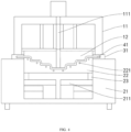
FIG. 4 is a structural schematic view of an embodiment of the present disclosure in an adsorbed state. -
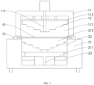
FIG. 5 is a structural schematic view of an embodiment of the present disclosure with an upper mold holder abutting against a material frame. -
FIG. 6 is a structural schematic view of a molded sheet according to an embodiment of the present disclosure. -
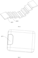
FIGS. 7 to 9 are structural schematic views of a housing. -
FIG. 10 is a structural schematic view of an embodiment of the present disclosure with an insert placed on a concave mold. - Reference numerals: 11-upper mold holder; 111-first airflow channel; 112-upper air cavity; 113-receiving plate;
- 12-convex mold;
- 21-lower mold holder; 211-second airflow channel; 212-lower air cavity;
- 22-concave mold; 221-waterway;
- 23-lifting platform;
- 31-material frame;
- 41-sheet; 411-glossy surface; 412-matte surface;
- 51-insert;
- 61-housing; 611-tie rod holder position; 612-placement slot.
- In order to make the purpose, technical solutions and advantages of the embodiments of the present disclosure clearer, the technical solutions in the embodiments of the present disclosure will be described clearly and completely below in conjunction with the accompanying drawings in the embodiments of the present disclosure, and it is clear that the embodiments described are a part of the embodiments of the present disclosure, and not all of them. Based on the embodiments in the present disclosure, all other embodiments obtained by those skilled in the art without making creative labor fall within the scope of the present disclosure. Accordingly, the following detailed description of the embodiments of the present disclosure provided in the accompanying drawings is not intended to limit the scope of the present disclosure claimed for protection, but merely to indicate selected embodiments of the present disclosure. Based on the embodiments in the present disclosure, all other embodiments obtained without creative labor by those skilled in the art fall within the scope of the present disclosure.
- In combination with
FIGS. 4 to 6 , the present embodiments provide a negative mold for molding a luggage, including an upper mold assembly, a lower mold assembly, and amaterial frame 31. The upper mold assembly includes anupper mold holder 11 and aconvex mold 12 adapted and connected to theupper mold holder 11, theupper mold holder 11 is arranged with afirst airflow channel 111 passing through theconvex mold 12, and theconvex mold 12 is capable of being driven by a drive member configured on theupper mold holder 11. The lower mold assembly includes alower mold holder 21, aconcave mold 22, and alifting platform 23 for driving theconcave mold 22; thematerial frame 31 is arranged on thelower mold holder 21 to clamp asheet 41 such that thesheet 41 is suspended above thelower mold holder 21; theconvex mold 12 and theconcave mold 22 are configured to switch between an adsorbed state and a mold detaching state; when in the adsorbed state, theupper mold holder 11 abuts against thematerial frame 31 to define anupper air cavity 112 above thesheet 41, theupper air cavity 112 being in communication with thefirst airflow channel 111, in which case air is blown downward through thefirst airflow channel 111 to stretch thesheet 41, while theconvex mold 12 and theconcave mold 22 move in the direction close to thesheet 41 to define a molding space, such that the stretchedsheet 41 fits theconcave mold 22 under a gas pressure of thefirst airflow channel 111, and is evenly distributed along the molding space under a pressure of theconvex mold 12; when in the mold detaching state, each of theconvex mold 12 and theconcave mold 22 moves toward a position away from thematerial frame 31 to detach the moldedsheet 41. - It should be noted that, in the embodiments, by arranging the
convex mold 12 on theupper mold holder 11, theconvex mold 12 is configured to cooperate with theconcave mold 22 to define the molding space for thesheet 41 to be molded. During the molding state, a side of thesheet 41 is attached to theconcave mold 22 and the other side is pressed by theconvex mold 12, such that it is evenly distributed in the molding space, which makes the thickness of the luggage uniform, guarantees the strength of the luggage, reduces decorations such as corner guards, reduces the cost, and improve the market competition rate. - Specifically, the
concave mold 22 includes a molding surface extending downward, and a pressing surface on theconvex mold 12 is set shape-similarly to the molding surface. The molding space is defined between the molding surface and the pressing surface in the adsorbed state. In some embodiments, the molding surface includes a grainy part and/or a glossy part; for example, a flat part of the molding surface is set to be grainy and a raised or depressed part is set to be glossy for forming amatte surface 412 and ashiny surface 411; or conversely, the raised or depressed part is set to be grainy and the flat part is set to be glossy, without specific limitation, so as to achieve partial graininess or shininess. In addition, most of the existing luggage blister molds are positive molds; when a grain is to be formed, it is necessary to set the grain on the sheet, and the grain will be deformed to different degrees when the sheet is stretched, and it is impossible to form a partial glossy surface or matte surface. In the embodiments, by setting the grain on the molding surface of theconcave mold 22, it may be ensured that the grain will not be deformed by the stretching of thesheet 41 and the grain will be clear and beautiful. - Based on the above embodiments, in some embodiments of the present disclosure, the
lower mold holder 21 is arranged with asecond airflow channel 211. When in the adsorbed state, alower air cavity 212 in communication with thesecond airflow channel 211 is defined between theconcave mold 22 and thelifting platform 23, in which case air is blown downward through thesecond airflow channel 211; when in the mold detaching state, air is blown upward through thesecond airflow channel 211. Both sides of theconcave mold 22 and thelower mold holder 21 are fitted and limited in position to ensure that theconcave mold 22 will not be shifted in the process of moving. It should be noted that in the embodiments, thefirst airflow channel 111 is connected to an upper air valve, specifically, the upper air valve may be connected to an air inlet on theconvex mold 12 through a hose or spring tube; and thesecond airflow channel 211 is connected to a lower air valve. The control principle about the air valve is prior art, and it will not be repeated herein. Thesecond airflow channel 211 assists in mold detaching or adsorption such that thesheet 41 may be evenly stressed and better fit to theconcave mold 22 during the molding process. - In some embodiments, the drive member may be a cylinder, and the
convex mold 12 is fixedly connected to a receivingplate 113 on theupper mold holder 11; the receivingplate 113 is driven by the cylinder to drive theconvex mold 12 up or down, without specific limitation herein. In other embodiments, the drive member performs the driving function through other structures. In some embodiments, thefirst airflow channel 111 is arranged along the middle of theconvex mold 12, which may be composed of multiple small air holes to avoid the impact of too large holes on thesheet 41 molding. Since the luggage is generally large in size,several waterways 221 may be arranged on theconcave mold 22, and eachwaterway 221 is laid out near a right angle of theconcave mold 22, such that the moldedsheet 41 can be cooled quickly to speed up the production efficiency. - A negative-mold blister molding method for a luggage is further provided, applied to the negative mold as described above. The method includes the following operations.
- When absorbing:
- S1: fixing the
sheet 41 on thematerial frame 31 and suspending thesheet 41 above thelower mold holder 21, and moving thematerial frame 31 to thelower mold holder 21 after baking of thesheet 41 is completed. - S2: heating the
sheet 41 and driving theupper mold holder 11 to abut against thematerial frame 31 to define theupper air cavity 112 above theupper mold holder 11 and thesheet 41. - S3: blowing air downward through the
first airflow channel 111 to stretch thesheet 41 into a bubble shape. - S4: continuing to blow air through the
first airflow channel 111, driving, by thelifting platform 23, theconcave mold 22 to move up, while sucking air through thesecond airflow channel 211 disposed in thelower mold holder 21, and pressurizing thesheet 41 on both sides to ensure a balanced force. - S5: lowering the
convex mold 12 to define the molding space with theconcave mold 22, and fitting thesheet 41 to theconcave mold 22 and molding thesheet 41 with the assistance of theconvex mold 12; - When the mold is being detached:
- S6: driving, by the
upper mold holder 11, theconvex mold 12 to rise simultaneously. - S7: lowering the
concave mold 22 and blowing air upward through thesecond airflow channel 211 to release the formedsheet 41 from theconcave mold 22. - It should be mentioned that during the adsorption, the air in the
first airflow channel 111 diffuses outwardly and downwardly from the middle of theconvex mold 12 to further guarantee the uniform force on thesheet 41. - In some embodiments, an
insert 51 may be placed on theconcave mold 22 before adsorption, such that theinsert 51 is integrally molded with thesheet 41 in the molding space, thereby reducing assembly. Theinsert 51 may be a tie rod holder. Combined withFIG. 7 , when molding an upper housing of the luggage, the tie rod holder may not be placed, and when molding a lower housing of the luggage, the tie rod holder may be placed at a tierod holder position 611, such that theinsert 51 and the lower housing are integrally molded, thereby realizing that the upper housing and the lower housing share the same mold. In addition, the tie rod holder and the lower housing are integrally molded, which can avoid the tie rod holder from exceeding the surface of thelower housing 61 and improve the surface quality. Theinsert 51 may also be a decorative ring, decorative strip, etc. Combined withFIGS. 8 and 9 , in the existinghousing 61 molding, when additional decorative parts are needed on thehousing 61, aplacement slot 612 is required to be machined on thehousing 61 by later machining. While in the embodiments, combined withFIG. 10 , the required decorative parts are only required to be placed on the molding surface of theconcave mold 22 to be integrally molded with thesheet 41, thereby strengthening thehousing 61 and beautifying thehousing 61. In addition, the shape and position of theinsert 51 are not fixed, allowing for a wider variety of appearance molding and improved versatility of the mold. In other embodiments, a metal foil may be placed on theconcave mold 22 to achieve a hot stamping effect. A foil with a pattern may be placed on theconcave mold 22 to achieve precise positioning of the pattern to be adsorbed onto the housing surface. In the existing housing blister molding, the pattern is printed on the surface of the sheet, and when the sheet is stretched and deformed, the printed pattern is deformed significantly. In the embodiments, the film pattern may be placed directly on the molding surface of the concave mold, and the film pattern is not stretched by adsorption, thereby ensuring that the pattern will not produce stretching deformation. - Another negative-mold blister molding method for a luggage is provided, including the following operations.
- When absorbing:
- S1: placing the
insert 51 on theconcave mold 22. - S2: fixing the
sheet 41 on thematerial frame 31 and suspending thesheet 41 above thelower mold holder 21, and moving thematerial frame 31 to thelower mold holder 21 after baking of thesheet 41 is completed. - S3: driving the
upper mold holder 11 to abut against thematerial frame 31 to define theupper air cavity 112 above theupper mold holder 11 and thesheet 41. - S4: blowing air downward through the
first airflow channel 111 to stretch thesheet 41 into a bubble shape. - S5: continuing to blow air through the
first airflow channel 111, driving, by thelifting platform 23, theconcave mold 22 to move up, while sucking air through thesecond airflow channel 211 disposed in thelower mold holder 21, and pressurizing thesheet 41 on both sides to ensure a balanced force, such that theinsert 51 on theconcave mold 22 is molded integrally with thesheet 41. - When the mold is being detached:
S6: lowering theconcave mold 22 and blowing air upward through thesecond airflow channel 211 to release the formedsheet 41 from theconcave mold 22. - It should be noted that in the embodiments, the
convex mold 12 may be controlled not to descend, and theconvex mold 12 may be removed if necessary to facilitate the pick and place of theinsert 51, as well as to avoid interference with theconvex mold 12 when the thickness of theinsert 51 is too large. The present disclosure makes no limitation in this regard. - The above is only some embodiments of the present disclosure, and the scope of the present disclosure is not limited to the above embodiments, and all technical solutions belonging to the ideas of the present disclosure belong to the scope of the present disclosure.
Claims (10)
- A negative-mold blister mold for molding a luggage, characterized by comprising:an upper mold assembly, comprising an upper mold holder (11) and a convex mold (12) adapted and connected to the upper mold holder (11); wherein the upper mold holder (11) is arranged with a first airflow channel (111) passing through the convex mold (12), and the convex mold (12) is capable of being driven by a drive member;a lower mold assembly, comprising a lower mold holder (21), a concave mold (22), and a lifting platform (23) for driving the concave mold (22) to move; anda material frame (31), arranged on the lower mold holder (21) to clamp a sheet (41), such that the sheet (41) is suspended above the lower mold holder (21);wherein the convex mold (12) and the concave mold (22) are configured to switch between an adsorbed state and a mold detaching state;in the adsorbed state, the upper mold holder (11) abuts against the material frame (31) to define an upper air cavity (112) above the sheet (41), the upper air cavity (112) being in communication with the first airflow channel (111); air is blown downward through the first airflow channel (111) to stretch the sheet (41), while each of the convex mold (12) and the concave mold (22) moves in a direction close to the sheet (41) to define a molding space, such that the stretched sheet (41) fits the concave mold (22) under a gas pressure of the first airflow channel (111) and is evenly distributed along the molding space under a pressure of the convex mold (12);in the mold detaching state, each of the convex mold (12) and the concave mold (22) moves toward in another direction away from the material frame (31) to detach the molded sheet (41).
- The negative-mold blister mold according to claim 1, wherein the concave mold (22) comprises a molding surface extending downward, and a pressing surface on the convex mold (12) is set shape-similarly to the molding surface; the molding space is defined between the molding surface and the pressing surface in the adsorbed state.
- The negative-mold blister mold according to claim 2, wherein the molding surface comprises a grainy part and/or a glossy part.
- The negative-mold blister mold according to claim 1, wherein the lower mold holder (21) is arranged with a second airflow channel (211); in the adsorbed state, a lower air cavity (212) in communication with the second airflow channel (211) is defined between the concave mold (22) and the lifting platform (23), and air is blown downward through the second airflow channel (211); in the mold detaching state, air is blown upward through the second airflow channel (211).
- The negative-mold blister mold according to claim 1, wherein the first airflow channel (111) is arranged along a middle of the convex mold (12).
- The negative-mold blister mold according to claim 1, wherein a plurality of waterways (221) are arranged on the concave mold (22), and each waterway (221) is laid out near a right angle of the concave mold (22).
- A negative-mold blister molding method for a luggage, applied to the negative-mold blister mold according to claim 4 and comprising:when absorbing:S1: fixing the sheet (41) on the material frame (31), and moving the material frame (31) to the lower mold holder (21) after baking of the sheet (41) is completed;S2: driving the upper mold holder (11) to abut against the material frame (31);S3: blowing air downward through the first airflow channel (111) to stretch the sheet (41) into a bubble shape;S4: continuing to blow air through the first airflow channel (111), driving, by the lifting platform (23), the concave mold (22) to move up, and sucking air through the second airflow channel (211) disposed in the lower mold holder (21); andS5: lowering the convex mold (12) to define the molding space with the concave mold (22), and fitting the sheet (41) to the concave mold (22) and molding the sheet (41) with an assistance of the convex mold (12);when the mold is being detached:S6: driving, by the upper mold holder (11), the convex mold (12) to rise simultaneously; andS7: lowering the concave mold (22) and blowing air upward through the second airflow channel (211) to release the formed sheet (41) from the concave mold (22).
- The method according to claim 7, wherein when absorbing, the air in the first airflow channel (111) diffuses outwardly and downwardly from a middle of the convex mold (12).
- The method according to claim 7, wherein an insert (51) is placed on the concave mold (22) before the absorbing, such that the insert (51) is integrally molded with the sheet (41) in the molding space.
- A negative-mold blister molding method for a luggage, applied to the negative-mold blister mold according to claim 4 and comprising:when absorbing:S1: placing an insert (51) on the concave mold (22);S2: fixing the sheet (41) on the material frame (31), and moving the material frame (31) to the lower mold holder (21) after baking of the sheet (41) is completed;S3: driving the upper mold holder (11) to abut against the material frame (31);S4: blowing air downward through the first airflow channel (111) to stretch the sheet (41) into a bubble shape; andS5: continuing to blow air through the first airflow channel (111), driving, by the lifting platform (23), the concave mold (22) to move up, and sucking air through the second airflow channel (211) disposed in the lower mold holder (21), such that the insert (51) on the concave mold (22) is molded integrally with the sheet (41);when the mold is being detached:
S6: lowering the concave mold (22) and blowing air upward through the second airflow channel (211) to release the formed sheet (41) from the concave mold (22).
Applications Claiming Priority (1)
| Application Number | Priority Date | Filing Date | Title |
|---|---|---|---|
| CN202310731692.6A CN119141836A (en) | 2023-06-16 | 2023-06-16 | Female mold plastic suction mold for molding bags and application thereof |
Publications (3)
| Publication Number | Publication Date |
|---|---|
| EP4477385A1 true EP4477385A1 (en) | 2024-12-18 |
| EP4477385C0 EP4477385C0 (en) | 2026-01-21 |
| EP4477385B1 EP4477385B1 (en) | 2026-01-21 |
Family
ID=93561779
Family Applications (1)
| Application Number | Title | Priority Date | Filing Date |
|---|---|---|---|
| EP23186565.0A Active EP4477385B1 (en) | 2023-06-16 | 2023-07-20 | Negative mold for luggage molding and application thereof |
Country Status (4)
| Country | Link |
|---|---|
| EP (1) | EP4477385B1 (en) |
| JP (1) | JP2024180220A (en) |
| KR (1) | KR20240176748A (en) |
| CN (1) | CN119141836A (en) |
Citations (5)
| Publication number | Priority date | Publication date | Assignee | Title |
|---|---|---|---|---|
| DE3010507A1 (en) * | 1979-11-20 | 1981-05-21 | Kabushiki Kaisha Asano Kenkyusho, Nagoya, Aichi | METHOD AND DEVICE FOR DEFORMING A THERMOPLASTIC PLATE IN A DEEP HOLLOW BODY BY LOW PRESSURE AND HEAT WITH THE FLOW LINES OFF ON THE OUTSIDE |
| JPH02147317A (en) * | 1988-11-30 | 1990-06-06 | Ajinomoto Co Inc | Method and apparatus for molding plastic container |
| US20160297126A1 (en) * | 2015-04-10 | 2016-10-13 | Panasonic Intellectual Property Management Co., Ltd. | In-mold decoration molding method and in-mold decoration molding machine |
| EP3819104A1 (en) * | 2019-11-06 | 2021-05-12 | Vocier GmbH | Method for producing a component and container with at least one such component |
| CN218366097U (en) * | 2022-07-29 | 2023-01-24 | 滁州市预见旅游用品有限公司 | Injection mold and case shell forming mold |
Family Cites Families (4)
| Publication number | Priority date | Publication date | Assignee | Title |
|---|---|---|---|---|
| US5441675A (en) * | 1993-11-01 | 1995-08-15 | Davidson Textron, Inc. | Forming method and apparatus |
| JPH0976403A (en) * | 1995-09-18 | 1997-03-25 | Idemitsu Petrochem Co Ltd | Thermoforming sheet and thermoformed product |
| JP2003159743A (en) * | 2001-11-28 | 2003-06-03 | Toyo Seikan Kaisha Ltd | Manufacturing method of synthetic resin container |
| WO2023095778A1 (en) * | 2021-11-26 | 2023-06-01 | 株式会社漆原 | Method for manufacturing molded article with molding die produced by 3d printer and molded article |
-
2023
- 2023-06-16 CN CN202310731692.6A patent/CN119141836A/en active Pending
- 2023-07-20 EP EP23186565.0A patent/EP4477385B1/en active Active
- 2023-08-11 JP JP2023131717A patent/JP2024180220A/en active Pending
- 2023-08-16 KR KR1020230107262A patent/KR20240176748A/en not_active Ceased
Patent Citations (5)
| Publication number | Priority date | Publication date | Assignee | Title |
|---|---|---|---|---|
| DE3010507A1 (en) * | 1979-11-20 | 1981-05-21 | Kabushiki Kaisha Asano Kenkyusho, Nagoya, Aichi | METHOD AND DEVICE FOR DEFORMING A THERMOPLASTIC PLATE IN A DEEP HOLLOW BODY BY LOW PRESSURE AND HEAT WITH THE FLOW LINES OFF ON THE OUTSIDE |
| JPH02147317A (en) * | 1988-11-30 | 1990-06-06 | Ajinomoto Co Inc | Method and apparatus for molding plastic container |
| US20160297126A1 (en) * | 2015-04-10 | 2016-10-13 | Panasonic Intellectual Property Management Co., Ltd. | In-mold decoration molding method and in-mold decoration molding machine |
| EP3819104A1 (en) * | 2019-11-06 | 2021-05-12 | Vocier GmbH | Method for producing a component and container with at least one such component |
| CN218366097U (en) * | 2022-07-29 | 2023-01-24 | 滁州市预见旅游用品有限公司 | Injection mold and case shell forming mold |
Also Published As
| Publication number | Publication date |
|---|---|
| KR20240176748A (en) | 2024-12-24 |
| EP4477385C0 (en) | 2026-01-21 |
| JP2024180220A (en) | 2024-12-26 |
| US20240416573A1 (en) | 2024-12-19 |
| EP4477385B1 (en) | 2026-01-21 |
| CN119141836A (en) | 2024-12-17 |
Similar Documents
| Publication | Publication Date | Title |
|---|---|---|
| US9783928B2 (en) | Full-automatic manufacturing method of plant fiber molded product, and multifunctional machine for molding and trimming | |
| KR20160042878A (en) | Die set, thermal forming device, thermal forming method, and thermally formed product | |
| CA2156285A1 (en) | Molded Product Manufacturing Apparatus and Methods | |
| US12629882B2 (en) | Negative mold for luggage molding and application thereof | |
| US20240416573A1 (en) | Negative mold for luggage molding and application thereof | |
| HK40115189A (en) | Negative mold for luggage molding and application thereof | |
| KR20170034579A (en) | Press Type Thermal Transferring Apparatus of Curved Surface Glass | |
| JP2021126803A (en) | Thermoforming equipment and thermoforming method | |
| US20030003280A1 (en) | Method of manufacturing film insert molding | |
| JP3640032B2 (en) | Manufacturing method of carrier tape | |
| CN212764738U (en) | Box cover plastic uptake device | |
| CN220023507U (en) | Small square piezoelectric ceramic plate silver printing tool groove plate | |
| CN209259924U (en) | A kind of positive pressure bend glass molding die and its heating equipment | |
| CN218366020U (en) | A mould for making software robot | |
| CN217373435U (en) | Case female mold plastic suction mold | |
| CN114889022B (en) | A 3D printing-based soft robot mold and its manufacturing method | |
| CN206375817U (en) | A kind of mould of the side hot bending products of 3D tetra- | |
| CN211105564U (en) | Plastic uptake device of convenient drawing of patterns | |
| JPH07232499A (en) | Heat transfer device | |
| CN109968889B (en) | Alignment jig and out-of-mold decoration method using the same | |
| CN210233665U (en) | Cloth clamping diaphragm die | |
| JPS6331732A (en) | Thermoforming of vessel and the like | |
| CN213593613U (en) | Automatic demolding plastic suction mold | |
| JP3641973B2 (en) | MATCHED DIE MOLDING METHOD AND MATCHED DIE MOLDING DEVICE | |
| CN220808895U (en) | Heat transfer film cooling device |
Legal Events
| Date | Code | Title | Description |
|---|---|---|---|
| PUAI | Public reference made under article 153(3) epc to a published international application that has entered the european phase |
Free format text: ORIGINAL CODE: 0009012 |
|
| STAA | Information on the status of an ep patent application or granted ep patent |
Free format text: STATUS: REQUEST FOR EXAMINATION WAS MADE |
|
| 17P | Request for examination filed |
Effective date: 20230807 |
|
| AK | Designated contracting states |
Kind code of ref document: A1 Designated state(s): AL AT BE BG CH CY CZ DE DK EE ES FI FR GB GR HR HU IE IS IT LI LT LU LV MC ME MK MT NL NO PL PT RO RS SE SI SK SM TR |
|
| REG | Reference to a national code |
Ref country code: HK Ref legal event code: DE Ref document number: 40115189 Country of ref document: HK |
|
| GRAP | Despatch of communication of intention to grant a patent |
Free format text: ORIGINAL CODE: EPIDOSNIGR1 |
|
| STAA | Information on the status of an ep patent application or granted ep patent |
Free format text: STATUS: GRANT OF PATENT IS INTENDED |
|
| RIC1 | Information provided on ipc code assigned before grant |
Ipc: B29C 51/06 20060101AFI20250812BHEP Ipc: B29C 51/08 20060101ALN20250812BHEP Ipc: B29C 51/10 20060101ALN20250812BHEP Ipc: B29C 51/12 20060101ALN20250812BHEP Ipc: B29C 51/38 20060101ALN20250812BHEP Ipc: B29C 51/42 20060101ALN20250812BHEP Ipc: B29C 51/44 20060101ALN20250812BHEP Ipc: B29C 43/02 20060101ALN20250812BHEP Ipc: B29C 59/02 20060101ALN20250812BHEP Ipc: B29L 31/00 20060101ALN20250812BHEP Ipc: B65D 43/16 20060101ALN20250812BHEP |
|
| INTG | Intention to grant announced |
Effective date: 20250822 |
|
| GRAS | Grant fee paid |
Free format text: ORIGINAL CODE: EPIDOSNIGR3 |
|
| GRAA | (expected) grant |
Free format text: ORIGINAL CODE: 0009210 |
|
| STAA | Information on the status of an ep patent application or granted ep patent |
Free format text: STATUS: THE PATENT HAS BEEN GRANTED |
|
| AK | Designated contracting states |
Kind code of ref document: B1 Designated state(s): AL AT BE BG CH CY CZ DE DK EE ES FI FR GB GR HR HU IE IS IT LI LT LU LV MC ME MK MT NL NO PL PT RO RS SE SI SK SM TR |
|
| REG | Reference to a national code |
Ref country code: CH Ref legal event code: F10 Free format text: ST27 STATUS EVENT CODE: U-0-0-F10-F00 (AS PROVIDED BY THE NATIONAL OFFICE) Effective date: 20260121 |
|
| REG | Reference to a national code |
Ref country code: DE Ref legal event code: R096 Ref document number: 602023010934 Country of ref document: DE |
|
| REG | Reference to a national code |
Ref country code: IE Ref legal event code: FG4D |
|
| U01 | Request for unitary effect filed |
Effective date: 20260218 |
|
| U07 | Unitary effect registered |
Designated state(s): AT BE BG DE DK EE FI FR IT LT LU LV MT NL PT RO SE SI Effective date: 20260223 |