EP4477348A1 - Schweissstruktur, schweissvorrichtung und schweissverfahren - Google Patents
Schweissstruktur, schweissvorrichtung und schweissverfahren Download PDFInfo
- Publication number
- EP4477348A1 EP4477348A1 EP22933045.1A EP22933045A EP4477348A1 EP 4477348 A1 EP4477348 A1 EP 4477348A1 EP 22933045 A EP22933045 A EP 22933045A EP 4477348 A1 EP4477348 A1 EP 4477348A1
- Authority
- EP
- European Patent Office
- Prior art keywords
- weld
- adjustment
- characteristic value
- deformation
- cover plate
- Prior art date
- Legal status (The legal status is an assumption and is not a legal conclusion. Google has not performed a legal analysis and makes no representation as to the accuracy of the status listed.)
- Pending
Links
Images

Classifications
-
- B—PERFORMING OPERATIONS; TRANSPORTING
- B23—MACHINE TOOLS; METAL-WORKING NOT OTHERWISE PROVIDED FOR
- B23K—SOLDERING OR UNSOLDERING; WELDING; CLADDING OR PLATING BY SOLDERING OR WELDING; CUTTING BY APPLYING HEAT LOCALLY, e.g. FLAME CUTTING; WORKING BY LASER BEAM
- B23K37/00—Auxiliary devices or processes, not specially adapted for a procedure covered by only one of the other main groups of this subclass
- B23K37/04—Auxiliary devices or processes, not specially adapted for a procedure covered by only one of the other main groups of this subclass for holding or positioning work
- B23K37/0408—Auxiliary devices or processes, not specially adapted for a procedure covered by only one of the other main groups of this subclass for holding or positioning work for planar work
-
- B—PERFORMING OPERATIONS; TRANSPORTING
- B23—MACHINE TOOLS; METAL-WORKING NOT OTHERWISE PROVIDED FOR
- B23K—SOLDERING OR UNSOLDERING; WELDING; CLADDING OR PLATING BY SOLDERING OR WELDING; CUTTING BY APPLYING HEAT LOCALLY, e.g. FLAME CUTTING; WORKING BY LASER BEAM
- B23K26/00—Working by laser beam, e.g. welding, cutting or boring
- B23K26/08—Devices involving relative movement between laser beam and workpiece
- B23K26/0869—Devices involving movement of the laser head in at least one axial direction
- B23K26/0876—Devices involving movement of the laser head in at least one axial direction in at least two axial directions
- B23K26/0884—Devices involving movement of the laser head in at least one axial direction in at least two axial directions in at least in three axial directions, e.g. manipulators, robots
-
- B—PERFORMING OPERATIONS; TRANSPORTING
- B23—MACHINE TOOLS; METAL-WORKING NOT OTHERWISE PROVIDED FOR
- B23K—SOLDERING OR UNSOLDERING; WELDING; CLADDING OR PLATING BY SOLDERING OR WELDING; CUTTING BY APPLYING HEAT LOCALLY, e.g. FLAME CUTTING; WORKING BY LASER BEAM
- B23K26/00—Working by laser beam, e.g. welding, cutting or boring
- B23K26/346—Working by laser beam, e.g. welding, cutting or boring in combination with welding or cutting covered by groups B23K5/00 - B23K25/00, e.g. in combination with resistance welding
- B23K26/348—Working by laser beam, e.g. welding, cutting or boring in combination with welding or cutting covered by groups B23K5/00 - B23K25/00, e.g. in combination with resistance welding in combination with arc heating, e.g. TIG [tungsten inert gas], MIG [metal inert gas] or plasma welding
-
- B—PERFORMING OPERATIONS; TRANSPORTING
- B23—MACHINE TOOLS; METAL-WORKING NOT OTHERWISE PROVIDED FOR
- B23K—SOLDERING OR UNSOLDERING; WELDING; CLADDING OR PLATING BY SOLDERING OR WELDING; CUTTING BY APPLYING HEAT LOCALLY, e.g. FLAME CUTTING; WORKING BY LASER BEAM
- B23K26/00—Working by laser beam, e.g. welding, cutting or boring
- B23K26/70—Auxiliary operations or equipment
- B23K26/702—Auxiliary equipment
-
- B—PERFORMING OPERATIONS; TRANSPORTING
- B23—MACHINE TOOLS; METAL-WORKING NOT OTHERWISE PROVIDED FOR
- B23K—SOLDERING OR UNSOLDERING; WELDING; CLADDING OR PLATING BY SOLDERING OR WELDING; CUTTING BY APPLYING HEAT LOCALLY, e.g. FLAME CUTTING; WORKING BY LASER BEAM
- B23K31/00—Processes relevant to this subclass, specially adapted for particular articles or purposes, but not covered by only one of the preceding main groups
- B23K31/003—Processes relevant to this subclass, specially adapted for particular articles or purposes, but not covered by only one of the preceding main groups relating to controlling of welding distortion
-
- B—PERFORMING OPERATIONS; TRANSPORTING
- B23—MACHINE TOOLS; METAL-WORKING NOT OTHERWISE PROVIDED FOR
- B23K—SOLDERING OR UNSOLDERING; WELDING; CLADDING OR PLATING BY SOLDERING OR WELDING; CUTTING BY APPLYING HEAT LOCALLY, e.g. FLAME CUTTING; WORKING BY LASER BEAM
- B23K37/00—Auxiliary devices or processes, not specially adapted for a procedure covered by only one of the other main groups of this subclass
- B23K37/04—Auxiliary devices or processes, not specially adapted for a procedure covered by only one of the other main groups of this subclass for holding or positioning work
- B23K37/0426—Fixtures for other work
- B23K37/0452—Orientable fixtures
-
- B—PERFORMING OPERATIONS; TRANSPORTING
- B23—MACHINE TOOLS; METAL-WORKING NOT OTHERWISE PROVIDED FOR
- B23K—SOLDERING OR UNSOLDERING; WELDING; CLADDING OR PLATING BY SOLDERING OR WELDING; CUTTING BY APPLYING HEAT LOCALLY, e.g. FLAME CUTTING; WORKING BY LASER BEAM
- B23K37/00—Auxiliary devices or processes, not specially adapted for a procedure covered by only one of the other main groups of this subclass
- B23K37/04—Auxiliary devices or processes, not specially adapted for a procedure covered by only one of the other main groups of this subclass for holding or positioning work
- B23K37/0461—Welding tables
-
- B—PERFORMING OPERATIONS; TRANSPORTING
- B23—MACHINE TOOLS; METAL-WORKING NOT OTHERWISE PROVIDED FOR
- B23K—SOLDERING OR UNSOLDERING; WELDING; CLADDING OR PLATING BY SOLDERING OR WELDING; CUTTING BY APPLYING HEAT LOCALLY, e.g. FLAME CUTTING; WORKING BY LASER BEAM
- B23K2101/00—Articles made by soldering, welding or cutting
- B23K2101/18—Sheet panels
-
- B—PERFORMING OPERATIONS; TRANSPORTING
- B61—RAILWAYS
- B61F—RAIL VEHICLE SUSPENSIONS, e.g. UNDERFRAMES, BOGIES OR ARRANGEMENTS OF WHEEL AXLES; RAIL VEHICLES FOR USE ON TRACKS OF DIFFERENT WIDTH; PREVENTING DERAILING OF RAIL VEHICLES; WHEEL GUARDS, OBSTRUCTION REMOVERS OR THE LIKE FOR RAIL VEHICLES
- B61F1/00—Underframes
- B61F1/08—Details
Definitions
- the present application relates to the field of welding, and in particular, to a weld structure, a weld device and a weld method.
- An underframe bolster beam, a traction beam and a bogie frame side beam at the end of a vehicle body are the most important load-bearing components of rail vehicles. Since the rail vehicles are subjected to severe alternating load conditions during operation, multi-layer and multi-pass melt active gas (MAG) arc welding process is adopted to ensure good load-bearing service capacity of the rail vehicles. A large heat input of arc welding results in serious welding deformation and a lot of manpower and material resources are required after welding for adjustment and correction, resulting in strength loss and performance degradation. An added back pad seriously reduces fatigue resistance of a box-shaped structure.
- MAG melt active gas
- the present application provides a weld structure which solves defects that a traditional box-shaped structure needs to be adjusted and corrected, resulting in strength loss and performance degradation.
- a stable and enclosed box-shaped structure is formed by inserting and interlocking the upper and lower cover plates, and the rigidity of the box-shaped structure is increased.
- the present application further provides a weld device for a weld structure, which solves defects of strength loss and performance degradation due to manual adjustment and correction, inability to effectively suppress welding deformation, large workload of repeated check, inability to accurately and dynamically adjust the weld structure based on the evolution trend of deformation and change amount of a weld structure, and poor anti-deformation effect.
- a weld device for a weld structure which solves defects of strength loss and performance degradation due to manual adjustment and correction, inability to effectively suppress welding deformation, large workload of repeated check, inability to accurately and dynamically adjust the weld structure based on the evolution trend of deformation and change amount of a weld structure, and poor anti-deformation effect.
- the present application further provides a weld method of a weld device, which solves defects of inability to avoid adjustment and correction to a weld structure, inability to effectively suppress welding deformation, large workload of repeated check, inability to accurately and dynamically adjust the weld structure based on the evolution trend of deformation and change amount of a weld structure, and poor anti-deformation effect.
- a magnitude of the multi-point flexible force at the support surface zero-gap rapid and precise assembly, multi-point flexible constraint and multi-energy field coordinated high-performance welding are provided, and engineering goals of fine control of welding deformation, effective suppression of welding defects and substantial improvement of weld microstructure performance are simultaneously achieved.
- An embodiment of the present application provides a weld structure, including:
- a surface of the first cover plate is provided with a plurality of first slots and a plurality of second slots
- the present embodiment provides the first cover plate, and the first cover plate is insertedly matched with the web plates and the rib plates by providing the first slots and the second slots.
- the grooves are provided at the sides of each of the first slots and the second slots facing the second cover plate, which facilitates the zero-gap rapid and precise assembly of the inserted interlocking structure.
- the back forming of the weld is further improved and the penetration of a weld root is improved, which not only meets the assembly requirements but also improves the assembly efficiency.
- a surface of the second cover plate is provided with a plurality of third slots and a plurality of fourth slots
- the present embodiment provides the second cover plate, and the second cover plate is insertedly matched with the web plates and the rib plates by providing the third slots and the fourth slots.
- the grooves are provided at sides of each of the third slots and the fourth slots facing the second cover plate, which facilitates the zero-gap rapid and precise assembly of the inserted interlocking structure.
- the back forming of the weld is further improved and the penetration of a weld root is improved, which not only meets the assembly requirements but also improves the assembly efficiency.
- the first cover plate, the second cover plate, the web plates and the rib plates are all made of high-strength weather-resistant steel.
- the present embodiment provides a material of the weld structure. With the increase of the running speed of the vehicle and urban rail trains, a requirement for lightweight trains is more urgent. Common low-alloy steel is replaced with the high-strength weather-resistant steel to achieve a lightweight design, which utilizes engineering characteristics of the high-strength weather-resistant steel, such as high strength, good plasticity, excellent fatigue performance and good economy.
- An embodiment of the present application further provides a weld device for a weld structure, including: a support portion, a weld portion and an adjustment portion,
- the support portion includes a support table and a drive unit
- the present embodiment provides the support portion.
- the weld structure is supported by providing the support table, and the support table is flappable through the drive unit and requirements of welding are satisfied from different angles.
- the weld portion is a laser-arc hybrid welding mechanism connected with the support portion.
- the present embodiment provides the weld portion.
- laser-arc hybrid welding By combining laser-arc hybrid welding with the support portion and the adjustment portion, an entire manufacturing process from development of a product structure, research and development on the weld device to control of a welding process is innovated systematically, barriers of difficult assembly, low efficiency and poor stability of a closed box-shaped structure using traditional laser-arc hybrid welding are effectively broken through, engineering problems that a laser-arc hybrid welding gun has a large size and a traditional assembly mode has many spatial interferences are solved, and bottlenecks that welding porosity is difficultly to avoid and a back has poor forming during laser-arc hybrid welding of medium and thick plates are broken through.
- the adjustment portion includes: a plurality of magnetic units and a plurality of sensor units,
- the present embodiment provides the adjustment portion, and the magnetic units and the sensor units are arranged at a surface of the support table, that is, the support surface, to position the closed box-shaped weld structure made of the high-strength weather-resistant steel and obtain corresponding parameters during the welding process, and engineering goals of fine control of weld deformation, effective suppression of weld defects and significant improvement of weld structure performance are obtained.
- An embodiment of the present application further provides a weld method based on a weld device, including:
- obtaining the first weld characteristic value of the weld structure during the welding process includes:
- the present embodiment provides obtaining the first weld characteristic value of the weld structure during the welding process, and corresponding first weld characteristic value is generated by obtaining the deformation characteristic value of the weld structure during the welding process.
- generating the first adjustment strategy for regulating the deformation amount of the weld surface of the weld structure based on the first weld characteristic value includes:
- the present embodiment provides an implementation for generating the first adjustment strategy for regulating the deformation amount of the weld surface of the weld structure, anti-deformation adjustment of the weld structure during the welding process is implemented by adjusting a magnitude of an adsorption force of the magnetic unit corresponding to the deformation area based on the adsorption force parameter.
- the friction force parameter needs to be monitored to avoid the problem that the weld structure moves during the welding process due to insufficient adsorption force.
- generating the first adjustment strategy for the preset adjustment area based on the first adjustment characteristic value and the second adjustment characteristic value includes:
- the present embodiment provides an implementation for generating the first adjustment strategy based on the preset adjustment area.
- the digital twin model By constructing the digital twin model, the anti-deformation amount of the weld structure is calculated, and the adsorption force parameter between the support table and the weld structure are verified, to avoid the problem that the weld structure moves on the support table due to insufficient adsorption force of the magnetic unit.
- performing anti-deformation adjustment in real time at the weld structure during the welding process based on the first adjustment strategy includes:
- the present embodiment provides performing anti-deformation adjustment in real time at the weld structure.
- By monitoring the magnetic field within the preset range around the deformation area of the weld structure a problem of excessive disturbance to the magnetic field in the surrounding area caused by adjusting the magnetic unit corresponding to the deformation area is avoided, the weld quality is guaranteed, and dynamic regulation of welding deformation in the hybrid welding process is satisfied to ensure engineering requirements of accurate weld position and enhanced weld stability.
- the method further includes:
- the present embodiment provides stirring the weld pool of the weld structure using the magnetic field.
- a plasma is effectively suppressed, a droplet flight speed and a weld pool flow speed of the laser-arc hybrid welding are increased, the thermal transmission and energy efficiency of the laser and arc are improved, and more stable droplet transition and better arc directivity are obtained.
- a stirring effect of the magnetic field is formed inside the weld pool to further refine the weld grain structure and enhance the gas escape capability.
- the mechanical properties and fatigue strength of a hybrid weld joint under the superposition of the magnetic field are improved by at least 5% compared with a traditional hybrid weld joint.
- the box-shaped structure is inserted and interlocked by using the upper and lower cover plates, and a stable closed box-shaped structure is formed to increase the rigidity of the structure.
- orientation or positional relations specified by terms such as “central”, “longitudinal”, “traverse”, “upper”, “lower”, “front”, “back”, “left”, “right”, “vertical”, “horizontal”, “top”, “bottom”, “inner”, “outer” and the like are based on the orientation or positional relations shown in the drawings, which is merely for convenience of description of the present application and to simplify description, but does not indicate or imply that the stated devices or components must have a particular orientation and be constructed and operated in a particular orientation, and thus it is not to be construed as limiting the present application.
- the terms “first”, “second”, “third” and the like are only used for descriptive purposes and should not be construed as indicating or implying a relative importance.
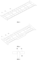
- the present embodiment provides a weld structure, including: a first cover plate 10, a second cover plate 20, a plurality of web plates 30 and a plurality of rib plates 40.
- the first cover plate 10 and the second cover plate 20 are arranged at intervals.
- the web plates 30 are arranged at intervals along a first direction and are insertedly matched with the first cover plate 10 and the second cover plate 20, respectively and the rib plates 40 are arranged at intervals along a second direction and are insertedly matched with the first cover plate 10 and the second cover plate 20, respectively, the first direction and the second direction are perpendicular to each other and the web plates 30 and the rib plates 40 are insertedly matched with each other.
- the present application provides a weld structure which solves defects that a traditional box-shaped structure needs to be adjusted and corrected, resulting in strength loss and performance degradation.
- a stable and enclosed box-shaped structure is formed by inserting and interlocking the upper and lower cover plates, and the rigidity of the box-shaped structure is increased.
- a surface of the first cover plate 10 is provided with a plurality of first slots 11 and a plurality of second slots 12.
- the first slots 11 are arranged at intervals along the first direction, and each of the first slots 11 is insertedly matched with each of the web plates 30 in a one-to-one correspondence.
- the second slots 12 are arranged at intervals along the second direction, and each of the second slots 12 is insertedly matched with each of the rib plates 40 in a one-to-one correspondence.
- Grooves 50 are provided at sides of each of the first slots 11 and the second slots 12 facing the second cover plate 20.
- the present embodiment provides the first cover plate 10, and the first cover plate 10 is insertedly matched with the web plates 30 and the rib plates 40 by providing the first slots 11 and the second slots 12.
- the grooves 50 are provided at the sides of each of the first slot 11 and the second slot 12 facing the second cover plate 20, which facilitates the zero-gap rapid and precise assembly of the inserted interlocking structure.
- the back forming of the weld is further improved and the penetration of a weld root is improved, which not only meets the assembly requirements but also improves the assembly efficiency.
- the groove 50 is a single V-shaped groove provided at the side of the first cover plate 10 facing the second cover plate 20.
- a surface of the second cover plate 20 is provided with a plurality of third slots 21 and a plurality of fourth slots 22.
- the third slots 21 are arranged at intervals along the first direction, and each of the third slots 21 is insertedly matched with each of the web plates 30 in a one-to-one correspondence.
- the fourth slots 22 are arranged at intervals along the second direction, and each of the fourth slots 22 is insertedly matched with each of the rib plate 40 in a one-to-one correspondence.
- Grooves 50 are provided at sides of each of the third slots 21 and the fourth slots 22 facing the first cover plate 10.
- the present embodiment provides the second cover plate 20, and the second cover plate 20 is insertedly matched with the web plates 30 and the rib plates 40 by providing the third slots 21 and the fourth slots 22.
- the grooves 50 are provided at the sides of each of the third slots 21 and the fourth slots 22 facing the second cover plate 10, which facilitates the zero-gap rapid and precise assembly of the inserted interlocking structure.
- the back forming of the weld is further improved and the penetration of a weld root is improved, which not only meets the assembly requirements but also improves the assembly efficiency.
- the groove 50 is a single V-shaped groove provided at the side of the first cover plate 10 facing the second cover plate 20.
- the first cover plate 10, the second cover plate 20, the web plates 30 and the rib plates 40 are all made of high-strength weather-resistant steel.
- the present embodiment provides a material of the weld structure. With the increase of the running speed of the vehicle and urban rail trains, a requirement for lightweight trains is more urgent. Common low-alloy steel is replaced with the high-strength weather-resistant steel for providing lightweight design, which utilizes engineering characteristics of the high-strength weather-resistant steel, such as high strength, good plasticity, excellent fatigue performance, and good economy.
- the weld structure is made of high-strength weather-resistant steel, and the thickness is thinned from the original 8 to 12 mm to 5 to 8 mm, which is at least 20% lighter than a traditional closed box-shaped structure.
- the weld structure is applied to a chassis of a rail vehicle.
- the weld structure is a bolster beam of the rail vehicle.
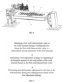
- the present solution provides a weld device for a weld structure, including a support portion, a weld portion 100 and an adjustment portion.
- the support portion is formed with a support surface for supporting the weld structure;
- the weld portion 100 is connected to the support portion for welding the weld structure;
- the adjustment portion is connected to the support portion and abuts against a weld surface of the weld structure.
- the adjustment portion regulates a flatness of the weld structure by adjusting a magnitude of a force acting on the weld surface of the weld structure
- the present application further provides the weld device for the weld structure, which solves defects of strength loss and performance degradation due to manual adjustment and correction, inability to effectively suppress welding deformation, large workload of repeated check, inability to accurately and dynamically adjust the weld structure based on the evolution trend of deformation and change amount of a weld structure, and poor anti-deformation effect.
- welding deformation is finely controlled, welding defects are precisely suppressed, microstructure performance is effectively improved, the manufacturing accuracy is increased, the manufacturing cost is reduced, and the production efficiency is greatly improved.
- the support portion includes a support table 60 and a drive unit 70.
- a surface of the support table 60 forms a support surface and the drive unit 70 is connected to the support table 60 to adjust the rotation angle of the support table 60.
- the present embodiment provides the support portion.
- the weld structure is supported by providing the support table 60, and the support table 60 is flappable through the drive unit and requirements of welding are satisfied from different angles.
- a traditional bolster beam is welded using a single welding mechanism, that is, a single welding gun.
- a single welding mechanism that is, a single welding gun.
- problems such as manual turning, repeated positioning and clamping, which makes it difficult to clamp and form the bolster in one step. Therefore, the processing accuracy of the bolster beam is affected and the labor intensity is increased.
- the bolster beam is supported singly in the related art and the post-welding manufacturing accuracy of the box-shaped bolster structure still does not meet the adjustment-free standard under a single welding deformation suppression measure.
- the present application does not limit the specific structure of the drive unit 70.
- the drive unit 70 includes a motor, a bearing, a support mechanism, a transmission mechanism, etc.
- the specific structure of the drive unit 70 are not elaborated too much in the present application. In practical applications, those skilled in the art can refer to the arrangement in related fields as required.
- the weld portion 100 is a laser-arc hybrid welding mechanism connected with the support portion.
- the present embodiment provides the weld portion 100.
- laser-arc hybrid welding By combining laser-arc hybrid welding with the support portion and the adjustment portion, an entire manufacturing process from development of a product structure, research and development on the weld device to control of a welding process is innovated systematically, barriers of difficult assembly, low efficiency and poor stability of a closed box-shaped structure using traditional laser-arc hybrid welding are effectively broken through, engineering problems that a laser-arc hybrid welding gun has a large size and a traditional assembly mode has many spatial interferences are solved, and bottlenecks that welding porosity is difficult to avoid and a back has poor forming during laser-arc hybrid welding of medium and thick plates are broken through.
- laser-arc hybrid welding cooperates with the groove 50 of the corresponding weld seam at the back of the weld structure, which greatly facilitates the escape of gas inside the weld pool of the laser-arc hybrid welding from the back of the weld pool, and effectively suppresses the welding porosity defects of laser-arc hybrid welding of a medium and thick plate.
- the laser-arc hybrid welding mechanism completes the welding using a process of one-time welding and forming of a weld surface during the welding process of the weld structure.
- the adjustment portion includes a plurality of magnetic units 80 and a plurality of sensor units 90.
- the magnetic units 80 are arranged at the support table 60 to position the weld structure through magnetic adsorption; and the sensor units 90 are arranged at the support table 60 to feed back welding parameters used in the welding process of the weld structure to the weld portion 100.
- the present embodiment provides the adjustment portion, and the magnetic units 80 and the sensor units 90 are arranged at a surface of the support table 60, that is, the support surface, to position the closed box-shaped weld structure made of the high-strength weather-resistant steel and obtain corresponding parameters during the welding process, and engineering goals of fine control of weld deformation, effective suppression of weld defects and significant improvement of weld structure performance are obtained.
- the enclosed box-shaped structure of high-strength weather-resistant steel is complex, with a large number of weld seams, a small welding spacing (the minimum spacing is 5 mm), and strict assembly requirements, and the assembly error must be controlled within the range of 0 to 0.5 mm and assembly is difficult, and the traditional assembly mode is difficult to meet the special assembly requirements of laser-arc hybrid welding.
- laser-arc hybrid welding has engineering characteristics such as small welding deformation, high manufacturing precision, strong penetration capability, good weld quality, fast welding speed, and high operating efficiency, it still has disadvantages that the laser-arc hybrid welding gun has large volume, a welding space is easily interfered, a traditional positioning and clamping device occupies a large amount of physical space when the laser-arc hybrid welding is used for the enclosed box-shaped structure and it is impossible to obtain full-automatic spatial welding of the enclosed box-shaped structure during laser-arc hybrid welding.
- the enclosed box-shaped weld structure made of high-strength weather-resistant steel is adsorbed by arranging magnetic units 80 at the support table 60.
- each of the magnetic units 80 is an electromagnet.
- a plurality of high-precision electromagnets are embedded in the support table 60, and electromagnet adsorption control modules are distributed at multiple points along the length and width of the support table 60.
- the arrangement position of the electromagnet adsorption control modules is provided based on the workpiece support, positioning, and constraint requirements. Spacing between different electromagnet adsorption control modules is generally 500 to 800 mm. Meanwhile, the position of the electromagnet control module is continuously adjusted and accurately set with a control accuracy of 0.1 mm by a servo motor along the length, width, and height of the support table 60.
- a high-precision processing assembly is inlaid at each electromagnet adsorption control module to precisely position and support the box-shaped components.
- the magnetic field strength of the electromagnet adsorption control module can be adjusted by setting a magnitude of current to ensure that a support adsorption force of each module is digitally set and quantitatively adjusted between 0 and 50 KN.
- a support adsorption force of each module is digitally set and quantitatively adjusted between 0 and 50 KN.
- anti-deformation amount precise setting, multi-point precise support positioning and multi-point flexible adsorption and compaction of the box-shaped with an inserted structure in the three directions of length, width and height can be implemented to ensure the precise assembly of the box-shaped structure and effectively constrain the welding process of the box-shaped structure.
- the assembly mode of electromagnet adsorption changes the unfavorable situation of many spatial physical interferences in traditional assembly, and guarantees the spatial accessibility of laser-arc hybrid welding to the greatest extent. Meanwhile, the assembly mode of electromagnet adsorption ensures precise setting of the spatial position and rigid constraints of the welding process, flexible compaction and dynamic regulation, and refined and real-time regulation capability of welding deformation
- the electromagnet will not produce welding thermal demagnetization phenomenon compared with the permanent magnet
- the electromagnetic control module distributed with discrete point can independently output the spatial position and adsorption compaction force.
- the anti-deformation amount and adsorption compaction force can be regulated by the digital and real-time setting of the support position to regulate welding deformation flexibly and finely. Requirements for large-volume laser-arc hybrid welding gun, wide working space and the special assembly and welding requirements of strict assembly accuracy are satisfied.
- the present solution provides a weld method based on a weld device, including:
- the present application further provides the weld method for the weld device, which solves defects of inability to avoid adjustment and correction to a weld structure, inability to effectively suppress welding deformation, large workload of repeated check, inability to accurately and dynamically adjust the weld structure based on the evolution trend of deformation and change amount of a weld structure, and poor anti-deformation effect.
- the weld method for the weld device solves defects of inability to avoid adjustment and correction to a weld structure, inability to effectively suppress welding deformation, large workload of repeated check, inability to accurately and dynamically adjust the weld structure based on the evolution trend of deformation and change amount of a weld structure, and poor anti-deformation effect.
- obtaining the first weld characteristic value of the weld structure during the welding process includes:
- the present embodiment provides obtaining the first weld characteristic value of the weld structure during the welding process, and corresponding first weld characteristic value is generated by obtaining the deformation characteristic value of the weld structure during the welding process.
- generating the first adjustment strategy for regulating the deformation amount of the weld surface of the weld structure based on the first weld characteristic value includes:
- the present embodiment provides an implementation for generating the first adjustment strategy for regulating the deformation amount of the weld surface of the weld structure, anti-deformation adjustment of the weld structure during the welding process is implemented by adjusting a magnitude of an adsorption force of the magnetic unit corresponding to the deformation area based on the adsorption force parameter.
- the friction force parameter needs to be monitored to avoid the problem that the weld structure moves during the welding process due to insufficient adsorption force.
- generating the first adjustment strategy for the preset adjustment area based on the first adjustment characteristic value and the second adjustment characteristic value includes:
- the present embodiment provides an implementation for generating the first adjustment strategy based on the preset adjustment area.
- the digital twin model By constructing the digital twin model, the anti-deformation amount of the weld structure is calculated, and the adsorption force parameter between the support table 60 and the weld structure are verified to avoid the problem that the weld structure moves on the support table 60 due to insufficient adsorption force of the magnetic unit 80.
- performing anti-deformation adjustment in real time at the weld structure during the welding process based on the first adjustment strategy includes:
- the present embodiment provides performing anti-deformation adjustment in real time at the weld structure.
- By monitoring the magnetic field within the preset range around the deformation area of the weld structure a problem of excessive disturbance to the magnetic field in the surrounding area caused by adjusting the magnetic unit 80 corresponding to the deformation area is avoided, the weld quality is guaranteed, and dynamic regulation of welding deformation in the hybrid welding process is satisfied to ensure engineering requirements of accurate weld position and enhanced weld stability.
- the method further includes:
- the present embodiment provides stirring the weld pool of the weld structure using the magnetic field.
- a plasma is effectively suppressed, a droplet flight speed and a weld pool flow speed of the laser-arc hybrid welding are increased, the thermal transmission and energy efficiency of the laser and arc are improved, and more stable droplet transition and better arc directivity are obtained.
- a stirring effect of the magnetic field is formed inside the weld pool to further refine the weld grain structure and enhance the gas escape capability.
- the mechanical properties and fatigue strength of a hybrid weld joint under the superposition of the magnetic field are improved by at least 5% compared with the traditional hybrid weld joint.
- the hybrid welding has concentrated heat source and small action area. It is extremely sensitive to the changes of spatial positions caused by the dynamic fine deformation during the welding process of large and complex components. If the fine deformation in the weld process is not intervened in real time, the cumulative deformation will also cause the subsequent weld position to deviate greatly, and the stability and reliability of the weld process is affected. Therefore, the weld deformation must be intervened in real time and dynamically regulated.
- gas escape is accelerated by utilizing the stirring effect of electromagnetic force inside the weld pool and welding porosity defects are effectively reduced by combining laser-arc hybrid welding and the magnetic field generated by electromagnet adsorption.
- An arc magnetic bias blowing phenomenon is suppressed by adjusting the direction of the electromagnetic force, and the arc and droplet transition is kept more stable.
- the present application changes the welding manufacturing mode of the enclosed box-shaped structure from structural design and development, weld device development to welding process development through the comprehensive application of the above innovative methods.
- the manufacturing accuracy, connection strength and welding quality of the enclosed inserted box-shaped component are significantly improved.
- connection with and “connected” shall be understood broadly, for example, it may be either fixedly connected or detachably connected, or can be integrated; it may be either mechanically connected, or electrically connected; it may be either directly connected, or indirectly connected through an intermediate medium.
- connection shall be understood broadly, for example, it may be either fixedly connected or detachably connected, or can be integrated; it may be either mechanically connected, or electrically connected; it may be either directly connected, or indirectly connected through an intermediate medium.
Landscapes
- Engineering & Computer Science (AREA)
- Physics & Mathematics (AREA)
- Optics & Photonics (AREA)
- Mechanical Engineering (AREA)
- Plasma & Fusion (AREA)
- Robotics (AREA)
- Butt Welding And Welding Of Specific Article (AREA)
- Arc Welding In General (AREA)
- Laser Beam Processing (AREA)
Applications Claiming Priority (2)
| Application Number | Priority Date | Filing Date | Title |
|---|---|---|---|
| CN202210287846.2A CN114603258B (zh) | 2022-03-22 | 2022-03-22 | 焊接结构、焊接装置及焊接方法 |
| PCT/CN2022/124835 WO2023178994A1 (zh) | 2022-03-22 | 2022-10-12 | 焊接结构、焊接装置及焊接方法 |
Publications (2)
| Publication Number | Publication Date |
|---|---|
| EP4477348A1 true EP4477348A1 (de) | 2024-12-18 |
| EP4477348A4 EP4477348A4 (de) | 2025-08-06 |
Family
ID=81864397
Family Applications (1)
| Application Number | Title | Priority Date | Filing Date |
|---|---|---|---|
| EP22933045.1A Pending EP4477348A4 (de) | 2022-03-22 | 2022-10-12 | Schweissstruktur, schweissvorrichtung und schweissverfahren |
Country Status (5)
| Country | Link |
|---|---|
| US (1) | US20250282006A1 (de) |
| EP (1) | EP4477348A4 (de) |
| JP (1) | JP2025508236A (de) |
| CN (1) | CN114603258B (de) |
| WO (1) | WO2023178994A1 (de) |
Families Citing this family (1)
| Publication number | Priority date | Publication date | Assignee | Title |
|---|---|---|---|---|
| CN114603258B (zh) * | 2022-03-22 | 2024-08-20 | 中车青岛四方机车车辆股份有限公司 | 焊接结构、焊接装置及焊接方法 |
Family Cites Families (15)
| Publication number | Priority date | Publication date | Assignee | Title |
|---|---|---|---|---|
| DE3906628C3 (de) * | 1989-03-02 | 1994-12-22 | Peter Schmitz | Bodenplattform für ein Chassis von Sattelaufliegern |
| DE9409024U1 (de) * | 1994-06-03 | 1994-07-28 | ESAB-HANCOCK GmbH, 61184 Karben | Einrichtung zum Herstellen von Doppelwand-Plattenfeldern |
| DE19506586C1 (de) * | 1995-02-24 | 1996-08-14 | Waggonfabrik Talbot Gmbh & Co | Tragkonstruktion, insbesondere Drehgestellrahmen und Verfahren zu deren Herstellung |
| JP2011148400A (ja) * | 2010-01-21 | 2011-08-04 | Hitachi Ltd | 鉄道車両用台車枠 |
| CN102556099A (zh) * | 2010-12-10 | 2012-07-11 | 南车青岛四方机车车辆股份有限公司 | 城轨列车用轻量化枕梁 |
| CN201941800U (zh) * | 2010-12-12 | 2011-08-24 | 南车青岛四方机车车辆股份有限公司 | 城轨列车用轻量化枕梁 |
| CN102974948B (zh) * | 2012-11-06 | 2015-11-04 | 中联重科股份有限公司 | 箱形梁的焊接装配方法 |
| WO2014114353A1 (en) * | 2013-01-25 | 2014-07-31 | Toyota Motor Europe Nv/Sa | Magnetic welding fixture for a laser welding system and method |
| CN106964902A (zh) * | 2017-04-11 | 2017-07-21 | 中车青岛四方机车车辆股份有限公司 | 一种枕梁的复合焊接方法、枕梁及具有该枕梁的轨道车辆 |
| WO2018188248A1 (zh) * | 2017-04-11 | 2018-10-18 | 中车青岛四方机车车辆股份有限公司 | 一种梁结构以及梁结构的复合焊接方法 |
| CN109967951B (zh) * | 2019-04-23 | 2020-09-15 | 昆山宝锦激光拼焊有限公司 | 一种智能拼焊定位平台 |
| CN112247442B (zh) * | 2020-09-21 | 2022-08-09 | 纽科伦(新乡)起重机有限公司 | 一种自带划线装置的焊接工艺平台 |
| CN112477904B (zh) * | 2020-12-07 | 2022-03-25 | 中车青岛四方机车车辆股份有限公司 | 枕梁结构、底架及轨道车辆 |
| CN113909745B (zh) * | 2021-10-25 | 2022-10-25 | 中车青岛四方机车车辆股份有限公司 | 箱型结构的焊接变形调控装置及调控方法 |
| CN114603258B (zh) * | 2022-03-22 | 2024-08-20 | 中车青岛四方机车车辆股份有限公司 | 焊接结构、焊接装置及焊接方法 |
-
2022
- 2022-03-22 CN CN202210287846.2A patent/CN114603258B/zh active Active
- 2022-10-12 JP JP2024555251A patent/JP2025508236A/ja active Pending
- 2022-10-12 US US18/847,081 patent/US20250282006A1/en active Pending
- 2022-10-12 WO PCT/CN2022/124835 patent/WO2023178994A1/zh not_active Ceased
- 2022-10-12 EP EP22933045.1A patent/EP4477348A4/de active Pending
Also Published As
| Publication number | Publication date |
|---|---|
| JP2025508236A (ja) | 2025-03-21 |
| WO2023178994A1 (zh) | 2023-09-28 |
| CN114603258B (zh) | 2024-08-20 |
| US20250282006A1 (en) | 2025-09-11 |
| CN114603258A (zh) | 2022-06-10 |
| EP4477348A4 (de) | 2025-08-06 |
Similar Documents
| Publication | Publication Date | Title |
|---|---|---|
| JP7560663B2 (ja) | 抵抗スポット溶接装置及び方法 | |
| JP4998703B2 (ja) | 立向姿勢溶接装置の制御システム | |
| CN104708204B (zh) | 一种激光-电弧复合焊枪 | |
| US7977620B2 (en) | Laser-welding method for stacked workpieces | |
| CN110961789A (zh) | 一种激光扫描-振动热丝tig复合焊接方法 | |
| EP4477348A1 (de) | Schweissstruktur, schweissvorrichtung und schweissverfahren | |
| US9440314B2 (en) | Laser welding assembly and method | |
| JP2008173664A5 (de) | ||
| CN110369829B (zh) | 一种气电立焊装置及焊接方法 | |
| CN110076428B (zh) | 一种自适应焊接方法及装置、焊接成品、车体 | |
| JP2010131616A (ja) | タンデム揺動溶接方法 | |
| CN118455746A (zh) | 一种激光和电弧复合摆动的焊接装置 | |
| CN109773359A (zh) | 用于窄间隙焊接的等离子-mig复合焊接装置 | |
| KR101354245B1 (ko) | 용접변형의 추적이 가능한 박판용 일렉트로 가스 용접장치 | |
| US20090090427A1 (en) | Welding Wire Weaving Apparatus for Submerged Arc Welding Carriage | |
| CN111515542B (zh) | 高氮钢激光-电弧两热源弱耦合焊接方法 | |
| CN114669881A (zh) | 适用于大厚板钛合金接头的双枪同步对称式联合焊接方法 | |
| US20230121205A1 (en) | Resistance spot welding method and weld member production method | |
| CN115229397A (zh) | 汽车车架组合焊接装置 | |
| CN209754321U (zh) | 用于窄间隙焊接的等离子-mig复合焊接装置 | |
| CN109352177B (zh) | 一种激光焊接t型接头角变形控制方法及系统 | |
| CN115582625A (zh) | 一种激光电弧复合焊打底联合电弧调控的焊接方法及装置 | |
| CN219632811U (zh) | 真空电子束焊接装置 | |
| CN116586740B (en) | Vacuum electron beam welding device and welding method | |
| JP4828873B2 (ja) | 超伝導コイルの製造方法、製造装置および超伝導コイル |
Legal Events
| Date | Code | Title | Description |
|---|---|---|---|
| STAA | Information on the status of an ep patent application or granted ep patent |
Free format text: STATUS: THE INTERNATIONAL PUBLICATION HAS BEEN MADE |
|
| PUAI | Public reference made under article 153(3) epc to a published international application that has entered the european phase |
Free format text: ORIGINAL CODE: 0009012 |
|
| STAA | Information on the status of an ep patent application or granted ep patent |
Free format text: STATUS: REQUEST FOR EXAMINATION WAS MADE |
|
| 17P | Request for examination filed |
Effective date: 20240910 |
|
| AK | Designated contracting states |
Kind code of ref document: A1 Designated state(s): AL AT BE BG CH CY CZ DE DK EE ES FI FR GB GR HR HU IE IS IT LI LT LU LV MC ME MK MT NL NO PL PT RO RS SE SI SK SM TR |
|
| DAV | Request for validation of the european patent (deleted) | ||
| DAX | Request for extension of the european patent (deleted) | ||
| A4 | Supplementary search report drawn up and despatched |
Effective date: 20250707 |
|
| RIC1 | Information provided on ipc code assigned before grant |
Ipc: B23K 26/348 20140101AFI20250701BHEP Ipc: B23K 26/70 20140101ALI20250701BHEP Ipc: B23K 37/04 20060101ALI20250701BHEP Ipc: B23K 26/08 20140101ALI20250701BHEP Ipc: B23K 31/00 20060101ALI20250701BHEP Ipc: B61F 1/08 20060101ALI20250701BHEP Ipc: B23K 101/18 20060101ALN20250701BHEP |