EP4477313A1 - Vorrichtungen und verfahren im zusammenhang mit gasspeicherung - Google Patents
Vorrichtungen und verfahren im zusammenhang mit gasspeicherung Download PDFInfo
- Publication number
- EP4477313A1 EP4477313A1 EP23179434.8A EP23179434A EP4477313A1 EP 4477313 A1 EP4477313 A1 EP 4477313A1 EP 23179434 A EP23179434 A EP 23179434A EP 4477313 A1 EP4477313 A1 EP 4477313A1
- Authority
- EP
- European Patent Office
- Prior art keywords
- bag
- perforation
- gas
- cap
- input piece
- Prior art date
- Legal status (The legal status is an assumption and is not a legal conclusion. Google has not performed a legal analysis and makes no representation as to the accuracy of the status listed.)
- Withdrawn
Links
Images


Classifications
-
- B—PERFORMING OPERATIONS; TRANSPORTING
- B01—PHYSICAL OR CHEMICAL PROCESSES OR APPARATUS IN GENERAL
- B01L—CHEMICAL OR PHYSICAL LABORATORY APPARATUS FOR GENERAL USE
- B01L3/00—Containers or dishes for laboratory use, e.g. laboratory glassware; Droppers
- B01L3/50—Containers for the purpose of retaining a material to be analysed, e.g. test tubes
- B01L3/505—Containers for the purpose of retaining a material to be analysed, e.g. test tubes flexible containers not provided for above
-
- A—HUMAN NECESSITIES
- A61—MEDICAL OR VETERINARY SCIENCE; HYGIENE
- A61B—DIAGNOSIS; SURGERY; IDENTIFICATION
- A61B5/00—Measuring for diagnostic purposes; Identification of persons
- A61B5/08—Measuring devices for evaluating the respiratory organs
- A61B5/097—Devices for facilitating collection of breath or for directing breath into or through measuring devices
-
- B—PERFORMING OPERATIONS; TRANSPORTING
- B01—PHYSICAL OR CHEMICAL PROCESSES OR APPARATUS IN GENERAL
- B01L—CHEMICAL OR PHYSICAL LABORATORY APPARATUS FOR GENERAL USE
- B01L9/00—Supporting devices; Holding devices
- B01L9/52—Supports specially adapted for flat sample carriers, e.g. for plates, slides, chips
-
- B—PERFORMING OPERATIONS; TRANSPORTING
- B01—PHYSICAL OR CHEMICAL PROCESSES OR APPARATUS IN GENERAL
- B01L—CHEMICAL OR PHYSICAL LABORATORY APPARATUS FOR GENERAL USE
- B01L2200/00—Solutions for specific problems relating to chemical or physical laboratory apparatus
- B01L2200/02—Adapting objects or devices to another
- B01L2200/025—Align devices or objects to ensure defined positions relative to each other
-
- B—PERFORMING OPERATIONS; TRANSPORTING
- B01—PHYSICAL OR CHEMICAL PROCESSES OR APPARATUS IN GENERAL
- B01L—CHEMICAL OR PHYSICAL LABORATORY APPARATUS FOR GENERAL USE
- B01L2200/00—Solutions for specific problems relating to chemical or physical laboratory apparatus
- B01L2200/02—Adapting objects or devices to another
- B01L2200/026—Fluid interfacing between devices or objects, e.g. connectors, inlet details
-
- B—PERFORMING OPERATIONS; TRANSPORTING
- B01—PHYSICAL OR CHEMICAL PROCESSES OR APPARATUS IN GENERAL
- B01L—CHEMICAL OR PHYSICAL LABORATORY APPARATUS FOR GENERAL USE
- B01L2200/00—Solutions for specific problems relating to chemical or physical laboratory apparatus
- B01L2200/06—Fluid handling related problems
- B01L2200/0689—Sealing
-
- B—PERFORMING OPERATIONS; TRANSPORTING
- B01—PHYSICAL OR CHEMICAL PROCESSES OR APPARATUS IN GENERAL
- B01L—CHEMICAL OR PHYSICAL LABORATORY APPARATUS FOR GENERAL USE
- B01L2300/00—Additional constructional details
- B01L2300/04—Closures and closing means
- B01L2300/041—Connecting closures to device or container
- B01L2300/044—Connecting closures to device or container pierceable, e.g. films, membranes
-
- B—PERFORMING OPERATIONS; TRANSPORTING
- B01—PHYSICAL OR CHEMICAL PROCESSES OR APPARATUS IN GENERAL
- B01L—CHEMICAL OR PHYSICAL LABORATORY APPARATUS FOR GENERAL USE
- B01L2300/00—Additional constructional details
- B01L2300/04—Closures and closing means
- B01L2300/046—Function or devices integrated in the closure
- B01L2300/048—Function or devices integrated in the closure enabling gas exchange, e.g. vents
-
- B—PERFORMING OPERATIONS; TRANSPORTING
- B01—PHYSICAL OR CHEMICAL PROCESSES OR APPARATUS IN GENERAL
- B01L—CHEMICAL OR PHYSICAL LABORATORY APPARATUS FOR GENERAL USE
- B01L2300/00—Additional constructional details
- B01L2300/04—Closures and closing means
- B01L2300/046—Function or devices integrated in the closure
- B01L2300/049—Valves integrated in closure
-
- B—PERFORMING OPERATIONS; TRANSPORTING
- B01—PHYSICAL OR CHEMICAL PROCESSES OR APPARATUS IN GENERAL
- B01L—CHEMICAL OR PHYSICAL LABORATORY APPARATUS FOR GENERAL USE
- B01L2400/00—Moving or stopping fluids
- B01L2400/04—Moving fluids with specific forces or mechanical means
- B01L2400/0475—Moving fluids with specific forces or mechanical means specific mechanical means and fluid pressure
- B01L2400/0481—Moving fluids with specific forces or mechanical means specific mechanical means and fluid pressure squeezing of channels or chambers
-
- B—PERFORMING OPERATIONS; TRANSPORTING
- B01—PHYSICAL OR CHEMICAL PROCESSES OR APPARATUS IN GENERAL
- B01L—CHEMICAL OR PHYSICAL LABORATORY APPARATUS FOR GENERAL USE
- B01L2400/00—Moving or stopping fluids
- B01L2400/04—Moving fluids with specific forces or mechanical means
- B01L2400/0475—Moving fluids with specific forces or mechanical means specific mechanical means and fluid pressure
- B01L2400/0487—Moving fluids with specific forces or mechanical means specific mechanical means and fluid pressure fluid pressure, pneumatics
-
- B—PERFORMING OPERATIONS; TRANSPORTING
- B01—PHYSICAL OR CHEMICAL PROCESSES OR APPARATUS IN GENERAL
- B01L—CHEMICAL OR PHYSICAL LABORATORY APPARATUS FOR GENERAL USE
- B01L2400/00—Moving or stopping fluids
- B01L2400/06—Valves, specific forms thereof
- B01L2400/0633—Valves, specific forms thereof with moving parts
- B01L2400/0638—Valves, specific forms thereof with moving parts membrane valves, flap valves
Definitions
- the present invention relates to a storage assembly comprising a bag for storing a gas, a gauge device for determining a filling state of the bag, a method of delivering a gas sample to an analyzer assembly from the bag and an extraction device for controlled extraction of the gas from the bag.
- Detecting the presence or measuring the content of an analyte in a gas is desirable for many industrial and medical applications.
- gas samples may be difficult to collect, store and handle.
- the analysis of breath gas samples in particular provides a powerful tool to enable early detection of certain medical conditions in a manner that is non-invasive for the patient.
- most advanced analysis systems known in the prior art require the patient to directly exhale into the analysis system and therefore require the patient to travel to a medical facility where such advanced analysis systems are usually installed.
- Portable breath bags have thus been developed in order to enable patients to provide a breath gas sample from the comfort of their own home, nursing facility or other convenient location.
- US 2014/276100 A1 discloses a system for sensing an analyte in a breath sample, the system including a breath bag and a base.
- the base further includes a flow handling system and an optical subsystem for sensing a change in an optical characteristic.
- the breath bag contains a breath sample inlet fitted with a mouthpiece.
- the breath sample inlet comprises a one-way valve.
- the breath sample inlet is designed to mate with a breath bag receiver on the base and the breath bag receiver is equipped with fingers or protrusions designed to open the one-way valve. Attaching the breath bag to the base allows the fingers or protrusions to open the one-way valve so that the contents of the breath bag can be removed by a pump of the base.
- the breath bag can thus not simply be used with other analyzer devices, in particular not with already existing commercial analyzer devices, which may not have an in-built breath bag receiver, but which may instead be conceived to receive an exhalation directly from the patient standing or sitting at the analyzer device.
- Such already existing devices do also not necessarily comprise an in-build pump system being capable of extracting the gas from the breath bag, since the breath gas flow is usually controlled by the patients themselves in many of the commercially available devices.
- a storage assembly for storing a gas, preferably breath gas comprising:
- the sealing cap may be configured to be completely detachable from the input piece or, in order to prevent a user from dropping or losing the sealing cap, it may be configured to remain attached to the input piece in a position in which the sealing membrane does not seal the passage for the gas through the valve mechanism, for instance during filling of the bag.
- the perforation device may be configured to be completely detachable from the input piece and/or the sealing cap or to remain attached to the input piece and/or the sealing cap in order to prevent a user from dropping or losing the perforation device when it is not directly in use, in particular during filling of the bag and storage of the bag.
- the storage assembly may comprise a mouthpiece which is connectable to the input piece, preferably when the sealing membrane is positioned such that it is not blocking the passage for the gas through the valve mechanism, i.e. when the passage is free, in order for a patient to exhale into the bag trough the mouthpiece.
- the mouthpiece may be configured to mimic a common mouthpiece as installed on commercial breath analyzer known in the art in order to provide the patient with a similar feeling during the exhalation as if the exhalation was performed directly on the breath analyzer device itself.
- the bag may comprise a first sheet and a second sheet being connected, in particular glued and/or welded to each other along their edges.
- the first and/or the second sheet preferably comprises two or more layers, in particular preferably comprising an inner layer being in contact with the gas, wherein the inner layer may comprise or consist of polyethylene (PE), and an outer layer which may comprise or consist of polyethylene terephthalate (PET).
- the first and/or the second sheet may comprise an intermediate layer being arranged between the inner layer and the outer layer, wherein the intermediate layer may comprise or consist of aluminium.
- the input piece, the sealing cap and/or the perforation device and/or the mouthpiece may be configured to be assembled along a common central axis, the common central axis being preferably in plane with the bag when the latter is empty.
- the sealing cap preferably comprises a cap sleeve, the sealing membrane being preferably arranged at a first end of the cap sleeve.
- the cap sleeve and the sealing membrane may form a cup, the sealing membrane corresponding to a bottom of the cup.
- the input piece may comprise a hollow shaft portion extending at least partially outside of the inflatable bag, wherein the hollow shaft portion is configured to at least partially receive the cap sleeve.
- the input piece further comprises a connection structure to which the bag is attached in a gas-tight manner.
- the connection structure may be located between the first sheet and the second sheet of the bag.
- the sealing cap may comprise a cap alignment feature and the input piece may comprise an input alignment feature configured to engage with the cap alignment feature to enable rotational alignment of the sealing cap with respect to the input piece.
- the valve mechanism automatically opens, i.e. moves into the open valve state, when gas is flowing through the input piece in direction of the bag, e.g. when a patient exhales through the input piece, preferably via the mouthpiece.
- the valve mechanism automatically closes, i.e. moves into the closed valves state, when a pressure inside the bag exceeds a pressure outside the bag.
- the valve mechanism is preferably arranged within the hollow shaft portion of the input piece, and the sealing membrane is preferably arranged within the hollow shaft portion so as to cover and thereby seal the valve mechanism when the cap sleeve is at least partially received in the hollow shaft portion.
- the valve mechanism may be configured as a flap valve comprising a flap, the flap being kept in the open valve position by the perforation structure once the perforation device has been at least partially inserted into the input piece.
- the valve mechanism may also be configured as a duckbill valve or as an umbrella valve.
- the circumferential edge region is in plane with the disk center in the closed valve position, and/or the circumferential edge region is preferably bent towards an interior of the bag in the open valve position either by a flow of gas in direction of the bag, e.g. during filling of the bag, and/or by the perforation structure, e.g. during controlled emptying of the bag, so as to allow gas to enter the bag by flowing passed the bent disk.
- each perforation arm may be configured in a variety of ways. Preferably, they comprise a sharp tip portion which configured to perforate the sealing membrane without having to use excessive force.
- each perforation arm may comprise a channel along which the gas exiting the bag may be channeled to enable an unhindered flow of the gas.
- the perforation device may further comprise an orifice through which the gas exiting the bag is preferably channeled, wherein the orifice is preferably arranged at a second end of the insertion portion, the second end being opposite to the first end at which the perforation structure is preferably arranged, wherein the orifice has a diameter which may be chosen to set a desired maximum flow velocity of the gas.
- the orifice may have a fixed diameter, or may be configured to have an adjustable diameter.
- the perforation arms and the disk may be concentrically arranged, and the perforation arms may bend the circumferential edge region of the disk towards the interior of the bag once the perforation device has been at least partially inserted into the input piece.
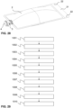
- a gauge device for determining a filling state of a bag, preferably of the inflatable bag of the storage assembly described above, is provided, the gauge device comprising a frame structure which defines an opening into which the bag can be placed,
- the frame structure may comprise a first frame bar delimiting the opening on a first side and a second frame bar delimiting the opening on a second side opposite to the first side.
- the first frame bar and the second frame bar are preferably movable with respect to each other, thereby changing the dimension of the opening.
- the filling state marker may comprise a ruler part connected to the first frame bar and a cursor part connected to the second frame bar, the cursor part being configured to slide along the ruler part when the first frame bar and the second frame bar are moving with respect to each other.
- the cursor part is provided by a slit in the second frame bar and the ruler part is provided by a strip being connected in a foldable manner to the first frame bar, the strip being insertable into the slit and slidable within the slit.
- the strip preferably comprises at least two, in particular three ruler sections, which may correspond to different inflation states of the bag that is to be inserted into the variable opening, such as "not sufficiently inflated”, “sufficiently inflated", "ideally inflated”.
- the ruler sections may be delimited by marker lines and/or may be colored differently and/or have text written on them.
- the gauge device is preferably made of cardboard or a cardboard-like material that is recyclable.
- the gauge device may comprise or consist of a flexible plastic material or a metal foil.
- a method of delivering a gas sample, preferably a breath gas sample, to an analyzer assembly comprising:
- the ionizer device may be configured as a secondary electro-spray ionization (SESI) device, which comprises a positive ionization mode ("positive mode”) in which positively charged ions are generated, and a negative ionization mode (“negative mode”), in which negatively charged ions are generated.
- SESI secondary electro-spray ionization
- the gas sample is provided in the storage assembly as described above, the bag being the inflatable bag of said storage assembly, wherein the sealing cap is connected to the input piece so as to seal the valve mechanism.
- the method may further comprise:
- the perforation device is insertable into the sealing cap such that a gas-tight connection between the perforation device and the sealing cap is formed prior to perforating the sealing membrane.
- the perforation device comprises a connector part and the step of establishing a gas-tight connection between the inflatable bag and the analyzer assembly comprises: establishing a gas-tight connection between the connector part of the perforation device and the analyzer assembly, preferably using a tube.
- the tube may be made of a flexible material such as polytetrafluoroethylene (PTFE).
- PTFE polytetrafluoroethylene
- the tube may be a metal tube.
- the tube may be heated and/or may comprise an appropriate coating which may reduce a loss of the analytes present in the gas. Ideally, the tube is be kept as short as possible to minimize the loss of analytes.
- the method may further comprise:
- Switching the ionizer device between a positive ionization mode and a negative ionization mode may be desirable in order to maximize the coverage of analytes which may be detected.
- the method does not comprise any steps to generate a pre-concentration of the analytes in the gas sample prior to entering the analyzer device, in particular prior to entering the ionizer device.
- the extraction device operates entirely on mechanical principles, i.e. without any electrical parts.
- the translatory movement of the squeezing structure may be driven by gravity.
- the extraction device may further comprise:
- Such a stop mechanism and trigger mechanism may be used when an interruption of the gas flow is desired, for example when the ionizer device, to which the gas is being delivered, is to be switched from the positive ionization mode to the negative ionization mode or vice versa.
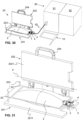
- Fig. 1 shows a schematic exploded view of a storage assembly 1 for storing a gas, preferably breath gas, according to a first embodiment of the first aspect of the present invention.
- the storage assembly comprises an inflatable bag 2, which is configured to contain the gas, an input piece 3, a sealing cap 4, and a perforation device 5.
- the storage assembly may further comprise a mouthpiece 6, which is connectable to the input piece 3 to enable a user to blow or exhale breath gas into the inflatable bag 2.
- the input piece 3, the sealing cap 4, the perforation device and the mouthpiece are configured to be assembled a long a common central axis C, as indicted in Fig. 1 .
- the input piece 3 comprises a valve mechanism having an open valve state in which a passage for the gas through the valve mechanism is open, and a closed valve state in which the passage for the gas through the valve mechanism is closed.
- the sealing cap 4 is removably connectable to the input piece 3 and comprises a sealing membrane 41 to prevent gas from passing through the valve mechanism when the sealing cap 4 is connected to the input piece 3.
- the perforation device 5 is insertable into the input piece 3, in particular when the sealing cap 4 is in place in the input piece 3, and comprises a perforation structure 50 which is configured to perforate the sealing membrane 41 when the sealing cap is connected to the input piece 3. Furthermore, the perforation device 5 is configured to cause the valve mechanism to be in the open valve state once the perforation device 5 is inserted in the input piece 3.
- Fig. 2 shows the storage assembly of Fig. 1 in an assembled state without the perforation device 5 and the mouthpiece 6.
- the inflatable bag 2 may be rectangular and have a fillable region with a long side having a length of 20 cm to 40 cm, preferably 30 cm and a short side having a width of 10 cm to 20 cm, preferably 14 cm.
- the bag 2 may be inflatable up to a maximum volume of up to 1.8 litres, preferably up to 1.4 liters or less.
- the inflatable bag 2 is essentially formed by a first sheet and a second sheet being connected, in particular glued and/or welded to each other along their edges.
- the input piece 3 is attached to the inflatable bag 2 in the center of the short side the embodiments shown here, but may however also be located elsewhere along the edge of the bag 2 or anywhere within the fillable region away from the edge.
- the inflatable bag 2 further comprises a fixation portion 21, which is preferably a non-inflatable strip, for instance formed by a region where the first and the second sheet are glued and/or welded to each other, wherein the strip comprises fixation holes 22 for fixing/mounting/suspending the bag 2 to a corresponding bag mounting structure to hold the bag 2 in place during a filling process and/or an extraction process.
- fixation portion 21 is arranged on a side of the filling region opposite to the input piece 3 and fixation portion 21 has two fixation holes 22.
- fixation portion 21 may also have just one fixation hole 22 or more than two fixation holes 22.
- the bag 2 may comprise loops and/or straps configured to fulfill the same purpose.
- connection structure 32 comprises ridges 321 extending on two opposite sides of the hollow shaft portion 30 to form a tapered, beak-like structure on each of the two opposite sides of the hollow shaft portion 30.
- the first sheet is attached to a top part 322 of the beak-like structure, while the second sheet is attached to a bottom part 323 of the beak-like structure, the top part 322 and the bottom part 323 of the beak-like structure converging towards each other to form a beak tip 324 on each of the two opposite sides of the hollow shaft portion 30 of the bag connection structure 32, as visible for instance in the front view of the input piece 3 shown in Fig. 4 .
- the input piece 3 further comprises a mounting feature 35, which may be used to mount to input piece 3 onto a holder (not shown) during filling and/or emptying of the bag 2.
- the input piece 3 comprises a separation wall 340 arranged within the hollow shaft portion, the separation wall 340 having passage holes 341 through which the gas may flow in and/or out of the bag 2.
- passage holes 341 are shown in
- a flap attachment structure 34 is formed at the center of the separation wall 340, the passage holes 341 being arranged in a ring-shaped manner around the flap attachment structure 34.
- Fig. 5 shows a separate view of a flap 33, which is configured to be attached to the flap attachment structure 34 to form a flap valve.
- the flap 33 has a disk shape defining a disk center and a circumferential edge region 331.
- a disk hole 332 is arranged at the disk center.
- Fig. 6 shows a sectional view of the input piece 3 with the flap 33 being attached to the flap attachment structure 34, the flap attachment structure 34 in this first embodiment comprising a nub protruding through the disk hole 332 of the disk-shaped flap 33, wherein the nub comprises a circumferential notch in which the flap 33 is received.
- Fig. 6 shows an open valve position in which the circumferential edge region 331 of the flap 33 is bent away from the separation wall 340 towards an interior of the bag due to a gas flow passing through the passage holes 341 in direction of the bag 2, i.e. in particular coming from a patient through the mouthpiece, and hitting the flap 33 as indicated by the dashed arrows in Fig. 6 .
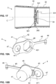
- Fig. 7 shows an enlarged perspective view of the first embodiment of the sealing cap 4 visible in Fig. 1 .
- the sealing cap 4 comprises a cap sleeve 42 in the form of a conical cup, wherein the sealing membrane 41 is arranged at a first end of the cap sleeve 42, i.e. forming the bottom of the cup.
- a cap rim 46 extends radially outwards from the cap sleeve 42 at a second end of the cap sleeve 42 opposite to the first end.
- the cap rim 46 has an alignment feature 43 in form of a notch, which is configured to engage with the input alignment feature 31 of the input piece, which is visible in Fig. 3 and Fig. 6 , to enable rotational alignment of the sealing cap 4 with respect to the input piece 3 when the sealing cap 4 is inserted into the input piece 3.
- the cap sleeve 42 comprises a retaining feature 44.
- the retaining feature 44 has the form of a retaining ring, the retaining feature 44 being connected to the cap rim 46 via a retaining feature connection part 45 in form of a bendable strip.
- the input piece 3 has a retaining notch 36 running circumferentially along an outer surface of the hollow shaft portion 30 to receive the retaining feature 44, i.e. the retaining ring.
- Fig. 8 shows a sectional view of the sealing cap 4 being inserted in the hollow shaft portion 30 of the input piece 3, wherein the cap rim 46 abuts on an abutment edge 37 of the hollow input shaft 30.
- the retaining ring 44 is received in the retaining notch 36 of the input piece 3.
- the bendable strip 45 is bent in a U-shape such that the cap sleeve 42 is arranged concentrically within the retaining ring 44, as visible for instance in Fig. 2 .
- the sealing membrane 41 abuts on the separation wall 340, i.e. is in direct contact with the latter, and thereby covers the passage holes 341 to seal the valve mechanism.
- Fig. 8 shows a sectional view of the sealing cap 4 being inserted in the hollow shaft portion 30 of the input piece 3, wherein the cap rim 46 abuts on an abutment edge 37 of the hollow input shaft 30.
- the retaining ring 44 is received in the retaining notch 36 of the input piece 3.
- the valve mechanism is shown in a closed valve state, i.e. the circumferential edge region 331 of the flap 33 is in plane with the disk center, wherein the circumferential edge region 331 of the flap 33 extends radially beyond the passage holes 341 and rests on the separation wall 340, thus covering the passage holes 341 from a side of the separation wall 340 that is opposite to the side of the separation wall that is configured to be covered by the sealing membrane 41.
- the gas is trapped inside the inflatable bag 2.
- Increasing a pressure of the gas inside the bag 2 leads to an increased pressure against the circumferential portion 331 of the flap 33, thus causing the latter to be pressed more strongly against the separation wall 340.
- the valve mechanism thus acts as a passive one-way valve, wherein the gas cannot exit the bag unless the flap 33 is forced open by external means, e.g. by the perforation device 5.
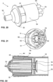
- Fig. 9 shows a separate perspective view of the first embodiment of the perforation device 5.
- Fig. 10 shows the same embodiment of the perforation device 5 under a different viewing angle than in Fig. 9 .
- the perforation device 5 comprises an insertion portion 54 in form of a shaft which is insertable into the cap sleeve 42 of the sealing cap 4.
- a perforation structure 50 is arranged at a first end of the insertion portion 54, the perforation structure 50 being configured to perforate the sealing membrane 41 and to cause the valve mechanism to be in the open valve state once the perforation device 5 is inserted in the input piece 3 when the sealing cap 4 is connected to the input piece 3.
- the perforation structure 50 comprises six perforation arms 53 which are arranged equidistantly from each other on a circle.
- Each perforation arm 53 comprises a triangular tip pointing radially inwards towards a center of the circle.
- An abutment ring 55 is arranged at a second end of the insertion portion 54 opposite to the perforation structure 50, the abutment ring being configured to abut on the cap rim 46 of the sealing cap 4 when the perforation device is inserted in the sealing cap 4, thus defining a maximum insertion depth.
- the insertion portion 54 comprises perforation guide structure 51 in the form of a groove running axially from the first end to the second end of the insertion portion 54, the groove being configured to engage with a cap guide structure 421, which in this first embodiment is a ridge formed on an inner surface of the cap sleeve 42, as shown in Fig. 7 .
- the perforation arms 53 are configured to punch trough the sealing membrane 41 and to subsequently bend the circumferential edge region 331 of the flap 33 towards the interior of the bag 2, so as uncover the passage holes 341 and thus enable the gas to exit the bag 2 through the passage holes 341 and the perforated sealing membrane 41.
- the perforation device 5 comprises an orifice 56 arranged at the second end of the insertion portion 54, the orifice 56 having a diameter which may be chosen to set a desired maximum flow velocity of the gas.
- the orifice 56 may have fixed diameter, as shown in Fig. 10 , or may be configured to have an adjustable diameter, in a manner similar to a shutter of a camera, in other embodiments (not shown).
- the perforation device 5 further comprises a connector part 52, preferably arranged downstream of the orifice 56 as shown in Figs. 9 and 11 , at the second end of the insertion portion 54.
- the connector part 52 is preferably configured to be connectable, either directly or via a connecting tube, to an analyzer assembly to analyze the gas exiting the bag 2.
- the connector part 52 may comprise a hollow shaft into which a tube may be inserted.
- the input piece 3, the sealing cap 4 and the perforation device are configured to form a gas-tight connection when properly assembled, i.e. such that the gas can only exit through the connector part 52 of the insertion device 5.
- the input alignment feature 31 of the second embodiment protrudes radially from the hollow shaft portion 30 with respect to the central axis C, while it protrudes axially in the first embodiment shown in Fig. 3 .
- the sealing cap 4 according to the second embodiment shown separately in Figs. 18A and 18B , comprises a cap retaining feature 44 that is shaped as a plug instead of a ring as in the first embodiment shown in Fig. 7 .
- the plug is insertable into a retaining plug hole 36', which is arranged in a ledge extending from an outer surface of the hollow shaft portion 30 of the second embodiment of the input piece 3, as shown in Figs. 13 and 14 .
- the sealing cap 4 according to the second embodiment comprises a handle portion 47, which is formed in once piece with the cap rim 46 and comprises a grip hole 471 configured to be gripped by a human finger.
- Fig. 19A shows a first sectional view of the sealing cap 4 being inserted in the hollow shaft portion 30 of the input piece 3, wherein the cap rim 46 abuts on an abutment edge 37 of the hollow input shaft 30.
- the sealing membrane 41 is not in direct contact with the separation wall 340, i.e. the sealing membrane 41 is arranged at a distance from the separation wall 340 when the sealing cap 4 is maximally inserted in the input piece 3.
- Fig. 19B shows a second sectional view of the sealing cap 4 being inserted in the hollow shaft portion 30 of the input piece 3 along a different sectional plane than in Fig. 19A , the sectional planes of Fig. 19A and Fig. 19B being orthogonal to each other.
- the valve mechanism is shown in a closed state.
- Fig. 19B shows the cap alignment feature 43 which, in contrast to the first embodiment, is arranged on a rear side of the rim 46, i.e. facing towards the first end of the cap sleeve 42 at which the sealing membrane 41 is arranged.
- the cap alignment feature 43 is visible in the view shown in Fig. 18B .
- the cap guide structure 421, which engages with the perforation guide structure 51 of the perforation device 5, also differs from the first embodiment: in the second embodiment, the cap guide structure 421 is formed by a guide section of the cap sleeve 42 having a noncircular cross section, in particular a hexagonal cross section, the guide section being arranged at the second end of the cap sleeve 42, i.e. opposite to the first end at which the sealing membrane 41 is arranged, as shown in Fig. 18A .
- the perforation device 5 of the second embodiment shown separately under two different angles in Figs.
- the sub-portion 51 comprises a sub-portion of the insertion portion 54 that acts as the perforation guide structure 51, the sub-portion 51 being shaped to fit into the guide section 421 of the cap sleeve 42 when properly oriented with respect to the cap sleeve.
- the sub-portion 51 has a hexagonal cross section as well if the cap guide structure 421 has a hexagonal cross section.
- the perforation device 5 of this second embodiment shown in Figs.
- 20 and 21 may be easier to align with respect to the cap sleeve 42, since it may be inserted into the cap sleeve 42 under six different rotation angles, as compared to having only one possible angular orientation defined by the engagement of the groove and the ridge in the first embodiment (see Figs. 7 and 9 ).
- Fig. 22 shows a sectional view of the input piece 3, the sealing cap 4 and the perforation device 5 of the second embodiment being assembled, i.e. wherein the perforation arms 53 are reaching through the ruptured sealing membrane 41 and forcing the circumferential edge region 331 of the flap 33 to uncover the passage holes 341 by bending the circumferential edge region 331 of the flap 3 towards the interior of the bag 2.
- the sectional plane in Fig. 22 is parallel to the central axis C, but arranged at a distance from the central axis C, in contrast to the sectional view of the first embodiment shown in Fig. 11 , where the sectional plane comprises the central axis C.
- the connector part 52 which is conically tapered in this second embodiment, is visible in the sectional view of Fig. 22 .
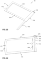
- the frame structure 11 comprises a fold 117, the fold 117 extending across the third frame bar 113 and the third frame bar 114 in a line that is parallel to the first 111 and the second 112 frame bar, and that is arranged equidistantly from the first 111 and the second 112 frame bar, such that the first frame bar 111 can be folded onto the second frame bar 112 to a folded state, in which the dimension of the opening is then reduced to zero.
- the gauge device 10 further comprises a filling state marker configured to indicate the dimension of the opening, the filling state marker in the present embodiment comprising a ruler part in the form of a strip 116 and a cursor part in the form of a slit 115 in the second frame 112 bar, into which the strip 116 can be inserted.
- the strip 116 extends perpendicularly away from the first frame bar 111 in the unfolded state so as to be in-line with the third frame bar 113, and the slit is arranged in a corner of the frame structure 11 shared by the second frame bar 112 and the third frame bar 113.
- the strip 116 is connected to the first frame bar 111 in a foldable manner, i.e.
- the strip comprises three ruler sections S1,S2,S3, which correspond to different inflation states of the bag 2 that is to be inserted into the variable opening, such as "not sufficiently inflated” S1, "sufficiently inflated” S2, "ideally inflated” S3.
- the ruler sections S1,S2,S3 may be delimited by marker lines and/or may be colored differently and/or have text written on them.
- the cursor i.e.
- the slit 115 is located in the different ruler section depending on the dimension of opening, i.e. here the distance between the first frame bar 111 and the second frame bar 112, thereby providing an indicating about the current dimension of the opening.
- the slit 115 may have a width that is larger than a thickness of the strip 116 to allow some mechanical play.
- the center of the slit 115 is marked by two arrows, i.e. one arrow being arranged on either side of the slit 115.
- Figs. 25-27 show the working principle of the gauge device 10 to determine the inflation state of the inflatable bag 2 of the first embodiment of the storage assembly 1 shown in Figs. 1-11 .
- the gauge device 10 may however be used in an equal manner for determining the inflation state of the inflatable bag 2 of the second embodiment of the storage assembly 1 shown in Figs. 12-22 .
- Fig. 25 depicts a pre-filling state, in which the inflatable bag 2 is empty and in which the cap sleeve 42 of the sealing cap 4 is not inserted in the input piece 3, but wherein the sealing cap 4 is nevertheless attached to the input piece 3 by the retaining feature 44, and wherein the mouthpiece 6 has been inserted into the input piece 3 to enable a user to exhale into the inflatable bag 2.
- the frame structure 11 of the gauge device 10 surrounds the bag 2, which is flat in the pre-filling state, such that the frame structure 11 is essentially in the folded state, with the strip 116 extending vertically upwards through the slit 115.
- Fig. 27 depicts an ideally-filled state, in which the inflatable bag 2 has been inflated to an ideal volume.
- the slit 115 is located in the third ruler section S3, which indicates that the bag 2 is ideally inflated.
- the bag 2 may be sealed by inserting the cap sleeve 42 of the sealing cap 4 into the input piece 3, as shown in Fig. 28 .
- the bag may be transported or shipped to an analyzer assembly for performing an analysis of the gas contained in the bag 2.
- a method of delivering a gas sample contained in a bag to an analyzer assembly is schematically represented as a flow diagram.
- Fig. 30 shows a setup in which said method may be performed, the setup comprising an extraction device 20 to extract the gas from the bag 2 in a controlled manner according to an embodiment of the fourth aspect of the present invention, and the analyzer assembly 80.
- the analyzer assembly in this example comprises an ionizer device 81 that is connected to a mass spectrometer 82.
- the ionizer device 81 is configured as a secondary electro-spray ionization (SESI) device, which comprises a positive ionization mode ("positive mode”), and a negative ionization mode ("negative mode").
- SESI secondary electro-spray ionization
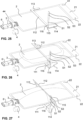
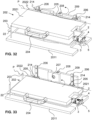
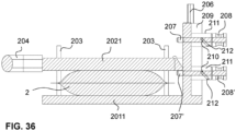
- a first embodiment of the extraction device 20 is shown in enlarged perspective views in Figs. 31-35 and in a sectional view in Fig. 36 .
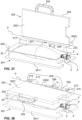
- a second embodiment of the extraction device 20 is shown in Figs. 37-42 .
- first embodiment of the extraction device 20 is shown together with the second embodiment of the storage assembly 1, while the second embodiment of the extraction device 20 is shown together with the first embodiment of the of the storage assembly 1.
- both the first and the second embodiment of the extraction device 20 can of course be used with either of the first and second embodiment of the storage assembly 1 shown in Figs. 1-22 , or with any other storage assembly that comprises a flexible bag.
- the extraction device 20 comprises a support structure 201 and a squeezing structure 202, wherein the support structure 201 and the squeezing structure 202 are arranged such that the bag 2 can be received between the support structure 201 and the squeezing structure 202.
- the squeezing structure is movable with respect to the support structure 201 from a start position to an end position and the squeezing structure is configured to exert pressure onto the bag 2 while moving from the start position to the end position to cause the gas sample contained in the bag 2 to exit the inflatable bag 2.
- a preferred embodiment of the method in which a breath gas sample is provided in the storage assembly of any of the embodiments described above, comprises the following steps schematically depicted in Fig. 29 :
- the switching step 1009 may also be omitted.
- pressure may be applied to the inflatable bag 2 already prior to opening the valve mechanism, i.e. prior to perforating the sealing membrane 41.
- the method may further comprise heating the gas-tight connection between the inflatable bag 2 and the analyzer assembly, in particular heating the tube 83.
- Fig. 31 and Fig. 37 show the first and the second embodiment, respectively, of the extraction device 20 in a bag loading position.
- the squeezing structure 202 is positioned such that the bag 2 can conveniently be placed onto the support structure 201.
- the squeezing structure 202 comprises a squeezing plate 2021, the squeezing plate 2021 being substantially rectangular except for a cut-out to accommodate the input piece 3 of the storage assembly 1, and a handle 204 attached to a first edge of the squeezing plate 2021, as well as a hinge mechanism 205 arranged on a second edge of the squeezing plate 2021 being opposite to the first edge.
- the support structure 201 comprises a support plate 2011, and the hinge mechanism 205 causes the squeezing plate 2021 to be pivotable about a pivot axis P which lies in a plane that is parallel to the support plate 2011.
- the squeezing plate 2021 may be pivoted by 90° about the pivot axis P from the bag loading position, in which the squeezing plate 2021 does not touch the bag 2, to a start position, which is depicted in Fig. 32 and Fig. 38 , in which the squeezing plate 202 and the support plate 2011 are parallel to each other.
- two mounting posts 203 are attached to the support plate 2011 so as to extend vertically from the support plate 2011, wherein the mounting posts 203 are separated by a distance that corresponds to a distance between the fixation holes 22 of the fixation portion of the bag 2.
- the bag 2 is then arranged such that each of the mounting posts 203 extends through one of the fixation holes 22 to prevent the bag 2 from moving off the support plate 2011.
- a single mounting post 203 may also be used instead, in particular if the fixation portion of the bag 2 only has one single fixation hole, the fixation hole being preferably arranged in the center of the fixation portion, and the single mounting post 203 being arranged accordingly on the support plate 2011.
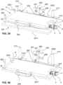
- the squeezing plate 202 is movable from the start position to an intermediate position, which is depicted in Fig. 33 and Fig. 39 , in which the bag 2 is partially deflated, i.e. in which a first predetermined portion of the gas sample has been extracted from the bag 2 and a second predetermined portion of the gas sample is still in the bag 2.
- the squeezing plate 202 of both embodiments of the extraction device 20 is further movable from the intermediate position to an end position, which is shown in Fig. 34 and Fig. 40 .
- the bag 2 is preferably maximally deflated, i.e. preferably all the gas has been extracted from the bag 2.
- the end position may however be conceivable for the end position to correspond to a state in which the bag 2 is not yet empty.
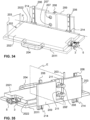
- the squeezing plate 202 moves from the start position to the intermediate position and further from the intermediate position to the end position by sliding along a guide system.
- the guide system comprises two rails 206.
- the two rails 206 run parallel to each other and are attached at a distance from each other to a wall structure 209, wherein the wall structure 209 is fixedly arranged with respect to the support plate 2011 and extends vertically from the latter.
- the guide system further comprises two slide carriages 214, wherein each slide carriage 214 is guided on one of the two rails 206.
- the guide system comprises two slide posts 213 extending vertically from the support plate 2011 and fixed at a distance from each other on the support plate 2011.
- the connection portion 2022 of the second embodiment comprises two slide holes, wherein each slide hole 215 is associated with one of the slide posts 213 such that each slide post 213 extends through one of the slide holes 215, thereby forming a gliding mechanism with a friction that is sufficiently low for the connection portion 2022 to be able to glide up and down the slide posts 213, thus enabling the squeezing plate 2021, which is attached to the connection portion 2022 via the hinge mechanism 205, to move up and down.
- the second embodiment of the extraction device 20 also comprises a wall structure 209 being fixedly arranged with respect to the support plate 2011 and extending vertically from the latter.
- wall structure 209 is arranged between the slide posts 213 and is not in direct contact with the slide posts 213.
- the movement of the squeezing structure 201 from the start position to the intermediate position and from the intermediate position to the end position is caused by gravity, i.e. the pressure applied to the bag 2 by the squeezing structure 202 while moving is determined by the weight of the squeezing structure 202 per area.
- the extraction device 20 comprises a stop mechanism.
- the extraction device 20 further also comprises a trigger mechanism configured to unlock the stop mechanism and thereby release the squeezing structure 202 from the intermediate position.
- the stop mechanism is further configured to keep the squeezing structure 202 in the start position and the trigger mechanism is further configured to release the squeezing structure 202 from the start position to allow it to move from the start position to the intermediate position.
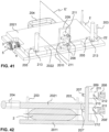
- the stop mechanism and the trigger mechanism are visible in the perspective front views shown of the extraction device 20 of the first and second embodiment in Fig. 34 and Fig. 40 , respectively, as well as in the perspective rear views shown in Fig. 35 and Fig. 41 , and in the sectional views shown in Fig. 36 and Fig. 42 .
- the stop mechanism comprises a first stop pin 207 and a second stop pin 207', both the first stop pin 207 and the second stop pin 207' being configured to protrude horizontally from the wall structure 209 in direction of the squeezing plate 2021 in an extended state to support the squeezing structure 202 from underneath the squeezing structure 202, and to be retractable into a retracted state in which the squeezing structure 202 is not supported and thus free to move, in particular to fall as driven by gravity.
- the first stop pin 207 is arranged vertically above the second stop pin 207'.
- the first stop pin 207 and the second stop pin 207' are arranged between the two rails 206, while in the second embodiment, the first stop pin 207 and the second stop pin 207' are arranged between the two slide posts 213.
- each of the first and second stop pin 207, 207' extends through a bayonet cylinder 211 that is fixedly arranged between the respective first and second trigger handle 208, 208' and a rear side of the wall structure 209, wherein the rear side is opposite to a front side of the wall structure 209, the front side facing the squeezing plate 2021.
- the bayonet cylinders 211 are attached to the rear side of the wall structure 209 so as to be non-rotatable.
- Each of the first and second stop pin 207,207' comprises a bayonet pin 210 extending at a right angle from the respective stop pin 207,207' and each bayonet cylinder 211 comprises a bayonet slit 212 with a first slit end and a second slit end.
- the bayonet pin 210 is located at the first slit end of the respective bayonet slit 212, the first slit end forming a notch in which the bayonet pin 210 is engaged.
- the first slit end is located closer to the rear side of the wall structure 209 than the second slid end.
- the stop pin 207,207' rotates together with the trigger handle 208,208' and the bayonet pin moves out of the notch at the first slit end and is guided along the bayonet slit towards the second slit end, causing the stop pin 207, 207' to retract, i.e. move away from the squeezing structure 202 so as to no longer support the squeezing structure 202, which is then free to move downwards.
Landscapes
- Health & Medical Sciences (AREA)
- Chemical & Material Sciences (AREA)
- Life Sciences & Earth Sciences (AREA)
- Chemical Kinetics & Catalysis (AREA)
- Clinical Laboratory Science (AREA)
- General Health & Medical Sciences (AREA)
- Pathology (AREA)
- Public Health (AREA)
- Biomedical Technology (AREA)
- Heart & Thoracic Surgery (AREA)
- Medical Informatics (AREA)
- Molecular Biology (AREA)
- Surgery (AREA)
- Animal Behavior & Ethology (AREA)
- Biophysics (AREA)
- Engineering & Computer Science (AREA)
- Veterinary Medicine (AREA)
- Physics & Mathematics (AREA)
- Pulmonology (AREA)
- Physiology (AREA)
- Analytical Chemistry (AREA)
- Hematology (AREA)
- Sampling And Sample Adjustment (AREA)
- Investigating Or Analysing Biological Materials (AREA)
Priority Applications (2)
| Application Number | Priority Date | Filing Date | Title |
|---|---|---|---|
| EP23179434.8A EP4477313A1 (de) | 2023-06-15 | 2023-06-15 | Vorrichtungen und verfahren im zusammenhang mit gasspeicherung |
| PCT/EP2024/066456 WO2024256587A2 (en) | 2023-06-15 | 2024-06-13 | Devices and methods related to gas storage |
Applications Claiming Priority (1)
| Application Number | Priority Date | Filing Date | Title |
|---|---|---|---|
| EP23179434.8A EP4477313A1 (de) | 2023-06-15 | 2023-06-15 | Vorrichtungen und verfahren im zusammenhang mit gasspeicherung |
Publications (1)
| Publication Number | Publication Date |
|---|---|
| EP4477313A1 true EP4477313A1 (de) | 2024-12-18 |
Family
ID=86942802
Family Applications (1)
| Application Number | Title | Priority Date | Filing Date |
|---|---|---|---|
| EP23179434.8A Withdrawn EP4477313A1 (de) | 2023-06-15 | 2023-06-15 | Vorrichtungen und verfahren im zusammenhang mit gasspeicherung |
Country Status (2)
| Country | Link |
|---|---|
| EP (1) | EP4477313A1 (de) |
| WO (1) | WO2024256587A2 (de) |
Citations (9)
| Publication number | Priority date | Publication date | Assignee | Title |
|---|---|---|---|---|
| US4443219A (en) * | 1981-03-10 | 1984-04-17 | C. R. Bard, Inc. | System for aseptically draining a urine bag |
| CA2043346A1 (en) * | 1991-05-27 | 1992-11-28 | Robina Bernard | Apparatus for measuring inflated balloons |
| US5728077A (en) * | 1992-10-15 | 1998-03-17 | Health Care Technology Australia Pty. Ltd. | Intravenous delivery system |
| US20020094396A1 (en) * | 2000-09-06 | 2002-07-18 | M & D Balloons, Inc. | Extended life balloon |
| US20140024130A1 (en) * | 2011-03-16 | 2014-01-23 | Contralco | Chemical breath testing device for detecting alcohol including a testing tube and an inflatable bag |
| US20140276100A1 (en) | 2012-02-01 | 2014-09-18 | Invoy Technologies | System for measuring breath analytes |
| US20190270096A1 (en) * | 2018-03-02 | 2019-09-05 | Thermo Electron Led Gmbh | Single-use centrifuge containers for separating biological suspensions and methods of use |
| WO2019177644A1 (en) * | 2018-03-15 | 2019-09-19 | Chris Marsh | Sample capture assembly for an aldehyde analysis system and method of use |
| KR20210069316A (ko) * | 2019-12-03 | 2021-06-11 | 주식회사 파이어시스 | 풍선 크기 측정 및 조절 장치 |
-
2023
- 2023-06-15 EP EP23179434.8A patent/EP4477313A1/de not_active Withdrawn
-
2024
- 2024-06-13 WO PCT/EP2024/066456 patent/WO2024256587A2/en active Pending
Patent Citations (9)
| Publication number | Priority date | Publication date | Assignee | Title |
|---|---|---|---|---|
| US4443219A (en) * | 1981-03-10 | 1984-04-17 | C. R. Bard, Inc. | System for aseptically draining a urine bag |
| CA2043346A1 (en) * | 1991-05-27 | 1992-11-28 | Robina Bernard | Apparatus for measuring inflated balloons |
| US5728077A (en) * | 1992-10-15 | 1998-03-17 | Health Care Technology Australia Pty. Ltd. | Intravenous delivery system |
| US20020094396A1 (en) * | 2000-09-06 | 2002-07-18 | M & D Balloons, Inc. | Extended life balloon |
| US20140024130A1 (en) * | 2011-03-16 | 2014-01-23 | Contralco | Chemical breath testing device for detecting alcohol including a testing tube and an inflatable bag |
| US20140276100A1 (en) | 2012-02-01 | 2014-09-18 | Invoy Technologies | System for measuring breath analytes |
| US20190270096A1 (en) * | 2018-03-02 | 2019-09-05 | Thermo Electron Led Gmbh | Single-use centrifuge containers for separating biological suspensions and methods of use |
| WO2019177644A1 (en) * | 2018-03-15 | 2019-09-19 | Chris Marsh | Sample capture assembly for an aldehyde analysis system and method of use |
| KR20210069316A (ko) * | 2019-12-03 | 2021-06-11 | 주식회사 파이어시스 | 풍선 크기 측정 및 조절 장치 |
Also Published As
| Publication number | Publication date |
|---|---|
| WO2024256587A3 (en) | 2025-01-23 |
| WO2024256587A2 (en) | 2024-12-19 |
Similar Documents
| Publication | Publication Date | Title |
|---|---|---|
| JP5558837B2 (ja) | インディケータを備える安全な採血アセンブリ | |
| US11642057B2 (en) | Devices, systems and methods for actuation and retraction in fluid collection | |
| AU2003203533B2 (en) | Blood collection set with venting mechanism | |
| US7883499B2 (en) | Vial adaptors and vials for regulating pressure | |
| KR101157810B1 (ko) | 의료 장치 패키지, 키트 및 관련 방법 | |
| DK2802377T3 (en) | Pressure regulating bottle adapter and method | |
| US20160338911A1 (en) | Anti-reflux vial adaptors | |
| EP0189118A2 (de) | Blutentnahmevorrichtung | |
| KR20050097882A (ko) | 자동 개방 의료 디바이스 패키지 및 제조 방법 | |
| US20050065454A1 (en) | Non-evacuated blood collection tube | |
| AU2010257251A1 (en) | Passive safety device for needle of blood collection set | |
| JPH0731607A (ja) | 息捕集装置及び吐息サンプル捕集方法 | |
| US9839488B2 (en) | Sterility cover for medical device surface | |
| US5467776A (en) | Air sampling device and method for sampling exhaled air | |
| EP4477313A1 (de) | Vorrichtungen und verfahren im zusammenhang mit gasspeicherung | |
| JP2019516533A (ja) | 血液採取装置およびシステム、およびその方法 | |
| US20200121233A1 (en) | Funnel with extension tube to augment blood collection device | |
| US20250020550A1 (en) | Sample collection device and system | |
| EP4683570A2 (de) | Probensammelvorrichtung und -system |
Legal Events
| Date | Code | Title | Description |
|---|---|---|---|
| PUAI | Public reference made under article 153(3) epc to a published international application that has entered the european phase |
Free format text: ORIGINAL CODE: 0009012 |
|
| STAA | Information on the status of an ep patent application or granted ep patent |
Free format text: STATUS: THE APPLICATION HAS BEEN PUBLISHED |
|
| AK | Designated contracting states |
Kind code of ref document: A1 Designated state(s): AL AT BE BG CH CY CZ DE DK EE ES FI FR GB GR HR HU IE IS IT LI LT LU LV MC ME MK MT NL NO PL PT RO RS SE SI SK SM TR |
|
| STAA | Information on the status of an ep patent application or granted ep patent |
Free format text: STATUS: THE APPLICATION IS DEEMED TO BE WITHDRAWN |
|
| 18D | Application deemed to be withdrawn |
Effective date: 20250619 |