EP4477276A2 - Fall detection alert/alarm device and method - Google Patents
Fall detection alert/alarm device and method Download PDFInfo
- Publication number
- EP4477276A2 EP4477276A2 EP24209772.3A EP24209772A EP4477276A2 EP 4477276 A2 EP4477276 A2 EP 4477276A2 EP 24209772 A EP24209772 A EP 24209772A EP 4477276 A2 EP4477276 A2 EP 4477276A2
- Authority
- EP
- European Patent Office
- Prior art keywords
- fall
- harness
- state
- length
- alert
- Prior art date
- Legal status (The legal status is an assumption and is not a legal conclusion. Google has not performed a legal analysis and makes no representation as to the accuracy of the status listed.)
- Pending
Links
Images



Classifications
-
- G—PHYSICS
- G08—SIGNALLING
- G08B—SIGNALLING SYSTEMS, e.g. PERSONAL CALLING SYSTEMS; ORDER TELEGRAPHS; ALARM SYSTEMS
- G08B25/00—Alarm systems in which the location of the alarm condition is signalled to a central station, e.g. fire or police telegraphic systems
- G08B25/01—Alarm systems in which the location of the alarm condition is signalled to a central station, e.g. fire or police telegraphic systems characterised by the transmission medium
- G08B25/016—Personal emergency signalling and security systems
-
- A—HUMAN NECESSITIES
- A62—LIFE-SAVING; FIRE-FIGHTING
- A62B—DEVICES, APPARATUS OR METHODS FOR LIFE-SAVING
- A62B35/00—Safety belts or body harnesses; Similar equipment for limiting displacement of the human body, especially in case of sudden changes of motion
- A62B35/0006—Harnesses; Accessories therefor
- A62B35/0018—Full body harnesses covering at least shoulders and thighs
-
- A—HUMAN NECESSITIES
- A62—LIFE-SAVING; FIRE-FIGHTING
- A62B—DEVICES, APPARATUS OR METHODS FOR LIFE-SAVING
- A62B35/00—Safety belts or body harnesses; Similar equipment for limiting displacement of the human body, especially in case of sudden changes of motion
- A62B35/0006—Harnesses; Accessories therefor
- A62B35/0025—Details and accessories
-
- A—HUMAN NECESSITIES
- A62—LIFE-SAVING; FIRE-FIGHTING
- A62B—DEVICES, APPARATUS OR METHODS FOR LIFE-SAVING
- A62B35/00—Safety belts or body harnesses; Similar equipment for limiting displacement of the human body, especially in case of sudden changes of motion
- A62B35/04—Safety belts or body harnesses; Similar equipment for limiting displacement of the human body, especially in case of sudden changes of motion incorporating energy absorbing means
Definitions
- This disclosure relates to personal protective equipment (PPE) and more particularly to fall protection equipment (FPE), and even more particularly to fall indicators/fall detection devices as used in connection with fall harnesses and other fall protection equipment.
- PPE personal protective equipment
- FPE fall protection equipment
- Fall harnesses are an example of a critical piece of fall protection safety equipment that are integral to preventing accidents on the job site. They provide a reliable restraint system worn by the worker that is connected to a fixed anchor point on a supporting structure. Fall harnesses are designed to arrest the fall of a worker quickly and safely but result in the worker being suspended in the fall harness. If there is no ladder or scaffolding for the worker to climb back up, the worker will remain suspended until additional rescue help can be rendered. Being suspended in the fall harness for an extended period of time can lead to serious injury or death. Consequently, rapid response is critical.
- a fall indicator in a fall harness to provide notice that a fall harness has experienced a arrested fall while worn by worker, with the fall indicator being formed by a folded length of one of the straps that forms the fall harness that is secured in the folded condition by a breakable connection that breaks when the harness experiences an arrested fall while worn by a worker.
- fall indicators have a label or other indicia that is exposed when the breakable connection is broken and the folded length of strap unfolds, with the now exposed label or other indicia providing notice that the harness has experienced an arrested fall. While the notice provided by the label/indicia is useful for preventing future use of the harness without understanding that the harnesses already experienced an arrested fall, the label/indicia does nothing to alert other personnel that a worker has experienced an arrested fall and may be suspended in the fall harness.
- a fall detection/fall indicator device that automatically senses when a user of fall protection equipment, such as a fall harness, has experienced an arrested fall and capable of providing an alarm/alert to other personnel so that they may provide assistance to the user in a timely fashion.
- a fall harness for use in fall protection.
- the fall harness includes a plurality of straps configured to attach the harness to a user and to other fall protection equipment.
- the harness further includes a fall indicator having a first state wherein the harness has not experienced an arrested fall, and a second state wherein the harness has experienced an arrested fall while worn by a user.
- the fall indicator includes a length of one of the straps, the length having a folded condition in the first state wherein the length is folded upon itself and maintained in the folded condition by a connection that breaks in response to the harness experiencing an arrested fall while worn by a user, and an unfolded condition in the second state wherein the connection is broken and the length unfolded in response to an arrested fall experienced by the harness while worn by a user.
- the fall indicator further includes an electrical connection having a pair of electrical contacts that are contacted together to form a closed circuit in the first state and that are spaced from each other in the second state to form an open circuit.
- the contacts are mounted on the length of strap so that the contacts face each other in adjacent portions of the length of strap in the folded condition and are contacted together to form the closed circuit, and so that the contacts are spaced from each other with the length of strap in the unfolded condition to form the open circuit.
- the fall indicator further includes an alert device operably connected to the electrical connection and responsive to the open circuit to provide an alert to other personnel that the fall indicator is in the second state after the harness experiences an arrested fall while worn by a user.
- the electrical connection includes a snap fastener having a post component defining one of the contacts, and a socket component defining the other contact and configured to releasably receive the post component.
- a processing unit is operably connected to the electrical connection to detect the open circuit and to the alarm device to initiate the alert in response to detection of the open circuit.
- the processing unit is a microprocessor unit.
- a housing mounts at least one of the processing unit and the alert device to the harness. In a further feature, the housing is fixed on the length of strap.
- the alert device is configured to emit an audible acoustic alert.
- the alert device includes a siren device.
- the alert device is configured to emit a visual alert.
- the alert device includes a strobe light device.
- the alert device is configured to emit a wireless signal that can be detected by a device remote from the harness to alert the device that the fall indicator is in the second state.
- the alert device includes a wireless transmitter.
- the harness includes at least one more fall indicator.
- a method of providing an alert that a piece of fall protection equipment has experienced an arrested fall while worn or used by a user including a fall indicator having a first state wherein the piece of fall protection equipment has not experienced an arrested fall, and a second state wherein the piece of fall protection equipment has experienced an arrested fall while worn or used by a user.
- the method includes the steps of electronically detecting a change of the fall indicator from the first state to the second state, and automatically initiating an alert in response to the step of electronically detecting.
- the step of electronically detecting includes creating an open circuit in response to the change of the fall indicator from the first state to the second state.
- a method of providing an alert that a piece of fall protection equipment has experienced an arrested fall while worn or used by a user includes the steps of providing the piece of fall protection equipment with an electrical circuit that is closed in a first state wherein the piece of fall protection equipment has not experienced an arrested fall, and that is open in a second state wherein the piece of fall protection equipment has experienced an arrested fall while worn or used by a user, and automatically initiating an alert in response to the open circuit.
- a fall indicator for use on a piece of fall protection equipment to provide an alert to other personnel that a worker using or wearing the piece of fall protection equipment has experienced an arrested fall.
- the fall indicator has a first state wherein the piece of fall protection equipment has not experienced an arrested fall, and a second state wherein the harness has experienced an arrested fall while worn or used by a worker.
- the fall indicator includes a length of strap, the length having a folded condition in the first state wherein the length is folded upon itself and maintained in the folded condition by a connection that breaks in response to the piece of fall protection equipment experiencing an arrested fall, and an unfolded condition in the second state wherein the connection is broken and the length unfolded in response to an arrested fall.
- the fall indicator further includes an electrical connection having a pair of electrical contacts that are contacted together to form a closed circuit in the first date and that our spaced from each other in the second state to form an open circuit.
- the contacts are mounted on the length of strap so that the contacts face each other in adjacent portions of the length of strap in the folded condition and are contacted together to form the closed circuit, and so that the contacts are spaced from each other with the length of strap in the unfolded condition to form the open circuit.
- the fall indicator further includes an alert device operably connected to the electrical connection and responsive to the open circuit to provide an alert to other personnel that the fall indicator is in the second state after the piece of fall protection equipment experiences an arrested fall.
- an item of personal protective equipment (PPE) for providing fall protection is shown as a piece of fall protection equipment (FPE) in the form of a safety/fall harness 10 for use in fall protection.
- the safety harness includes a plurality of straps 12 configured to attach the harness 10 to a worker/user 14 and to other fall protection equipment, such as, for example, an anchor, a fall protection lanyard, or a self retracting lifeline.
- PPE personal protective equipment
- FPE fall protection equipment
- the safety harness includes a plurality of straps 12 configured to attach the harness 10 to a worker/user 14 and to other fall protection equipment, such as, for example, an anchor, a fall protection lanyard, or a self retracting lifeline.
- the harness depicted in Fig. 1 is for purposes of illustration and further specific details of the fall harness 10 will not be discussed herein except for those required for an understanding of the disclosed concepts, and that the appended claims are not limited to any specific details of a fall harness unless expressly recited in the claims.
- One or more fall protection/fall indicator devices 20 are provided at one or more corresponding key locations on the harness 10 where the harness 10 will experience a shock load when a user 14 of the harness 10 experiences an arrested fall.
- Each of the fall indicators 20 has a first state wherein the user 14 and the harness 10 have not experienced an arrested fall, and a second state wherein the user 14 and the harness 10 have experienced an arrested fall. In the second state, each of the fall indicators 20 provide an alarm/alert to other personnel that the user 14 has experienced an arrested fall, thereby enabling such personnel to provide assistance to the user 14 in a timely fashion.
- fall harnesses are well known and because they can be, and are, provided in a number of different configurations with different details that are compatible with the concepts of this disclosure, and further because the details of the safety harness 10 outside of the fall indicator 20 are not critical to understanding the fall indicator 20 and the method according to this disclosure, further details of the harness 10 outside of the fall indicator 20 will not be provided herein.
- Figs. 2A and 2B show the details of one of the fall indicators 20, and it should be understood that these details are consistent for all of the fall indicators 20 provided on the harness 10.
- the fall indicator 20 includes a length 22 of one of the straps 12, the length 22 having a folded condition in the first state shown in Fig. 2A wherein the length 22 is folded upon itself and maintained in the folded condition by a breakable or releasable connection 24 that breaks or releases in response to the harness 10 and the user 14 experiencing an arrested fall, and an unfolded condition in the second state shown in Fig. 2B wherein the connection 24 is broken and the length 22 unfolded in response to an arrested fall experienced by the harness 10 in the user 14.
- connection 24 is provided in the form of two spaced lines of stitching 26 that extend through and connect adjacent portions 28, 30, and 32 of the length 22 at folds 34 of the fall indicator 20 in the folded condition.
- proper selection of materials and stitch configuration will allow the lines of stitching 26 to break when the length 22 of strapping 12 experiences a predetermined tensile shock load F that corresponds to the expected load that will be experienced during an arrested fall.
- connection 24 in the form of the pair of spaced lines of stitching 26
- suitable forms of the connection 24 are contemplated within the scope of this disclosure, such as, for example, a single line of stitching, bonding agents or adhesive, and/or one or more breakable/releasable rivet connections.
- the fall indicator 20 includes an electrical connection 40 having a pair of electrical contacts 42 and 44 that are part of an electrical circuit, shown schematically at 45 in Figs. 2A and 2B .
- the electrical contacts 42 and 44 are connected together to form a closed circuit, shown schematically at 46 in Fig. 2A , in the first state and folded condition, and that are spaced from each other in the second state and unfolded condition to form an open circuit, shown schematically at 48 in Fig. 2B .
- the contacts 42 and 44 are mounted on the length 22 of strap 12 so that the contacts 42 and 44 face each other in adjacent portions 28 and 30 of the length 22 in the folded condition and are contacted together to form the closed circuit 46, as shown in Fig. 2A , and so that the contacts 42 and 44 will be spaced from each other to form the open circuit 48 when the length 22 of strap 12 is in the unfolded condition, as shown in Fig. 2B .
- the electrical connection 40 is provided in the form of an electrically conductive snap fastener 50 having an electrically conductive post component 52 defining one of the contacts 42 and an electrically conductive socket component 54 defining the other of the contacts 44 and configured to releasably receive a post 56 of the post component 52, with the engagement of the post 56 and the socket component 54 forming an electrically conductive connection.
- the post 56 in the illustrated embodiment of the snap fastener 50, includes a detent 57 that is movable past a detent 58 in the socket component 54 due to the resiliency of either the remainder of the post 56 or the remainder of the socket component 54.
- the fall indicator 20 further includes an electronics module 60 that at least includes an alert device 62 operably connected to the electrical connection 40 and responsive to the open circuit 48 to automatically provide an alert that the fall indicator 20 is in the second state after the harness 10 and the user 14 have experienced an arrested fall.
- an electronics module 60 that at least includes an alert device 62 operably connected to the electrical connection 40 and responsive to the open circuit 48 to automatically provide an alert that the fall indicator 20 is in the second state after the harness 10 and the user 14 have experienced an arrested fall.
- the electronics module 60 further includes a processing unit provided in the form of a microprocessor unit (MPU) 64 operably connected to the electrical connection 40 to automatically detect the open circuit 48 and operably connected to the alert device 62 to automatically initiate the alert in response to detection of the open circuit 48.
- MPU microprocessor unit
- the MPU 64 it will be desirable for the MPU 64 to be a very low power consumption MPU that is configured to wake up periodically to sense the condition of the fall indicator 20.
- the open circuit 48 is detected as a change in voltage at DI in the MPU 64 relative to the closed circuit 46 voltage at DI.
- a housing 66 is fixed on the length 22 of strap 12 and mounts and encloses the alert device 62 and the processing unit 64.
- the alert device 62 is configured to emit all three of the visual alert, audible acoustic alert, and wireless signal.
- the alert device 62 will include a siren device 68, of which many suitable types and configurations are known, with a high power siren device 68 capable of producing an 85 dB audible noise being desirable in many applications.
- the alert device 62 will include a strobe light device 70, of which many suitable types and configurations are known.
- a method 74 for providing an alert that a fall harness 10 or other piece of fall protection equipment (FPE) 10 has experienced an arrested fall while worn or used by a user/worker 14.
- the method includes the step 76 of providing the piece of fall protection equipment 10 with an electrical circuit 45 that is closed in a first state wherein the piece of fall protection equipment 10 has not experienced an arrested fall, and that is open in a second state wherein the piece of fall protection equipment 10 has experienced an arrested fall while worn or used by a user 14.
- the method 74 further includes the step 78 of automatically initiating an alert in response to the open circuit.
- the step 82 of electronically detecting includes creating 86 an open circuit 48 in response to the change of the fall indicator 20 from the first state to the second state.
- the electronics module 60 has been shown as being fixed to the fall indicator 20, the electronics module 60 could be fixed to other portions of the harness 10.
- the electronics module 60 has been shown as being mounted and enclosed in a single housing 66, the electronics module 60 could be mounted and enclosed in multiple housings.
- the illustrated embodiments show the alert device 62 as being connected to the electrical connection 40 via the MPU 64 and initiated by the MPU 64, other operable connections are contemplated that would initiate the alert device 62 in response to the open circuit 48.
- the illustrated embodiment of the electrical connection 40 is shown in the form of a snap fastener 50, other suitable forms of electrical connections having a pair of electrical contacts that can be connected in the first state and disconnected in the second state are contemplated within the scope of this disclosure.
- the fall indicator 20 has been disclosed herein in connection with a fall harness 10, use of the fall indicator 20 with other types of fall protection equipment, such as, for example, fall protection lanyards and SRL's, is contemplated within the scope of this disclosure.
Landscapes
- Business, Economics & Management (AREA)
- Emergency Management (AREA)
- Health & Medical Sciences (AREA)
- General Health & Medical Sciences (AREA)
- Engineering & Computer Science (AREA)
- Computer Security & Cryptography (AREA)
- Physics & Mathematics (AREA)
- General Physics & Mathematics (AREA)
- Emergency Lowering Means (AREA)
- Alarm Systems (AREA)
- Emergency Alarm Devices (AREA)
Abstract
Description
- This application claims the benefit of the filing date of
U.S. Provisional Serial No. 62/273,853, filed December 31, 2015 - Not Applicable.
- Not Applicable.
- This disclosure relates to personal protective equipment (PPE) and more particularly to fall protection equipment (FPE), and even more particularly to fall indicators/fall detection devices as used in connection with fall harnesses and other fall protection equipment.
- Fall harnesses are an example of a critical piece of fall protection safety equipment that are integral to preventing accidents on the job site. They provide a reliable restraint system worn by the worker that is connected to a fixed anchor point on a supporting structure. Fall harnesses are designed to arrest the fall of a worker quickly and safely but result in the worker being suspended in the fall harness. If there is no ladder or scaffolding for the worker to climb back up, the worker will remain suspended until additional rescue help can be rendered. Being suspended in the fall harness for an extended period of time can lead to serious injury or death. Consequently, rapid response is critical.
- It is known to provide a fall indicator in a fall harness to provide notice that a fall harness has experienced a arrested fall while worn by worker, with the fall indicator being formed by a folded length of one of the straps that forms the fall harness that is secured in the folded condition by a breakable connection that breaks when the harness experiences an arrested fall while worn by a worker. Typically, such fall indicators have a label or other indicia that is exposed when the breakable connection is broken and the folded length of strap unfolds, with the now exposed label or other indicia providing notice that the harness has experienced an arrested fall. While the notice provided by the label/indicia is useful for preventing future use of the harness without understanding that the harnesses already experienced an arrested fall, the label/indicia does nothing to alert other personnel that a worker has experienced an arrested fall and may be suspended in the fall harness.
- A fall detection/fall indicator device is provided that automatically senses when a user of fall protection equipment, such as a fall harness, has experienced an arrested fall and capable of providing an alarm/alert to other personnel so that they may provide assistance to the user in a timely fashion.
- In accordance with one feature of this disclosure, a fall harness is provided for use in fall protection. The fall harness includes a plurality of straps configured to attach the harness to a user and to other fall protection equipment. The harness further includes a fall indicator having a first state wherein the harness has not experienced an arrested fall, and a second state wherein the harness has experienced an arrested fall while worn by a user. The fall indicator includes a length of one of the straps, the length having a folded condition in the first state wherein the length is folded upon itself and maintained in the folded condition by a connection that breaks in response to the harness experiencing an arrested fall while worn by a user, and an unfolded condition in the second state wherein the connection is broken and the length unfolded in response to an arrested fall experienced by the harness while worn by a user. The fall indicator further includes an electrical connection having a pair of electrical contacts that are contacted together to form a closed circuit in the first state and that are spaced from each other in the second state to form an open circuit. The contacts are mounted on the length of strap so that the contacts face each other in adjacent portions of the length of strap in the folded condition and are contacted together to form the closed circuit, and so that the contacts are spaced from each other with the length of strap in the unfolded condition to form the open circuit. The fall indicator further includes an alert device operably connected to the electrical connection and responsive to the open circuit to provide an alert to other personnel that the fall indicator is in the second state after the harness experiences an arrested fall while worn by a user.
- As one feature, the electrical connection includes a snap fastener having a post component defining one of the contacts, and a socket component defining the other contact and configured to releasably receive the post component.
- In one feature, a processing unit is operably connected to the electrical connection to detect the open circuit and to the alarm device to initiate the alert in response to detection of the open circuit. According to a further feature, the processing unit is a microprocessor unit. As one feature, a housing mounts at least one of the processing unit and the alert device to the harness. In a further feature, the housing is fixed on the length of strap.
- According to one feature, the alert device is configured to emit an audible acoustic alert. As a further feature, the alert device includes a siren device.
- In one feature, the alert device is configured to emit a visual alert. According to a further feature, the alert device includes a strobe light device.
- As one feature, the alert device is configured to emit a wireless signal that can be detected by a device remote from the harness to alert the device that the fall indicator is in the second state. In a further feature, the alert device includes a wireless transmitter.
- According to one feature, the harness includes at least one more fall indicator.
- As one feature, a method of providing an alert that a piece of fall protection equipment has experienced an arrested fall while worn or used by a user is provided. The piece of fall protection equipment including a fall indicator having a first state wherein the piece of fall protection equipment has not experienced an arrested fall, and a second state wherein the piece of fall protection equipment has experienced an arrested fall while worn or used by a user. The method includes the steps of electronically detecting a change of the fall indicator from the first state to the second state, and automatically initiating an alert in response to the step of electronically detecting.
- In one feature, the step of electronically detecting includes creating an open circuit in response to the change of the fall indicator from the first state to the second state.
- According to one feature, a method of providing an alert that a piece of fall protection equipment has experienced an arrested fall while worn or used by a user is provided. The method includes the steps of providing the piece of fall protection equipment with an electrical circuit that is closed in a first state wherein the piece of fall protection equipment has not experienced an arrested fall, and that is open in a second state wherein the piece of fall protection equipment has experienced an arrested fall while worn or used by a user, and automatically initiating an alert in response to the open circuit.
- As one feature, a fall indicator is provided for use on a piece of fall protection equipment to provide an alert to other personnel that a worker using or wearing the piece of fall protection equipment has experienced an arrested fall. The fall indicator has a first state wherein the piece of fall protection equipment has not experienced an arrested fall, and a second state wherein the harness has experienced an arrested fall while worn or used by a worker. The fall indicator includes a length of strap, the length having a folded condition in the first state wherein the length is folded upon itself and maintained in the folded condition by a connection that breaks in response to the piece of fall protection equipment experiencing an arrested fall, and an unfolded condition in the second state wherein the connection is broken and the length unfolded in response to an arrested fall. The fall indicator further includes an electrical connection having a pair of electrical contacts that are contacted together to form a closed circuit in the first date and that our spaced from each other in the second state to form an open circuit. The contacts are mounted on the length of strap so that the contacts face each other in adjacent portions of the length of strap in the folded condition and are contacted together to form the closed circuit, and so that the contacts are spaced from each other with the length of strap in the unfolded condition to form the open circuit. The fall indicator further includes an alert device operably connected to the electrical connection and responsive to the open circuit to provide an alert to other personnel that the fall indicator is in the second state after the piece of fall protection equipment experiences an arrested fall.
- Other features and advantages will become apparent from a review of the entire specification, including the appended claims and drawings.
-
-
Fig. 1 is a somewhat diagrammatic representation of a fall harness employing a fall detection/fall indicator device according to this disclosure; -
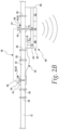
Figs. 2A and2B are enlarged, somewhat diagrammatical, section views take him along line 2-2 inFig. 1 and showing details of the fall detection/fall indicator device according to this disclosure, withFig. 2A showing the fall indicator device in a first state/folded condition andFig. 2B showing the fall indicator device in a second state/unfolded condition; -
Figs. 3 and 4 are diagrammatic representations of a method for providing an alert that a user of fall protection equipment has experienced and arrested fall according to this disclosure. - With reference to
Fig. 1 , an item of personal protective equipment (PPE) for providing fall protection is shown as a piece of fall protection equipment (FPE) in the form of a safety/fall harness 10 for use in fall protection. The safety harness includes a plurality ofstraps 12 configured to attach theharness 10 to a worker/user 14 and to other fall protection equipment, such as, for example, an anchor, a fall protection lanyard, or a self retracting lifeline. It should be understood that many types and configurations of safety/fall harnesses are known in the PPE and FPE industry, including full body harnesses and partial or hip/waist fall harnesses, all, or most, of which are suitable for use with the concepts disclosed herein, accordingly, the harness depicted inFig. 1 is for purposes of illustration and further specific details of thefall harness 10 will not be discussed herein except for those required for an understanding of the disclosed concepts, and that the appended claims are not limited to any specific details of a fall harness unless expressly recited in the claims. - One or more fall protection/
fall indicator devices 20 are provided at one or more corresponding key locations on theharness 10 where theharness 10 will experience a shock load when auser 14 of theharness 10 experiences an arrested fall. Each of thefall indicators 20 has a first state wherein theuser 14 and theharness 10 have not experienced an arrested fall, and a second state wherein theuser 14 and theharness 10 have experienced an arrested fall. In the second state, each of thefall indicators 20 provide an alarm/alert to other personnel that theuser 14 has experienced an arrested fall, thereby enabling such personnel to provide assistance to theuser 14 in a timely fashion. Because fall harnesses are well known and because they can be, and are, provided in a number of different configurations with different details that are compatible with the concepts of this disclosure, and further because the details of thesafety harness 10 outside of thefall indicator 20 are not critical to understanding thefall indicator 20 and the method according to this disclosure, further details of theharness 10 outside of thefall indicator 20 will not be provided herein. -
Figs. 2A and2B show the details of one of thefall indicators 20, and it should be understood that these details are consistent for all of thefall indicators 20 provided on theharness 10. Thefall indicator 20 includes alength 22 of one of thestraps 12, thelength 22 having a folded condition in the first state shown inFig. 2A wherein thelength 22 is folded upon itself and maintained in the folded condition by a breakable orreleasable connection 24 that breaks or releases in response to theharness 10 and theuser 14 experiencing an arrested fall, and an unfolded condition in the second state shown inFig. 2B wherein theconnection 24 is broken and thelength 22 unfolded in response to an arrested fall experienced by theharness 10 in theuser 14. - In the illustrated embodiment, the
connection 24 is provided in the form of two spaced lines of stitching 26 that extend through and connectadjacent portions length 22 atfolds 34 of thefall indicator 20 in the folded condition. As is known, proper selection of materials and stitch configuration will allow the lines of stitching 26 to break when thelength 22 of strapping 12 experiences a predetermined tensile shock load F that corresponds to the expected load that will be experienced during an arrested fall. It should be appreciated that while the illustrated embodiment shows theconnection 24 in the form of the pair of spaced lines of stitching 26 other suitable forms of theconnection 24 are contemplated within the scope of this disclosure, such as, for example, a single line of stitching, bonding agents or adhesive, and/or one or more breakable/releasable rivet connections. - The
fall indicator 20 includes anelectrical connection 40 having a pair ofelectrical contacts Figs. 2A and2B . Theelectrical contacts Fig. 2A , in the first state and folded condition, and that are spaced from each other in the second state and unfolded condition to form an open circuit, shown schematically at 48 inFig. 2B . Thecontacts length 22 ofstrap 12 so that thecontacts adjacent portions length 22 in the folded condition and are contacted together to form the closedcircuit 46, as shown inFig. 2A , and so that thecontacts open circuit 48 when thelength 22 ofstrap 12 is in the unfolded condition, as shown inFig. 2B . - In the illustrated embodiment, the
electrical connection 40 is provided in the form of an electricallyconductive snap fastener 50 having an electricallyconductive post component 52 defining one of thecontacts 42 and an electricallyconductive socket component 54 defining the other of thecontacts 44 and configured to releasably receive apost 56 of thepost component 52, with the engagement of thepost 56 and thesocket component 54 forming an electrically conductive connection. Although it is not known for such snap fasteners to be used as an electrical connection, the garment industry is replete with many known suitable, electrically conductive configurations and types of such snap fasteners, any of which may be utilized in thefall indicator 20 according to this disclosure depending upon the particular requirements of each application and, accordingly, the details of the illustratedsnap fastener 50 are not important to an understanding of the concepts disclosed and claimed herein and the claims are not limited to any particular detail unless expressly stated in the claims. Having said that, as best seen inFig. 2B , in the illustrated embodiment of thesnap fastener 50, thepost 56 includes adetent 57 that is movable past adetent 58 in thesocket component 54 due to the resiliency of either the remainder of thepost 56 or the remainder of thesocket component 54. - In the illustrated embodiment, the
fall indicator 20 further includes anelectronics module 60 that at least includes analert device 62 operably connected to theelectrical connection 40 and responsive to theopen circuit 48 to automatically provide an alert that thefall indicator 20 is in the second state after theharness 10 and theuser 14 have experienced an arrested fall. - In the illustrated embodiment, the
electronics module 60 further includes a processing unit provided in the form of a microprocessor unit (MPU) 64 operably connected to theelectrical connection 40 to automatically detect theopen circuit 48 and operably connected to thealert device 62 to automatically initiate the alert in response to detection of theopen circuit 48. In this regard, in some embodiments, it will be desirable for theMPU 64 to be a very low power consumption MPU that is configured to wake up periodically to sense the condition of thefall indicator 20. In the illustrated embodiment, theopen circuit 48 is detected as a change in voltage at DI in theMPU 64 relative to theclosed circuit 46 voltage at DI. In the illustrated embodiment, ahousing 66 is fixed on thelength 22 ofstrap 12 and mounts and encloses thealert device 62 and theprocessing unit 64. - In some embodiments, the
alert device 62 is configured to emit an audible acoustic alert/alarm that is detectable by personnel remote from theuser 14. In some embodiments, thealert device 62 is configured to emit a visual alert that is detectable by personnel remote from theuser 14. In some embodiments, thealert device 62 is configured to emit a wireless signal that can be detected by a device or devices (not shown) remote from theharness 10 and theuser 14 to alert the remote device(s) that thefall indicator 20 is in the second state and that theuser 14 has experienced an arrested fall. The remote device(s) may be in the form of one or more wireless phones (cell phones) that have a fall detection application software and that are carried by remote personnel, by a receiver that has an embedded acoustic alert device/generator, or/and a relay device that will relay the wireless signal to a cloud server or similar device configured to distribute the wireless signal, including the identification of the fallen user to the fallen user's supervisor and/or rescuers. In some embodiments, thealert device 62 is configured to emit at least two of the visual alert, audible acoustic alert, and wireless signal. In some embodiments, the alert device is configured to emit just one of the visual alert, audible acoustic alert, and wireless signal. In some embodiments, thealert device 62 is configured to emit all three of the visual alert, audible acoustic alert, and wireless signal. In some embodiments wherein thealert device 62 is configured to emit an audible acoustic alert, thealert device 62 will include asiren device 68, of which many suitable types and configurations are known, with a highpower siren device 68 capable of producing an 85 dB audible noise being desirable in many applications. In some embodiments wherein thealert device 62 is configured to emit a visual alert, thealert device 62 will include astrobe light device 70, of which many suitable types and configurations are known. It will be desirable in some applications for thestrobe light device 70 to be positioned so that it reflects of the material of the strap(s) 12 to further enhance the illumination. In some embodiments wherein thealert device 62 is configured to emit a wireless signal, thealert device 62 will include awireless transmitter 72, of which many suitable types and configurations are known. - With reference to
Fig. 3 , amethod 74 is shown for providing an alert that afall harness 10 or other piece of fall protection equipment (FPE) 10 has experienced an arrested fall while worn or used by a user/worker 14. The method includes thestep 76 of providing the piece offall protection equipment 10 with anelectrical circuit 45 that is closed in a first state wherein the piece offall protection equipment 10 has not experienced an arrested fall, and that is open in a second state wherein the piece offall protection equipment 10 has experienced an arrested fall while worn or used by auser 14. Themethod 74 further includes the step 78 of automatically initiating an alert in response to the open circuit. - With reference to
Fig. 4 , amethod 80 is shown for providing an alert that afall harness 10 or other piece of fall protection equipment has experienced an arrested the fall when worn or used by auser 14, the piece offall protection equipment 10 including afall indicator 20 having a first state wherein the piece offall protection equipment 10 has not experienced a fall, and a second state wherein the piece offall protection equipment 10 has experienced a fall while worn or used byuser 14. The method includes the steps of: - electronically detecting 82 a change of the
fall indicator 20 from the first state to the second state; and - automatically initiating 84 an alert in response to the step on electronically detecting.
- In a further embodiment of the
method 80, thestep 82 of electronically detecting includes creating 86 anopen circuit 48 in response to the change of thefall indicator 20 from the first state to the second state. - While several embodiments have been shown and discussed herein, it should be understood that this disclosure contemplates modifications to those embodiments. For example, while the
electronics module 60 has been shown as being fixed to thefall indicator 20, theelectronics module 60 could be fixed to other portions of theharness 10. As another example, while theelectronics module 60 has been shown as being mounted and enclosed in asingle housing 66, theelectronics module 60 could be mounted and enclosed in multiple housings. As a further example, while the illustrated embodiments show thealert device 62 as being connected to theelectrical connection 40 via theMPU 64 and initiated by theMPU 64, other operable connections are contemplated that would initiate thealert device 62 in response to theopen circuit 48. As yet a further example, while the illustrated embodiment of theelectrical connection 40 is shown in the form of asnap fastener 50, other suitable forms of electrical connections having a pair of electrical contacts that can be connected in the first state and disconnected in the second state are contemplated within the scope of this disclosure. As yet another example, while thefall indicator 20 has been disclosed herein in connection with afall harness 10, use of thefall indicator 20 with other types of fall protection equipment, such as, for example, fall protection lanyards and SRL's, is contemplated within the scope of this disclosure. As a further example, while the breakable/releasable connection 24 is shown the form of two lines of stitching 26 that extend through three layers oflength 22 ofstrap 12, it is possible for either or both of the lines of stitching 26 to extend only through two layers of the length ofstrap 12, or for the connection to be a single line of stitching that extends only through two layers of the length ofstrap 12. - Embodiments of the invention extend to the following statements:-
- 1. A fall harness (10) for use in fall protection, the fall harness (10) comprising:
- a plurality of straps (12) configured to attach the harness (10) to a user (14) and to other fall protection equipment; and
- a fall indicator (20) having a first state wherein the harness (10) has not experienced an arrested fall, and a second state wherein the harness (10) has experienced an arrested fall while worn by a user (14), the fall indicator (20) comprising:
- a length (22) of one of the straps (12), the length (22) having a folded condition in the first state wherein the length (22) is folded upon itself and maintained in the folded condition by a connection (24) that breaks in response to the harness (10) experiencing an arrested fall while worn by a user (14), and an unfolded condition in the second state wherein the connection (24) is broken and the length (22) unfolded in response to an arrested fall experienced by the harness (10) while worn by a user (14);
- an electrical connection (40) having a pair of electrical contacts (42,44) that are contacted together to form a closed circuit (46) in the first state and that are spaced from each other in the second state to form an open circuit (48), the contacts (42,44) mounted on the length (22) of strap (12) so that the contacts (42,44) face each other in adjacent portions (28,30) of the length (22) of strap (12) in the folded condition and are contacted together to form the closed circuit (46), and so that the contacts (42,44) are spaced from each other with the length (22) of strap (12) in the unfolded condition to form the open circuit (48); and
- an alert device (62) operably connected to the electrical connection (40) and responsive to the open circuit (48) to provide an alert to other personnel that the fall indicator (20) is in the second state after the harness (10) experiences an arrested fall while worn by a user (14).
- 2. The harness (10) of statement 1 wherein the electrical connection (40) comprises a snap fastener (50) having a post component (52) defining one of the contacts (42,44) and a socket component (54) defining the other contact and configured to releasably receive the post component (52).
- 3. The harness (10) of statement 1 further comprising:
- a processing unit (64) operably connected to the electrical connection (40) to detect the open circuit (48) and to the alert device (62) to initiate the alert in response to detection of the open circuit (48); and
- a housing (66) mounting at least one of the processing unit (64) and the alert device (62) to the harness (10).
- 4. The harness (10) of statement 3 wherein the housing (66) is fixed on the length (22) of strap (12).
- 5. The harness (10) of statement 1 wherein the alert device (62) is configured to emit an audible acoustic alert.
- 6. The harness (10) of statement 5 comprises a siren device (68).
- 7. The harness (10) of statement 1 wherein the alert device (62) is configured to emit a visual alert.
- 8. The harness (10) of statement 7 wherein the alert device (62) comprises a strobe light device (70).
- 9. The harness (10) of statement 1 wherein the alert device (62) is configured to emit a wireless signal that can be detected by a device (62) remote from the harness (10) to alert the device (62) that the fall indicator (20) is in the second state.
- 10. The harness (10) of statement 9 wherein the alert device (62) comprises a wireless transmitter (72).
- 11. The harness (10) of statement 1 further comprising at least one more fall indicator (20).
- 12. A method of providing an alert that a piece of fall protection equipment has experienced an arrested fall while worn or used by a user (14), the piece of fall protection equipment including a fall indicator (20) having a first state wherein the piece of fall protection equipment has not experienced an arrested fall, and a second state wherein the piece of fall protection equipment has experienced an arrested fall while worn or used by a user (14), the method comprising the steps of:
- electronically detecting a change of the fall indicator (20) from the first state to the second state; and
- automatically initiating an alert in response to the step of electronically detecting.
- 13. The method of
statement 12 wherein the step of electronically detecting comprises creating an open circuit (48) in response to the change of the fall indicator (20) from the first state to the second state. - 14. A method for providing an alert that a piece of fall protection equipment has experienced and arrested fall while worn or used by a user (14), the method includes the steps of:
- providing the piece of fall protection equipment with an electrical circuit (45) that is closed in a first state wherein the piece of fall protection equipment has not experienced an arrested fall, and that is open in a second state wherein the piece of fall protection equipment has experienced an arrested fall while worn or used by a user (14); and
- automatically initiating an alert in response to the open circuit (48).
- 15. A fall indicator (20) for use on a piece of fall protection equipment to provide an alert to other personnel that a worker using are wearing the piece of fall protection equipment has experienced an arrested fall, the fall indicator (20) having a first state wherein the piece of fall protection equipment has not experienced an arrested fall, and a second state wherein the piece of fall protection equipment has experienced an arrested fall while worn or used by a worker, the fall indicator (20) comprising:
- a length (22) of strap (12), the length (22) having a folded condition in the first state wherein the length (22) is folded upon itself and maintained in the folded condition by a connection (24) that breaks in response to the piece of fall protection equipment experiencing an arrested fall, and an unfolded condition in the second state wherein the connection (24) is broken and the length (22) unfolded in response to an arrested fall;
- an electrical connection (40) having a pair of electrical contacts (42,44) that are contacted together to form a closed circuit (46) in the first date and that our spaced from each other in the second state to form an open circuit (48), the contacts (42,44) mounted on the length (22) of strap (12) so that the contacts (42,44) face each other in adjacent portions (28,30) of the length (22) of strap (12) in the folded condition and are contacted together to form the closed circuit (46), and so that the contacts (42,44) are spaced from each other with the length (22) of strap (12) in the unfolded condition to form the open circuit (48); and
- an alert device (62) operably connected to the electrical connection (40) and responsive to the open circuit (48) to provide an alert to other personnel that the fall indicator (20) is in the second state after the piece of fall protection equipment experiences an arrested fall.
Claims (15)
- A harness for arresting a user's fall, the harness comprising:a length of strap configured to secure the harness to a securing point, the length of strap having a folded configuration in a first state and an unfolded configuration in a second state;a breakable connection configured to maintain the length of strap in the first state and to break to allow the length of strap to unfold from the first state to the second state in response to the user experiencing an arrested fall;a first electrical contact mounted on a first portion of the length of strap and a second electrical contact mounted on a second portion of the length of strap adjacent the first portion of the length of strap such that, in the first configuration, the first electrical contact is electrically coupled to the second electrical contact to form a closed circuit and, in the second configuration, the first electrical contact is electrically decoupled from the second electrical contact to form an open circuit; andan alert device operably connected to the first electrical contact and second electrical contact and configured to provide an alert when the length of strap is transitioned from the first configuration to the second configuration.
- The harness of claim 1, wherein the breakable connection comprises a snap fastener having a post component defining one of the contacts and a socket component defining the other contact and configured to releasably receive the post component.
- The harness of claim 1, further comprising:a processing unit operably connected to the breakable connection to detect the open circuit and to the alert device to initiate the alert in response to detection of the open circuit; anda housing mounting at least one of the processing unit and the alert device to the harness.
- The harness of claim 3, wherein the housing is fixed on the length of strap.
- The harness of claim 1, wherein the alert device is configured to emit an audible acoustic alert.
- The harness of claim 5, further comprising:
a siren device. - The harness of claim 1, wherein the alert device is configured to emit a visual alert.
- The harness of claim 7, wherein the alert device comprises a strobe light device.
- The harness of claim 1, wherein the alert device is configured to emit a wireless signal that can be detected by a device remote from the harness to alert the device that the electrical contacts are in the second configuration.
- The harness of claim 9, wherein the alert device comprises a wireless transmitter.
- The harness of claim 9, wherein the device remote from harness is in the form of one or more wireless phones that have a fall detection application software.
- The harness of claim 1, wherein the breakable connection, the first and second electrical contacts and the alert device together form a fall indicator and further comprising:
at least one more fall indicator. - A method of providing an alert that a piece of fall protection equipment has experienced an arrested fall while worn or used by a user, the piece of fall protection equipment comprising:a fall indicator having a first state wherein the piece of fall protection equipment has not experienced an arrested fall and a second state wherein the piece of fall protection equipment has experienced an arrested fall while worn or used by a user, the fall indicator comprising:a length of one of the straps , the length having a folded condition in the first state wherein the length is folded upon itself and maintained in the folded condition by a connection that breaks in response to the harness experiencing an arrested fall while worn by a user , and an unfolded condition in the second state wherein the connection is broken and the length unfolded in response to an arrested fall experienced by the harness while worn by a user; andan electrical connection having a pair of electrical contacts that are contacted together to form a closed circuit in the first state and that are spaced from each other in the second state to form an open circuit, the contacts mounted on the length of strap so that the contacts face each other in adjacent portions of the length of strap in the folded condition and are contacted together to form the closed circuit, and so that the contacts are spaced from each other with the length of strap in the unfolded condition to form the open circuit;electronically detecting a change of the fall indicator from the first state to the second state; andautomatically initiating an alert in response to the step of electronically detecting.
- The method of claim 12, wherein electronically detecting includes creating an open circuit in response to the change of the fall indicator from the first state to the second state.
- A method for providing an alert that a piece of fall protection equipment has experienced an arrested fall while worn or used by a user, the method comprising:providing the piece of fall protection equipment, the piece of fall protection equipment comprising:a fall indicator having a first state wherein the piece of fall protection equipment has not experienced an arrested fall and a second state wherein the piece of fall protection equipment has experienced an arrested fall while worn or used by a user, the fall indicator comprising:a length of one of the straps , the length having a folded condition in the first state wherein the length is folded upon itself and maintained in the folded condition by a connection that breaks in response to the harness experiencing an arrested fall while worn by a user , and an unfolded condition in the second state wherein the connection is broken and the length unfolded in response to an arrested fall experienced by the harness while worn by a user; andan electrical connection having a pair of electrical contacts that are contacted together to form a closed circuit in the first state and that are spaced from each other in the second state to form an open circuit, the contacts mounted on the length of strap so that the contacts face each other in adjacent portions of the length of strap in the folded condition and are contacted together to form the closed circuit, and so that the contacts are spaced from each other with the length of strap in the unfolded condition to form the open circuit; andautomatically initiating an alert in response to the open circuit.
Applications Claiming Priority (3)
| Application Number | Priority Date | Filing Date | Title |
|---|---|---|---|
| US201562273853P | 2015-12-31 | 2015-12-31 | |
| EP16819753.1A EP3397355B1 (en) | 2015-12-31 | 2016-12-01 | Fall detection alert/alarm device and method |
| PCT/US2016/064332 WO2017116603A1 (en) | 2015-12-31 | 2016-12-01 | Fall detection alert/alarm device and method |
Related Parent Applications (2)
| Application Number | Title | Priority Date | Filing Date |
|---|---|---|---|
| EP16819753.1A Division EP3397355B1 (en) | 2015-12-31 | 2016-12-01 | Fall detection alert/alarm device and method |
| EP16819753.1A Division-Into EP3397355B1 (en) | 2015-12-31 | 2016-12-01 | Fall detection alert/alarm device and method |
Publications (2)
| Publication Number | Publication Date |
|---|---|
| EP4477276A2 true EP4477276A2 (en) | 2024-12-18 |
| EP4477276A3 EP4477276A3 (en) | 2025-01-22 |
Family
ID=57680517
Family Applications (2)
| Application Number | Title | Priority Date | Filing Date |
|---|---|---|---|
| EP24209772.3A Pending EP4477276A3 (en) | 2015-12-31 | 2016-12-01 | Fall detection alert/alarm device and method |
| EP16819753.1A Active EP3397355B1 (en) | 2015-12-31 | 2016-12-01 | Fall detection alert/alarm device and method |
Family Applications After (1)
| Application Number | Title | Priority Date | Filing Date |
|---|---|---|---|
| EP16819753.1A Active EP3397355B1 (en) | 2015-12-31 | 2016-12-01 | Fall detection alert/alarm device and method |
Country Status (4)
| Country | Link |
|---|---|
| US (4) | US10223898B2 (en) |
| EP (2) | EP4477276A3 (en) |
| CN (1) | CN108697911B (en) |
| WO (1) | WO2017116603A1 (en) |
Cited By (1)
| Publication number | Priority date | Publication date | Assignee | Title |
|---|---|---|---|---|
| US20240307717A1 (en) * | 2023-03-19 | 2024-09-19 | Paul Lingo | Personal Fall Arrest Assembly |
Families Citing this family (12)
| Publication number | Priority date | Publication date | Assignee | Title |
|---|---|---|---|---|
| WO2016094437A1 (en) * | 2014-12-08 | 2016-06-16 | Fire Innovations Llc | Firefighter multifunction ladder and escape belt |
| KR20190068583A (en) * | 2016-10-14 | 2019-06-18 | 쓰리엠 이노베이티브 프로퍼티즈 캄파니 | Method and apparatus for generating energy using a fall arrestor |
| US12412464B2 (en) | 2019-01-14 | 2025-09-09 | Msa Technology, Llc | Fall protection compliance system and method |
| US12429494B2 (en) | 2019-01-14 | 2025-09-30 | Msa Technology, Llc | Fall protection compliance system and method |
| EP4600928A3 (en) | 2019-01-14 | 2026-02-25 | MSA Technology, LLC | Fall protection compliance system and method |
| US20220088425A1 (en) * | 2019-02-19 | 2022-03-24 | 3M Innovative Properties Company | Systems and methods for monitoring the condition of a fall - protection safety system |
| US11247080B2 (en) * | 2019-10-10 | 2022-02-15 | Saudi Arabian Oil Company | Systems, methods, and apparatuses for ensuring worker safety |
| GB202001028D0 (en) * | 2020-01-24 | 2020-03-11 | Beacon Group Int Products Ltd | Fall arrest indicator |
| CN114034422B (en) * | 2021-11-25 | 2024-09-06 | 安丹达工业技术(上海)有限公司 | Safety belt falling impact indicating device |
| WO2024018325A1 (en) * | 2022-07-20 | 2024-01-25 | 3M Innovative Properties Company | Composite connector comprising deformable section with interruptible signal-transmissive pathway |
| US12586963B2 (en) * | 2022-07-24 | 2026-03-24 | Lenovo (Singapore) Pte. Ltd | Electrical connector having an anomaly alert system and a brittle membrane |
| KR102870713B1 (en) * | 2024-11-19 | 2025-10-16 | (주)디아이지엔지니어링건축사사무소 | On-site lighting belt with improved operator safety and workability |
Family Cites Families (18)
| Publication number | Priority date | Publication date | Assignee | Title |
|---|---|---|---|---|
| US3875450A (en) | 1973-02-26 | 1975-04-01 | Rca Corp | Cathode-ray tube with radiation-emitting index strip-like areas |
| JPH0947522A (en) * | 1995-08-10 | 1997-02-18 | Takatsugu Oizumi | Safety belt |
| US8061479B2 (en) * | 2004-04-06 | 2011-11-22 | Harris Jr Rano J | Fall protection system |
| AU2006207863B2 (en) * | 2006-02-21 | 2009-05-07 | Fall Alert Industries Pty Ltd | Fall notifying apparatus |
| AU2007292897B2 (en) * | 2006-09-08 | 2012-04-26 | Honeywell Safety Products Usa, Inc. | Safety harnesses, connective ring attachments for use in safety harnesses and back pads for use in safety harnesses |
| US8292028B2 (en) * | 2006-09-11 | 2012-10-23 | Tech Safety Lines, Inc. | Fall arrest lanyard |
| JP2008259866A (en) * | 2008-04-17 | 2008-10-30 | Takatsugu Oizumi | Multifunctional safety belt |
| US8106864B2 (en) | 2008-10-10 | 2012-01-31 | Lg Display Co., Ltd. | Liquid crystal display device |
| US8325053B2 (en) * | 2009-03-10 | 2012-12-04 | JCJ Inc. | Personal fall protection monitoring system |
| JP5116815B2 (en) * | 2009-10-20 | 2013-01-09 | 藤井電工株式会社 | Safety belt and its usage confirmation system |
| US8902074B2 (en) * | 2010-08-26 | 2014-12-02 | Honeywell International, Inc. | Harness for fall protection |
| JP5311426B2 (en) * | 2011-12-27 | 2013-10-09 | ニチユ三菱フォークリフト株式会社 | Picking forklift safety device |
| CN103366504B (en) * | 2013-06-26 | 2015-09-02 | 重庆工业设备安装集团有限公司 | Longitudinal-transvedual-lifeline dual-lifeline protection alarm system |
| CN204073176U (en) * | 2014-08-07 | 2015-01-07 | 上海旭富实业有限公司 | A kind of fall arrest mark of safety belt |
| CN204147453U (en) * | 2014-10-28 | 2015-02-11 | 国核工程有限公司 | One is fallen sound and light alarm buffer-type safety belt |
| US20160150360A1 (en) * | 2014-11-22 | 2016-05-26 | Fearless Technology, LLC | Canopy tracking device for skydiving equipment |
| CN204582358U (en) * | 2015-04-20 | 2015-08-26 | 国家电网公司 | A kind of suspension safety belt with warning function |
| CN105126270A (en) * | 2015-08-31 | 2015-12-09 | 国网山东桓台县供电公司 | Intelligent anti-falling pole climbing tower protective device of power system and safety pole climbing method thereof |
-
2016
- 2016-12-01 WO PCT/US2016/064332 patent/WO2017116603A1/en not_active Ceased
- 2016-12-01 CN CN201680082848.0A patent/CN108697911B/en active Active
- 2016-12-01 EP EP24209772.3A patent/EP4477276A3/en active Pending
- 2016-12-01 EP EP16819753.1A patent/EP3397355B1/en active Active
- 2016-12-01 US US16/067,441 patent/US10223898B2/en active Active
-
2019
- 2019-01-18 US US16/251,613 patent/US10431072B2/en active Active
- 2019-08-19 US US16/543,804 patent/US10650664B2/en active Active
-
2020
- 2020-04-10 US US16/845,941 patent/US11024153B2/en active Active
Cited By (2)
| Publication number | Priority date | Publication date | Assignee | Title |
|---|---|---|---|---|
| US20240307717A1 (en) * | 2023-03-19 | 2024-09-19 | Paul Lingo | Personal Fall Arrest Assembly |
| US12544606B2 (en) * | 2023-03-19 | 2026-02-10 | Paul Lingo | Personal fall arrest system with transmitting alert module |
Also Published As
| Publication number | Publication date |
|---|---|
| US20190012900A1 (en) | 2019-01-10 |
| US20190371159A1 (en) | 2019-12-05 |
| US20200242915A1 (en) | 2020-07-30 |
| US11024153B2 (en) | 2021-06-01 |
| WO2017116603A1 (en) | 2017-07-06 |
| CN108697911A (en) | 2018-10-23 |
| US20190156656A1 (en) | 2019-05-23 |
| US10431072B2 (en) | 2019-10-01 |
| EP3397355A1 (en) | 2018-11-07 |
| US10650664B2 (en) | 2020-05-12 |
| CN108697911B (en) | 2021-06-29 |
| US10223898B2 (en) | 2019-03-05 |
| EP3397355B1 (en) | 2025-01-29 |
| EP4477276A3 (en) | 2025-01-22 |
Similar Documents
| Publication | Publication Date | Title |
|---|---|---|
| US11024153B2 (en) | Fall detection alert/alarm device and method | |
| US8928482B2 (en) | Personal fall protection system monitoring | |
| EP3138610B1 (en) | Safety equipment | |
| US11730984B2 (en) | Weight bearing fall protection connector having a wireless fall indicator | |
| US10729922B2 (en) | Fall protection radio frequency emergency beacon | |
| WO2012158554A2 (en) | Fall safety apparatus and method | |
| KR101803319B1 (en) | An attachable air bag system on safety harness | |
| EP3178527B1 (en) | Fall protection harness with damage indicator | |
| EP3178528B1 (en) | Fall protection harness with damage indicator | |
| CN111315452A (en) | Safety harness, safety equipment including safety harness, and protection method | |
| EP3199205B1 (en) | Fall protection harness with damage indicator | |
| CN214312029U (en) | Anti-falling system | |
| US20130154825A1 (en) | Hazard/perimeter safety system | |
| KR20210050730A (en) | Alarm apparatus for preventing the fall of the high place operator |
Legal Events
| Date | Code | Title | Description |
|---|---|---|---|
| PUAI | Public reference made under article 153(3) epc to a published international application that has entered the european phase |
Free format text: ORIGINAL CODE: 0009012 |
|
| STAA | Information on the status of an ep patent application or granted ep patent |
Free format text: STATUS: THE APPLICATION HAS BEEN PUBLISHED |
|
| AC | Divisional application: reference to earlier application |
Ref document number: 3397355 Country of ref document: EP Kind code of ref document: P |
|
| AK | Designated contracting states |
Kind code of ref document: A2 Designated state(s): AL AT BE BG CH CY CZ DE DK EE ES FI FR GB GR HR HU IE IS IT LI LT LU LV MC MK MT NL NO PL PT RO RS SE SI SK SM TR |
|
| REG | Reference to a national code |
Ref country code: DE Ref legal event code: R079 Free format text: PREVIOUS MAIN CLASS: A62B0035040000 Ipc: A62B0035000000 |
|
| PUAL | Search report despatched |
Free format text: ORIGINAL CODE: 0009013 |
|
| AK | Designated contracting states |
Kind code of ref document: A3 Designated state(s): AL AT BE BG CH CY CZ DE DK EE ES FI FR GB GR HR HU IE IS IT LI LT LU LV MC MK MT NL NO PL PT RO RS SE SI SK SM TR |
|
| RIC1 | Information provided on ipc code assigned before grant |
Ipc: A62B 35/04 20060101ALI20241218BHEP Ipc: A62B 35/00 20060101AFI20241218BHEP |
|
| RAP1 | Party data changed (applicant data changed or rights of an application transferred) |
Owner name: HONEYWELL SAFETY PRODUCTS USA, INC. |
|
| STAA | Information on the status of an ep patent application or granted ep patent |
Free format text: STATUS: REQUEST FOR EXAMINATION WAS MADE |
|
| 17P | Request for examination filed |
Effective date: 20250721 |