EP3199205B1 - Fall protection harness with damage indicator - Google Patents
Fall protection harness with damage indicator Download PDFInfo
- Publication number
- EP3199205B1 EP3199205B1 EP17153064.5A EP17153064A EP3199205B1 EP 3199205 B1 EP3199205 B1 EP 3199205B1 EP 17153064 A EP17153064 A EP 17153064A EP 3199205 B1 EP3199205 B1 EP 3199205B1
- Authority
- EP
- European Patent Office
- Prior art keywords
- fall protection
- thread
- protection harness
- electrically
- fall
- Prior art date
- Legal status (The legal status is an assumption and is not a legal conclusion. Google has not performed a legal analysis and makes no representation as to the accuracy of the status listed.)
- Active
Links
- 230000006378 damage Effects 0.000 title claims description 37
- 230000008859 change Effects 0.000 claims description 8
- 238000000034 method Methods 0.000 claims description 8
- 230000008569 process Effects 0.000 claims description 7
- 230000008878 coupling Effects 0.000 claims description 6
- 238000010168 coupling process Methods 0.000 claims description 6
- 238000005859 coupling reaction Methods 0.000 claims description 6
- 238000004519 manufacturing process Methods 0.000 claims description 5
- 239000004677 Nylon Substances 0.000 description 5
- 229920001778 nylon Polymers 0.000 description 5
- 230000032683 aging Effects 0.000 description 4
- 239000004020 conductor Substances 0.000 description 4
- 230000003068 static effect Effects 0.000 description 4
- BQCADISMDOOEFD-UHFFFAOYSA-N Silver Chemical compound [Ag] BQCADISMDOOEFD-UHFFFAOYSA-N 0.000 description 3
- 230000004044 response Effects 0.000 description 3
- 229910052709 silver Inorganic materials 0.000 description 3
- 239000004332 silver Substances 0.000 description 3
- 208000027418 Wounds and injury Diseases 0.000 description 2
- 230000001010 compromised effect Effects 0.000 description 2
- 208000014674 injury Diseases 0.000 description 2
- 230000004048 modification Effects 0.000 description 2
- 238000012986 modification Methods 0.000 description 2
- 230000003287 optical effect Effects 0.000 description 2
- 229910001220 stainless steel Inorganic materials 0.000 description 2
- 239000010935 stainless steel Substances 0.000 description 2
- 230000000007 visual effect Effects 0.000 description 2
- RYGMFSIKBFXOCR-UHFFFAOYSA-N Copper Chemical compound [Cu] RYGMFSIKBFXOCR-UHFFFAOYSA-N 0.000 description 1
- RTAQQCXQSZGOHL-UHFFFAOYSA-N Titanium Chemical compound [Ti] RTAQQCXQSZGOHL-UHFFFAOYSA-N 0.000 description 1
- 229910052782 aluminium Inorganic materials 0.000 description 1
- XAGFODPZIPBFFR-UHFFFAOYSA-N aluminium Chemical compound [Al] XAGFODPZIPBFFR-UHFFFAOYSA-N 0.000 description 1
- 238000010276 construction Methods 0.000 description 1
- 229910052802 copper Inorganic materials 0.000 description 1
- 239000010949 copper Substances 0.000 description 1
- 238000001514 detection method Methods 0.000 description 1
- 238000010586 diagram Methods 0.000 description 1
- 238000000605 extraction Methods 0.000 description 1
- 239000000835 fiber Substances 0.000 description 1
- PCHJSUWPFVWCPO-UHFFFAOYSA-N gold Chemical compound [Au] PCHJSUWPFVWCPO-UHFFFAOYSA-N 0.000 description 1
- 239000010931 gold Substances 0.000 description 1
- 229910052737 gold Inorganic materials 0.000 description 1
- 238000002955 isolation Methods 0.000 description 1
- 229910052751 metal Inorganic materials 0.000 description 1
- 239000002184 metal Substances 0.000 description 1
- 229920000728 polyester Polymers 0.000 description 1
- 239000011435 rock Substances 0.000 description 1
- 238000007790 scraping Methods 0.000 description 1
- 238000000926 separation method Methods 0.000 description 1
- 238000009958 sewing Methods 0.000 description 1
- 229910052719 titanium Inorganic materials 0.000 description 1
- 239000010936 titanium Substances 0.000 description 1
Images

Classifications
-
- G—PHYSICS
- G08—SIGNALLING
- G08B—SIGNALLING OR CALLING SYSTEMS; ORDER TELEGRAPHS; ALARM SYSTEMS
- G08B21/00—Alarms responsive to a single specified undesired or abnormal condition and not otherwise provided for
- G08B21/18—Status alarms
-
- A—HUMAN NECESSITIES
- A62—LIFE-SAVING; FIRE-FIGHTING
- A62B—DEVICES, APPARATUS OR METHODS FOR LIFE-SAVING
- A62B35/00—Safety belts or body harnesses; Similar equipment for limiting displacement of the human body, especially in case of sudden changes of motion
- A62B35/0006—Harnesses; Accessories therefor
- A62B35/0025—Details and accessories
-
- A—HUMAN NECESSITIES
- A62—LIFE-SAVING; FIRE-FIGHTING
- A62B—DEVICES, APPARATUS OR METHODS FOR LIFE-SAVING
- A62B35/00—Safety belts or body harnesses; Similar equipment for limiting displacement of the human body, especially in case of sudden changes of motion
- A62B35/0006—Harnesses; Accessories therefor
-
- A—HUMAN NECESSITIES
- A62—LIFE-SAVING; FIRE-FIGHTING
- A62B—DEVICES, APPARATUS OR METHODS FOR LIFE-SAVING
- A62B35/00—Safety belts or body harnesses; Similar equipment for limiting displacement of the human body, especially in case of sudden changes of motion
- A62B35/0043—Lifelines, lanyards, and anchors therefore
Definitions
- the present disclosure relates to fall protection harnesses and fall protection static lines, and in an embodiment, but not by way of limitation, a fall protection harness and fall protection static line with a damage indicator.
- Fall protection harnesses and fall protection static lines are critical pieces of safety equipment that are integral to preventing accidents on a job site.
- Fall protection harnesses provide a reliable restraint system worn by a worker that is connected to a fixed anchor point on a supporting structure, such as a building under construction.
- Fall protection harnesses are designed to arrest a fall of a worker quickly and safely.
- the fall protection harness causes a worker to be suspended in the fall protection harness in a potentially dangerous predicament. If there is no ladder or scaffolding for the worker to climb back onto, the worker will remain suspended until additional help can arrive. Being suspended in the fall protection harness for an extended period of time can lead to serious injury or death.
- US2012/050036 discloses a safety harness includes at least one of integrally formed electrical conductors or optical conductors, which can be energized by a replaceable electrical supply. Consequently, a rapid response is crucial to the safety of the worker. Also, a fall protection harness can be damaged or compromised when a fall occurs, or damaged or compromised as the fall protection harness ages. Such damage and/or compromising caused by a fall or aging should be brought to the attention of the proper person or authority, and the fall protection harness should be inspected and/or retired from use.
- An embodiment includes a sensor that is integrated into or attached to a fall protection harness and/or a fall protection static line.
- the sensor is capable of automatically sensing damage to the fall protection harness, aging of the fall protection harness, and/or a fall by a person wearing the fall protection harness.
- damage or aging is sensed, the fall protection harness can be examined to determine if it is still fit for further use.
- a responsible person can be immediately notified of the fall event so that the person in the harness can be assisted, and thereafter the fall protection harness can be examined for damaged and/or retired from use. Notifying a responsible person of a fall event reduces the response time for help to arrive and consequently reduces the amount of time the person is suspended in the fall protection harness.
- a fall protection harness is constructed of a nylon strap. At key locations on the harness, the nylon strap is folded over and attached (e.g., by sewing) onto itself to create a first portion of a damage or fall indicator.
- a second portion of the damage or fall indicator is a combination of an electrically conducting thread and an electrically non-conducting thread (the combination is for ease of thread breaking as nylon thread has more strength than the conductive thread and provides better isolation and separation when the conductive thread is broken) that is sewn into the fall protection harness.
- the electrically conducting thread is coupled to an electrical sensing device. In an embodiment, the electrically conducting thread and the electrically non-conducting thread are sewn into the fall protection harness at the folded over portion of the fall protection harness.
- the electrically non-conducting thread causes damage to and/or a break in the electrically conducting thread, which is sensed by the electrical sensing device, and causes a computer processor and transmitter to sound an alarm and/or transmit a signal that reports the fall to a proper authority so that the worker can be assisted and/or the fall protection harness can be inspected.
- the damage or fall alarm may consist of visual, acoustic, and radio frequency (RF) signals being emitted that will be detected by persons and equipment in the vicinity.
- RF radio frequency
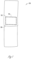
- FIGS. 1 , 1A , and 5 illustrate a damage or fall indicator coupled to a fall protection harness before any damage has occurred to the fall protection harness
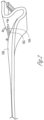
- FIGS. 2 , 3 , and 5 illustrate a damage or fall indicator coupled to a fall protection harness after damage has occurred to the fall protection harness. More specifically, these figures illustrate a strap 100 of a fall protection harness. The strap is folded over on itself and attached via threading or other means of attachment, thereby forming a first surface 130 and a second opposing surface 140. See FIG. 1A .
- the threading consists in part of electrically conducting threading 162 and electrically non-conducting threading 164.
- the electrically conducting threading 162 and the electrically non-conducting threading 164 are sewn in a hook-on pattern, and this hook-on pattern is positioned at the folded over portion of the harness 168 ( See FIG. 1 ).
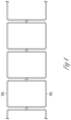
- FIG. 4 illustrates an example of the hook-on pattern, wherein the electrically conducting thread 162 is intertwined with the electrically non-conducting thread 164.
- the electrically conducting thread is intertwined with itself.
- the electrically conducting thread is not intertwined at all.
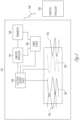
- the electrically conducting thread 162 is coupled to an electrical sensing device 510, a computer processor 515, a transmitter 520, and a power source 525.
- the transmitter 520 can transmit a signal 540, which includes an alarm or other data, to a second processor 530, which can be a smart phone and/or a computer server and computer database.
- the electrical non-conducting threading 164 Upon a fall or other damage event to the fall protection harness, the electrical non-conducting threading 164 exerts a force on the electrically conducting threading 162, causing damage to or a break in the electrically conducting thread 162, as illustrated in FIGS. 2 , 3 , and 5 .
- This damage or break is sensed by the electrical sensing device 510 as a change in voltage, current, or resistance.
- the stitching pattern such as the aforementioned hook-on pattern, can detect a single break in the conductive thread 162 and/or other damage to the conductive thread 162.
- the conductive thread 162 is an uninsulated electrically conductive material such as a stainless steel fiber or a silver coated nylon thread, which is particularly positioned in the folded-over area of the strap of the fall protection harness. Absent the hook-on pattern, the conductive thread 162 could possibly short at various points, thereby causing a break at a far end of the conductive thread 162 not to be detected. However, a unique attribute of the hook-on pattern is that a single break anywhere along the length of the conductive thread 162 will result in a detectable change in voltage, resistance, current, or a combination thereof.
- the computer processor 515 causes the transmitter 520 to generate an alarm signal to illuminate a visual alarm, sound an acoustic alarm, and/or transmit RF alarm signals 540.
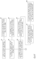
- FIGS. 6A and 6B are a block diagram illustrating a process for manufacturing a fall and damage indicator for a fall protection harness, and also features of a damage and fall indicator for a fall protection harness.
- FIGS. 6A and 6B include a number of blocks 610 - 667. Though arranged substantially serially in the example of FIGS. 6A and 6B , other examples may reorder the blocks, omit one or more blocks, and/or execute two or more blocks in parallel using multiple processors or a single processor organized as two or more virtual machines or sub-processors. Moreover, still other examples can implement the blocks as one or more specific interconnected hardware or integrated circuit modules with related control and data signals communicated between and through the modules. Thus, any process flow is applicable to software, firmware, hardware, and hybrid implementations.
- the process starts at 610 with a supply of electrically non-conductive thread and electrically conductive thread.
- the electrically non-conducting thread and the electrically conducting thread can be received from a spool or a bobbin.
- the electrically non-conductive thread and the electrically conductive thread are intertwined together. This intertwining of the electrically non-conductive thread and the electrically conductive thread can be in a hook-on pattern ( 622 ). As noted above, the hook-on pattern is illustrated in FIG. 4 .
- the intertwined electrically non-conductive thread and the electrically conductive thread are coupled to a fall protection harness.
- the coupling of the electrically non-conductive thread and the electrically conductive thread can be at a folded-over portion of the fall protection harness.
- the electrically non-conducting thread and the electrically conducting thread are applied onto an existing (or completely manufactured) fall protection harness ( 634 ).
- the electrically non-conducting thread and the electrically conducting thread are incorporated into the straps of the fall protection harness while the straps are being manufactured.
- the electrically conductive thread is coupled to an electrical sensing device, a computer processor, a transmitter, and a power source, which is further illustrated in FIG. 5 .
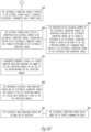
- Block 650 illustrates that the electrical sensing device detects a disruption in an electrical current in the electrically conducting thread, a disruption in voltage in the electrically conductive thread, or a change in resistance in the electrically conducting thread. This detection of a disruption or a change indicates damage to the fall protection harness or a fall by a person wearing the fall protection harness. As indicated at 652, the disruption in the electrical current in the electrically conducting thread, the disruption in voltage in the electrically conducting thread, or the change in resistance in the electrically conducting thread is caused by an aging of the fall protection harness or a damaging force applied to the electrically conducting thread by the electrically non-conducting thread.
- a transmitter transmits a signal to a second computer processor indicating one or more of the damage to the fall protection harness or the fall by the person wearing the fall protection harness.
- the second computer processor can be a smart phone, a computer server, or any other type of computing device.
- the intertwined electrically non-conductive thread and the electrically conductive thread are coupled to the fall protection harness at a folded over portion on a strap of the fall protection harness.
- the electrically non-conducting thread can be made out of polyester, and as noted at 667, the electrically conducting thread can be made out of any metal such as copper, aluminum, silver, gold, titanium, silver coated on nylon, stainless steel, or combination of several electrically conductive materials.
Landscapes
- Business, Economics & Management (AREA)
- Emergency Management (AREA)
- Health & Medical Sciences (AREA)
- General Health & Medical Sciences (AREA)
- Physics & Mathematics (AREA)
- General Physics & Mathematics (AREA)
- Emergency Lowering Means (AREA)
Description
- The present disclosure relates to fall protection harnesses and fall protection static lines, and in an embodiment, but not by way of limitation, a fall protection harness and fall protection static line with a damage indicator.
- Fall protection harnesses and fall protection static lines are critical pieces of safety equipment that are integral to preventing accidents on a job site. Fall protection harnesses provide a reliable restraint system worn by a worker that is connected to a fixed anchor point on a supporting structure, such as a building under construction. Fall protection harnesses are designed to arrest a fall of a worker quickly and safely. However, when a fall occurs, the fall protection harness causes a worker to be suspended in the fall protection harness in a potentially dangerous predicament. If there is no ladder or scaffolding for the worker to climb back onto, the worker will remain suspended until additional help can arrive. Being suspended in the fall protection harness for an extended period of time can lead to serious injury or death.
US2012/050036 discloses a safety harness includes at least one of integrally formed electrical conductors or optical conductors, which can be energized by a replaceable electrical supply. Consequently, a rapid response is crucial to the safety of the worker. Also, a fall protection harness can be damaged or compromised when a fall occurs, or damaged or compromised as the fall protection harness ages. Such damage and/or compromising caused by a fall or aging should be brought to the attention of the proper person or authority, and the fall protection harness should be inspected and/or retired from use. -
-
FIGS. 1 and1A illustrate a damage indicator coupled to a fall protection harness before any damage has occurred to the fall protection harness. -
FIG. 2 illustrates a damage indicator coupled to a fall protection harness while damage is occurring to the fall protection harness. -
FIG. 3 illustrates a damage indicator coupled to a fall protection harness after damage has occurred to the fall protection harness. -
FIG. 4 illustrates a threaded hook-on pattern for use as a damage indicator on a fall protection harness. -
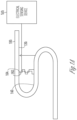
FIG. 5 illustrates a damage indicator for a fall protection harness including threaded indicator, electrical sensing device, computer processor, transmitter, and a second processor. -
FIGS. 6A and6B illustrate a process of manufacturing a fall protection harness with a damage indicator. - The invention is set out in accordance with the appended claims. In the following description, reference is made to the accompanying drawings that form a part hereof, and in which is shown by way of illustration specific embodiments which may be practiced. These embodiments are described in sufficient detail to enable those skilled in the art to practice the invention, and it is to be understood that other embodiments may be utilized and that structural, electrical, and optical changes may be made without departing from the scope of the present invention. The following description of example embodiments is, therefore, not to be taken in a limited sense, and the scope of the present invention is defined by the appended claims.
- An embodiment includes a sensor that is integrated into or attached to a fall protection harness and/or a fall protection static line. The sensor is capable of automatically sensing damage to the fall protection harness, aging of the fall protection harness, and/or a fall by a person wearing the fall protection harness. When damage or aging is sensed, the fall protection harness can be examined to determine if it is still fit for further use. When a fall is detected, a responsible person can be immediately notified of the fall event so that the person in the harness can be assisted, and thereafter the fall protection harness can be examined for damaged and/or retired from use. Notifying a responsible person of a fall event reduces the response time for help to arrive and consequently reduces the amount of time the person is suspended in the fall protection harness.
- In an embodiment, a fall protection harness is constructed of a nylon strap. At key locations on the harness, the nylon strap is folded over and attached (e.g., by sewing) onto itself to create a first portion of a damage or fall indicator. A second portion of the damage or fall indicator is a combination of an electrically conducting thread and an electrically non-conducting thread (the combination is for ease of thread breaking as nylon thread has more strength than the conductive thread and provides better isolation and separation when the conductive thread is broken) that is sewn into the fall protection harness. The electrically conducting thread is coupled to an electrical sensing device. In an embodiment, the electrically conducting thread and the electrically non-conducting thread are sewn into the fall protection harness at the folded over portion of the fall protection harness. When a worker falls from a height, the electrically non-conducting thread causes damage to and/or a break in the electrically conducting thread, which is sensed by the electrical sensing device, and causes a computer processor and transmitter to sound an alarm and/or transmit a signal that reports the fall to a proper authority so that the worker can be assisted and/or the fall protection harness can be inspected. The damage or fall alarm may consist of visual, acoustic, and radio frequency (RF) signals being emitted that will be detected by persons and equipment in the vicinity. In the case of damage to the fall protection harness that is not caused by a fall (such as a scraping of the harness against a rock or building structure), the proper authorities are still alerted that the fall protection harness could be damaged and should be inspected. In response to a fall by a person wearing a fall protection harness, rapidly alerting persons in the vicinity of the fall ensures rapid extraction of the fallen worker, thereby minimizing further injury and death.
-
FIGS. 1 ,1A , and5 illustrate a damage or fall indicator coupled to a fall protection harness before any damage has occurred to the fall protection harness, andFIGS. 2 ,3 , and5 illustrate a damage or fall indicator coupled to a fall protection harness after damage has occurred to the fall protection harness. More specifically, these figures illustrate astrap 100 of a fall protection harness. The strap is folded over on itself and attached via threading or other means of attachment, thereby forming afirst surface 130 and a secondopposing surface 140. SeeFIG. 1A . The threading consists in part of electrically conducting threading 162 and electricallynon-conducting threading 164. In an embodiment, the electrically conducting threading 162 and the electricallynon-conducting threading 164 are sewn in a hook-on pattern, and this hook-on pattern is positioned at the folded over portion of the harness 168 (SeeFIG. 1 ).FIG. 4 illustrates an example of the hook-on pattern, wherein the electrically conductingthread 162 is intertwined with the electricallynon-conducting thread 164. In another embodiment, the electrically conducting thread is intertwined with itself. In yet another embodiment, the electrically conducting thread is not intertwined at all. As illustrated inFIG. 5 , the electrically conductingthread 162 is coupled to anelectrical sensing device 510, acomputer processor 515, atransmitter 520, and apower source 525. Thetransmitter 520 can transmit asignal 540, which includes an alarm or other data, to asecond processor 530, which can be a smart phone and/or a computer server and computer database. - Upon a fall or other damage event to the fall protection harness, the
electrical non-conducting threading 164 exerts a force on the electrically conducting threading 162, causing damage to or a break in the electrically conductingthread 162, as illustrated inFIGS. 2 ,3 , and5 . This damage or break is sensed by theelectrical sensing device 510 as a change in voltage, current, or resistance. The stitching pattern, such as the aforementioned hook-on pattern, can detect a single break in theconductive thread 162 and/or other damage to theconductive thread 162. In an embodiment, theconductive thread 162 is an uninsulated electrically conductive material such as a stainless steel fiber or a silver coated nylon thread, which is particularly positioned in the folded-over area of the strap of the fall protection harness. Absent the hook-on pattern, theconductive thread 162 could possibly short at various points, thereby causing a break at a far end of theconductive thread 162 not to be detected. However, a unique attribute of the hook-on pattern is that a single break anywhere along the length of theconductive thread 162 will result in a detectable change in voltage, resistance, current, or a combination thereof. Once a damage or fall condition is confirmed by thecomputer processor 515, thecomputer processor 515 causes thetransmitter 520 to generate an alarm signal to illuminate a visual alarm, sound an acoustic alarm, and/or transmitRF alarm signals 540. -
FIGS. 6A and6B are a block diagram illustrating a process for manufacturing a fall and damage indicator for a fall protection harness, and also features of a damage and fall indicator for a fall protection harness.FIGS. 6A and6B include a number of blocks 610 - 667. Though arranged substantially serially in the example ofFIGS. 6A and6B , other examples may reorder the blocks, omit one or more blocks, and/or execute two or more blocks in parallel using multiple processors or a single processor organized as two or more virtual machines or sub-processors. Moreover, still other examples can implement the blocks as one or more specific interconnected hardware or integrated circuit modules with related control and data signals communicated between and through the modules. Thus, any process flow is applicable to software, firmware, hardware, and hybrid implementations. - Referring to
FIGS. 6A and6B , the process starts at 610 with a supply of electrically non-conductive thread and electrically conductive thread. As indicated as 612, the electrically non-conducting thread and the electrically conducting thread can be received from a spool or a bobbin. At 620, the electrically non-conductive thread and the electrically conductive thread are intertwined together. This intertwining of the electrically non-conductive thread and the electrically conductive thread can be in a hook-on pattern (622). As noted above, the hook-on pattern is illustrated inFIG. 4 . At 630, the intertwined electrically non-conductive thread and the electrically conductive thread are coupled to a fall protection harness. As also noted above, an example of such a coupling is illustrated inFIG. 1 . At 632, the coupling of the electrically non-conductive thread and the electrically conductive thread can be at a folded-over portion of the fall protection harness. In one embodiment, the electrically non-conducting thread and the electrically conducting thread are applied onto an existing (or completely manufactured) fall protection harness (634). In another embodiment, the electrically non-conducting thread and the electrically conducting thread are incorporated into the straps of the fall protection harness while the straps are being manufactured. At 640, the electrically conductive thread is coupled to an electrical sensing device, a computer processor, a transmitter, and a power source, which is further illustrated inFIG. 5 . -
Block 650 illustrates that the electrical sensing device detects a disruption in an electrical current in the electrically conducting thread, a disruption in voltage in the electrically conductive thread, or a change in resistance in the electrically conducting thread. This detection of a disruption or a change indicates damage to the fall protection harness or a fall by a person wearing the fall protection harness. As indicated at 652, the disruption in the electrical current in the electrically conducting thread, the disruption in voltage in the electrically conducting thread, or the change in resistance in the electrically conducting thread is caused by an aging of the fall protection harness or a damaging force applied to the electrically conducting thread by the electrically non-conducting thread. At 655, a transmitter transmits a signal to a second computer processor indicating one or more of the damage to the fall protection harness or the fall by the person wearing the fall protection harness. The second computer processor can be a smart phone, a computer server, or any other type of computing device. - As indicated at 660, and as further illustrated in
FIG. 1 , the intertwined electrically non-conductive thread and the electrically conductive thread are coupled to the fall protection harness at a folded over portion on a strap of the fall protection harness. As noted at 665, the electrically non-conducting thread can be made out of polyester, and as noted at 667, the electrically conducting thread can be made out of any metal such as copper, aluminum, silver, gold, titanium, silver coated on nylon, stainless steel, or combination of several electrically conductive materials. - It should be understood that there exist implementations of other variations and modifications of the invention and its various aspects, as may be readily apparent, for example, to those of ordinary skill in the art, and that the invention is not limited by specific embodiments described herein. Features and embodiments described above may be combined with each other in different combinations. It is therefore contemplated to cover any and all modifications, variations, combinations or equivalents that fall within the scope of the claims.
- In the foregoing description of the embodiments, various features are grouped together in a single embodiment for the purpose of streamlining the disclosure. This method of disclosure is not to be interpreted as reflecting that the claimed embodiments have more features than are expressly recited in each claim. Rather, as the following claims reflect, inventive subject matter lies in less than all features of a single disclosed embodiment. Thus the following claims are hereby incorporated into the Description of the Embodiments, with each claim standing on its own as a separate example embodiment.
Claims (9)
- A fall protection harness comprising:
one or more straps (100):an electrical sensing device (510) coupled to the one or more straps (100);a computer processor (515) coupled to the electrical sensing device (510); anda transmitter (520) coupled to the computer processor (515);wherein the one or more straps (100) comprise:an electrically non-conducting thread (164); andan electrically conducting thread (162);wherein the one or more straps (100) are folded at a folded over portion of the one or more straps (100) thereby forming a first surface (130) of the one or more straps (100) and a second opposing surface (140) of the one or more straps (100), and wherein the electrically non-conducting thread (164) and the electrically conducting thread (162) are intertwined and couple the first surface (130) of the one or more straps (100) to the second opposing surface (140) of the one or more straps (100) at the folded over portion of the one or more straps (100); andwherein the electrical sensing device (510) is operable to detect one or more of a disruption in current in the electrically conducting thread (162), a disruption in voltage in the electrically conducting thread (162), or a change in resistance in the electrically conducting thread (162), thereby indicating one or more of damage to the fall protection harness or a fall by a person wearing the fall protection harness. - The fall protection harness of claim 1, wherein the transmitter (520) is operable to transmit a signal to a second computer processor indicating one or more of the damage to the fall protection harness or the fall by the person wearing the fall protection harness.
- The fall protection harness of claim 1, wherein the electrically non-conducting thread (164) and the electrically conducting thread (162) are intertwined in a hook-on pattern.
- The fall protection harness of claim 3, wherein the hook-on pattern is positioned at a folded-over portion of the one or more straps (100).
- The fall protection harness of claim 1, wherein the fall protection harness comprises a completed manufacture, and the electrically non-conducting thread (164) and the electrically conducting thread (162) are incorporated onto the completed manufacture.
- The fall protection harness of claim 1, wherein the disruption in current in the electrically conducting thread, the disruption in voltage in the electrically conducting thread, or the change in resistance in the electrically conducting thread is caused by a damaging force applied to the electrically conducting thread (162) by the electrically non-conducting thread (164).
- A process for manufacturing a fall protection harness comprising:receiving an electrically non-conductive thread (164);receiving an electrically conductive thread (162);intertwining the electrically non-conductive thread (164) and the electrically conductive thread (162);coupling the intertwined electrically non-conductive thread (164) and the electrically conductive thread (162) to the fall protection harness, wherein a strap of the fall protection harness is folded over at a folded over portion of the strap thereby forming a first surface (130) of the strap and a second opposing surface (140) of the strap, wherein the coupling comprises coupling the intertwined electrically non-conductive thread (164) and the electrically conductive thread (162) to the fall protection harness so that the intertwined electrically non-conductive thread (164) and the electrically conductive thread (162) couple the first surface (130) of the strap on the fall protection harness and to the second opposing surface (140) of the strap on the fall protection harness at the folded over portion of the strap on the fall protection harness (630); andcoupling the electrically conductive thread (162) to an electrical sensing device (510), a computer processor (515), a transmitter (520), and a power source (525).
- The process of claim 7, wherein the electrically non-conducting thread (164) and the electrically conducting thread (162) are intertwined into a hook-on pattern.
- The process of claim 7, comprising configuring the electrical sensing device (510) to detect one or more of a disruption in current in the electrically conducting thread (162), a disruption in voltage in the electrically conducting thread (162), or a change in resistance in the electrically conducting thread (162), thereby indicating one or more of damage to the fall protection harness or a fall by a person wearing the fall protection harness.
Applications Claiming Priority (1)
| Application Number | Priority Date | Filing Date | Title |
|---|---|---|---|
| US15/012,437 US9799197B2 (en) | 2016-02-01 | 2016-02-01 | Fall protection harness with damage indicator |
Publications (2)
| Publication Number | Publication Date |
|---|---|
| EP3199205A1 EP3199205A1 (en) | 2017-08-02 |
| EP3199205B1 true EP3199205B1 (en) | 2023-08-16 |
Family
ID=57906490
Family Applications (1)
| Application Number | Title | Priority Date | Filing Date |
|---|---|---|---|
| EP17153064.5A Active EP3199205B1 (en) | 2016-02-01 | 2017-01-25 | Fall protection harness with damage indicator |
Country Status (2)
| Country | Link |
|---|---|
| US (1) | US9799197B2 (en) |
| EP (1) | EP3199205B1 (en) |
Families Citing this family (6)
| Publication number | Priority date | Publication date | Assignee | Title |
|---|---|---|---|---|
| JP6209400B2 (en) * | 2013-08-29 | 2017-10-04 | 矢崎総業株式会社 | Analysis apparatus and program |
| US10964133B2 (en) * | 2018-05-29 | 2021-03-30 | Zf Active Safety And Electronics Us Llc | Vehicle safety system with smart detection sensors |
| GB202001028D0 (en) * | 2020-01-24 | 2020-03-11 | Beacon Group Int Products Ltd | Fall arrest indicator |
| CN114034422B (en) * | 2021-11-25 | 2024-09-06 | 安丹达工业技术(上海)有限公司 | Safety belt falling impact indicating device |
| RU210740U1 (en) * | 2022-01-28 | 2022-04-29 | Алексей Павлович Белышев | Intelligent fall arrest personal protective equipment |
| WO2023205675A2 (en) * | 2022-04-19 | 2023-10-26 | Werner Co. | Harness for fall protection system |
Family Cites Families (28)
| Publication number | Priority date | Publication date | Assignee | Title |
|---|---|---|---|---|
| US5259833A (en) | 1992-09-15 | 1993-11-09 | Barnett Larry W | Back bending motion limiting apparatus |
| US6006860A (en) | 1993-11-10 | 1999-12-28 | Bell; Michael | Safety harness or belt with fiber means to indicate shock loading |
| US5481919A (en) | 1993-12-21 | 1996-01-09 | Brandt, Jr.; Robert O. | Force multiplying pressure transmitter diaphragm and method employing flexible force transmitting column |
| US6256789B1 (en) | 1999-04-21 | 2001-07-10 | David A. Young | Combination garment and safety harness |
| US7091932B2 (en) | 2003-07-28 | 2006-08-15 | Emerson Electric Co. | Method and apparatus for independent control of low intensity indicators used for optical communication in an appliance |
| US7319400B2 (en) | 2003-10-17 | 2008-01-15 | Bed-Check Corporation | Method and apparatus for monitoring a restraint device |
| US20080168952A1 (en) | 2004-04-01 | 2008-07-17 | Sondra Morehead | Apparatus and associated method for illuminating a collar |
| US7106205B2 (en) | 2004-09-16 | 2006-09-12 | D B Industries, Inc. | Alarm device for use with fall protection equipment |
| US20070182534A1 (en) | 2006-02-07 | 2007-08-09 | Rory Gregory | Apparatus and method for indicating seatbelt usage |
| AU2006207863B2 (en) | 2006-02-21 | 2009-05-07 | Fall Alert Industries Pty Ltd | Fall notifying apparatus |
| US20080021718A1 (en) * | 2006-06-08 | 2008-01-24 | Db Industries, Inc. | Centralized Database of Information Related to Inspection of Safety Equipment Items Inspection and Method |
| US7898674B2 (en) | 2008-06-11 | 2011-03-01 | Xerox Corporation | Apparatus and method for detecting the position of media in a media path |
| US8325053B2 (en) | 2009-03-10 | 2012-12-04 | JCJ Inc. | Personal fall protection monitoring system |
| US8348014B2 (en) * | 2009-06-26 | 2013-01-08 | Verizon Patent And Licensing Inc. | Fall-arrest ladder system |
| US8675823B2 (en) | 2009-10-30 | 2014-03-18 | Hooten Investments, Inc. | Method and apparatus for activating a communication device operably connected to a safety lanyard |
| CA2734873C (en) | 2010-03-19 | 2015-05-12 | Marlex Engineering Inc. | Radio-frequency identification (rfid) safety system |
| US8902074B2 (en) * | 2010-08-26 | 2014-12-02 | Honeywell International, Inc. | Harness for fall protection |
| WO2012044920A2 (en) | 2010-10-01 | 2012-04-05 | Honeywell International Inc. | Method and system of managing the safety of a plurality of personal protection equipment items |
| DE102011009318A1 (en) | 2011-01-25 | 2012-07-26 | Paragon Ag | Safety belt for motor vehicles, has safety belt with hose section that extends in longitudinal direction in which electrical or electronic unit of seat belt is inserted |
| US8665097B2 (en) | 2011-05-10 | 2014-03-04 | Honeywell International Inc. | System and method of worker fall detection and remote alarm notification |
| US20130056302A1 (en) | 2011-09-02 | 2013-03-07 | Honeywell International Inc. | Fall protection safety device with end of service life indicator |
| FR2984294A1 (en) | 2011-12-19 | 2013-06-21 | Haulotte Group | DEVICE FOR PROTECTING A USER OF AN ELEVATOR AND SURFACE NACELLE INCLUDING SUCH A DEVICE |
| US8898839B2 (en) | 2012-04-20 | 2014-12-02 | Evacusled Inc. | Evacuation sled |
| KR102090143B1 (en) * | 2012-11-09 | 2020-03-17 | 푸에르스트 그룹, 아이엔씨 | Footwear article having cord structure |
| ITTO20130484A1 (en) | 2013-06-12 | 2014-12-13 | Grivel Srl | ELECTRONIC DEVICE INVOLVABLE TO THE BODY OF A USER AND METHOD TO DETECT THE WEAR OF A FALL PROTECTION DEVICE |
| US9477858B2 (en) | 2013-09-27 | 2016-10-25 | The Boeing Company | Restraining system including near field RFID detection |
| US9511245B2 (en) | 2014-03-28 | 2016-12-06 | International Business Machines Corporation | Safety harness monitoring and alerting system |
| US9327678B1 (en) | 2015-03-18 | 2016-05-03 | Honda Motor Co., Ltd. | Methods and apparatus for restraining vehicular passengers with assembly including feedback sensor |
-
2016
- 2016-02-01 US US15/012,437 patent/US9799197B2/en active Active
-
2017
- 2017-01-25 EP EP17153064.5A patent/EP3199205B1/en active Active
Also Published As
| Publication number | Publication date |
|---|---|
| US20170221338A1 (en) | 2017-08-03 |
| EP3199205A1 (en) | 2017-08-02 |
| US9799197B2 (en) | 2017-10-24 |
Similar Documents
| Publication | Publication Date | Title |
|---|---|---|
| EP3199205B1 (en) | Fall protection harness with damage indicator | |
| US11024153B2 (en) | Fall detection alert/alarm device and method | |
| US10161226B2 (en) | Safety protection apparatus for personnel on oil drilling derricks | |
| EP2914350B1 (en) | Safety equipment | |
| US8928482B2 (en) | Personal fall protection system monitoring | |
| US8902074B2 (en) | Harness for fall protection | |
| EP3178528B1 (en) | Fall protection harness with damage indicator | |
| US20200282244A1 (en) | Safety harness, safety equipment comprising said harness and protection method | |
| EP3178527B1 (en) | Fall protection harness with damage indicator | |
| GB2039683A (en) | Security system | |
| US20180141627A1 (en) | Systems and methods for handling a man overboard situation | |
| US20120176243A1 (en) | Cable, sheath, and systems | |
| US7714743B1 (en) | Aircraft lightning strike detector | |
| WO2021210374A1 (en) | Safety band hook attachment/detachment confirmation system | |
| CN106253200A (en) | The method of the zone selective interlock in distribution system and monitoring distribution system | |
| EP2896961A1 (en) | De-lamination indicator | |
| JP2007265128A (en) | Abnormality alarming and monitoring system having function that prevents accidents due to wrong alarm | |
| KR101964110B1 (en) | Temperature monitoring system for terminal box | |
| CN212460727U (en) | Safety device for commodity anti-theft | |
| KR20110003842A (en) | System for preventing fire from heavy equipment |
Legal Events
| Date | Code | Title | Description |
|---|---|---|---|
| PUAI | Public reference made under article 153(3) epc to a published international application that has entered the european phase |
Free format text: ORIGINAL CODE: 0009012 |
|
| STAA | Information on the status of an ep patent application or granted ep patent |
Free format text: STATUS: REQUEST FOR EXAMINATION WAS MADE |
|
| 17P | Request for examination filed |
Effective date: 20170125 |
|
| AK | Designated contracting states |
Kind code of ref document: A1 Designated state(s): AL AT BE BG CH CY CZ DE DK EE ES FI FR GB GR HR HU IE IS IT LI LT LU LV MC MK MT NL NO PL PT RO RS SE SI SK SM TR |
|
| AX | Request for extension of the european patent |
Extension state: BA ME |
|
| STAA | Information on the status of an ep patent application or granted ep patent |
Free format text: STATUS: EXAMINATION IS IN PROGRESS |
|
| 17Q | First examination report despatched |
Effective date: 20210521 |
|
| STAA | Information on the status of an ep patent application or granted ep patent |
Free format text: STATUS: EXAMINATION IS IN PROGRESS |
|
| GRAP | Despatch of communication of intention to grant a patent |
Free format text: ORIGINAL CODE: EPIDOSNIGR1 |
|
| STAA | Information on the status of an ep patent application or granted ep patent |
Free format text: STATUS: GRANT OF PATENT IS INTENDED |
|
| INTG | Intention to grant announced |
Effective date: 20230317 |
|
| GRAS | Grant fee paid |
Free format text: ORIGINAL CODE: EPIDOSNIGR3 |
|
| GRAA | (expected) grant |
Free format text: ORIGINAL CODE: 0009210 |
|
| STAA | Information on the status of an ep patent application or granted ep patent |
Free format text: STATUS: THE PATENT HAS BEEN GRANTED |
|
| AK | Designated contracting states |
Kind code of ref document: B1 Designated state(s): AL AT BE BG CH CY CZ DE DK EE ES FI FR GB GR HR HU IE IS IT LI LT LU LV MC MK MT NL NO PL PT RO RS SE SI SK SM TR |
|
| REG | Reference to a national code |
Ref country code: GB Ref legal event code: FG4D |
|
| REG | Reference to a national code |
Ref country code: CH Ref legal event code: EP |
|
| REG | Reference to a national code |
Ref country code: DE Ref legal event code: R096 Ref document number: 602017072708 Country of ref document: DE |
|
| REG | Reference to a national code |
Ref country code: IE Ref legal event code: FG4D |
|
| REG | Reference to a national code |
Ref country code: LT Ref legal event code: MG9D |
|
| REG | Reference to a national code |
Ref country code: NL Ref legal event code: MP Effective date: 20230816 |
|
| REG | Reference to a national code |
Ref country code: AT Ref legal event code: MK05 Ref document number: 1599454 Country of ref document: AT Kind code of ref document: T Effective date: 20230816 |
|
| PG25 | Lapsed in a contracting state [announced via postgrant information from national office to epo] |
Ref country code: GR Free format text: LAPSE BECAUSE OF FAILURE TO SUBMIT A TRANSLATION OF THE DESCRIPTION OR TO PAY THE FEE WITHIN THE PRESCRIBED TIME-LIMIT Effective date: 20231117 |
|
| PG25 | Lapsed in a contracting state [announced via postgrant information from national office to epo] |
Ref country code: IS Free format text: LAPSE BECAUSE OF FAILURE TO SUBMIT A TRANSLATION OF THE DESCRIPTION OR TO PAY THE FEE WITHIN THE PRESCRIBED TIME-LIMIT Effective date: 20231216 |
|
| PG25 | Lapsed in a contracting state [announced via postgrant information from national office to epo] |
Ref country code: SE Free format text: LAPSE BECAUSE OF FAILURE TO SUBMIT A TRANSLATION OF THE DESCRIPTION OR TO PAY THE FEE WITHIN THE PRESCRIBED TIME-LIMIT Effective date: 20230816 Ref country code: RS Free format text: LAPSE BECAUSE OF FAILURE TO SUBMIT A TRANSLATION OF THE DESCRIPTION OR TO PAY THE FEE WITHIN THE PRESCRIBED TIME-LIMIT Effective date: 20230816 Ref country code: PT Free format text: LAPSE BECAUSE OF FAILURE TO SUBMIT A TRANSLATION OF THE DESCRIPTION OR TO PAY THE FEE WITHIN THE PRESCRIBED TIME-LIMIT Effective date: 20231218 Ref country code: NO Free format text: LAPSE BECAUSE OF FAILURE TO SUBMIT A TRANSLATION OF THE DESCRIPTION OR TO PAY THE FEE WITHIN THE PRESCRIBED TIME-LIMIT Effective date: 20231116 Ref country code: NL Free format text: LAPSE BECAUSE OF FAILURE TO SUBMIT A TRANSLATION OF THE DESCRIPTION OR TO PAY THE FEE WITHIN THE PRESCRIBED TIME-LIMIT Effective date: 20230816 Ref country code: LV Free format text: LAPSE BECAUSE OF FAILURE TO SUBMIT A TRANSLATION OF THE DESCRIPTION OR TO PAY THE FEE WITHIN THE PRESCRIBED TIME-LIMIT Effective date: 20230816 Ref country code: LT Free format text: LAPSE BECAUSE OF FAILURE TO SUBMIT A TRANSLATION OF THE DESCRIPTION OR TO PAY THE FEE WITHIN THE PRESCRIBED TIME-LIMIT Effective date: 20230816 Ref country code: IS Free format text: LAPSE BECAUSE OF FAILURE TO SUBMIT A TRANSLATION OF THE DESCRIPTION OR TO PAY THE FEE WITHIN THE PRESCRIBED TIME-LIMIT Effective date: 20231216 Ref country code: HR Free format text: LAPSE BECAUSE OF FAILURE TO SUBMIT A TRANSLATION OF THE DESCRIPTION OR TO PAY THE FEE WITHIN THE PRESCRIBED TIME-LIMIT Effective date: 20230816 Ref country code: GR Free format text: LAPSE BECAUSE OF FAILURE TO SUBMIT A TRANSLATION OF THE DESCRIPTION OR TO PAY THE FEE WITHIN THE PRESCRIBED TIME-LIMIT Effective date: 20231117 Ref country code: FI Free format text: LAPSE BECAUSE OF FAILURE TO SUBMIT A TRANSLATION OF THE DESCRIPTION OR TO PAY THE FEE WITHIN THE PRESCRIBED TIME-LIMIT Effective date: 20230816 Ref country code: AT Free format text: LAPSE BECAUSE OF FAILURE TO SUBMIT A TRANSLATION OF THE DESCRIPTION OR TO PAY THE FEE WITHIN THE PRESCRIBED TIME-LIMIT Effective date: 20230816 |
|
| PG25 | Lapsed in a contracting state [announced via postgrant information from national office to epo] |
Ref country code: PL Free format text: LAPSE BECAUSE OF FAILURE TO SUBMIT A TRANSLATION OF THE DESCRIPTION OR TO PAY THE FEE WITHIN THE PRESCRIBED TIME-LIMIT Effective date: 20230816 |
|
| PG25 | Lapsed in a contracting state [announced via postgrant information from national office to epo] |
Ref country code: ES Free format text: LAPSE BECAUSE OF FAILURE TO SUBMIT A TRANSLATION OF THE DESCRIPTION OR TO PAY THE FEE WITHIN THE PRESCRIBED TIME-LIMIT Effective date: 20230816 |
|
| PG25 | Lapsed in a contracting state [announced via postgrant information from national office to epo] |
Ref country code: SM Free format text: LAPSE BECAUSE OF FAILURE TO SUBMIT A TRANSLATION OF THE DESCRIPTION OR TO PAY THE FEE WITHIN THE PRESCRIBED TIME-LIMIT Effective date: 20230816 Ref country code: RO Free format text: LAPSE BECAUSE OF FAILURE TO SUBMIT A TRANSLATION OF THE DESCRIPTION OR TO PAY THE FEE WITHIN THE PRESCRIBED TIME-LIMIT Effective date: 20230816 Ref country code: ES Free format text: LAPSE BECAUSE OF FAILURE TO SUBMIT A TRANSLATION OF THE DESCRIPTION OR TO PAY THE FEE WITHIN THE PRESCRIBED TIME-LIMIT Effective date: 20230816 Ref country code: EE Free format text: LAPSE BECAUSE OF FAILURE TO SUBMIT A TRANSLATION OF THE DESCRIPTION OR TO PAY THE FEE WITHIN THE PRESCRIBED TIME-LIMIT Effective date: 20230816 Ref country code: DK Free format text: LAPSE BECAUSE OF FAILURE TO SUBMIT A TRANSLATION OF THE DESCRIPTION OR TO PAY THE FEE WITHIN THE PRESCRIBED TIME-LIMIT Effective date: 20230816 Ref country code: CZ Free format text: LAPSE BECAUSE OF FAILURE TO SUBMIT A TRANSLATION OF THE DESCRIPTION OR TO PAY THE FEE WITHIN THE PRESCRIBED TIME-LIMIT Effective date: 20230816 Ref country code: SK Free format text: LAPSE BECAUSE OF FAILURE TO SUBMIT A TRANSLATION OF THE DESCRIPTION OR TO PAY THE FEE WITHIN THE PRESCRIBED TIME-LIMIT Effective date: 20230816 |
|
| PGFP | Annual fee paid to national office [announced via postgrant information from national office to epo] |
Ref country code: DE Payment date: 20240129 Year of fee payment: 8 Ref country code: GB Payment date: 20240123 Year of fee payment: 8 |
|
| REG | Reference to a national code |
Ref country code: DE Ref legal event code: R097 Ref document number: 602017072708 Country of ref document: DE |
|
| PGFP | Annual fee paid to national office [announced via postgrant information from national office to epo] |
Ref country code: FR Payment date: 20240125 Year of fee payment: 8 |
|
| PLBE | No opposition filed within time limit |
Free format text: ORIGINAL CODE: 0009261 |
|
| STAA | Information on the status of an ep patent application or granted ep patent |
Free format text: STATUS: NO OPPOSITION FILED WITHIN TIME LIMIT |
|
| 26N | No opposition filed |
Effective date: 20240517 |
|
| PG25 | Lapsed in a contracting state [announced via postgrant information from national office to epo] |
Ref country code: IT Free format text: LAPSE BECAUSE OF FAILURE TO SUBMIT A TRANSLATION OF THE DESCRIPTION OR TO PAY THE FEE WITHIN THE PRESCRIBED TIME-LIMIT Effective date: 20230816 Ref country code: SI Free format text: LAPSE BECAUSE OF FAILURE TO SUBMIT A TRANSLATION OF THE DESCRIPTION OR TO PAY THE FEE WITHIN THE PRESCRIBED TIME-LIMIT Effective date: 20230816 |
|
| PG25 | Lapsed in a contracting state [announced via postgrant information from national office to epo] |
Ref country code: MC Free format text: LAPSE BECAUSE OF FAILURE TO SUBMIT A TRANSLATION OF THE DESCRIPTION OR TO PAY THE FEE WITHIN THE PRESCRIBED TIME-LIMIT Effective date: 20230816 |
|
| PG25 | Lapsed in a contracting state [announced via postgrant information from national office to epo] |
Ref country code: MC Free format text: LAPSE BECAUSE OF FAILURE TO SUBMIT A TRANSLATION OF THE DESCRIPTION OR TO PAY THE FEE WITHIN THE PRESCRIBED TIME-LIMIT Effective date: 20230816 |
|
| REG | Reference to a national code |
Ref country code: CH Ref legal event code: PL |
|
| PG25 | Lapsed in a contracting state [announced via postgrant information from national office to epo] |
Ref country code: LU Free format text: LAPSE BECAUSE OF NON-PAYMENT OF DUE FEES Effective date: 20240125 |