EP4477253A2 - Blutpumpe mit verbesserter leckagesteuerung und verfahren zur herstellung davon - Google Patents
Blutpumpe mit verbesserter leckagesteuerung und verfahren zur herstellung davon Download PDFInfo
- Publication number
- EP4477253A2 EP4477253A2 EP24210676.3A EP24210676A EP4477253A2 EP 4477253 A2 EP4477253 A2 EP 4477253A2 EP 24210676 A EP24210676 A EP 24210676A EP 4477253 A2 EP4477253 A2 EP 4477253A2
- Authority
- EP
- European Patent Office
- Prior art keywords
- coil
- epoxy
- primer
- yoke
- sleeve
- Prior art date
- Legal status (The legal status is an assumption and is not a legal conclusion. Google has not performed a legal analysis and makes no representation as to the accuracy of the status listed.)
- Pending
Links
Images





Classifications
-
- A—HUMAN NECESSITIES
- A61—MEDICAL OR VETERINARY SCIENCE; HYGIENE
- A61M—DEVICES FOR INTRODUCING MEDIA INTO, OR ONTO, THE BODY; DEVICES FOR TRANSDUCING BODY MEDIA OR FOR TAKING MEDIA FROM THE BODY; DEVICES FOR PRODUCING OR ENDING SLEEP OR STUPOR
- A61M60/00—Blood pumps; Devices for mechanical circulatory actuation; Balloon pumps for circulatory assistance
- A61M60/40—Details relating to driving
- A61M60/403—Details relating to driving for non-positive displacement blood pumps
- A61M60/408—Details relating to driving for non-positive displacement blood pumps the force acting on the blood contacting member being mechanical, e.g. transmitted by a shaft or cable
- A61M60/411—Details relating to driving for non-positive displacement blood pumps the force acting on the blood contacting member being mechanical, e.g. transmitted by a shaft or cable generated by an electromotor
-
- A—HUMAN NECESSITIES
- A61—MEDICAL OR VETERINARY SCIENCE; HYGIENE
- A61M—DEVICES FOR INTRODUCING MEDIA INTO, OR ONTO, THE BODY; DEVICES FOR TRANSDUCING BODY MEDIA OR FOR TAKING MEDIA FROM THE BODY; DEVICES FOR PRODUCING OR ENDING SLEEP OR STUPOR
- A61M60/00—Blood pumps; Devices for mechanical circulatory actuation; Balloon pumps for circulatory assistance
- A61M60/10—Location thereof with respect to the patient's body
- A61M60/122—Implantable pumps or pumping devices, i.e. the blood being pumped inside the patient's body
- A61M60/126—Implantable pumps or pumping devices, i.e. the blood being pumped inside the patient's body implantable via, into, inside, in line, branching on, or around a blood vessel
- A61M60/13—Implantable pumps or pumping devices, i.e. the blood being pumped inside the patient's body implantable via, into, inside, in line, branching on, or around a blood vessel by means of a catheter allowing explantation, e.g. catheter pumps temporarily introduced via the vascular system
-
- A—HUMAN NECESSITIES
- A61—MEDICAL OR VETERINARY SCIENCE; HYGIENE
- A61M—DEVICES FOR INTRODUCING MEDIA INTO, OR ONTO, THE BODY; DEVICES FOR TRANSDUCING BODY MEDIA OR FOR TAKING MEDIA FROM THE BODY; DEVICES FOR PRODUCING OR ENDING SLEEP OR STUPOR
- A61M60/00—Blood pumps; Devices for mechanical circulatory actuation; Balloon pumps for circulatory assistance
- A61M60/10—Location thereof with respect to the patient's body
- A61M60/122—Implantable pumps or pumping devices, i.e. the blood being pumped inside the patient's body
- A61M60/126—Implantable pumps or pumping devices, i.e. the blood being pumped inside the patient's body implantable via, into, inside, in line, branching on, or around a blood vessel
- A61M60/135—Implantable pumps or pumping devices, i.e. the blood being pumped inside the patient's body implantable via, into, inside, in line, branching on, or around a blood vessel inside a blood vessel, e.g. using grafting
-
- A—HUMAN NECESSITIES
- A61—MEDICAL OR VETERINARY SCIENCE; HYGIENE
- A61M—DEVICES FOR INTRODUCING MEDIA INTO, OR ONTO, THE BODY; DEVICES FOR TRANSDUCING BODY MEDIA OR FOR TAKING MEDIA FROM THE BODY; DEVICES FOR PRODUCING OR ENDING SLEEP OR STUPOR
- A61M60/00—Blood pumps; Devices for mechanical circulatory actuation; Balloon pumps for circulatory assistance
- A61M60/20—Type thereof
- A61M60/205—Non-positive displacement blood pumps
- A61M60/216—Non-positive displacement blood pumps including a rotating member acting on the blood, e.g. impeller
- A61M60/221—Non-positive displacement blood pumps including a rotating member acting on the blood, e.g. impeller the blood flow through the rotating member having both radial and axial components, e.g. mixed flow pumps
-
- A—HUMAN NECESSITIES
- A61—MEDICAL OR VETERINARY SCIENCE; HYGIENE
- A61M—DEVICES FOR INTRODUCING MEDIA INTO, OR ONTO, THE BODY; DEVICES FOR TRANSDUCING BODY MEDIA OR FOR TAKING MEDIA FROM THE BODY; DEVICES FOR PRODUCING OR ENDING SLEEP OR STUPOR
- A61M60/00—Blood pumps; Devices for mechanical circulatory actuation; Balloon pumps for circulatory assistance
- A61M60/40—Details relating to driving
- A61M60/403—Details relating to driving for non-positive displacement blood pumps
- A61M60/422—Details relating to driving for non-positive displacement blood pumps the force acting on the blood contacting member being electromagnetic, e.g. using canned motor pumps
-
- A—HUMAN NECESSITIES
- A61—MEDICAL OR VETERINARY SCIENCE; HYGIENE
- A61M—DEVICES FOR INTRODUCING MEDIA INTO, OR ONTO, THE BODY; DEVICES FOR TRANSDUCING BODY MEDIA OR FOR TAKING MEDIA FROM THE BODY; DEVICES FOR PRODUCING OR ENDING SLEEP OR STUPOR
- A61M60/00—Blood pumps; Devices for mechanical circulatory actuation; Balloon pumps for circulatory assistance
- A61M60/80—Constructional details other than related to driving
- A61M60/802—Constructional details other than related to driving of non-positive displacement blood pumps
- A61M60/804—Impellers
- A61M60/806—Vanes or blades
-
- A—HUMAN NECESSITIES
- A61—MEDICAL OR VETERINARY SCIENCE; HYGIENE
- A61M—DEVICES FOR INTRODUCING MEDIA INTO, OR ONTO, THE BODY; DEVICES FOR TRANSDUCING BODY MEDIA OR FOR TAKING MEDIA FROM THE BODY; DEVICES FOR PRODUCING OR ENDING SLEEP OR STUPOR
- A61M60/00—Blood pumps; Devices for mechanical circulatory actuation; Balloon pumps for circulatory assistance
- A61M60/80—Constructional details other than related to driving
- A61M60/802—Constructional details other than related to driving of non-positive displacement blood pumps
- A61M60/827—Sealings between moving parts
- A61M60/829—Sealings between moving parts having a purge fluid supply
-
- A—HUMAN NECESSITIES
- A61—MEDICAL OR VETERINARY SCIENCE; HYGIENE
- A61M—DEVICES FOR INTRODUCING MEDIA INTO, OR ONTO, THE BODY; DEVICES FOR TRANSDUCING BODY MEDIA OR FOR TAKING MEDIA FROM THE BODY; DEVICES FOR PRODUCING OR ENDING SLEEP OR STUPOR
- A61M60/00—Blood pumps; Devices for mechanical circulatory actuation; Balloon pumps for circulatory assistance
- A61M60/90—Details not provided for in groups A61M60/40, A61M60/50 or A61M60/80
-
- F—MECHANICAL ENGINEERING; LIGHTING; HEATING; WEAPONS; BLASTING
- F04—POSITIVE - DISPLACEMENT MACHINES FOR LIQUIDS; PUMPS FOR LIQUIDS OR ELASTIC FLUIDS
- F04D—NON-POSITIVE-DISPLACEMENT PUMPS
- F04D13/00—Pumping installations or systems
- F04D13/02—Units comprising pumps and their driving means
- F04D13/06—Units comprising pumps and their driving means the pump being electrically driven
-
- F—MECHANICAL ENGINEERING; LIGHTING; HEATING; WEAPONS; BLASTING
- F04—POSITIVE - DISPLACEMENT MACHINES FOR LIQUIDS; PUMPS FOR LIQUIDS OR ELASTIC FLUIDS
- F04D—NON-POSITIVE-DISPLACEMENT PUMPS
- F04D9/00—Priming; Preventing vapour lock
-
- A—HUMAN NECESSITIES
- A61—MEDICAL OR VETERINARY SCIENCE; HYGIENE
- A61M—DEVICES FOR INTRODUCING MEDIA INTO, OR ONTO, THE BODY; DEVICES FOR TRANSDUCING BODY MEDIA OR FOR TAKING MEDIA FROM THE BODY; DEVICES FOR PRODUCING OR ENDING SLEEP OR STUPOR
- A61M2205/00—General characteristics of the apparatus
- A61M2205/02—General characteristics of the apparatus characterised by a particular materials
- A61M2205/0238—General characteristics of the apparatus characterised by a particular materials the material being a coating or protective layer
-
- A—HUMAN NECESSITIES
- A61—MEDICAL OR VETERINARY SCIENCE; HYGIENE
- A61M—DEVICES FOR INTRODUCING MEDIA INTO, OR ONTO, THE BODY; DEVICES FOR TRANSDUCING BODY MEDIA OR FOR TAKING MEDIA FROM THE BODY; DEVICES FOR PRODUCING OR ENDING SLEEP OR STUPOR
- A61M2207/00—Methods of manufacture, assembly or production
Definitions
- This invention relates to a blood pump, in particular an intravascular blood pump, to support a blood flow in a patient's blood vessel.
- Blood pumps of different types are known, such as axial blood pumps, centrifugal blood pumps, or mixed-type blood pumps, where the blood flow is caused by both axial and radial forces.
- Intravascular blood pumps are inserted into a patient's vessel such as the aorta by means of a catheter.
- a blood pump typically comprises a pump casing having a blood flow inlet and a blood flow outlet.
- an impeller or rotor is rotatably supported with the pump casing about an axis of rotation, with the impeller being provided with on or more impeller blades for conveying blood.
- a blood pump is described in US Patent Publication No. 2018/0228953 to Seiss et al.
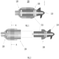
- the motor 100 of a blood pump is illustrated in FIG. 1 .
- the impeller has a drive unit 111 and impeller blades 110 are on the distal end 126 of the motor 100.
- the motor 100 has a stator 120 and a rotor 130.
- the skilled person is aware that rotary systems typically have a stator (the stationary portion) and a rotor (the rotating portion).
- FIG. 2 illustrates the motor of FIG. 1 in an exploded view with the rotor 130 outside the stator 120.
- FIG. 3 is an exploded view of the stator.
- the stator has a yoke 121, a coil 122, and a coil holding sleeve 123.
- the yoke 121 is typically made of metal, while the coil 122 is typically made of copper.
- the coil holding sleeve 123 can be either plastic or ceramic. These components are illustrated in an exploded view in FIG. 3 .
- the coil holding sleeve 123 in FIG. 3 is made of ceramic.
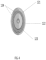
- FIG. 4 is a cross section of the stator of FIG. 2 and also illustrates the yoke 121, the coil 122 and the coil holding sleeve 123.
- the stator is assembled using epoxy adhesive 124 to provide a stable and secure assembly.
- the epoxy 124 essentially encapsulates the coil 122 such that epoxy 124 is at the yoke 121/coil 122 interface and the coil 122/sleeve 123 interface.
- FIG. 5 is a stator 120 cross section that illustrates the windings that form the coils 123.
- the stator has epoxy 124 interposed between the metal yoke 121 and the coil 122 and between the coil 122 and the sleeve 123.
- the sleeve 123 illustrated in FIG. 5 is a plastic sleeve.
- US Patent Publication No. 20180280598 which is entitled Thermistor Imbedded [sic] Therapeutic Catheter, describes an intracardiac blood pump that includes an electrically driven motor, a rotor positioned within the blood pump (for example in the cannula), and an electrical line configured to supply current to the motor.
- the motor is implanted with the rotor.
- the pump is described as powered by an external motor with a drive cable that extends through the catheter and out to a drive unit located external to the patient.
- US Patent Publication No. 20180280598 is incorporated by reference herein.
- US Patent Publication describes a blood pump that has a thermistor with a temperature sensitive head.
- the temperature sensitive head is described as being embedded in epoxy.
- US Patent No. 5,089,016 describes an implantable blood pump with a toroidal chamber coated with epoxy (e.g. Stycast Epoxy 1267).
- the pump motor has a rotor portion having proximal and distal ends and a stator portion having proximal and distal ends, wherein the proximal portion of the rotor portion is received into a cavity defined by the stator portion at the distal end of the stator portion.
- the rotor portion has an impeller, wherein the impeller comprises impeller blades and a drive unit.
- the impeller blades are positioned at the distal end of the rotor portion and not received into the stator.
- the drive unit is positioned in a portion of the rotor received into the stator portion.
- the drive unit is coupled to the impeller blades.
- the stator portion has a yoke, a coil and a coil holding sleeve. The sleeve defines the cavity into which the proximal portion of the rotor is received.
- the yoke, coil and sleeve have interior and exterior surfaces, wherein epoxy is introduced between the yoke and the coil and the coil and the sleeve, thereby substantially embedding the coil in epoxy, wherein at least one of the interior surface of the yoke, the exterior surface of the coil, the interior surface of the coil or the exterior surface of the sleeve are treated with a primer prior to the introduction of epoxy therebetween.
- the pump motor is made by assembling a pump motor from a rotor portion with proximal and distal ends and a stator portion having proximal and distal ends.
- the proximal portion of the rotor portion is received into a cavity defined by the stator portion.
- the rotor portion has an impeller, wherein the impeller has impeller blades and a drive unit.
- the impeller blades are positioned at the distal end of the rotor portion and are not received into the stator.
- the drive unit is positioned in a portion of the rotor received into the stator portion.
- the drive unit is coupled to the impeller blades.
- the stator portion has a yoke, a coil and a coil holding sleeve, the sleeve defining the cavity into which the proximal portion of the rotor is received.
- the yoke, coil and sleeve have interior and exterior surfaces. According to the method, least one of the interior surface of the yoke, the exterior surface of the coil, the interior surface of the coil or the exterior surface of the sleeve are treated with a primer. After the one or more surfaces are treated, epoxy is introduced between the yoke and the coil and the coil and the sleeve, thereby substantially embedding the coil in epoxy.
- LC Leakage Current
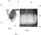
- Moisture ingress can occur at the interface between the epoxy and sleeve (such moisture ingress illustrated in FIG. 6A ) and between the epoxy and the yoke (such moisture ingress illustrated in FIG. 6B ).
- the stator of such blood pumps have a coil 122 that is essentially embedded in epoxy. The epoxy encapsulates the coil and fills the cavity to form the stator body.
- Suitable epoxies for assembling the stator described herein are well known to those skilled in the art and not described in detail herein.
- suitable epoxies are an amine base two-part epoxy such as Delo-Duopox, which is obtained from DELO Industrial Adhesives and EPO-TEK ® 301 from Epoxy Technology, Inc. of Billerica, MA.
- Suitable epoxies for use in blood pumps are well known to those skilled in the art and are not described in detail herein.
- FIG. 6A illustrates moisture ingression evidence on a coil 122, the moisture ingression from the distal end 126 ( FIG. 2 ) of the stator 120. The moisture is indicated by the shaded areas 125.
- FIG. 6B illustrates evidence of moisture ingression 125 on the epoxy 124 adjacent the yoke 121, a portion of which is removed to reveal that the epoxy had not adhered well thereto.
- the method and device described herein increases the bonding strength between the yoke and the epoxy by improving the wettability of the substrate surface (i.e. the surface to which the epoxy is intended to adhere) by the uncured epoxy.
- the increased bonding strength prevents moisture ingress. Moisture ingress indicates poor adhesion between the sleeve (either ceramic or plastic) and the epoxy. Bonding to ceramic sleeves (e.g. alumina toughened zirconia (ATZ)) in particular is difficult due to the topology of ceramic surfaces.
- ATZ alumina toughened zirconia
- the epoxy is applied in multiple locations.
- the epoxy encapsulates the coils to isolate and insulate the coils from the components adjacent to the coils that could otherwise contact the coils.
- the epoxy also fills the spaces/voids between the sleeve, the coil and the yoke, thereby providing structural strength to the assembled blood pump and avoiding/preventing/mitigating micromovement of the assembled blood that might otherwise occur as the external environment of the pump changes.
- the epoxy also facilitates the heat transfer from the coils to outside the pump.
- the gaps between the sleeve, coils and the yoke into which the epoxy is introduced are very small. Such gaps are typically about one micron.
- the pump component e.g. coil, sleeve, yoke, etc.
- a higher wettability surface causes the epoxy to spread evenly and completely fill the small gaps between the pump components.
- the improved surface wettability for the uncured epoxy results in a higher bonding strength of the epoxy to the adjacent component and excellent encapsulation of components such as the coil.
- the substrate i.e.
- the component surface) wettability is low or the surface is not otherwise compatible with the uncured epoxy, the uncured epoxy flows away from the substrate surface.
- a low bonding strength between the epoxy and the substrate, or gaps between the substrate and the epoxy, or both, will occur.
- the low bonding strength or the gaps between the epoxy and the substrate allow paths to form at the interface between the cured epoxy and the surface of the adjacent pump component through which moisture can travel. Also, gaps function as a heat insulator, which adversely affects the efficiency of heat transfer from the coils to the pump exterior. As a result, the amount of heat dissipated from the coil can be dramatically reduced.
- Disclosed herein is an apparatus and method that describes a simple substrate surface treatment that will improve surface-wettability of the substrate to which the epoxy will adhere, improving both the bonding strength of the epoxy to the substrate and the extent of the bonding between the epoxy and the substrate surface.
- a primer-treated ceramic surface 210 i.e. the sleeve
- a non-treated ceramic surface 200 is illustrated.
- the isolated shaded regions 201 i.e. the beaded regions
- the fluid 201 forms on the surface 200 as liquid beads leaving a substantial area of the substrate surface 200 uncovered by the liquid.
- the surface 210 is more substantially covered by the liquid 211, indicating that surface 210 is more compatible with the liquid.
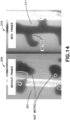
- the liquid 211 is more uniformly spread around the surface 211 and, as a consequence of the increased substrate surface wetting, there will be increased bonding strength between the substrate surface and the cured epoxy.
- FIG. 14 illustrates that the primer-treated surface described herein enhances the quality of the bond between the epoxy and the substrate.
- the primers described herein not only improve wettability of the substrate to the uncured epoxy, but also modify the substrate surfaces that are otherwise hydrophilic and make those surfaces hydrophobic. The resulting hydrophobic surfaces resist moisture ingress into any remaining gaps between the epoxy and the substrate.
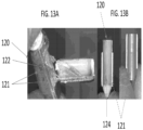
- FIG. 13A illustrates a stator 120 in which a portion of the yoke 121 is separated from the stator 120.
- the stator 120 in FIG. 13A had epoxy 124 treated with a silane solution.
- Silane solutions are known primers that function at the interface between the uncured epoxy and act as an adhesion promoter.
- the silane primer is chosen by matching its organic functionality to the polymer to optimize bonding.
- Silane coupling agents contain two types of reactivity, inorganic and organic, in the same molecule.
- Silane have the general chemical formula (RO) 3 SiCH 2 CH 2 CH 2 -X wherein RO is a hydrolysable group such as methoxy, ethoxy, or acetoxy and X in an organofunctional group such as amino, methacryloxy, epoxy, etc.
- RO is a hydrolysable group such as methoxy, ethoxy, or acetoxy and X in an organofunctional group such as amino, methacryloxy, epoxy, etc.
- the alkoxy groups hydrolyze and the resulting hydroxyl groups bond to the hydroxyl groups on the inorganic substrate surfaces (e.g., the metal, metal oxide and ceramic surfaces described herein.
- the epoxy adheres strongly to the primed surface of the yoke 121 such that the epoxy and even a portion of the coil 122 is torn away with the portion of the yoke 121 separated from the stator 120.
- the surface treatment is performed prior to the stator being injection molded. Basically, here is a brief flow: 1). the coil is attached to the sleeve; 2). wires and cables are soldered to a printed circuit board (PCB) which is then adhered to the ceramic sleeve; 3).
- PCB printed circuit board
- the yoke inner diameter (ID) is treated with primer ( FIG. 9 ); 4).
- the sleeve/coil outer diameter (OD) is then treated with primer ( FIGs. 10 and 11 ); 5).
- the yoke is installed over the sleeve/coil subassembly; and 6). epoxy is injected into the assembly .
- FIGs. 12 and 13B did not have primer applied to the interior surface of the yoke 121. This is apparent since the portion of the yoke 121 that is separated from the stator 120 has no epoxy 124 thereon. This illustrates that there was little to no bonding of the epoxy 124 to the yoke 121 in the stator 120 illustrated in 13B .
- FIG. 6B also illustrates a stator 120 in which the epoxy 124 did not adhere to the portion of the yoke 121 removed from the stator.
- the shaded epoxy region 124 indicates moisture ingress, demonstrating that, due to the poor adhesion between the epoxy 124 and the yoke 121, moisture was able to migrate into the interface between the yoke 121 and the epoxy 124. Contrast the stator in 13B with that in FIG. 13A , where the bonding surface was treated as described herein. The yoke 121 was significantly damaged when a portion of the yoke 121 was separated from the stator 120.
- the primer also improves the bond between the sleeve 123 and the epoxy 124. Just as the epoxy 124 remains adhered to the portion of the yoke 121 separated from the stator 120, at least a portion of the epoxy will remain adhered to the sleeve 123 during a tear down process in which the sleeve (or a portion thereof) is separated from the stator 120.
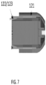
- FIG. 7A highlights the interface 129 between the yoke 121 and the coil/sleeve 122/123.
- the stator 120 has a silane treated surface on the interior of the yoke 121, the exterior of the coil 122 and exterior of the sleeve 123.
- the silane treated surface is 128 in FIG. 8B .
- the coil is not visible because it is embedded in the epoxy 124.
- a silane primer is provided to improve the bonding between the epoxy and the yoke and or the sleeve.
- Application of silane primer eliminated the leakage current by improving the adhesion between ceramic sleeve and the epoxy (e.g., EPO-TEK ® 301 ( ES2019-181 rA ).
- FIG. 15 illustrates that pumps in which the primer was applied to the surface of at least some of the pump components prior to the introduction of epoxy had consistently lower leakage current. Pumps that were assembled without the application of the primer prior to epoxy injection had a range of leakage current results. Therefore, the application of the primer to the surface of the pump components provides the assembled pumps with reliable and acceptable performance regarding leakage current.
- wetting of the bonding surfaces as well as chemical bond formation with the bonding surface provides better adhesion between two different surfaces (e.g. the epoxy and the yoke surface or the sleeve surface.
- the primers described herein are silane-based primers. Such primers improve the wetting of epoxies such as EPO-TEK ® 301 on the surface of the ceramic sleeve or the metal yoke for better adhesion.
- the silane forms a chemical bond with the substrate surface and with the epoxy that improves the adhesion strength between the epoxy and the substrate (e.g. the metal yoke/ceramic sleeve of the pump.
- Silane based primers that act as coupling agent between the relevant pump component and the adjacent epoxy that are both hydrophobic and organophilic are contemplated as suitable herein.
Landscapes
- Health & Medical Sciences (AREA)
- Engineering & Computer Science (AREA)
- Heart & Thoracic Surgery (AREA)
- Mechanical Engineering (AREA)
- Anesthesiology (AREA)
- Public Health (AREA)
- Veterinary Medicine (AREA)
- Cardiology (AREA)
- General Health & Medical Sciences (AREA)
- Biomedical Technology (AREA)
- Hematology (AREA)
- Life Sciences & Earth Sciences (AREA)
- Animal Behavior & Ethology (AREA)
- Vascular Medicine (AREA)
- General Engineering & Computer Science (AREA)
- Transplantation (AREA)
- External Artificial Organs (AREA)
- Structures Of Non-Positive Displacement Pumps (AREA)
Applications Claiming Priority (3)
| Application Number | Priority Date | Filing Date | Title |
|---|---|---|---|
| US202062959552P | 2020-01-10 | 2020-01-10 | |
| PCT/US2021/070013 WO2021142490A1 (en) | 2020-01-10 | 2021-01-08 | Blood pump with improved leakage control |
| EP21704690.3A EP4087641B1 (de) | 2020-01-10 | 2021-01-08 | Blutpumpe mit verbesserter leckkontrolle und verfahren zu seiner herstellung |
Related Parent Applications (1)
| Application Number | Title | Priority Date | Filing Date |
|---|---|---|---|
| EP21704690.3A Division EP4087641B1 (de) | 2020-01-10 | 2021-01-08 | Blutpumpe mit verbesserter leckkontrolle und verfahren zu seiner herstellung |
Publications (2)
| Publication Number | Publication Date |
|---|---|
| EP4477253A2 true EP4477253A2 (de) | 2024-12-18 |
| EP4477253A3 EP4477253A3 (de) | 2025-02-19 |
Family
ID=74587157
Family Applications (2)
| Application Number | Title | Priority Date | Filing Date |
|---|---|---|---|
| EP21704690.3A Active EP4087641B1 (de) | 2020-01-10 | 2021-01-08 | Blutpumpe mit verbesserter leckkontrolle und verfahren zu seiner herstellung |
| EP24210676.3A Pending EP4477253A3 (de) | 2020-01-10 | 2021-01-08 | Blutpumpe mit verbesserter leckagesteuerung und verfahren zur herstellung davon |
Family Applications Before (1)
| Application Number | Title | Priority Date | Filing Date |
|---|---|---|---|
| EP21704690.3A Active EP4087641B1 (de) | 2020-01-10 | 2021-01-08 | Blutpumpe mit verbesserter leckkontrolle und verfahren zu seiner herstellung |
Country Status (13)
| Country | Link |
|---|---|
| US (3) | US20210213274A1 (de) |
| EP (2) | EP4087641B1 (de) |
| JP (1) | JP2023510780A (de) |
| KR (1) | KR20220124250A (de) |
| CN (1) | CN114929326A (de) |
| AU (1) | AU2021205985A1 (de) |
| CA (1) | CA3162782A1 (de) |
| DE (1) | DE112021000501T5 (de) |
| DK (1) | DK4087641T3 (de) |
| ES (1) | ES3000114T3 (de) |
| IL (2) | IL294353B2 (de) |
| TW (1) | TWI884202B (de) |
| WO (1) | WO2021142490A1 (de) |
Families Citing this family (12)
| Publication number | Priority date | Publication date | Assignee | Title |
|---|---|---|---|---|
| DE102018207594A1 (de) | 2018-05-16 | 2019-11-21 | Kardion Gmbh | Rotor, Magnetkupplungsvorrichtung, Elektromotor für ein Herzunterstützungssystem, Pumpeneinheit für ein Herzunterstützungssystem sowie Verfahren zum Herstellen eines Rotors |
| DE102018208539A1 (de) | 2018-05-30 | 2019-12-05 | Kardion Gmbh | Motorgehäusemodul zum Abdichten eines Motorraums eines Motors eines Herzunterstützungssystems und Herzunterstützungssystem und Verfahren zum Montieren eines Herzunterstützungssystems |
| DE102018208549A1 (de) | 2018-05-30 | 2019-12-05 | Kardion Gmbh | Elektronikmodul für ein Herzunterstützungssystem und Verfahren zum Herstellen eines Elektronikmoduls für ein Herzunterstützungssystem |
| DE102018210058A1 (de) | 2018-06-21 | 2019-12-24 | Kardion Gmbh | Statorschaufelvorrichtung zur Strömungsführung eines aus einer Austrittsöffnung eines Herzunterstützungssystems ausströmenden Fluids, Herzunterstützungssystem mit Statorschaufelvorrichtung, Verfahren zum Betreiben einer Statorschaufelvorrichtung und Herstellverfahren |
| DE102018211297A1 (de) | 2018-07-09 | 2020-01-09 | Kardion Gmbh | Herzunterstützungssystem und Verfahren zur Überwachung der Integrität einer Haltestruktur eines Herzunterstützungssystems |
| DE102018211328A1 (de) | 2018-07-10 | 2020-01-16 | Kardion Gmbh | Laufradgehäuse für ein implantierbares, vaskuläres Unterstützungssystem |
| DE102018211327A1 (de) | 2018-07-10 | 2020-01-16 | Kardion Gmbh | Laufrad für ein implantierbares, vaskuläres Unterstützungssystem |
| DE102020102474A1 (de) | 2020-01-31 | 2021-08-05 | Kardion Gmbh | Pumpe zum Fördern eines Fluids und Verfahren zum Herstellen einer Pumpe |
| CA3192451A1 (en) | 2020-09-14 | 2022-03-17 | Johannes Bette | Cardiovascular support pump having an impeller with a variable flow area |
| JP2023550938A (ja) | 2020-11-20 | 2023-12-06 | カルディオン ゲーエムベーハー | ガイドワイヤ補助具付き機械的循環支持システム |
| CN115720015A (zh) * | 2022-12-10 | 2023-02-28 | 安徽通灵仿生科技有限公司 | 一种空心杯马达及其导管泵 |
| CN116914972B (zh) * | 2023-08-03 | 2025-10-21 | 安徽通灵仿生科技有限公司 | 空心杯电机、制作方法及其导管泵 |
Citations (7)
| Publication number | Priority date | Publication date | Assignee | Title |
|---|---|---|---|---|
| US5089016A (en) | 1989-06-15 | 1992-02-18 | Abiomed Cardiovascular, Inc. | Blood pump |
| US5911685A (en) | 1996-04-03 | 1999-06-15 | Guidant Corporation | Method and apparatus for cardiac blood flow assistance |
| US6794789B2 (en) | 2000-11-25 | 2004-09-21 | Impella Cardiosystems Ag | Miniature motor |
| US9402942B2 (en) | 2010-12-01 | 2016-08-02 | Abiomed, Inc. | Loading guide lumen |
| US9872948B2 (en) | 2003-08-08 | 2018-01-23 | Abiomed Europe Gmbh | Intracardiac pumping device |
| US20180228953A1 (en) | 2015-08-04 | 2018-08-16 | Abiomed Europe Gmbh | Blood pump |
| US20180280598A1 (en) | 2017-03-21 | 2018-10-04 | Abiomed, Inc. | Thermistor imbedded therapeutic catheter |
Family Cites Families (12)
| Publication number | Priority date | Publication date | Assignee | Title |
|---|---|---|---|---|
| ES2019181A6 (es) | 1989-11-14 | 1991-06-01 | Parker William P | Dispositivo de presentacion de descarga en gas. |
| US5924975A (en) * | 1995-08-30 | 1999-07-20 | International Business Machines Corporation | Linear pump |
| US6245007B1 (en) * | 1999-01-28 | 2001-06-12 | Terumo Cardiovascular Systems Corporation | Blood pump |
| DE29921352U1 (de) * | 1999-12-04 | 2001-04-12 | Impella Cardiotechnik AG, 52074 Aachen | Intravasale Blutpumpe |
| US6887308B2 (en) * | 2003-01-21 | 2005-05-03 | Johnsondiversey, Inc. | Metal coating coupling composition |
| JP2008035605A (ja) * | 2006-07-28 | 2008-02-14 | Nippon Densan Corp | モータの製造方法およびモータ |
| JP2014121222A (ja) * | 2012-12-19 | 2014-06-30 | Panasonic Corp | レジンモールド構造体 |
| US9616158B2 (en) * | 2013-12-04 | 2017-04-11 | Heartware, Inc. | Molded VAD |
| US10590232B2 (en) * | 2016-06-02 | 2020-03-17 | Hitachi Chemical Company, Ltd. | Resin composition and method of producing laminate |
| EP3319098A1 (de) * | 2016-11-02 | 2018-05-09 | Abiomed Europe GmbH | Intravaskuläre blutpumpe mit korrosionsbeständigem dauermagneten |
| EP3542835A1 (de) * | 2018-03-23 | 2019-09-25 | Abiomed Europe GmbH | Verfahren zur herstellung einer blutpumpe |
| DK3567619T3 (da) * | 2018-05-08 | 2021-01-04 | Abiomed Europe Gmbh | Korrosionsresistent permanent magnet og intravaskulær blodpumpe omfattende magneten |
-
2021
- 2021-01-08 AU AU2021205985A patent/AU2021205985A1/en active Pending
- 2021-01-08 ES ES21704690T patent/ES3000114T3/es active Active
- 2021-01-08 EP EP21704690.3A patent/EP4087641B1/de active Active
- 2021-01-08 DK DK21704690.3T patent/DK4087641T3/da active
- 2021-01-08 IL IL294353A patent/IL294353B2/en unknown
- 2021-01-08 CA CA3162782A patent/CA3162782A1/en active Pending
- 2021-01-08 JP JP2022542124A patent/JP2023510780A/ja active Pending
- 2021-01-08 TW TW110100704A patent/TWI884202B/zh active
- 2021-01-08 WO PCT/US2021/070013 patent/WO2021142490A1/en not_active Ceased
- 2021-01-08 DE DE112021000501.4T patent/DE112021000501T5/de active Pending
- 2021-01-08 CN CN202180008634.XA patent/CN114929326A/zh active Pending
- 2021-01-08 US US17/144,570 patent/US20210213274A1/en not_active Abandoned
- 2021-01-08 EP EP24210676.3A patent/EP4477253A3/de active Pending
- 2021-01-08 KR KR1020227027533A patent/KR20220124250A/ko active Pending
-
2024
- 2024-04-19 US US18/640,108 patent/US12420079B2/en active Active
-
2025
- 2025-08-29 US US19/314,018 patent/US20260077177A1/en active Pending
- 2025-09-11 IL IL323302A patent/IL323302A/en unknown
Patent Citations (7)
| Publication number | Priority date | Publication date | Assignee | Title |
|---|---|---|---|---|
| US5089016A (en) | 1989-06-15 | 1992-02-18 | Abiomed Cardiovascular, Inc. | Blood pump |
| US5911685A (en) | 1996-04-03 | 1999-06-15 | Guidant Corporation | Method and apparatus for cardiac blood flow assistance |
| US6794789B2 (en) | 2000-11-25 | 2004-09-21 | Impella Cardiosystems Ag | Miniature motor |
| US9872948B2 (en) | 2003-08-08 | 2018-01-23 | Abiomed Europe Gmbh | Intracardiac pumping device |
| US9402942B2 (en) | 2010-12-01 | 2016-08-02 | Abiomed, Inc. | Loading guide lumen |
| US20180228953A1 (en) | 2015-08-04 | 2018-08-16 | Abiomed Europe Gmbh | Blood pump |
| US20180280598A1 (en) | 2017-03-21 | 2018-10-04 | Abiomed, Inc. | Thermistor imbedded therapeutic catheter |
Also Published As
| Publication number | Publication date |
|---|---|
| DE112021000501T5 (de) | 2022-11-17 |
| IL294353A (en) | 2022-08-01 |
| EP4087641B1 (de) | 2024-11-06 |
| ES3000114T3 (en) | 2025-02-27 |
| IL294353B1 (en) | 2025-10-01 |
| US20210213274A1 (en) | 2021-07-15 |
| TW202135873A (zh) | 2021-10-01 |
| WO2021142490A1 (en) | 2021-07-15 |
| AU2021205985A1 (en) | 2022-09-01 |
| TWI884202B (zh) | 2025-05-21 |
| IL323302A (en) | 2025-11-01 |
| US12420079B2 (en) | 2025-09-23 |
| DK4087641T3 (da) | 2025-01-06 |
| EP4087641A1 (de) | 2022-11-16 |
| KR20220124250A (ko) | 2022-09-13 |
| JP2023510780A (ja) | 2023-03-15 |
| US20250090832A1 (en) | 2025-03-20 |
| CN114929326A (zh) | 2022-08-19 |
| US20260077177A1 (en) | 2026-03-19 |
| EP4477253A3 (de) | 2025-02-19 |
| CA3162782A1 (en) | 2021-07-15 |
| IL294353B2 (en) | 2026-02-01 |
Similar Documents
| Publication | Publication Date | Title |
|---|---|---|
| US12420079B2 (en) | Blood pump with improved leakage control | |
| US12383724B2 (en) | Method of manufacturing a blood pump | |
| AU772374B2 (en) | Intravascular blood pump | |
| EP3542835A1 (de) | Verfahren zur herstellung einer blutpumpe | |
| HK40113953A (en) | Blood pump with improved leakage control and method for producing the same | |
| HK40082513A (en) | Blood pump with improved leakage control and method for producing the same | |
| HK40082513B (en) | Blood pump with improved leakage control and method for producing the same | |
| US20240285933A1 (en) | Cannula with dip coated inner polymer | |
| HK40090413A (en) | Method of manufacturing a blood pump | |
| CN117728597A (zh) | 驱动机构及其血泵 | |
| HK40108757A (en) | Intravascular blood pump with ceramic inner sleeve | |
| HK40041760B (en) | Method of manufacturing a blood pump | |
| HK40041760A (en) | Method of manufacturing a blood pump |
Legal Events
| Date | Code | Title | Description |
|---|---|---|---|
| PUAI | Public reference made under article 153(3) epc to a published international application that has entered the european phase |
Free format text: ORIGINAL CODE: 0009012 |
|
| STAA | Information on the status of an ep patent application or granted ep patent |
Free format text: STATUS: THE APPLICATION HAS BEEN PUBLISHED |
|
| AC | Divisional application: reference to earlier application |
Ref document number: 4087641 Country of ref document: EP Kind code of ref document: P |
|
| AK | Designated contracting states |
Kind code of ref document: A2 Designated state(s): AL AT BE BG CH CY CZ DE DK EE ES FI FR GB GR HR HU IE IS IT LI LT LU LV MC MK MT NL NO PL PT RO RS SE SI SK SM TR |
|
| REG | Reference to a national code |
Ref country code: DE Ref legal event code: R079 Free format text: PREVIOUS MAIN CLASS: A61M0060810000 Ipc: A61M0060117000 |
|
| PUAL | Search report despatched |
Free format text: ORIGINAL CODE: 0009013 |
|
| AK | Designated contracting states |
Kind code of ref document: A3 Designated state(s): AL AT BE BG CH CY CZ DE DK EE ES FI FR GB GR HR HU IE IS IT LI LT LU LV MC MK MT NL NO PL PT RO RS SE SI SK SM TR |
|
| RIC1 | Information provided on ipc code assigned before grant |
Ipc: A61M 60/81 20210101ALI20250113BHEP Ipc: A61M 60/422 20210101ALI20250113BHEP Ipc: A61M 60/216 20210101ALI20250113BHEP Ipc: A61M 60/122 20210101ALI20250113BHEP Ipc: A61M 60/117 20210101AFI20250113BHEP |
|
| P01 | Opt-out of the competence of the unified patent court (upc) registered |
Free format text: CASE NUMBER: APP_3341/2025 Effective date: 20250121 |
|
| REG | Reference to a national code |
Ref country code: HK Ref legal event code: DE Ref document number: 40113953 Country of ref document: HK |
|
| STAA | Information on the status of an ep patent application or granted ep patent |
Free format text: STATUS: REQUEST FOR EXAMINATION WAS MADE |
|
| 17P | Request for examination filed |
Effective date: 20250807 |
|
| STAA | Information on the status of an ep patent application or granted ep patent |
Free format text: STATUS: EXAMINATION IS IN PROGRESS |