EP4477246A1 - Balloon catheter and method of manufacturing balloon catheter - Google Patents
Balloon catheter and method of manufacturing balloon catheter Download PDFInfo
- Publication number
- EP4477246A1 EP4477246A1 EP22925820.7A EP22925820A EP4477246A1 EP 4477246 A1 EP4477246 A1 EP 4477246A1 EP 22925820 A EP22925820 A EP 22925820A EP 4477246 A1 EP4477246 A1 EP 4477246A1
- Authority
- EP
- European Patent Office
- Prior art keywords
- outer layer
- layer
- tube
- balloon catheter
- inner layer
- Prior art date
- Legal status (The legal status is an assumption and is not a legal conclusion. Google has not performed a legal analysis and makes no representation as to the accuracy of the status listed.)
- Pending
Links
Images





Classifications
-
- A—HUMAN NECESSITIES
- A61—MEDICAL OR VETERINARY SCIENCE; HYGIENE
- A61M—DEVICES FOR INTRODUCING MEDIA INTO, OR ONTO, THE BODY; DEVICES FOR TRANSDUCING BODY MEDIA OR FOR TAKING MEDIA FROM THE BODY; DEVICES FOR PRODUCING OR ENDING SLEEP OR STUPOR
- A61M25/00—Catheters; Hollow probes
- A61M25/10—Balloon catheters
-
- A—HUMAN NECESSITIES
- A61—MEDICAL OR VETERINARY SCIENCE; HYGIENE
- A61M—DEVICES FOR INTRODUCING MEDIA INTO, OR ONTO, THE BODY; DEVICES FOR TRANSDUCING BODY MEDIA OR FOR TAKING MEDIA FROM THE BODY; DEVICES FOR PRODUCING OR ENDING SLEEP OR STUPOR
- A61M25/00—Catheters; Hollow probes
- A61M25/0043—Catheters; Hollow probes characterised by structural features
- A61M25/0045—Catheters; Hollow probes characterised by structural features multi-layered, e.g. coated
-
- A—HUMAN NECESSITIES
- A61—MEDICAL OR VETERINARY SCIENCE; HYGIENE
- A61M—DEVICES FOR INTRODUCING MEDIA INTO, OR ONTO, THE BODY; DEVICES FOR TRANSDUCING BODY MEDIA OR FOR TAKING MEDIA FROM THE BODY; DEVICES FOR PRODUCING OR ENDING SLEEP OR STUPOR
- A61M25/00—Catheters; Hollow probes
- A61M25/10—Balloon catheters
- A61M25/1027—Making of balloon catheters
-
- A—HUMAN NECESSITIES
- A61—MEDICAL OR VETERINARY SCIENCE; HYGIENE
- A61M—DEVICES FOR INTRODUCING MEDIA INTO, OR ONTO, THE BODY; DEVICES FOR TRANSDUCING BODY MEDIA OR FOR TAKING MEDIA FROM THE BODY; DEVICES FOR PRODUCING OR ENDING SLEEP OR STUPOR
- A61M25/00—Catheters; Hollow probes
- A61M25/10—Balloon catheters
- A61M25/1027—Making of balloon catheters
- A61M25/1029—Production methods of the balloon members, e.g. blow-moulding, extruding, deposition or by wrapping a plurality of layers of balloon material around a mandril
-
- A—HUMAN NECESSITIES
- A61—MEDICAL OR VETERINARY SCIENCE; HYGIENE
- A61M—DEVICES FOR INTRODUCING MEDIA INTO, OR ONTO, THE BODY; DEVICES FOR TRANSDUCING BODY MEDIA OR FOR TAKING MEDIA FROM THE BODY; DEVICES FOR PRODUCING OR ENDING SLEEP OR STUPOR
- A61M25/00—Catheters; Hollow probes
- A61M25/10—Balloon catheters
- A61M2025/1043—Balloon catheters with special features or adapted for special applications
- A61M2025/1075—Balloon catheters with special features or adapted for special applications having a balloon composed of several layers, e.g. by coating or embedding
Definitions
- the technique disclosed herein relates to a balloon catheter, and a method of manufacturing the balloon catheter.
- Balloon catheters are elongated medical appliances that are inserted into a body lumen such as a blood vessel to widen and expand a constricted part in the body lumen, or to restrict stream of a fluid (e.g. blood flow) by obstructing the body lumen.
- a body lumen such as a blood vessel to widen and expand a constricted part in the body lumen, or to restrict stream of a fluid (e.g. blood flow) by obstructing the body lumen.
- a balloon catheter includes an inner layer tube, an outer layer that covers an outer peripheral surface of the inner layer tube, and a balloon that covers an outer peripheral surface of the outer layer (e.g. refer to Patent Literature 1).
- An inner cavity of the inner layer tube is in communication with an inner space of the balloon to serve as an expansion medium lumen.
- an expansion medium (contrast medium, physiological saline, etc.) is fed toward the inner space of the balloon through the inner cavity of the inner layer tube as the expansion medium lumen.
- the expansion medium is discharged from the inner space of the balloon through the inner cavity of the inner layer tube as the expansion medium lumen.
- Patent Literature 1 WO 2020/075278
- a negative pressure is generated in an expansion medium lumen when the expansion medium is discharged through the expansion medium lumen to contract the balloon.
- the inner layer tube may be detached from the outer layer and crushed by the negative pressure generated in the expansion medium lumen, and the conventional balloon configurations have room for improvement in terms of smoothening discharge of the expansion medium through the expansion medium lumen.
- FIG. 1 to FIG. 3 are explanatory views illustrating a configuration of a balloon catheter 100 according to the first embodiment.
- FIG. 1 illustrates a side configuration of the balloon catheter 100
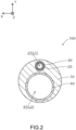
- FIG. 2 illustrates a transverse sectional configuration of the balloon catheter 100, taken along II-II in FIG. 1
- FIG. 3 illustrates a longitudinal sectional configuration of a distal end portion (X1 portion in FIG. 1 ) of the balloon catheter 100.
- illustration of a part of the balloon catheter 100 is omitted.
- the positive side in Z-axis direction is defined as the distal end side (farther side) to be inserted into a body
- the negative side in Z-axis direction is defined as the proximal end side (nearer side) to be manipulated by a professional such as a surgeon.
- the end on the distal end side is referred to as a "distal end”
- the distal end together with its vicinity is referred to as a "distal end portion”
- the end on the proximal end side is referred to as a "proximal end”
- the proximal end together with its vicinity is referred to as a "proximal end portion”.
- the balloon catheter 100 is, as a whole, in a straight line shape parallel to Z-axis direction, but is flexible enough to be curved.
- the balloon catheter 100 is an elongated medical appliance that is inserted into a body lumen such as a blood vessel to widen and expand a constricted part in the body lumen, or to restrict stream of a fluid (e.g. blood flow) by obstructing the body lumen.
- the total length of the balloon catheter 100 is e.g. about 1500 mm to 2000 mm.
- the balloon catheter 100 is a balloon guiding catheter having a device lumen L2 described later for guiding a device.
- the balloon catheter 100 is used to stop the blood flow so that pieces of the stripped thrombus do not flow through the blood vessel.
- the balloon catheter 100 includes an outer layer 10, a first inner layer tube 20, an adhesive layer 30, a second inner layer tube 40, a distal tip 50, a balloon 60, and a Y connector 80.
- the first inner layer tube 20 is a cylindrical (e.g. hollow cylindrical) member.
- the first inner layer tube 20 has an outer diameter of e.g. about 0.08 mm to 0.8 mm, and a wall thickness of e.g. about 10 ⁇ m to 80 ⁇ m.
- An inner cavity 21 of the first inner layer tube 20 serves as an expansion medium lumen L1 through which an expansion medium (contrast medium, physiological saline, etc.) for expanding the balloon 60 flows.
- the first inner layer tube 20 is an example of the inner layer tube in claims.
- the first inner layer tube 20 is made of a flexible material.
- the material for the first inner layer tube 20 include resins, more specifically polyamide, polyamide elastomer, polyester, polyurethane, polyurethane elastomer, and polyetheretherketone (PEEK).
- the transverse sectional shape of the first inner layer tube 20 (an example of the inner layer tube in claims) can be set as appropriate.
- Examples of the transverse sectional shape of the first inner layer tube 20 include a circler shape, an oval shape, and a polygonal shape.
- Examples of the polygonal shape include a square shape and a rectangular shape.
- the size along the radial direction of the oval or rectangular first inner layer tube 20 can be smaller than the size along a direction perpendicular to the radial direction.
- Such a size setting makes it possible to decrease the size along the radial direction of the first inner layer tube 20 when the area of the expansion medium lumen L1 is the same as of the first inner layer tube 20 in the transverse section of the first inner layer tube 20 (without decreasing the flow rate of the expansion medium), and therefore the balloon catheter 100 can be decreased in diameter.
- the second inner layer tube 40 is a cylindrical (e.g. hollow cylindrical) member.
- the second inner layer tube 40 has an inner diameter of e.g. about 1.5 mm to 3.0 mm, and a wall thickness of e.g. about 5 ⁇ m to 30 ⁇ m.
- An inner cavity 41 of the second inner layer tube 40 serves as the device lumen L2 through which a guide wire or various devices (e.g. suction catheter or thrombus removing catheter) are inserted.
- the second inner layer tube 40 is made of a flexible material.
- the material for the second inner layer tube 40 include resins, more specifically PTFE (polytetrafluoroethylene), PVDF (polyvinylidene fluoride), PFA (perfluoroalkoxy alkane), FEP (perfuluoroethylene propane), ETFE (ethylene/tetrafluoroethylene), polyethylene, and polypropylene.
- PTFE polytetrafluoroethylene
- PVDF polyvinylidene fluoride
- PFA perfluoroalkoxy alkane
- FEP perfuluoroethylene propane
- ETFE ethylene/tetrafluoroethylene
- polyethylene polypropylene.
- a reinforcing body formed by knitting a metal wire into a mesh shape may be arranged so as to cover the outer peripheral surface of the second inner layer tube 40.
- the outer layer 10 is a cylindrical member that covers the outer peripheral surface of the first inner layer tube 20 and the outer peripheral surface of the second inner layer tube 40.
- the phrase "the A member covers the outer peripheral surface of the B member” means that the A member is placed outside at least a part of the outer peripheral surface of the B member, and does not exclude an aspect in which another member is interposed between the A member and the outer peripheral surface of the B member.
- the outer layer 10 covers almost the entire outer peripheral surface of the first inner layer tube 20 over almost the entire length of the first inner layer tube 20, and also covers almost the entire outer peripheral surface of the second inner layer tube 40 over almost the entire length of the second inner layer tube 40.
- the outer layer 10 has an outer diameter of e.g. about 2.0 mm to 3.5 mm.
- the outer layer 10 is made of a flexible material.
- the material for the outer layer 10 include resins, more specifically polyamide, polyamide elastomer, polyester, polyurethane, and polyurethane elastomer.
- the outer layer 10 includes a first outer layer 11, and a second outer layer 12 placed on the proximal end side relative to the first outer layer 11.
- the second outer layer 12 is connected to the proximal end portion of the first outer layer 11 so as to be substantially coaxial with the first outer layer 11.
- the first outer layer 11 has a hardness lower than that of the second outer layer 12.
- the adhesive layer 30 is placed between the first inner layer tube 20 and the outer layer 10 to bond them. That means, the first inner layer tube 20 is bonded to the outer layer 10 via the adhesive layer 30.
- the material for the adhesive layer 30 include resins, more specifically urethane resins.
- the second inner layer tube 40 is directly joined to the outer layer 10 e.g. by fusion bonding.
- the distal tip 50 is a cylindrical (e.g. hollow cylindrical) member.
- the distal tip 50 is placed on the distal end side of the outer layer 10 and joined to the distal end of the outer layer 10 e.g. by fusion bonding.
- the outer diameter of the distal tip 50 is substantially equal to that of the outer layer 10.
- An inner cavity 51 of the distal tip 50 is in communication with the inner cavity 41 of the second inner layer tube 40 and serves as the device lumen L2 together with the inner cavity 41 of the second inner layer tube 40.
- Examples of the material for the distal tip 50 include resins, more specifically urethane resins.
- the balloon 60 is a hollow member having an inner space 61 and is expandable and contractable in association with feeding and discharge of the expansion medium.
- the balloon 60 covers the outer peripheral surface of the distal end portion of the outer layer 10 and the outer peripheral surface of the distal tip 50.
- the distal end portion of the balloon 60 is joined to the outer peripheral surface of the distal tip 50 e.g. by fusion bonding, and the proximal end portion of the balloon 60 is joined to the outer peripheral surface of the distal end portion of the outer layer 10 e.g. by fusion bonding.
- Examples of the material for the balloon 60 include resins and rubbers, more specifically polyolefins such as polyethylene, polypropylene, polybutene, ethylenepropylene copolymer, ethylene-vinyl acetate copolymer, ionomer, and a mixture of two or more of them; thermoplastic resins such as soft polyvinyl chloride resin, polyamide, polyamide elastomer, polyester, polyester elastomer, polyurethane, and fluororesin; silicone rubbers; and latex rubbers.
- polyolefins such as polyethylene, polypropylene, polybutene, ethylenepropylene copolymer, ethylene-vinyl acetate copolymer, ionomer, and a mixture of two or more of them
- thermoplastic resins such as soft polyvinyl chloride resin, polyamide, polyamide elastomer, polyester, polyester elastomer, polyurethane, and fluororesin
- silicone rubbers and latex rubber
- an inner space 61 of the balloon 60 and the inner cavity 21 (expansion medium lumen L1) of the first inner layer tube 20 are in communication with each other. That means, the balloon catheter 100 has a communication channel (communication hole) C1 that extends radially from the inner peripheral surface on the distal end portion of the first inner layer tube 20 to the outer peripheral surface of the outer layer 10, and the inner space 61 of the balloon 60 and the inner cavity 21 of the first inner layer tube 20 are in communication with each other through the communication channel C1.
- the Y connector 80 constitutes the proximal end portion of the balloon catheter 100.
- the Y connector 80 has an expansion medium port 81 in communication with the expansion medium lumen L1, and a device port 82 in communication with the device lumen L2.
- the expansion medium is fed to the inner space 61 of the balloon 60 from the expansion medium port 81 through the expansion medium lumen L1 and the communication channel C1.
- the expansion medium in the inner space 61 of the balloon 60 is discharged from the expansion medium port 81 through the communication channel C1 and the expansion medium lumen L1.
- the balloon catheter 100 is a so-called over-the-wire (OTW) type balloon catheter.
- OGW over-the-wire
- FIG. 4 is an explanatory diagram presenting a hardness of each member constituting the balloon catheter 100 according to the first embodiment.
- the adhesive layer 30 has a shore hardness (A) of 80
- the first outer layer 11 has a shore hardness (D) of 30
- the second outer layer 12 has a shore hardness (D) of 80
- the first inner layer tube 20 has a shore hardness (D) of 2000.
- the hardnesses of the four members are set in an ascending order of the adhesive layer 30, the first outer layer 11, the second outer layer 12, and the first inner layer tube 20.
- Such a hardness relationship can be achieved e.g. by forming the adhesive layer 30 from a urethane resin, the first outer layer 11 from a mixed material of a urethane resin and a nylon resin, the second outer layer 12 from a nylon resin, and the first inner layer tube 20 from PEEK.
- each member adheresive layer 30, first outer layer 11, second outer layer 12, and first inner layer tube 20
- the melting points of the materials for the four members are set in an ascending order of the adhesive layer 30, the first outer layer 11, the second outer layer 12, and the first inner layer tube 20.
- the adhesive layer 30 is made of a material with a melting point of 81 °C
- the first outer layer 11 is made of a material with a melting point of 170°C
- the second outer layer 12 is made of a material with a melting point of 178°C
- the first inner layer tube 20 is made of a material with a melting point of 334°C.
- the first inner layer tube 20 and the outer layer 10 cannot be fusion-bonded to each other. For this reason, the first inner layer tube 20 and the outer layer 10 are bonded to each other via the adhesive layer 30.
- the second inner layer tube 40 is made of a material capable of fusion-bonding to the outer layer 10 and is fusion-bonded with the outer layer 10.
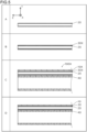
- FIG. 5 to FIG. 7 are explanatory views illustrating an example of a method of manufacturing the balloon catheter 100 according to the first embodiment.
- the first inner layer tube 20 is first prepared as illustrated in column A of FIG. 5 , and a material 30X for the adhesive layer 30 is placed on the outer peripheral surface of the first inner layer tube 20 as illustrated in column B of FIG. 5 .
- the material 30X for the adhesive layer 30 can be placed on the outer peripheral surface of the first inner layer tube 20 e.g. by extrusion coating.
- the placement of the material 30X for the adhesive layer 30 may be performed concurrently with fabrication of the first inner layer tube 20 by coextrusion.
- a precursor 100X is fabricated by covering the first inner layer tube 20 and the separately prepared second inner layer tube 40 with a material 10X for the outer layer 10.
- the outer layer 10 includes the first outer layer 11 and the second outer layer 12, and therefore the material 10X for the outer layer 10 includes the material for the first outer layer 11 and the material for the second outer layer 12.
- the precursor 100X is heated. This heating is performed at a temperature at which the material 30X for the adhesive layer 30 and the material 10X of the outer layer 10 are molten.
- the material 10X for the outer layer 10 is molten to form the outer layer 10
- the material 30X for the adhesive layer 30 is molten to form the adhesive layer 30 that is placed between the first inner layer tube 20 and the outer layer 10 to bond them, as illustrated in column D of FIG. 5 .
- the second inner layer tube 40 is fusion-bonded to the outer layer 10.
- This heating may be performed on the entire precursor 100X at once, or the precursor 100X may be divided into a portion made of the material for the first outer layer 11 and a portion made of the material for the second outer layer 12 so that these parts are sequentially subjected to the heating.
- the portion made of the material for the first outer layer 11 in the precursor 100X may be first heated, followed by heating of the portion made of the material for the second outer layer 12.
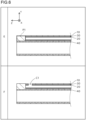
- the distal end portion of the first inner layer tube 20 (portion P1 in the figure) is removed as illustrated in column E of FIG. 6 , and the communication channel C1 that radially extends from the inner peripheral surface on the distal end portion of the first inner layer tube 20 to the outer peripheral surface of the outer layer 10 is formed e.g. by laser processing as illustrated in column F of FIG. 6 .
- the distal tip 50 is joined to the distal end of the outer layer 10 e.g. by fusion bonding as illustrated in column G of FIG. 7
- the balloon 60 is joined to the outer layer 10 and the distal tip 50 e.g. by fusion bonding as illustrated in column H of FIG. 7
- the Y connector 80 is attached to the proximal end portion of the outer layer 10.
- the manufacture method as described above makes it possible to manufacture the balloon catheter 100 configured as described above.
- the balloon catheter 100 includes the first inner layer tube 20, the outer layer 10, the balloon 60, and the adhesive layer 30.
- the outer layer 10 covers the outer peripheral surface of the first inner layer tube 20.
- the balloon 60 covers the outer peripheral surface of the outer layer 10.
- the inner space 61 of the balloon 60 and the inner cavity 21 of the first inner layer tube 20 are in communication with each other.
- the adhesive layer 30 is placed between the first inner layer tube 20 and the outer layer 10 to bond them.
- the inner cavity 21 of the first inner layer tube 20 is in communication with the inner space 61 of the balloon 60 to serve as the expansion medium lumen L1.
- the first inner layer tube 20 is bonded to the outer layer 10 via the adhesive layer 30.
- the adhesive layer 30 has a hardness lower than hardnesses of both at least a part of the outer layer 10 and at least a part of the first inner layer tube 20.
- the first inner layer tube 20 can be suitably bonded to the outer layer 10 via the adhesive layer 30. Consequently, the balloon catheter 100 according to the first embodiment makes it possible to effectively suppress detachment of the first inner layer tube 20 from the outer layer 10 and to achieve smoother discharge of the expansion medium through the expansion medium lumen L1.
- the first inner layer tube 20 has a hardness higher than that of the outer layer 10.
- the first inner layer tube 20 can be effectively prevented from being crushed. Consequently, the balloon catheter 100 according to the first embodiment makes it possible to effectively suppress crushing of the first inner layer tube 20 and to achieve smoother discharge of the expansion medium through the expansion medium lumen L1.
- the outer layer 10 includes the first outer layer 11, and the second outer layer 12 placed on the proximal end side relative to the first outer layer 11, and the first outer layer 11 has a hardness lower than that of the second outer layer 12.
- the distal end portion of the balloon catheter 100 can be made relatively softer for improving its followability for a body lumen, while the proximal end portion of the balloon catheter 100 can be made relatively harder for improving its pushability.
- the adhesive layer 30 has a hardness lower than hardnesses of all of the first outer layer 11, the second outer layer 12, and the first inner layer tube 20.
- the adhesive layer 30 can improve the bonding of the first inner layer tube 20 to both the first outer layer 11 and the second outer layer 12. Consequently, the balloon catheter 100 according to the first embodiment makes it possible to effectively suppress detachment of the inner layer tube 20 from the outer layer 10 including the first outer layer 11 and the second outer layer 12 and to achieve smoother discharge of the expansion medium through the expansion medium lumen L1.
- the first inner layer tube 20 has a hardness higher than hardnesses of both the first outer layer 11 and the second outer layer 12.
- the first inner layer tube 20 can be more effectively prevented from being crushed. Consequently, the balloon catheter 100 according to the first embodiment makes it possible to effectively suppress crushing of the first inner layer tube 20 and to achieve smoother discharge of the expansion medium through the expansion medium lumen L1.
- the method of manufacturing the balloon catheter 100 according to the first embodiment includes: a step of preparing the first inner layer tube 20 and placing the material 30X for the adhesive layer 30 on the outer peripheral surface of the first inner layer tube 20; a step of fabricating the precursor 100X by covering the first inner layer tube 20 with the material 10X for the outer layer 10; and a step of forming the outer layer 10 by heating the precursor 100X to melt the material 10X for the outer layer 10 and furthermore forming the adhesive layer 30 between the first inner layer tube 20 and the outer layer 10 by melting the material 30X for the adhesive layer 30.
- the method of manufacturing the balloon catheter 100 according to the first embodiment can facilitate the manufacture of the balloon catheter 100 with the first inner layer tube 20 bonded to the outer layer 10 via the adhesive layer 30.
- FIG. 8 is an explanatory view illustrating a side configuration of a balloon catheter 100a according to the second embodiment.
- the same components as in the balloon catheter 100 according to the first embodiment described above are marked with the same symbols as in the first embodiment, and their explanations are omitted as appropriate.
- an outer layer 10a has, in addition to the first outer layer 11 and the second outer layer 12, a third outer layer 13 placed on the distal end side relative to the first outer layer 11.
- the third outer layer 13 is connected to the distal end portion of the first outer layer 11 so as to be coaxial with the first outer layer 11.
- FIG. 9 is an explanatory diagram presenting a hardness of each member constituting the balloon catheter 100a according to the second embodiment.
- the adhesive layer 30 has a shore hardness (A) of 80
- the third outer layer 13 has a shore hardness (A) of 80
- the first outer layer 11 has a shore hardness (D) of 30
- the second outer layer 12 has a shore hardness (D) of 80
- the first inner layer tube 20 has a shore hardness (D) of 2000.
- the hardnesses of the five members are set in an ascending order of the adhesive layer 30 and the third outer layer 13, the first outer layer 11, the second outer layer 12, and the first inner layer tube 20.
- a hardness relationship can be achieved e.g. by forming the adhesive layer 30 and the third outer layer 13 from a urethane resin, the first outer layer 11 from a mixed material of a urethane resin and a nylon resin, the second outer layer 12 from a nylon resin, and the first inner layer tube 20 from PEEK.
- the balloon catheter 100a according to the second embodiment includes the first inner layer tube 20, the outer layer 10a, the balloon 60, and the adhesive layer 30, similarly to the balloon catheter 100 according to the first embodiment described above.
- the outer layer 10a covers the outer peripheral surface of the first inner layer tube 20.
- the balloon 60 covers the outer peripheral surface of the outer layer 10a.
- the inner space 61 of the balloon 60 and the inner cavity 21 of the first inner layer tube 20 are in communication with each other.
- the adhesive layer 30 is placed between the first inner layer tube 20 and the outer layer 10a to bond them.
- the first inner layer tube 20 can be prevented from being detached from the outer layer 10a and crushed if a negative pressure is generated in the expansion medium lumen L1 due to discharge of the expansion medium through the expansion medium lumen L1, decrease in the cross-sectional area of the expansion medium lumen L1 due to the detachment and crushing of the first inner layer tube 20 can be suppressed, and the expansion medium can be smoothly discharged through the expansion medium lumen L1.
- the outer layer 10a includes the third outer layer 13, the first outer layer 11 placed on the proximal end side relative to the third outer layer 13, and the second outer layer 12 placed on the proximal end side relative to the first outer layer 11, and the third outer layer 13 has a hardness lower than that of the first outer layer 11 and the first outer layer 11 has a hardness lower than that of the second outer layer 12.
- the distal end portion of the balloon catheter 100a can be made relatively softer for improving its followability for a body lumen, while the proximal end portion of the balloon catheter 100a can be made relatively harder for improving its pushability, and furthermore a stiffness gap along the length direction of the balloon catheter 100a can be reduced to improve a kink resistance.
- the configuration of the balloon catheter 100 according to the above embodiment is merely an example and can be variously modified.
- the inner space 61 of the balloon 60 and the inner cavity 21 (expansion medium lumen L1) of the first inner layer tube 20 are in communication with each other through the communication channel C1
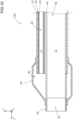
- the inner space 61 of the balloon 60 and the inner cavity 21 of the first inner layer tube 20 may be in direct contact with each other like the modification illustrated in FIG. 10 .
- the inner cavity 21 of the first inner layer tube 20 is in communication with the inner space 61 of the balloon 60 on the distal end of the first inner layer tube 20.
- the outer layer 10 includes the first outer layer 11 and the second outer layer 12 (or the first outer layer 11, the second outer layer 12, and the third outer layer 13) aligned in an extending direction and having different hardnesses
- the outer layer 10 may include four or more portions having different hardnesses, or may have a uniform hardness over the entire length.
- the outer and inner diameters of each portion of the outer layer 10 in the extending direction may be uniform or ununiform.
- the first inner layer tube 20 may include a plurality of portions aligned in the extending direction and having different hardnesses.
- the outer and inner diameters of each portion of the first inner layer tube 20 in the extending direction may be uniform or ununiform.
- each member according to the above embodiment is merely an example and can be variously modified.
- the outer layer 10, the first inner layer tube 20, the second inner layer tube 40, the distal tip 50, and other members may be made of another material (e.g. metal, carbon fiber, ceramics) instead of the resin.
- each member and the hardness level relationship therebetween in the above embodiment are merely examples and can be variously modified.
- the first outer layer 11 has the hardness lower than that of the second outer layer 12
- the first outer layer 11 may have a hardness higher than that of the second outer layer 12.
- the third outer layer 13 has a hardness lower than that of the first outer layer 11 and the first outer layer 11 has a hardness lower than that of the second outer layer 12
- the third outer layer 13 may have a hardness higher than that of the first outer layer 11 and the first outer layer 11 may have a hardness higher than that of the second outer layer 12.
- the adhesive layer 30 has a hardness lower than that of both the first outer layer 11 and second outer layer 12
- the adhesive layer 30 may have a hardness lower than that of either one of the first outer layer 11 and second outer layer 12 and equal to or higher than that of the other one.
- the adhesive layer 30 may have a hardness lower than that of either one of the first outer layer 11 and second outer layer 12 and equal to or higher than that of the other one and higher than that of the third outer layer 13.
- the method of manufacturing the balloon catheter 100 according to the above embodiment is merely an example and can be variously modified.
- the joining of the distal tip 50 is performed after the removal of the distal end portion of the first inner layer tube 20 and the formation of the communication channel C1
- the joining of the distal tip 50 may be performed before the removal of the distal end portion of the first inner layer tube 20 and the formation of the communication channel C1.
- the balloon catheter 100 is a so-called over-the-wire type balloon catheter, the technique disclosed in this specification is also applicable to a so-called rapid exchange (RX) type balloon catheter.
- the balloon catheter 100 is a balloon guiding catheter having the device lumen L2 for guiding a device, the technique disclosed in this specification is also applicable to a balloon catheter that does not have a device lumen for guiding a device other than a guide wire but has a guide wire lumen through which a guide wire is inserted.
Landscapes
- Health & Medical Sciences (AREA)
- Life Sciences & Earth Sciences (AREA)
- Heart & Thoracic Surgery (AREA)
- Engineering & Computer Science (AREA)
- Biomedical Technology (AREA)
- Pulmonology (AREA)
- Biophysics (AREA)
- Anesthesiology (AREA)
- Hematology (AREA)
- Animal Behavior & Ethology (AREA)
- General Health & Medical Sciences (AREA)
- Public Health (AREA)
- Veterinary Medicine (AREA)
- Child & Adolescent Psychology (AREA)
- Manufacturing & Machinery (AREA)
- Media Introduction/Drainage Providing Device (AREA)
Abstract
Description
- The technique disclosed herein relates to a balloon catheter, and a method of manufacturing the balloon catheter.
- Balloon catheters are elongated medical appliances that are inserted into a body lumen such as a blood vessel to widen and expand a constricted part in the body lumen, or to restrict stream of a fluid (e.g. blood flow) by obstructing the body lumen.
- A balloon catheter includes an inner layer tube, an outer layer that covers an outer peripheral surface of the inner layer tube, and a balloon that covers an outer peripheral surface of the outer layer (e.g. refer to Patent Literature 1). An inner cavity of the inner layer tube is in communication with an inner space of the balloon to serve as an expansion medium lumen. When the balloon is expanded, an expansion medium (contrast medium, physiological saline, etc.) is fed toward the inner space of the balloon through the inner cavity of the inner layer tube as the expansion medium lumen. When the balloon is contracted, the expansion medium is discharged from the inner space of the balloon through the inner cavity of the inner layer tube as the expansion medium lumen.
- Patent Literature 1:
WO 2020/075278 - In balloon catheters, a negative pressure is generated in an expansion medium lumen when the expansion medium is discharged through the expansion medium lumen to contract the balloon. In the conventional balloon catheter configurations, the inner layer tube may be detached from the outer layer and crushed by the negative pressure generated in the expansion medium lumen, and the conventional balloon configurations have room for improvement in terms of smoothening discharge of the expansion medium through the expansion medium lumen.
- In this specification, a technique capable of solving the above-described problems is disclosed.
- The technique disclosed in this specification can be achieved e.g. as the following aspects.
-
- (1) The balloon catheter disclosed in this specification includes an inner layer tube, an outer layer, a balloon, and an adhesive layer. The outer layer covers the outer peripheral surface of the inner layer tube. The balloon covers the outer peripheral surface of the outer layer. The inner space of the balloon and the inner cavity of the inner layer tube are in communication with each other. The adhesive layer is placed between the inner layer tube and the outer layer.
In this balloon catheter, the inner cavity of the inner layer tube is in communication with the inner space of the balloon to serve as an expansion medium lumen. The inner layer tube is bonded to the outer layer via the adhesive layer. Thus, if a negative pressure is generated in the expansion medium lumen due to discharge of the expansion medium through the expansion medium lumen, the inner layer tube can be prevented from being detached from the outer layer and crushed. Thus, this balloon catheter makes it possible to suppress decrease in a cross-sectional area of the expansion medium lumen due to the detachment and crushing of the inner layer tube and to achieve smooth discharge of the expansion medium through the expansion medium lumen. - (2) The balloon catheter may be configured such that the adhesive layer has a hardness lower than any of hardness of at least a part of the outer layer and hardness of at least a part of the inner layer tube. This configuration can improve the bonding between the inner layer tube and the outer layer via the adhesive layer. Thus, according to this configuration, detachment of the inner layer tube from the outer layer can be effectively suppressed, and the expansion medium can be more smoothly discharged through the expansion medium lumen.
- (3) The balloon catheter may be configured such that the inner layer tube has a hardness higher than that of the outer layer. This configuration can effectively suppress crushing of the inner layer tube if a negative pressure is generated in the expansion medium lumen. Thus, according to this configuration, crushing of the inner layer tube can be effectively suppressed, and the expansion medium can be more smoothly discharged through the expansion medium lumen.
- (4) The balloon catheter may be configured such that the outer layer includes a first outer layer and a second outer layer placed on a proximal end side relative to the first outer layer, and the first outer layer has a hardness lower than that of the second outer layer. According to this configuration, a distal end portion of the balloon catheter can be made relatively softer for improving its followability for a body lumen, while a proximal end portion of the balloon catheter can be made relatively harder for improving its pushability.
- (5) The balloon catheter may be configured such that the adhesive layer has a hardness lower than hardnesses of all of the first outer layer, the second outer layer, and the inner layer tube. According to this configuration, the adhesive layer can improve the bonding of the inner layer tube to both the first and second outer layers. Thus, according to this configuration, detachment of the inner layer tube from the outer layer including the first and second outer layers can be effectively suppressed, and the expansion medium can be more smoothly discharged through the expansion medium lumen.
- (6) The balloon catheter may be configured such that the inner layer tube has a hardness higher than hardnesses of both the first outer layer and the second outer layer. This configuration makes it possible to effectively suppress crushing of the inner layer tube if a negative pressure is generated in the expansion medium lumen. Thus, according to this configuration, the crushing of the inner layer tube can be more effectively suppressed, and the expansion medium can be more smoothly discharged through the expansion medium lumen.
- (7) In a method of manufacturing a balloon catheter disclosed in this specification, the balloon catheter includes an inner layer tube, an outer layer covering an outer peripheral surface of the inner layer tube, and a balloon covering an outer peripheral surface of the outer layer and having an inner space in communication with an inner cavity of the inner layer tube. The method includes: preparing the inner layer tube and disposing a material for an adhesive layer on an outer peripheral surface of the inner layer tube; fabricating a precursor by covering the inner layer tube with a material for the outer layer; and forming the outer layer by heating the precursor to melt the material for the outer layer and furthermore forming the adhesive layer between the inner layer tube and the outer layer by melting the material for the adhesive layer. The method of manufacturing the balloon catheter can facilitate manufacture of the balloon catheter with the inner layer tube bonded to the outer layer via the adhesive layer.
- The technique disclosed in this specification can be achieved in various aspects e.g. in aspects of a balloon catheter and a manufacture method thereof.
-
-
FIG. 1 is an explanatory view illustrating a side configuration of aballoon catheter 100 according to the first embodiment. -
FIG. 2 is an explanatory view illustrating a transverse sectional configuration of theballoon catheter 100 according to the first embodiment. -
FIG. 3 is an explanatory view illustrating a longitudinal sectional configuration of theballoon catheter 100 according to the first embodiment. -
FIG. 4 is an explanatory diagram presenting a hardness of each member constituting theballoon catheter 100 according to the first embodiment. -
FIG. 5 is an explanatory view illustrating an example of a method of manufacturing theballoon catheter 100 according to the first embodiment. -
FIG. 6 is an explanatory view illustrating an example of a method of manufacturing theballoon catheter 100 according to the first embodiment. -
FIG. 7 is an explanatory view illustrating an example of a method of manufacturing theballoon catheter 100 according to the first embodiment. -
FIG. 8 is an explanatory view illustrating a side configuration of aballoon catheter 100a according to the second embodiment. -
FIG. 9 is an explanatory diagram presenting a hardness of each member constituting theballoon catheter 100a according to the second embodiment. -
FIG. 10 is an explanatory view illustrating a longitudinal sectional configuration of theballoon catheter 100 according to a modification. -
FIG. 1 to FIG. 3 are explanatory views illustrating a configuration of aballoon catheter 100 according to the first embodiment.FIG. 1 illustrates a side configuration of theballoon catheter 100,FIG. 2 illustrates a transverse sectional configuration of theballoon catheter 100, taken along II-II inFIG. 1 , andFIG. 3 illustrates a longitudinal sectional configuration of a distal end portion (X1 portion inFIG. 1 ) of theballoon catheter 100. In some figures, illustration of a part of theballoon catheter 100 is omitted. In each figure, the positive side in Z-axis direction is defined as the distal end side (farther side) to be inserted into a body, and the negative side in Z-axis direction is defined as the proximal end side (nearer side) to be manipulated by a professional such as a surgeon. Hereinafter, in theballoon catheter 100 and its components, the end on the distal end side is referred to as a "distal end", the distal end together with its vicinity is referred to as a "distal end portion", the end on the proximal end side is referred to as a "proximal end", and the proximal end together with its vicinity is referred to as a "proximal end portion". InFIG. 1 , theballoon catheter 100 is, as a whole, in a straight line shape parallel to Z-axis direction, but is flexible enough to be curved. - The
balloon catheter 100 is an elongated medical appliance that is inserted into a body lumen such as a blood vessel to widen and expand a constricted part in the body lumen, or to restrict stream of a fluid (e.g. blood flow) by obstructing the body lumen. The total length of theballoon catheter 100 is e.g. about 1500 mm to 2000 mm. - The
balloon catheter 100 according to the first embodiment is a balloon guiding catheter having a device lumen L2 described later for guiding a device. For example, in a procedure in which a thrombus in a cerebral blood vessel is removed using a thrombus removing catheter delivered through the device lumen L2, theballoon catheter 100 is used to stop the blood flow so that pieces of the stripped thrombus do not flow through the blood vessel. - The
balloon catheter 100 includes anouter layer 10, a firstinner layer tube 20, anadhesive layer 30, a secondinner layer tube 40, adistal tip 50, aballoon 60, and aY connector 80. - The first
inner layer tube 20 is a cylindrical (e.g. hollow cylindrical) member. The firstinner layer tube 20 has an outer diameter of e.g. about 0.08 mm to 0.8 mm, and a wall thickness of e.g. about 10 µm to 80 µm. Aninner cavity 21 of the firstinner layer tube 20 serves as an expansion medium lumen L1 through which an expansion medium (contrast medium, physiological saline, etc.) for expanding theballoon 60 flows. The firstinner layer tube 20 is an example of the inner layer tube in claims. - The first
inner layer tube 20 is made of a flexible material. Examples of the material for the firstinner layer tube 20 include resins, more specifically polyamide, polyamide elastomer, polyester, polyurethane, polyurethane elastomer, and polyetheretherketone (PEEK). - The transverse sectional shape of the first inner layer tube 20 (an example of the inner layer tube in claims) can be set as appropriate. Examples of the transverse sectional shape of the first
inner layer tube 20 include a circler shape, an oval shape, and a polygonal shape. Examples of the polygonal shape include a square shape and a rectangular shape. When the transverse sectional shape of the firstinner layer tube 20 is e.g. oval or rectangular, the size along the radial direction of the oval or rectangular firstinner layer tube 20 can be smaller than the size along a direction perpendicular to the radial direction. Such a size setting makes it possible to decrease the size along the radial direction of the firstinner layer tube 20 when the area of the expansion medium lumen L1 is the same as of the firstinner layer tube 20 in the transverse section of the first inner layer tube 20 (without decreasing the flow rate of the expansion medium), and therefore theballoon catheter 100 can be decreased in diameter. - The second
inner layer tube 40 is a cylindrical (e.g. hollow cylindrical) member. The secondinner layer tube 40 has an inner diameter of e.g. about 1.5 mm to 3.0 mm, and a wall thickness of e.g. about 5 µm to 30 µm. Aninner cavity 41 of the secondinner layer tube 40 serves as the device lumen L2 through which a guide wire or various devices (e.g. suction catheter or thrombus removing catheter) are inserted. - The second
inner layer tube 40 is made of a flexible material. Examples of the material for the secondinner layer tube 40 include resins, more specifically PTFE (polytetrafluoroethylene), PVDF (polyvinylidene fluoride), PFA (perfluoroalkoxy alkane), FEP (perfuluoroethylene propane), ETFE (ethylene/tetrafluoroethylene), polyethylene, and polypropylene. For example, a reinforcing body formed by knitting a metal wire into a mesh shape may be arranged so as to cover the outer peripheral surface of the secondinner layer tube 40. - The
outer layer 10 is a cylindrical member that covers the outer peripheral surface of the firstinner layer tube 20 and the outer peripheral surface of the secondinner layer tube 40. In this specification, the phrase "the A member covers the outer peripheral surface of the B member" means that the A member is placed outside at least a part of the outer peripheral surface of the B member, and does not exclude an aspect in which another member is interposed between the A member and the outer peripheral surface of the B member. In the first embodiment, theouter layer 10 covers almost the entire outer peripheral surface of the firstinner layer tube 20 over almost the entire length of the firstinner layer tube 20, and also covers almost the entire outer peripheral surface of the secondinner layer tube 40 over almost the entire length of the secondinner layer tube 40. Theouter layer 10 has an outer diameter of e.g. about 2.0 mm to 3.5 mm. - The
outer layer 10 is made of a flexible material. Examples of the material for theouter layer 10 include resins, more specifically polyamide, polyamide elastomer, polyester, polyurethane, and polyurethane elastomer. - In the first embodiment, the
outer layer 10 includes a firstouter layer 11, and a secondouter layer 12 placed on the proximal end side relative to the firstouter layer 11. The secondouter layer 12 is connected to the proximal end portion of the firstouter layer 11 so as to be substantially coaxial with the firstouter layer 11. The firstouter layer 11 has a hardness lower than that of the secondouter layer 12. - The
adhesive layer 30 is placed between the firstinner layer tube 20 and theouter layer 10 to bond them. That means, the firstinner layer tube 20 is bonded to theouter layer 10 via theadhesive layer 30. Examples of the material for theadhesive layer 30 include resins, more specifically urethane resins. The secondinner layer tube 40 is directly joined to theouter layer 10 e.g. by fusion bonding. - The
distal tip 50 is a cylindrical (e.g. hollow cylindrical) member. Thedistal tip 50 is placed on the distal end side of theouter layer 10 and joined to the distal end of theouter layer 10 e.g. by fusion bonding. The outer diameter of thedistal tip 50 is substantially equal to that of theouter layer 10. Aninner cavity 51 of thedistal tip 50 is in communication with theinner cavity 41 of the secondinner layer tube 40 and serves as the device lumen L2 together with theinner cavity 41 of the secondinner layer tube 40. Examples of the material for thedistal tip 50 include resins, more specifically urethane resins. - The
balloon 60 is a hollow member having aninner space 61 and is expandable and contractable in association with feeding and discharge of the expansion medium. Theballoon 60 covers the outer peripheral surface of the distal end portion of theouter layer 10 and the outer peripheral surface of thedistal tip 50. The distal end portion of theballoon 60 is joined to the outer peripheral surface of thedistal tip 50 e.g. by fusion bonding, and the proximal end portion of theballoon 60 is joined to the outer peripheral surface of the distal end portion of theouter layer 10 e.g. by fusion bonding. - Examples of the material for the
balloon 60 include resins and rubbers, more specifically polyolefins such as polyethylene, polypropylene, polybutene, ethylenepropylene copolymer, ethylene-vinyl acetate copolymer, ionomer, and a mixture of two or more of them; thermoplastic resins such as soft polyvinyl chloride resin, polyamide, polyamide elastomer, polyester, polyester elastomer, polyurethane, and fluororesin; silicone rubbers; and latex rubbers. - As illustrated in
FIG. 3 , aninner space 61 of theballoon 60 and the inner cavity 21 (expansion medium lumen L1) of the firstinner layer tube 20 are in communication with each other. That means, theballoon catheter 100 has a communication channel (communication hole) C1 that extends radially from the inner peripheral surface on the distal end portion of the firstinner layer tube 20 to the outer peripheral surface of theouter layer 10, and theinner space 61 of theballoon 60 and theinner cavity 21 of the firstinner layer tube 20 are in communication with each other through the communication channel C1. - The
Y connector 80 constitutes the proximal end portion of theballoon catheter 100. TheY connector 80 has anexpansion medium port 81 in communication with the expansion medium lumen L1, and adevice port 82 in communication with the device lumen L2. When expanding theballoon 60, the expansion medium is fed to theinner space 61 of theballoon 60 from theexpansion medium port 81 through the expansion medium lumen L1 and the communication channel C1. When contracting theballoon 60, the expansion medium in theinner space 61 of theballoon 60 is discharged from theexpansion medium port 81 through the communication channel C1 and the expansion medium lumen L1. Through thedevice port 82, the device is inserted into the device lumen L2 and drawn out from the device lumen L2. Theballoon catheter 100 according to the first embodiment is a so-called over-the-wire (OTW) type balloon catheter. -
FIG. 4 is an explanatory diagram presenting a hardness of each member constituting theballoon catheter 100 according to the first embodiment. As illustrated inFIG. 4 , in theballoon catheter 100 according to the first embodiment, theadhesive layer 30 has a shore hardness (A) of 80, the firstouter layer 11 has a shore hardness (D) of 30, the secondouter layer 12 has a shore hardness (D) of 80, and the firstinner layer tube 20 has a shore hardness (D) of 2000. That means, in theballoon catheter 100 according to the first embodiment, the hardnesses of the four members are set in an ascending order of theadhesive layer 30, the firstouter layer 11, the secondouter layer 12, and the firstinner layer tube 20. Such a hardness relationship can be achieved e.g. by forming theadhesive layer 30 from a urethane resin, the firstouter layer 11 from a mixed material of a urethane resin and a nylon resin, the secondouter layer 12 from a nylon resin, and the firstinner layer tube 20 from PEEK. - In the
balloon catheter 100 according to the first embodiment, since the hardness relationship between each member is as described above, the following relationships (1) to (5) are established. - (1) The
adhesive layer 30 has a hardness lower than hardnesses of both at least a part of theouter layer 10 and at least a part of the firstinner layer tube 20. - (2) The first
inner layer tube 20 has a hardness higher than that of theouter layer 10. - (3) The first
outer layer 11 has a hardness lower than that of the secondouter layer 12. - (4) The
adhesive layer 30 has a hardness lower than hardnesses of all of the firstouter layer 11, the secondouter layer 12, and the firstinner layer tube 20. - (5) The first
inner layer tube 20 has a hardness higher than hardnesses of both the firstouter layer 11 and the secondouter layer 12. - The above-described hardness level relationship between each member (
adhesive layer 30, firstouter layer 11, secondouter layer 12, and first inner layer tube 20) can also be expressed as a relationship of melting point levels between materials for each member. That means, in theballoon catheter 100 according to the first embodiment, the melting points of the materials for the four members are set in an ascending order of theadhesive layer 30, the firstouter layer 11, the secondouter layer 12, and the firstinner layer tube 20. For example, theadhesive layer 30 is made of a material with a melting point of 81 °C, the firstouter layer 11 is made of a material with a melting point of 170°C, the secondouter layer 12 is made of a material with a melting point of 178°C, and the firstinner layer tube 20 is made of a material with a melting point of 334°C. - In the first embodiment, since the melting points are significantly different between the first
inner layer tube 20 and the outer layer 10 (the firstouter layer 11 and the second outer layer 12), the firstinner layer tube 20 and theouter layer 10 cannot be fusion-bonded to each other. For this reason, the firstinner layer tube 20 and theouter layer 10 are bonded to each other via theadhesive layer 30. The secondinner layer tube 40 is made of a material capable of fusion-bonding to theouter layer 10 and is fusion-bonded with theouter layer 10. -
FIG. 5 to FIG. 7 are explanatory views illustrating an example of a method of manufacturing theballoon catheter 100 according to the first embodiment. In manufacturing theballoon catheter 100, the firstinner layer tube 20 is first prepared as illustrated in column A ofFIG. 5 , and amaterial 30X for theadhesive layer 30 is placed on the outer peripheral surface of the firstinner layer tube 20 as illustrated in column B ofFIG. 5 . Thematerial 30X for theadhesive layer 30 can be placed on the outer peripheral surface of the firstinner layer tube 20 e.g. by extrusion coating. The placement of thematerial 30X for theadhesive layer 30 may be performed concurrently with fabrication of the firstinner layer tube 20 by coextrusion. - Next, as illustrated in column C of
FIG. 5 , aprecursor 100X is fabricated by covering the firstinner layer tube 20 and the separately prepared secondinner layer tube 40 with amaterial 10X for theouter layer 10. In the first embodiment, theouter layer 10 includes the firstouter layer 11 and the secondouter layer 12, and therefore thematerial 10X for theouter layer 10 includes the material for the firstouter layer 11 and the material for the secondouter layer 12. - Subsequently, the
precursor 100X is heated. This heating is performed at a temperature at which thematerial 30X for theadhesive layer 30 and thematerial 10X of theouter layer 10 are molten. By this heating, thematerial 10X for theouter layer 10 is molten to form theouter layer 10, and thematerial 30X for theadhesive layer 30 is molten to form theadhesive layer 30 that is placed between the firstinner layer tube 20 and theouter layer 10 to bond them, as illustrated in column D ofFIG. 5 . At this time, the secondinner layer tube 40 is fusion-bonded to theouter layer 10. This heating may be performed on theentire precursor 100X at once, or theprecursor 100X may be divided into a portion made of the material for the firstouter layer 11 and a portion made of the material for the secondouter layer 12 so that these parts are sequentially subjected to the heating. For example, the portion made of the material for the firstouter layer 11 in theprecursor 100X may be first heated, followed by heating of the portion made of the material for the secondouter layer 12. - Subsequently, the distal end portion of the first inner layer tube 20 (portion P1 in the figure) is removed as illustrated in column E of
FIG. 6 , and the communication channel C1 that radially extends from the inner peripheral surface on the distal end portion of the firstinner layer tube 20 to the outer peripheral surface of theouter layer 10 is formed e.g. by laser processing as illustrated in column F ofFIG. 6 . - Subsequently, the
distal tip 50 is joined to the distal end of theouter layer 10 e.g. by fusion bonding as illustrated in column G ofFIG. 7 , and theballoon 60 is joined to theouter layer 10 and thedistal tip 50 e.g. by fusion bonding as illustrated in column H ofFIG. 7 . TheY connector 80 is attached to the proximal end portion of theouter layer 10. For example, the manufacture method as described above makes it possible to manufacture theballoon catheter 100 configured as described above. - As explained above, the
balloon catheter 100 according to the first embodiment includes the firstinner layer tube 20, theouter layer 10, theballoon 60, and theadhesive layer 30. Theouter layer 10 covers the outer peripheral surface of the firstinner layer tube 20. Theballoon 60 covers the outer peripheral surface of theouter layer 10. Theinner space 61 of theballoon 60 and theinner cavity 21 of the firstinner layer tube 20 are in communication with each other. Theadhesive layer 30 is placed between the firstinner layer tube 20 and theouter layer 10 to bond them. - In this way, in the
balloon catheter 100 according to the first embodiment, theinner cavity 21 of the firstinner layer tube 20 is in communication with theinner space 61 of theballoon 60 to serve as the expansion medium lumen L1. The firstinner layer tube 20 is bonded to theouter layer 10 via theadhesive layer 30. Thus, if a negative pressure is generated in the expansion medium lumen L1 due to discharge of the expansion medium through the expansion medium lumen L1, the firstinner layer tube 20 can be prevented from being detached from theouter layer 10 and crushed. Consequently, theballoon catheter 100 according to the first embodiment makes it possible to suppress decrease in a cross-sectional area of the expansion medium lumen L1 due to the detachment and crushing of the firstinner layer tube 20 and to achieve smooth discharge of the expansion medium through the expansion medium lumen L1. - In the
balloon catheter 100 according to the first embodiment, theadhesive layer 30 has a hardness lower than hardnesses of both at least a part of theouter layer 10 and at least a part of the firstinner layer tube 20. Thus, the firstinner layer tube 20 can be suitably bonded to theouter layer 10 via theadhesive layer 30. Consequently, theballoon catheter 100 according to the first embodiment makes it possible to effectively suppress detachment of the firstinner layer tube 20 from theouter layer 10 and to achieve smoother discharge of the expansion medium through the expansion medium lumen L1. - In the
balloon catheter 100 according to the first embodiment, the firstinner layer tube 20 has a hardness higher than that of theouter layer 10. Thus, if a negative pressure is generated in the expansion medium lumen L1, the firstinner layer tube 20 can be effectively prevented from being crushed. Consequently, theballoon catheter 100 according to the first embodiment makes it possible to effectively suppress crushing of the firstinner layer tube 20 and to achieve smoother discharge of the expansion medium through the expansion medium lumen L1. - In the
balloon catheter 100 according to the first embodiment, theouter layer 10 includes the firstouter layer 11, and the secondouter layer 12 placed on the proximal end side relative to the firstouter layer 11, and the firstouter layer 11 has a hardness lower than that of the secondouter layer 12. In theballoon catheter 100 according to the first embodiment, the distal end portion of theballoon catheter 100 can be made relatively softer for improving its followability for a body lumen, while the proximal end portion of theballoon catheter 100 can be made relatively harder for improving its pushability. - In the
balloon catheter 100 according to the first embodiment, theadhesive layer 30 has a hardness lower than hardnesses of all of the firstouter layer 11, the secondouter layer 12, and the firstinner layer tube 20. Thus, theadhesive layer 30 can improve the bonding of the firstinner layer tube 20 to both the firstouter layer 11 and the secondouter layer 12. Consequently, theballoon catheter 100 according to the first embodiment makes it possible to effectively suppress detachment of theinner layer tube 20 from theouter layer 10 including the firstouter layer 11 and the secondouter layer 12 and to achieve smoother discharge of the expansion medium through the expansion medium lumen L1. - In the
balloon catheter 100 according to the first embodiment, the firstinner layer tube 20 has a hardness higher than hardnesses of both the firstouter layer 11 and the secondouter layer 12. Thus, if a negative pressure is generated in the expansion medium lumen L1, the firstinner layer tube 20 can be more effectively prevented from being crushed. Consequently, theballoon catheter 100 according to the first embodiment makes it possible to effectively suppress crushing of the firstinner layer tube 20 and to achieve smoother discharge of the expansion medium through the expansion medium lumen L1. - The method of manufacturing the
balloon catheter 100 according to the first embodiment includes: a step of preparing the firstinner layer tube 20 and placing thematerial 30X for theadhesive layer 30 on the outer peripheral surface of the firstinner layer tube 20; a step of fabricating theprecursor 100X by covering the firstinner layer tube 20 with thematerial 10X for theouter layer 10; and a step of forming theouter layer 10 by heating theprecursor 100X to melt thematerial 10X for theouter layer 10 and furthermore forming theadhesive layer 30 between the firstinner layer tube 20 and theouter layer 10 by melting thematerial 30X for theadhesive layer 30. The method of manufacturing theballoon catheter 100 according to the first embodiment can facilitate the manufacture of theballoon catheter 100 with the firstinner layer tube 20 bonded to theouter layer 10 via theadhesive layer 30. -
FIG. 8 is an explanatory view illustrating a side configuration of aballoon catheter 100a according to the second embodiment. Hereinafter, in the configuration of theballoon catheter 100a according to the second embodiment, the same components as in theballoon catheter 100 according to the first embodiment described above are marked with the same symbols as in the first embodiment, and their explanations are omitted as appropriate. - In the
balloon catheter 100a according to the second embodiment, anouter layer 10a has, in addition to the firstouter layer 11 and the secondouter layer 12, a thirdouter layer 13 placed on the distal end side relative to the firstouter layer 11. The thirdouter layer 13 is connected to the distal end portion of the firstouter layer 11 so as to be coaxial with the firstouter layer 11. -
FIG. 9 is an explanatory diagram presenting a hardness of each member constituting theballoon catheter 100a according to the second embodiment. As illustrated inFIG. 9 , in theballoon catheter 100a according to the second embodiment, theadhesive layer 30 has a shore hardness (A) of 80, the thirdouter layer 13 has a shore hardness (A) of 80, the firstouter layer 11 has a shore hardness (D) of 30, the secondouter layer 12 has a shore hardness (D) of 80, and the firstinner layer tube 20 has a shore hardness (D) of 2000. That means, in theballoon catheter 100a according to the second embodiment, the hardnesses of the five members are set in an ascending order of theadhesive layer 30 and the thirdouter layer 13, the firstouter layer 11, the secondouter layer 12, and the firstinner layer tube 20. Such a hardness relationship can be achieved e.g. by forming theadhesive layer 30 and the thirdouter layer 13 from a urethane resin, the firstouter layer 11 from a mixed material of a urethane resin and a nylon resin, the secondouter layer 12 from a nylon resin, and the firstinner layer tube 20 from PEEK. - In the
balloon catheter 100a according to the second embodiment, since the hardness relationship between each member is as described above, the following relationships (1) to (4) are established. - (1) The
adhesive layer 30 has a hardness lower than hardnesses of both at least a part of theouter layer 10a and at least a part of the firstinner layer tube 20. - (2) The first
inner layer tube 20 has a hardness higher than that of theouter layer 10a. - (3) The first
outer layer 11 has a hardness lower than that of the secondouter layer 12. - (4) The third
outer layer 13 has a hardness lower than that of the firstouter layer 11. - The
balloon catheter 100a according to the second embodiment includes the firstinner layer tube 20, theouter layer 10a, theballoon 60, and theadhesive layer 30, similarly to theballoon catheter 100 according to the first embodiment described above. Theouter layer 10a covers the outer peripheral surface of the firstinner layer tube 20. Theballoon 60 covers the outer peripheral surface of theouter layer 10a. Theinner space 61 of theballoon 60 and theinner cavity 21 of the firstinner layer tube 20 are in communication with each other. Theadhesive layer 30 is placed between the firstinner layer tube 20 and theouter layer 10a to bond them. Thus, similarly to theballoon catheter 100 according to the first embodiment described above, in theballoon catheter 100a according to the second embodiment, the firstinner layer tube 20 can be prevented from being detached from theouter layer 10a and crushed if a negative pressure is generated in the expansion medium lumen L1 due to discharge of the expansion medium through the expansion medium lumen L1, decrease in the cross-sectional area of the expansion medium lumen L1 due to the detachment and crushing of the firstinner layer tube 20 can be suppressed, and the expansion medium can be smoothly discharged through the expansion medium lumen L1. - In the
balloon catheter 100a according to the second embodiment, theouter layer 10a includes the thirdouter layer 13, the firstouter layer 11 placed on the proximal end side relative to the thirdouter layer 13, and the secondouter layer 12 placed on the proximal end side relative to the firstouter layer 11, and the thirdouter layer 13 has a hardness lower than that of the firstouter layer 11 and the firstouter layer 11 has a hardness lower than that of the secondouter layer 12. Thus, in theballoon catheter 100a according to the second embodiment, the distal end portion of theballoon catheter 100a can be made relatively softer for improving its followability for a body lumen, while the proximal end portion of theballoon catheter 100a can be made relatively harder for improving its pushability, and furthermore a stiffness gap along the length direction of theballoon catheter 100a can be reduced to improve a kink resistance. - The technique disclosed in this specification is not limited to the embodiments described above but can be modified in various forms without departing from the gist of this specification, and, for example, the following modifications can be made.
- The configuration of the
balloon catheter 100 according to the above embodiment is merely an example and can be variously modified. For example, in the above embodiment, although theinner space 61 of theballoon 60 and the inner cavity 21 (expansion medium lumen L1) of the firstinner layer tube 20 are in communication with each other through the communication channel C1, theinner space 61 of theballoon 60 and theinner cavity 21 of the firstinner layer tube 20 may be in direct contact with each other like the modification illustrated inFIG. 10 . In the modification illustrated inFIG. 10 , theinner cavity 21 of the firstinner layer tube 20 is in communication with theinner space 61 of theballoon 60 on the distal end of the firstinner layer tube 20. - In the above embodiment, although the
outer layer 10 includes the firstouter layer 11 and the second outer layer 12 (or the firstouter layer 11, the secondouter layer 12, and the third outer layer 13) aligned in an extending direction and having different hardnesses, theouter layer 10 may include four or more portions having different hardnesses, or may have a uniform hardness over the entire length. The outer and inner diameters of each portion of theouter layer 10 in the extending direction may be uniform or ununiform. - In the above embodiment, although the first
inner layer tube 20 has a uniform hardness over the entire length, the firstinner layer tube 20 may include a plurality of portions aligned in the extending direction and having different hardnesses. The outer and inner diameters of each portion of the firstinner layer tube 20 in the extending direction may be uniform or ununiform. - The material for each member according to the above embodiment is merely an example and can be variously modified. For example, in the above embodiment, the
outer layer 10, the firstinner layer tube 20, the secondinner layer tube 40, thedistal tip 50, and other members may be made of another material (e.g. metal, carbon fiber, ceramics) instead of the resin. - The hardness values of each member and the hardness level relationship therebetween in the above embodiment are merely examples and can be variously modified. For example, in the first embodiment, although the first
outer layer 11 has the hardness lower than that of the secondouter layer 12, the firstouter layer 11 may have a hardness higher than that of the secondouter layer 12. Similarly, in the second embodiment, although the thirdouter layer 13 has a hardness lower than that of the firstouter layer 11 and the firstouter layer 11 has a hardness lower than that of the secondouter layer 12, the thirdouter layer 13 may have a hardness higher than that of the firstouter layer 11 and the firstouter layer 11 may have a hardness higher than that of the secondouter layer 12. Also in the first embodiment, although theadhesive layer 30 has a hardness lower than that of both the firstouter layer 11 and secondouter layer 12, theadhesive layer 30 may have a hardness lower than that of either one of the firstouter layer 11 and secondouter layer 12 and equal to or higher than that of the other one. Similarly, in the second embodiment, although theadhesive layer 30 has a hardness equal to the hardness of the thirdouter layer 13 and lower than that of both the firstouter layer 11 and secondouter layer 12, theadhesive layer 30 may have a hardness lower than that of either one of the firstouter layer 11 and secondouter layer 12 and equal to or higher than that of the other one and higher than that of the thirdouter layer 13. - The method of manufacturing the
balloon catheter 100 according to the above embodiment is merely an example and can be variously modified. For example, in the above embodiment, although the joining of thedistal tip 50 is performed after the removal of the distal end portion of the firstinner layer tube 20 and the formation of the communication channel C1, the joining of thedistal tip 50 may be performed before the removal of the distal end portion of the firstinner layer tube 20 and the formation of the communication channel C1. - In the above embodiment, although the
balloon catheter 100 is a so-called over-the-wire type balloon catheter, the technique disclosed in this specification is also applicable to a so-called rapid exchange (RX) type balloon catheter. In the above embodiment, although theballoon catheter 100 is a balloon guiding catheter having the device lumen L2 for guiding a device, the technique disclosed in this specification is also applicable to a balloon catheter that does not have a device lumen for guiding a device other than a guide wire but has a guide wire lumen through which a guide wire is inserted. -
- 10: Outer layer
- 11: First outer layer
- 12: Second outer layer
- 13: Third outer layer
- 20: First inner layer tube
- 21: Inner cavity
- 30: Adhesive layer
- 40: Second inner layer tube
- 41: Inner cavity
- 50: Distal tip
- 51: Inner cavity
- 60: Balloon
- 61: Inner space
- 80: Y connector
- 81: Expansion medium port
- 82: Device port
- 100: Balloon catheter
- C1: Communication channel
- L1: Expansion medium lumen
- L2: Device lumen
Claims (7)
- A balloon catheter comprising:an inner layer tube;an outer layer covering an outer peripheral surface of the inner layer tube;a balloon covering an outer peripheral surface of the outer layer and having an inner space in communication with an inner cavity of the inner layer tube, andan adhesive layer placed between the inner layer tube and the outer layer.
- The balloon catheter according to claim 1, wherein
the adhesive layer has a hardness lower than any of hardness of at least a part of the outer layer and hardness of at least a part of the inner layer tube. - The balloon catheter according to claim 1 or 2, wherein
the inner layer tube has a hardness higher than that of the outer layer. - The balloon catheter according to any one of claims 1 to 3, wherein
the outer layer includes:a first outer layer; anda second outer layer placed on a proximal end side relative to the first outer layer, andthe first outer layer has a hardness lower than that of the second outer layer. - The balloon catheter according to claim 4, wherein
the adhesive layer has a hardness lower than hardnesses of all of the first outer layer, the second outer layer, and the inner layer tube. - The balloon catheter according to claim 4 or 5, wherein
the inner layer tube has a hardness higher than any of hardness of the first outer layer and hardness of the second outer layer. - A method of manufacturing a balloon catheter comprising an inner layer tube, an outer layer covering an outer peripheral surface of the inner layer tube, and a balloon covering an outer peripheral surface of the outer layer and having an inner space in communication with an inner cavity of the inner layer tube, wherein
the method comprises:preparing the inner layer tube and disposing a material for an adhesive layer on an outer peripheral surface of the inner layer tube;fabricating a precursor by covering the inner layer tube with a material for the outer layer; andforming the outer layer by heating the precursor to melt the material for the outer layer and furthermore forming the adhesive layer between the inner layer tube and the outer layer by melting the material for the adhesive layer.
Applications Claiming Priority (1)
| Application Number | Priority Date | Filing Date | Title |
|---|---|---|---|
| PCT/JP2022/004905 WO2023152798A1 (en) | 2022-02-08 | 2022-02-08 | Balloon catheter and method of manufacturing balloon catheter |
Publications (2)
| Publication Number | Publication Date |
|---|---|
| EP4477246A1 true EP4477246A1 (en) | 2024-12-18 |
| EP4477246A4 EP4477246A4 (en) | 2025-10-01 |
Family
ID=87563831
Family Applications (1)
| Application Number | Title | Priority Date | Filing Date |
|---|---|---|---|
| EP22925820.7A Pending EP4477246A4 (en) | 2022-02-08 | 2022-02-08 | Balloon catheter and method of manufacturing balloon catheter |
Country Status (4)
| Country | Link |
|---|---|
| US (1) | US20240342446A1 (en) |
| EP (1) | EP4477246A4 (en) |
| JP (1) | JP7842792B2 (en) |
| WO (1) | WO2023152798A1 (en) |
Family Cites Families (9)
| Publication number | Priority date | Publication date | Assignee | Title |
|---|---|---|---|---|
| JPH06121828A (en) * | 1992-10-13 | 1994-05-06 | Sumitomo Bakelite Co Ltd | Medical balloon catheter |
| US6896842B1 (en) * | 1993-10-01 | 2005-05-24 | Boston Scientific Corporation | Medical device balloons containing thermoplastic elastomers |
| EP1051990B1 (en) * | 1998-01-30 | 2008-10-29 | Kaneka Corporation | Balloon catheter and method of production |
| JP4854458B2 (en) * | 2006-10-05 | 2012-01-18 | 株式会社カネカ | Medical multi-lumen tube |
| US8057430B2 (en) * | 2009-02-20 | 2011-11-15 | Boston Scientific Scimed, Inc. | Catheter with skived tubular member |
| US20120150107A1 (en) | 2010-12-14 | 2012-06-14 | Boston Scientific Scimed, Inc. | Balloon catheter shafts and methods of manufacturing |
| EP2992923B1 (en) * | 2014-09-04 | 2019-05-01 | Abbott Cardiovascular Systems, Inc. | Balloon catheter |
| WO2019131158A1 (en) * | 2017-12-27 | 2019-07-04 | 株式会社カネカ | Catheter and method for producing same |
| EP3865172A4 (en) | 2018-10-11 | 2022-06-08 | Asahi Intecc Co., Ltd. | MEDICAL MULTI-LIGHT TUBE AND METHOD FOR PRODUCTION THEREOF |
-
2022
- 2022-02-08 EP EP22925820.7A patent/EP4477246A4/en active Pending
- 2022-02-08 WO PCT/JP2022/004905 patent/WO2023152798A1/en not_active Ceased
- 2022-02-08 JP JP2023579892A patent/JP7842792B2/en active Active
-
2024
- 2024-06-26 US US18/755,072 patent/US20240342446A1/en active Pending
Also Published As
| Publication number | Publication date |
|---|---|
| WO2023152798A1 (en) | 2023-08-17 |
| EP4477246A4 (en) | 2025-10-01 |
| JPWO2023152798A1 (en) | 2023-08-17 |
| JP7842792B2 (en) | 2026-04-08 |
| US20240342446A1 (en) | 2024-10-17 |
Similar Documents
| Publication | Publication Date | Title |
|---|---|---|
| US20240108862A1 (en) | Peel-away sheath assembly | |
| EP2719418B1 (en) | Balloon catheter and method for producing same | |
| US8430988B2 (en) | Reinforced multi-lumen catheter | |
| EP2628499B1 (en) | Drainage catheter | |
| WO2018216596A1 (en) | Catheter | |
| WO1999047203A1 (en) | Balloon catheter | |
| JP7431007B2 (en) | Balloon catheter and balloon manufacturing method | |
| US9968768B2 (en) | Medical tube, balloon catheter and method of manufacturing medical tube | |
| CN119698313A (en) | Catheter with rapid exchange guidewire port and method of manufacturing | |
| US9717882B2 (en) | Multi-lumen catheters and related methods of manufacture | |
| EP2448616B1 (en) | Method for manufacturing a separated tip catheter | |
| JP2020039376A (en) | Balloon catheter | |
| US20240342446A1 (en) | Balloon catheter and method of manufacturing balloon catheter | |
| KR102616552B1 (en) | Inflatable medical balloon with elastic points resulting from interrupted fibers | |
| EP3700613B1 (en) | Braided drainage catheter | |
| WO2022177020A1 (en) | Catheter | |
| US20240207572A1 (en) | Catheter tip with high bond strength | |
| HK40115796A (en) | Peel-away sheath assembly | |
| HK40049601A (en) | Peel-away sheath assembly | |
| HK40049601B (en) | Peel-away sheath assembly | |
| EP4440640A1 (en) | Low friction and flexible catheter liner | |
| JP2016163643A (en) | Catheter and method for manufacturing the same | |
| JP2021151384A (en) | Balloon catheter |
Legal Events
| Date | Code | Title | Description |
|---|---|---|---|
| STAA | Information on the status of an ep patent application or granted ep patent |
Free format text: STATUS: THE INTERNATIONAL PUBLICATION HAS BEEN MADE |
|
| PUAI | Public reference made under article 153(3) epc to a published international application that has entered the european phase |
Free format text: ORIGINAL CODE: 0009012 |
|
| STAA | Information on the status of an ep patent application or granted ep patent |
Free format text: STATUS: REQUEST FOR EXAMINATION WAS MADE |
|
| 17P | Request for examination filed |
Effective date: 20240619 |
|
| AK | Designated contracting states |
Kind code of ref document: A1 Designated state(s): AL AT BE BG CH CY CZ DE DK EE ES FI FR GB GR HR HU IE IS IT LI LT LU LV MC MK MT NL NO PL PT RO RS SE SI SK SM TR |
|
| DAV | Request for validation of the european patent (deleted) | ||
| DAX | Request for extension of the european patent (deleted) | ||
| A4 | Supplementary search report drawn up and despatched |
Effective date: 20250903 |
|
| RIC1 | Information provided on ipc code assigned before grant |
Ipc: A61M 25/10 20130101AFI20250828BHEP Ipc: A61M 25/00 20060101ALI20250828BHEP |
|
| GRAP | Despatch of communication of intention to grant a patent |
Free format text: ORIGINAL CODE: EPIDOSNIGR1 |
|
| STAA | Information on the status of an ep patent application or granted ep patent |
Free format text: STATUS: GRANT OF PATENT IS INTENDED |