TECHNICAL FIELD
-
The present invention relates to a cartridge for an inhalation device such as a device for heating a consumable substance like a liquid which can be vaporized.
BACKGROUND
-
Several types of inhalation or aerosol generating devices are known and continuously replace traditional cigarettes. Such devices can have a heater part with a heater and a consumable part adapted to house a consumable substance, e.g. a liquid to be vaporized.
SUMMARY OF THE INVENTION
-
In view of the above, there still remains a need for a cartridge for an inhalation device, in which a wick and a membrane adapted to transfer heat from a heater to the wick can be efficiently fixed.
-
This is achieved by means of the cartridge of claim 1.
-
Accordingly, the cartridge is suitable to be used with an inhalation device having a heater, which can be brought into contact with a membrane adapted to transfer heat from the heater to the wick. In other words, the heater is part of a heater part of the device, and the cartridge described herein comprises, amongst further components described below, a wick which is sufficiently solid to be clamped, and the mentioned membrane. The heater is thus comprised in the device. Moreover, the cartridge extends along a cartridge axis which can, for example, be substantially the direction, in which vapor can be drawn from the device, in particular the cartridge, which, accordingly, preferably forms a suitable mouthpiece. In other words, the cartridge generally has an elongate appearance, with the longitudinal axis typically corresponding to the flowing direction of air and vapor drawn from the cartridge, and the mentioned longitudinal axis essentially corresponds to the cartridge axis.
-
The cartridge further comprises a clamping component comprising at least two surfaces extending transversally, in other words essentially perpendicular, to the cartridge axis, wherein the clamping component is configured to clamp the membrane and the wick between said surfaces. Thus, a clamping component, which can be a single piece, is sufficient to clamp the wick and the membrane with a force sufficient to ensure contact suitable for efficient heat transfer. This, in particular, differs from previously used arrangements, in which the membrane is clamped between a frame, for example made from plastic, and a separate clamping ring. The wick is then pressed against the membrane clamped in the described way by further components.
-
In contrast, as mentioned and as further detailed below, a clamping component can efficiently be provided to clamp the wick and the membrane towards each other. Moreover, as a consequence, the membrane can be made smaller and lighter, as there is no need any more for a sufficient surface area to allow the described clamping between a frame and a ring. Rather, by means of the clamping component according to the invention, the membrane is essentially clamped directly against the wick. The reduction of surface area and mass of the membrane advantageously reduces heat losses. Therefore, heat generated by the heater can efficiently be used for creating vapor with the desired temperature. Finally, the reduction of the number of necessary components facilitates assembly of the cartridge.
-
In particular, the mentioned surfaces, between which the membrane and the wick are clamped, can efficiently be provided on the clamping component. The clamping component can for example be injection molded. In this case, a piece of a different material, such as a ceramic ring can be inserted before injection molding or can be combined with the clamping component in any other suitable manner as described in more detail below.
-
Preferred embodiments are described in the further claims.
-
Superior properties regarding heat transfer from the heater to the membrane are expected for the preferred embodiment, in which the membrane is made of metal.
-
According to the invention, the membrane and the wick can be clamped between the mentioned surfaces with further components optionally being present between one or both of the surfaces and the membrane and the wick, respectively. Nevertheless, a particularly efficient arrangement is realized, when clamping is effected directly between the clamping component and the wick. In other words, the wick is suitably supported directly or indirectly, e.g. with a seal in between, at a surface of the clamping component extending transversally with respect to the cartridge axis, and the second surface of the clamping component extending transversally with respect to the cartridge axis directly contacts the membrane and clamps same against the wick. Consequently, a surface pressure sufficient to allow good heat transfer is present between the mentioned surfaces and the wick and the membrane respectively, as well as, as a consequence, between the membrane and the wick.
-
The above indicated reduction in size of the membrane is particularly reflected in the preferred measure, according to which the clamping component contacts a surface extending to a maximum of 0.3 mm from the outer edge of the membrane, in particular 0.3 mm or less and/or 10% of the diameter of the wick at the surface contacting the membrane, or less.
-
As also already indicated above, the arrangement can be kept particularly simple and involves a minimum number of components, when the clamping component is constituted by a single piece.
-
Nevertheless, in certain situations, it can be advantageous to provide a clamping component with two or more pieces, which are preferably connected by one or more screws and/or snap connections. In this manner, specific properties can be realized for each of the two or more pieces, and by means of the described connections, the pieces can still be connected both quickly and reliably.
-
For example, in order to provide specific properties to specific pieces of the clamping component, one piece thereof can be made from a material different from the material of the remainder of the clamping component, and it is for such a piece of different material beneficial, if it is in contact with the membrane.
-
Such a piece of different material can for example be ring-shaped, in order to provide an efficient clamping surface for a, for example, circular shaped membrane, and/or such a piece of different material can be made of ceramic in order to increase durability. This is, because ceramic will be able to withstand high thermal stress, which is expected to be present at the interface between the surface clamping the membrane to the wick on the one hand and the membrane on the other hand.
-
As regards the material of the clamping component, PEEK or PEI are expected to advantageously provide sufficient temperature resistance. Moreover, such a material can be combined with a piece, such as a ring, made of ceramic material as described above, and/or one or more further ceramic inserts or washers can be provided on the clamping component, for example between the clamping component and the membrane, in order to protect the clamping component typically made of plastic, from melting.
-
Further, the clamping component preferably comprises at least one rib and/or truss, in order to improve rigidity thereof and/or optimize the airflow towards and/or around the wick. In particular, the airflow can advantageously be centered within the cartridge. This is advantageously possible due to the membrane and the component clamping same being minimized in accordance with the invention. Thus, the at least one rib and/or truss is preferably provided outside the membrane when viewing the membrane in a direction perpendicular to its surface, in other words along the cartridge axis.
-
Consequently, the clamping component preferably comprises at least one fluid channel, such as an air, vapor or liquid channel, which is preferably outside the membrane when viewing the membrane in a direction perpendicular to its surface.
-
As regards further dimensions of the membrane, a diameter of 3.5 to 6 mm, preferably about 4 mm, and/or a thickness of 0.004 to 0.006 mm, preferably about 0.005 mm are expected to provide good heat transfer properties with a minimized size.
-
Moreover, in accordance with the invention, the membrane can advantageously be formed essentially flat including its clamped edges. In other words, no steps or similar structures are necessary in order to allow clamping of the membrane.
-
Finally, the minimization of the membrane is essentially reflected by the preferred measure that the membrane is essentially of the same size as the surface of the wick or the heater contacting the membrane and clamped against this surface. Moreover, the surface of the other part, the heater or the wick, contacting the membrane is smaller than the membrane, and the membrane is preferably clamped against the wick as already noted above implying that the surface clamping the membrane to the wick surrounds the heater.
BRIEF DESCRIPTION OF THE DRAWINGS
-
Hereinafter, the invention will be further described with reference to preferred embodiments thereof, in which
- Figure 1
- shows essential parts of the cartridge described herein,
- Figure 2
- shows a longitudinal cut view of the cartridge,
- Figure 3
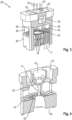
- shows a perspective view of the clamping component,
- Figure 4
- shows a perspective cut view of the clamping component,
- Figure 5
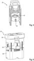
- shows a partial cut view of a second embodiment of the clamping component,
- Figure 6
- shows a third embodiment of the clamping component,
- Figure 7
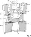
- shows a perspective cut view of a forth embodiment of the clamping component.
DETAILED DESCRIPTION OF PREFERRED EMBODIMENTS
-
As can be seen in figure 1, in order to transfer heat from a heater 10 to a wick 12 via a thermal interface membrane 14, the mentioned parts are firmly pressed together as further detailed below. In the embodiment shown, the heater 10 is accommodated in a heater nest 16 and has a width from left to right in the figures, as well as a surface area slightly larger than that of the heater 10 and essentially the same as that of the surface of the wick 12 contacting the membrane 14. The wick 12 is typically solid and presents a porous structure. The wick 12 can for example be made from ceramic. Moreover, starting from its surface contacting the membrane, the wick 12 widens to a width, or diameter in case of an essentially circular wick, of about 3 to 4 times the width of the membrane 14. Moreover, towards a mouthpiece at the top, as further detailed below with reference to figure 2, the wick has side walls 16, at the top of which the wick 12 is supported in the cartridge as also further detailed below with reference to figure 2. In its interior, the wick 12 is adapted to receive liquid to be vaporized, to which heat is transferred from the heater 10 via the membrane 14 and the wick 12. Further, the porous wick 12 is essentially saturated by liquid to be vaporized. Side 16 and bottom walls of the wick 12 essentially have the same wall thickness. The wick 12 defines one or several airflow channels allowing the air and vaporized liquid to pass through the wick 12. For example, the porous structure of the wick 12 can be adapted to form such airflow channels.
-
As can be taken from figure 2, the wick 12 is part of the cartridge 20 which is connectable to a heater part 22 comprising the heater 10. In the embodiment shown, the heater 10 essentially protrudes from the heater part 22, and the heater nest 16 is surrounded by a gasket 24 in the cartridge 20 for sealing. The heater part 22 is provided with a battery to power the heater 10 and comprises for example a controller to control the operation of the heater 10.
-
In use, as already indicated in figure 1, the heater 10 is in surface contact with the membrane 14 for transferring heat to the wick 12. In figure 2, 26 indicates a clamping component further detailed below, which is surrounded by a seal 28 in order to avoid liquid to be vaporized, which is essentially accommodated in the space 30, from leaking. The clamping component 26 and the seal 28 have inlets 32 for liquid to be vaporized which will, as a consequence, flow downwards in figure 2 into the interior of wick 12, where it is heated and vaporized so as to be drawn, together with air, through outlet 34, when a user applies appropriate under pressure at the mouthpiece 36. The outlet 34 essentially extends from above the wick 12, substantially centrally through space 30 to the outside of the cartridge 20. In figure 2 arrow A indicates the clamping force applied by the clamping component 26 so as to clamp the membrane 14 against the wick 12.
-
Figure 3 shows the clamping component 26, which is essentially cuboid with various side windows 38 and a lower, essentially a central opening 40 allowing insertion of the heater from below as shown in figure 2 and an upper, essentially central opening 42, through which air and vapor can flow towards the outlet 34 shown in figure 2 and as indicated by arrows B.
-
Arrows C in the lower part indicate airflow between plural trusses 44 essentially extending radially and all around the lower opening 40. For the sake of clarity, the front wall of clamping component 26 is omitted, but surrounds, like side walls 46 and a back wall 48 the trusses 44. As mentioned, air can flow between the trusses 44 after entering the cartridge through one or more air inlets 50 shown in figure 2 and can then essentially flow around wick 12 and be drawn from the outlet 34 together with vapor created by heating liquid in the wick 12 and its interior. In figure 3, liquid inlets 32 are indicated at the top of the clamping component 26.
-
Essentially the same components are derivable from figure 4 and denoted therein, with an annular surface 52 clamping the membrane 14 not shown in figures 3 and 4 against the wick, which is also not shown in the mentioned figures and supported at another surface 54 at its top. The annular surface 52 can delimit the central opening 40. The cartridge axis is essentially vertical in all of the figures, and the mentioned surfaces 52 and 54 extend essentially perpendicular or transversally to the cartridge axis which, particularly, corresponds to the direction, in which vapor and air can be drawn through outlet 34, when the device is used. The surface 54 supporting the wick 12 at its top can also be annular and can extend for example in contact with a periphery of the wick 12. Thus, the wick 12 can be abutted against this surface 54 when it is clamped by the clamping component 26. The distance between the surfaces 52, 54 according to the cartridge axis corresponds for example to a thickness of the wick 12 together with the membrane 14. In a general case, the distance between the surfaces 52, 54 according to the cartridge axis is chosen so as to clamp the membrane 14 and the wick 12 between these surfaces 52, 54.
-
Figure 5 shows an alternative embodiment of the clamping component 26, in which two ribs 56 arranged diametrically opposite are present around the lower opening 40 of the clamping component 26. Such ribs 56 also guide the airflow and can be configured to increase rigidity. In particular, the ribs 56 shown can be significantly wider and/or longer in the direction of the cartridge axis. In other words, they can extend all the way to the upper and/or lower end of the opening 40 and/or they can be wider in a left and right direction of figure 5. Moreover, further ribs, for example two additional ribs diametrically opposite at the left and right according to figure 5, can be present. The ribs 56 and/or trusses 44 essentially provide sufficient rigidity to the part having the surface 52 so as to enable surface 52 to apply the clamping force while at the same time maintaining sufficient air channels around the surface 52.
-
Figure 6 shows an alternative embodiment of the clamping component 26 comprising two pieces 58, in the case shown separated at about the center of windows 38 (figure 3), which can be connected and schematically indicated by one or more screws 60 and/or snap connections not shown.
-
Figure 7 shows another alternative embodiment, which essentially corresponds to that of figures 2 and 3, with the exception of a separate ceramic ring 62 constituting the surface 52, clamping the membrane 14 against the wick 12 supported in the clamping component 26 at its upper part with a wick seal 64 in between. As indicated above, heater 10 of the heater part of the device can be inserted through opening 40 so as to be in contact with the membrane 14. In other words, the clamping surface 52 essentially surrounds the heater 10, implying that the heater surface is slightly smaller than that of the membrane 14. In the embodiment shown, the surface 52 essentially contacts a ring-shaped surface of the membrane having a maximum width of 0.3 mm. Contact between the heater 10 and the membrane 14 will transfer heat to the wick 12 so that liquid entering through inlets 32 will be heated and vaporized and can be drawn by a user as indicated by arrows B.