EP4475445A1 - Verfahren und vorrichtung zur einstellung der antennenleistung, elektronische vorrichtung und lesbares speichermedium - Google Patents
Verfahren und vorrichtung zur einstellung der antennenleistung, elektronische vorrichtung und lesbares speichermedium Download PDFInfo
- Publication number
- EP4475445A1 EP4475445A1 EP23766071.7A EP23766071A EP4475445A1 EP 4475445 A1 EP4475445 A1 EP 4475445A1 EP 23766071 A EP23766071 A EP 23766071A EP 4475445 A1 EP4475445 A1 EP 4475445A1
- Authority
- EP
- European Patent Office
- Prior art keywords
- antenna
- uwb
- switching switch
- electronic device
- state
- Prior art date
- Legal status (The legal status is an assumption and is not a legal conclusion. Google has not performed a legal analysis and makes no representation as to the accuracy of the status listed.)
- Pending
Links
Images


Classifications
-
- H—ELECTRICITY
- H04—ELECTRIC COMMUNICATION TECHNIQUE
- H04W—WIRELESS COMMUNICATION NETWORKS
- H04W52/00—Power management, e.g. Transmission Power Control [TPC] or power classes
- H04W52/04—Transmission power control [TPC]
- H04W52/18—TPC being performed according to specific parameters
-
- H—ELECTRICITY
- H04—ELECTRIC COMMUNICATION TECHNIQUE
- H04B—TRANSMISSION
- H04B1/00—Details of transmission systems, not covered by a single one of groups H04B3/00 - H04B13/00; Details of transmission systems not characterised by the medium used for transmission
- H04B1/38—Transceivers, i.e. devices in which transmitter and receiver form a structural unit and in which at least one part is used for functions of transmitting and receiving
- H04B1/3827—Portable transceivers
- H04B1/3833—Hand-held transceivers
- H04B1/3838—Arrangements for reducing RF exposure to the user, e.g. by changing the shape of the transceiver while in use
-
- H—ELECTRICITY
- H04—ELECTRIC COMMUNICATION TECHNIQUE
- H04B—TRANSMISSION
- H04B1/00—Details of transmission systems, not covered by a single one of groups H04B3/00 - H04B13/00; Details of transmission systems not characterised by the medium used for transmission
- H04B1/38—Transceivers, i.e. devices in which transmitter and receiver form a structural unit and in which at least one part is used for functions of transmitting and receiving
- H04B1/40—Circuits
- H04B1/401—Circuits for selecting or indicating operating mode
-
- Y—GENERAL TAGGING OF NEW TECHNOLOGICAL DEVELOPMENTS; GENERAL TAGGING OF CROSS-SECTIONAL TECHNOLOGIES SPANNING OVER SEVERAL SECTIONS OF THE IPC; TECHNICAL SUBJECTS COVERED BY FORMER USPC CROSS-REFERENCE ART COLLECTIONS [XRACs] AND DIGESTS
- Y02—TECHNOLOGIES OR APPLICATIONS FOR MITIGATION OR ADAPTATION AGAINST CLIMATE CHANGE
- Y02D—CLIMATE CHANGE MITIGATION TECHNOLOGIES IN INFORMATION AND COMMUNICATION TECHNOLOGIES [ICT], I.E. INFORMATION AND COMMUNICATION TECHNOLOGIES AIMING AT THE REDUCTION OF THEIR OWN ENERGY USE
- Y02D30/00—Reducing energy consumption in communication networks
- Y02D30/70—Reducing energy consumption in communication networks in wireless communication networks
Definitions
- the present application belongs to the technical field of communication, and in particular to an antenna power adjustment method and apparatus, an electronic device and a readable storage medium.
- SAR Specific Absorption Rate
- whether it is necessary to reduce the conducting power of the antenna of the whole machine is determined mainly based on detecting the user's use state, such as acquiring the distance between the user's body and the electronic device by capacitance measurement. Since the measured capacitance value is positively related to the distance between the body and the antenna, when the measured capacitance value reaches a value, it is determined that the user's body is very close to the antenna of the electronic device, and the SAR reduction mode is activated to reduce the conducting power of the antenna.
- capacitance measurement requires the arrangement of a special metal conductor inside the electronic device as the SAR sensor plate, which forms a capacitance value with the human body when the human body comes near, and whether SAR reduction is required is determined by measuring the capacitance value.
- a special metal conductor inside the electronic device as the SAR sensor plate, which forms a capacitance value with the human body when the human body comes near, and whether SAR reduction is required is determined by measuring the capacitance value.
- the metal conductor will occupy the internal space of the electronic device and affect the design of other devices inside the electronic device, which will increase the thickness and weight of the electronic device, consequently affecting the user experience.
- the metal conductor used as a SAR sensor plate is limited in measurement directions in capacitance measurement, which may result in inaccurate measurement results.
- the present application aims to provide an antenna power adjustment method and apparatus, an electronic device and a readable storage medium to solve the problems of occupation of the internal space of the electronic device and mutual influence between the SAR-reducing capacitance measurement metal conductor and the ultra-wideband (UWB) antenna.
- UWB ultra-wideband
- an embodiment of the present application provides an antenna power adjustment method, applied to an electronic device including a radio frequency antenna, a UWB antenna, a UWB chip, a proximity detection apparatus and a switching switch.
- the UWB antenna is electrically connected to the switching switch.
- the switching switch has a first connecting terminal and a second connecting terminal. The first connecting terminal is electrically connected to the proximity detection apparatus. The second connecting terminal is electrically connected to the UWB chip.
- the switching switch is switchable between different states.
- the method includes:
- the UWB antenna is communicated with the UWB chip via the switching switch, and the electronic device receives and transmits a signal via the UWB antenna.
- an embodiment of the present application provides an antenna power adjustment apparatus, applied to an electronic device including a radio frequency antenna, a UWB antenna, a UWB chip, a proximity detection apparatus and a switching switch.
- the UWB antenna is electrically connected to the switching switch.
- the switching switch has a first connecting terminal and a second connecting terminal. The first connecting terminal is electrically connected to the proximity detection apparatus. The second connecting terminal is electrically connected to the UWB chip.
- the switching switch is switchable between different states.
- the apparatus includes:
- the UWB antenna is communicated with the proximity detection apparatus via the switching switch, the proximity detection apparatus is configured to obtain a capacitance signal of the UWB antenna, and the electronic device adjusts the transceiving power of the radio frequency antenna according to the capacitance signal.
- the UWB antenna is communicated with the UWB chip via the switching switch, and the electronic device receives and transmits a signal via the UWB antenna.
- an embodiment of the present application provides an electronic device, including a processor and a memory.
- the memory stores a program or an instruction runnable on the processor, and the program or the instruction, when being executed by the processor, implements steps of the method according to the first aspect.
- an embodiment of the present application provides a readable storage medium, storing a program or an instruction.
- the program or the instruction when being executed by a processor, implements steps of the method according to the first aspect.
- the UWB antenna and the SAR-reducing capacitance measurement metal conductor are combined, so that the UWB antenna not only has the function of receiving and transmitting the UWB signal, but also can be used as a plate in SAR-reducing capacitance measurement.
- the SAR-reducing measurement accuracy of the electronic device can be improved by utilizing the advantage of omni-directional radiation of the UWB antenna without increasing external devices, and the space occupied inside the electronic device is reduced.
- the UWB antenna can be applied in the electronic device without interference.
- a feature limited by “first” or “second” in this specification and claims of the present application may explicitly or implicitly include one or more of the features.
- a plurality of/multiple means two or more than two.
- “and/or” used in this specification and the claims represents at least one of the connected objects, and the character “/” generally indicates an “or” relationship between the connected objects.
- orientation or position relationships indicated by the terms such as “center”, “longitudinal”, “transverse”, “length”, “width”, “thickness”, “on”, “below”, “front”, “back”, “left”, “right”, “vertical”, “horizontal”, “top”, “bottom”, “inside”, “outside”, “clockwise”, “anticlockwise”, “axial direction”, “radial direction”, and “circumferential direction” are based on orientation or position relationships shown in the accompanying drawings, and are used only for ease and brevity of illustration and description, rather than indicating or implying that the mentioned apparatus or component needs to have a particular orientation or needs to be constructed and operated in a particular orientation. Therefore, such terms should not be construed as limiting of the present application.
- FIG. 2 is a flowchart I of an antenna power adjustment method provided by an embodiment of the present application.
- the antenna power adjustment method provided by this embodiment of the present application may be applied to an electronic device.
- the electronic device may be, for example, a mobile phone, a tablet computer, a notebook computer, or the like.
- the electronic device includes a radio frequency antenna (not shown in FIG. 2 ), a UWB antenna 1, a UWB chip 2, a proximity detection apparatus 3 and a switching switch 4.
- the UWB antenna 1 is electrically connected to the switching switch 4.
- the switching switch 4 has a first connecting terminal 41 and a second connecting terminal 42.
- the first connecting terminal 41 is electrically connected to the proximity detection apparatus 3.
- the second connecting terminal 42 is electrically connected to the UWB chip 2.
- the switching switch 4 is switchable between different states.
- the method may include step 2100 and step 2200, which will be described in detail below.
- the UWB antenna 1 When the switching switch 4 is in the first state, the UWB antenna 1 is communicated with the proximity detection apparatus 3 via the switching switch 4, the proximity detection apparatus 3 is configured to obtain a capacitance signal of the UWB antenna 1, and the electronic device adjusts a transceiving power of the radio frequency antenna according to the capacitance signal.
- the electronic device includes a switching switch 4.
- the switching switch 4 may be a single-pole double-throw switch.
- the UWB antenna 1 is electrically connected to a fixed terminal of the switching switch 4.
- the switching switch 4 further includes a control terminal, and the control terminal includes a first connecting terminal 41 and a second connecting terminal 42.
- the first connecting terminal 41 is electrically connected to the proximity detection apparatus 3, so that the UWB antenna 1 can be electrically connected to the proximity detection apparatus 3 via the switching switch 4.
- the UWB antenna 1 is used as a SAR-reducing capacitance measurement metal conductor.
- the proximity detection apparatus 3 When a user's body is in proximity to the electronic device, the proximity detection apparatus 3 is configured to obtain a capacitance signal formed between the user's body and the UWB antenna 1.
- the electronic device may adjust the transceiving power of the radio frequency antenna of the electronic device according to the capacitance signal obtained by the proximity detection apparatus 3.
- the electronic device determines that the user is close to the electronic device and triggers the reduction of the transceiving power of the radio frequency antenna of the electronic device, thereby reducing the SAR value of the electronic device.
- the capacitance signal formed between the user and the UWB antenna 1 i.e., the capacitance signal of the UWB antenna 1 obtained by the proximity detection apparatus 3
- the electronic device does not perform the function of adjusting the transceiving power of the radio frequency antenna of the electronic device.
- the user may transmit a UWB request to the electronic device by a user input device on the electronic device, and the electronic device may receive the UWB request.
- the first input is the UWB request transmitted by the user to the electronic device by the user input device.
- Step 2200 Adjust, in response to the first input, the switching switch 4 to a second state, and reduce the transceiving power of the radio frequency antenna.
- the user may transmit the UWB request to the electronic device by the user input device on the electronic device; and after the electronic device receives the UWB request, the electronic device may be controlled to activate the application program for adjusting the state of the switching switch 4 so as to adjust the switching switch 4 to the second state, and in a case that the switching switch 4 is in the second state, the transceiving power of the radio frequency antenna of the electronic device is reduced.
- the transceiving power of the radio frequency antenna should be reduced to reduce SAR so as to avoid the influence of high radiation power on the human body.
- the electronic device includes a switching switch 4.
- the switching switch 4 may be a single-pole double-throw switch.
- the UWB antenna 1 in the electronic device is electrically connected to a fixed terminal of the switching switch 4.
- the switching switch 4 further includes a control terminal, and the control terminal includes a first connecting terminal 41 and a second connecting terminal 42. Different from the case where the switching switch 4 is in the first state, when the switching switch 4 is in the second state, the first connecting terminal 41 is not electrically connected to the proximity detection apparatus 3, and the second connecting terminal 42 is electrically connected to the UWB chip 2 of the electronic device, so that the UWB antenna 1 is electrically connected to the UWB chip 2 via the switching switch 4.
- the electronic device After receiving the UWB request inputted by the user to the electronic device by the user input device, the electronic device considers that the user is using the electronic device, and the function of reducing the transceiving power of the radio frequency antenna of the electronic device can be triggered.
- the electronic device determines whether to reduce the SAR according to the use scene.
- the radio frequency antenna of the electronic device operates to produce electromagnetic radiation.
- the electronic device may detect that the user's body is very close to the electronic device by the positioning function of the UWB antenna 1.
- the electronic device needs to activate the reduction of the transmitting power of the radio frequency antenna (i.e., to reduce the SAR value), so that the radiation level of the electronic device is controlled within a safe range, thereby protecting the user.
- the electronic device detects that the user's body is far from the electronic device by the UWB positioning function, the electronic device does not perform the function of reducing the maximum transmitting power of the radio frequency antenna.
- the UWB antenna 1 when the switching switch 4 of the electronic device is in the second state, the UWB antenna 1 is electrically connected to the UWB chip 2 via the switching switch 4.
- the UWB antenna 1 may perform its own function as an antenna, and the electronic device may receive and transmit a signal via the UWB antenna 1, thereby realizing the function of UWB positioning of the electronic device.
- the switching switch 4 of the electronic device has two different states, namely the first state and the second state, so that the electronic device can control the UWB antenna 1 to activate different application programs according to different states of the switching switch 4.
- the UWB antenna 1 may be used as a SAR-reducing capacitance measurement metal conductor, and may also perform its own function as a UWB antenna, so that the UWB antenna has multiple functions.
- the UWB antenna 1 is arranged inside the electronic device, for example, between the motherboard and the back cover.
- the UWB antenna 1 is shared by the proximity detection apparatus 3 and the UWB chip 2, and controlled by the switching switch 4.
- One UWB antenna 1 can perform different functions, so that the UWB antenna has multiple functions.
- using the UWB antenna 1 as the SAR-reducing capacitance measurement metal conductor can save the metal conductor additionally arranged inside the electronic device, which reduces the space occupied inside the electronic device and can reduce the weight of the electronic device to some extent, thereby being beneficial to realizing a light and thin electronic device.
- the SAR-reducing capacitance measurement metal conductor and the UWB antenna are combined, which replaces the solution of arranging a capacitive SAR-reducing sensor metal antenna (i.e., SAR-reducing antennas) in the electronic device.
- the existing capacitive SAR-reducing sensor metal antenna and the UWB antenna are concentrated between the motherboard and the back cover inside the electronic device, which will increase the volume and weight of the electronic device and affect the user experience.
- the capacitive SAR-reducing sensor metal antenna is directly omitted, it is no longer shared by other antenna units in the electronic device, thereby avoiding affecting the design of antennas in the complete electronic device.
- the combination of the SAR-reducing capacitance measurement conductor and the UWB antenna can reduce the material cost.
- the UWB antenna 1 may exert its own function, i.e., the UWB positioning function, and may also be used as a metal plate for capacitance measurement to form a capacitance value with the user's body, so as to be used in SAR-reducing detection. That is, the UWB antenna 1 has both its own function and a compatible function. The two functions are used in different periods and do not interfere with each other, so that the UWB antenna has multiple functions.
- the existing metal conductor used as a SAR sensor plate is limited in measurement directions in capacitance measurement, which may result in inaccurate measurement results.
- the UWB antenna 1 used in this embodiment of the present application has the advantages of wide radiation range and omni-directional detection, which can improve the detection accuracy.
- the UWB antenna 1 and the SAR-reducing capacitance measurement metal conductor are combined, so that the UWB antenna 1 not only has the function of receiving and transmitting the UWB signal, but also can be used as a plate in SAR-reducing capacitance measurement.
- the SAR-reducing measurement accuracy of the electronic device can be improved by utilizing the advantage of omni-directional radiation of the UWB antenna 1 without increasing external devices, and the space occupied inside the electronic device is reduced.
- the UWB antenna 1 can be applied in the electronic device without interference.
- FIG. 3 is a flowchart II of an antenna power adjustment method provided by an embodiment of the present application.
- the method may further include step 3100 to step 3300, which will be described in detail below.
- Step 3100 Obtain a first communication signal between the UWB antenna 1 and a first tag when the switching switch 4 is in the second state, where the first tag is a UWB tag arranged on a target object.
- the switching switch 4 of the electronic device is in the second state
- the UWB antenna 1 is electrically connected to the UWB chip 2 via the switching switch 4, and the UWB antenna 1 performs its own function as an antenna.
- the electronic device establishes UWB communication with an external UWB tag or the like via the UWB antenna 1 and the UWB chip 2, the UWB tag is pre-arranged on the target object, and the electronic device can obtain a first communication signal between the UWB antenna 1 and the UWB tag on the target object when the switching switch 4 is in the second state.
- the target object is the user of the electronic device.
- UWB tags attached to the head, trunk and other parts of the human body may also detect the distance from the human body.
- the electronic device may flexibly reduce the SAR according to detection results of different parts.
- the target object is the user
- the UWB tag is directly attached to the user's body.
- Step 3200 Determine a first distance between the target object and the electronic device according to the first communication signal.
- Step 3300 Adjust the switching switch to the first state in a case that the first distance is smaller than a preset distance.
- the UWB antenna 1 is electrically connected to the UWB chip 2 via the switching switch 4, and the electronic device can control the UWB antenna 1 and the UWB chip 2 to cooperate to determine the distance (i.e., the first distance) between the target object and the electronic device after receiving the first communication signal between the UWB antenna and the first tag, thereby determining the size of the distance between the target object and the electronic device.
- the switching switch 4 is readjusted to the first state.
- this embodiment of the present application further uses a two-stage user's body proximity detection process.
- the positioning function of the UWB antenna 1 is used to perform omni-directional proximity detection between the wearable device/UWB tag on the user's body and the electronic device; and then, the UWB antenna 1 is used as the SAR-reducing capacitance measurement metal conductor (SAR Sensor plate) to perform user's body proximity detection so as to reconfirm whether the user's body is in proximity to the electronic device, thereby improving the detection accuracy.
- SAR Sensor plate SAR-reducing capacitance measurement metal conductor
- the method may further include step 5100, which will be described in detail below.
- the method further includes:
- Step 5100 Reduce the transceiving power of the radio frequency antenna when a first capacitance value obtained by the proximity detection apparatus 3 meets a preset threshold.
- the first capacitance value is a capacitance value obtained by the proximity detection apparatus 3 via the UWB antenna 1.
- the UWB antenna 1 and the UWB chip 2 of the electronic device cooperate to perform the function of directional distance measurement of the UWB. If the first distance between the target object and the electronic device obtained by the electronic device is smaller than the preset distance, the electronic device may adjust the switching switch 4 to the first state.
- the UWB antenna 1 is used as the SAR-reducing capacitance measurement metal conductor (SAR Sensor plate) to perform user's body proximity detection.
- the electronic device determines that the user is in proximity to the electronic device and triggers the reduction of the transceiving power of the radio frequency antenna of the electronic device, thereby reducing the SAR value of the electronic device.
- the first capacitance value is the capacitance signal obtained by the proximity detection apparatus 3 via the UWB antenna 1, i.e., the capacitance signal/capacitance value formed between the user's body and the UWB antenna 1.
- the electronic device when the capacitance signal formed between the user's body and the UWB antenna 1 (i.e., the capacitance signal of the UWB antenna 1 obtained by the proximity detection apparatus 3) is smaller than the preset threshold, the electronic device does not perform the function of adjusting the transceiving power of the radio frequency antenna of the electronic device.
- multiple UWB antennas 1 are provided, the UWB antennas 1 are patch antennas, and the switching switch 4 is a single-pole multi-throw switch.
- the multiple UWB antennas 1 are respectively electrically connected to the switching switch 4.
- the switching switch 4 includes multiple control terminals.
- the UWB antennas 1 are arranged in one-to-one correspondence to the control terminals, and each of the control terminals includes the first connecting terminal 41 and the second connecting terminal 42.
- Each of the first connecting terminals 41 is electrically connected to a connecting port on the proximity detection apparatus 3, and each of the second connecting terminals 42 is electrically connected to an antenna switch 5 and electrically connected to a connecting port on the UWB chip 2 via the antenna switch 5.
- the switching switch 4 is a single-pole multi-throw switch.
- the switching switch 4 includes four control terminals.
- the UWB antennas 1 are arranged in one-to-one correspondence to the control terminals.
- Each of the control terminals includes a first connecting terminal 41 and a second connecting terminal 42.
- the four UWB antennas 1 arranged can radiate to different directions, so that the proximity of the user's body can be detected in multiple directions, and the detection result is more accurate.
- the specific number of the UWB antennas 1 is not limited to four, and may also be one, two, three or more, which can be flexibly adjusted according to the space in the electronic device and is not specifically limited in the embodiment embodiments of the present application. If the space in the electronic device is small, one UWB antenna 1 will be enough.
- the proximity detection apparatus 3 is a SAR sensor.
- the UWB antenna 1 which is a metal plate structure, may be used as a metal conductor for SAR-reducing capacitance measurement to detect the change in the capacitance, thereby determining whether the user's body is in proximity to the electronic device and further determining whether the electronic device triggers SAR reduction.
- the UWB antenna 1 has the UWB positioning function, and can realize multi-directional accurate positioning.
- the antenna power adjustment apparatus provided by this embodiment of the present application is applied to an electronic device.
- the electronic device includes a radio frequency antenna, a UWB antenna 1, a UWB chip 2, a proximity detection apparatus 3 and a switching switch 4.
- the UWB antenna 1 is electrically connected to the switching switch 4.
- the switching switch 4 has a first connecting terminal 41 and a second connecting terminal 42.
- the first connecting terminal 41 is electrically connected to the proximity detection apparatus 3.
- the second connecting terminal 42 is electrically connected to the UWB chip 2.
- the switching switch 4 is switchable between different states.
- an embodiment of the present application further provides an antenna power adjustment apparatus 400, including a receiving module 401 and a switching module 402.
- the receiving module 401 is configured to receive a first input when the switching switch 4 is in a first state.
- the switching module 402 is configured to adjust, in response to the first input, the switching switch 4 to a second state, and reduce a transceiving power of the radio frequency antenna.
- the UWB antenna 1 When the switching switch 4 is in the first state, the UWB antenna 1 is communicated with the proximity detection apparatus 3 via the switching switch, the proximity detection apparatus 3 is configured to obtain a capacitance signal of the UWB antenna 1, and the electronic device adjusts the transceiving power of the radio frequency antenna according to the capacitance signal.
- the UWB antenna 1 is communicated with the UWB chip 2 via the switching switch 4, and the electronic device receives and transmits a signal via the UWB antenna 1.
- the first acquisition module 403 is configured to obtain a first communication signal between the UWB antenna 1 and a first tag when the switching switch 4 is in the second state.
- the first tag is a UWB tag arranged on a target object.
- the antenna power adjustment apparatus 400 further includes a second acquisition module 406.
- the second acquisition module 406 is configured to reduce the transceiving power of the radio frequency antenna when a first capacitance value obtained by the proximity detection apparatus 3 meets a preset threshold.
- the first capacitance value is a capacitance value obtained by the proximity detection apparatus 3 via the UWB antenna 1.
- multiple UWB antennas 1 are provided, the UWB antennas 1 are patch antennas, and the switching switch 4 is a single-pole multi-throw switch.
- the multiple UWB antennas 1 are respectively electrically connected to the switching switch 4.
- the switching switch 4 includes multiple control terminals.
- the UWB antennas 1 are arranged in one-to-one correspondence to the control terminals, and each of the control terminals includes the first connecting terminal 41 and the second connecting terminal 42.
- Each of the first connecting terminals 41 is electrically connected to a connecting port on the proximity detection apparatus 3, and each of the second connecting terminals 42 is electrically connected to an antenna switch 5 and electrically connected to a connecting port on the UWB chip 2 via the antenna switch 5.
- An ordinary SAR-reducing antenna (which is used as a SAR-reducing capacitance measurement metal conductor in the prior art) can only realize the proximity detection of the user's body in one direction.
- the UWB antenna 1 with the UWB positioning function can realize multi-directional accurate positioning, and determine whether the user's body is in proximity to the electronic device more comprehensively.
- the UWB antenna 1, which is also used as a SAR-reducing capacitance measurement metal conductor can reconfirm whether the human body is in proximity, thereby improving the detection accuracy.
- the antenna power adjustment apparatus in this embodiment of the present application may be an electronic device or a component in an electronic device, for example, an integrated circuit or a chip.
- the electronic device may be a terminal or other devices other than the terminal.
- the electronic device may be a mobile phone, a tablet computer, a notebook computer, a palm computer, an in-vehicle electronic device, a mobile internet device (Mobile Internet Device, MID), an augmented reality (augmented reality, AR)/virtual reality (virtual reality, VR) device, a robot, a wearable device, an ultra-mobile personal computer (ultra-mobile personal computer, UMPC), a netbook, or a personal digital assistant (personal digital assistant, PDA), and may also be a server, a network attached storage (Network Attached Storage, NAS), a personal computer (personal computer, PC), a television (television, TV), a teller machine, or an automated machine, which are not specifically limited in this embodiment of the present application.
- Network Attached Storage Network Attache
- the antenna power adjustment apparatus in this embodiment of the present application may be an apparatus with an operating system.
- the operating system may be an Android (Android) operating system, may be an iOS operating system, or may be another possible operating system, which is not specifically limited in this embodiment of the present application.
- the antenna power adjustment apparatus provided by this embodiment of the present application can implement all processes implemented by the method embodiments of FIG. 1 , FIG. 3 and FIG. 4 , details of which are omitted here for brevity.
- an embodiment of the present application further provides an electronic device 500, including a processor 501 and a memory 502.
- the memory 502 stores a program or an instruction runnable on the processor 501.
- the program or the instruction when being executed by the processor 501, implements steps of the embodiment of the antenna power adjustment method, and can achieve the same technical effects. To avoid repetition, details are not described herein again.
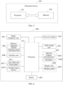
- FIG. 6 is a schematic diagram of a hardware structure of an electronic device for implementing an embodiment of the present application.
- the electronic device 600 includes, but not limited to, components such as a radio frequency unit 601, a network module 602, an audio output unit 603, an input unit 604, a sensor 605, a display unit 606, a user input unit 607, an interface unit 608, a memory 609, a processor 610, and an antenna power adjustment apparatus.
- components such as a radio frequency unit 601, a network module 602, an audio output unit 603, an input unit 604, a sensor 605, a display unit 606, a user input unit 607, an interface unit 608, a memory 609, a processor 610, and an antenna power adjustment apparatus.
- the electronic device 600 may further include a power supply (such as a battery) for supplying power to the components.
- the power supply may be logically connected to the processor 610 through a power management system, thereby implementing functions such as charging, discharging, and power consumption management by using the power management system.
- the structure of the electronic device shown in FIG. 6 does not constitute a limitation to the electronic device, and the electronic device may include more or fewer components than shown, or combine some components, or have different component arrangements, which will not be described in detail.
- the UWB antenna 1 When the switching switch 4 is in the first state, the UWB antenna 1 is communicated with the proximity detection apparatus 3 via the switching switch 4, the proximity detection apparatus 3 is configured to obtain a capacitance signal of the UWB antenna 1, and the electronic device adjusts the transceiving power of the radio frequency antenna according to the capacitance signal.
- the UWB antenna and the SAR-reducing capacitance measurement metal conductor are combined, so that the UWB antenna not only has the function of receiving and transmitting the UWB signal, but also can be used as a plate in SAR-reducing capacitance measurement.
- the SAR-reducing measurement accuracy of the electronic device can be improved by utilizing the advantage of omni-directional radiation of the UWB antenna without increasing external devices, and the space occupied inside the electronic device is reduced.
- the UWB antenna can be applied in the electronic device without interference.
- the processor 610 is configured to obtain a first communication signal between the UWB antenna and a first tag when the switching switch is in the second state, where the first tag is a UWB tag arranged on a target object; determine a first distance between the target object and the electronic device according to the first communication signal; and adjust the switching switch to the first state in a case that the first distance is smaller than a preset distance.
- the processor 610 is further configured to reduce the transceiving power of the radio frequency antenna when a first capacitance value obtained by the proximity detection apparatus meets a preset threshold.
- the first capacitance value is a capacitance value obtained by the proximity detection apparatus via the UWB antenna.
- the touch panel 6071 may include two parts: a touch detection apparatus and a touch controller.
- the another input device 6072 may include, but is not limited to, a physical keyboard, a functional key (such as a volume control key or a switch key), a track ball, a mouse, and a joystick, which are not repeated herein.
- the memory 609 may be configured to store software programs and various pieces of data.
- the memory 609 may mainly include a first storage area for storing the program or instruction and a second storage area for storing data.
- the first storage area may store an operating system, an application program or instruction required by at least one function (for example, a sound playback function and an image display function), and the like.
- the memory 609 may include a volatile memory or a non-volatile memory, or the memory 609 may include both a volatile memory and a non-volatile memory.
- the non-volatile memory may be a read-only memory (Read-Only Memory, ROM), a programmable ROM (Programmable ROM, PROM), an erasable PROM (Erasable PROM, EPROM), an electrically EPROM (Electrically EEPROM) or a flash memory.
- ROM Read-Only Memory
- PROM programmable ROM
- PROM erasable PROM
- EPROM electrically EPROM
- EEPROM Electrically EEPROM
- the processor 610 may include one or more processing units.
- the processor 610 integrates an application processor and a modem processor.
- the application processor mainly processes operations related to the operating system, the user interface and application programs, and the modem processor, such as a baseband processor, mainly processes wireless communication signals. It can be understood that the foregoing modem processor may not be integrated into the processor 610.
- the processor is the processor in the electronic device in the above embodiment.
- the readable storage medium includes a computer-readable storage medium, such as a computer read-only memory (ROM), a random access memory (RAM), a magnetic disk, an optical disk or the like.
- An embodiment of the present application further provides a chip, including a processor and a communication interface.
- the communication interface is coupled to the processor.
- the processor is configured to run a program or an instruction to implement processes of the embodiment of the antenna power adjustment method, and can achieve the same technical effects. In order to avoid repetition, details will not be described here.
- the methods according to the above embodiments can be implemented by software plus a necessary general hardware platform, and certainly, they can also be implemented by hardware, but in many cases the former is a better implementation.
- the technical solution of the present application essentially or for the part that contributes to the prior art can be embodied in the form of a software product, and the computer software product is stored in a storage medium (such as an ROM/RAM, a magnetic disk or an optical disk) and includes several instructions to enable a terminal facility (which may be a mobile phone, a computer, a server, an air conditioner, a network device or the like) to execute the method described in the embodiments of this application.
Landscapes
- Engineering & Computer Science (AREA)
- Computer Networks & Wireless Communication (AREA)
- Signal Processing (AREA)
- Transceivers (AREA)
- Support Of Aerials (AREA)
Applications Claiming Priority (2)
| Application Number | Priority Date | Filing Date | Title |
|---|---|---|---|
| CN202210228905.9A CN114679198B (zh) | 2022-03-09 | 2022-03-09 | 天线功率调整方法、装置、电子设备及可读存储介质 |
| PCT/CN2023/080401 WO2023169494A1 (zh) | 2022-03-09 | 2023-03-09 | 天线功率调整方法、装置、电子设备及可读存储介质 |
Publications (2)
| Publication Number | Publication Date |
|---|---|
| EP4475445A1 true EP4475445A1 (de) | 2024-12-11 |
| EP4475445A4 EP4475445A4 (de) | 2025-05-28 |
Family
ID=82072224
Family Applications (1)
| Application Number | Title | Priority Date | Filing Date |
|---|---|---|---|
| EP23766071.7A Pending EP4475445A4 (de) | 2022-03-09 | 2023-03-09 | Verfahren und vorrichtung zur einstellung der antennenleistung, elektronische vorrichtung und lesbares speichermedium |
Country Status (4)
| Country | Link |
|---|---|
| US (1) | US20240430812A1 (de) |
| EP (1) | EP4475445A4 (de) |
| CN (1) | CN114679198B (de) |
| WO (1) | WO2023169494A1 (de) |
Family Cites Families (14)
| Publication number | Priority date | Publication date | Assignee | Title |
|---|---|---|---|---|
| WO2010138453A2 (en) * | 2009-05-26 | 2010-12-02 | Skycross,Inc. | Methods for reducing near-field radiation and specific absorption rate (sar) values in communications devices |
| CN103428314A (zh) * | 2012-05-24 | 2013-12-04 | 中兴通讯股份有限公司 | 一种调整移动终端辐射方向的方法及移动终端 |
| TWI536658B (zh) * | 2013-10-03 | 2016-06-01 | 緯創資通股份有限公司 | 行動通訊裝置及其輻射功率調整方法 |
| KR102456541B1 (ko) * | 2016-06-22 | 2022-10-19 | 삼성전자 주식회사 | Sar 저감을 위한 안테나 스위칭 방법 및 이를 지원하는 전자 장치 |
| WO2018120240A1 (zh) * | 2016-12-30 | 2018-07-05 | 华为技术有限公司 | 一种调整电磁波辐射参数的装置、方法以及存储介质 |
| CN210724786U (zh) * | 2019-12-20 | 2020-06-09 | 深圳市大疆创新科技有限公司 | 信号传输装置、无人机及无人机系统 |
| CN111245983A (zh) * | 2020-01-09 | 2020-06-05 | Oppo广东移动通信有限公司 | 天线控制方法和装置、电子设备、计算机可读存储介质 |
| CN111405652B (zh) * | 2020-04-23 | 2025-02-07 | 闻泰通讯股份有限公司 | 电子设备、辐射功率控制方法、装置及存储介质 |
| CN111953823A (zh) * | 2020-07-29 | 2020-11-17 | 北京小米移动软件有限公司 | 接近传感器状态检测方法、装置及终端 |
| CN112886978B (zh) * | 2021-01-28 | 2022-06-24 | 维沃移动通信有限公司 | 射频电路、电子设备及控制方法 |
| CN112968275B (zh) * | 2021-02-03 | 2023-05-26 | 维沃移动通信有限公司 | 电子设备 |
| US20210211152A1 (en) * | 2021-03-19 | 2021-07-08 | Intel Corporation | Radiation safety mechanism based on wi-fi sensing |
| CN113949409B (zh) * | 2021-09-24 | 2023-06-16 | 维沃移动通信有限公司 | 射频电路和电子设备 |
| CN113890935B (zh) * | 2021-09-28 | 2023-06-13 | Oppo广东移动通信有限公司 | 电子设备及天线发射功率的调节方法 |
-
2022
- 2022-03-09 CN CN202210228905.9A patent/CN114679198B/zh active Active
-
2023
- 2023-03-09 EP EP23766071.7A patent/EP4475445A4/de active Pending
- 2023-03-09 WO PCT/CN2023/080401 patent/WO2023169494A1/zh not_active Ceased
-
2024
- 2024-09-06 US US18/827,362 patent/US20240430812A1/en active Pending
Also Published As
| Publication number | Publication date |
|---|---|
| US20240430812A1 (en) | 2024-12-26 |
| CN114679198B (zh) | 2024-01-30 |
| WO2023169494A1 (zh) | 2023-09-14 |
| CN114679198A (zh) | 2022-06-28 |
| EP4475445A4 (de) | 2025-05-28 |
Similar Documents
| Publication | Publication Date | Title |
|---|---|---|
| US11688931B2 (en) | Antenna for wearable device | |
| EP3435199B1 (de) | Verfahren, mobiles endgerät und nichttransitorisches computerlesbares speichermedium zur anpassung der abtastfrequenz eines berührungsbildschirms | |
| US12034202B2 (en) | Antenna structure and electronic device including the same | |
| CN113676238B (zh) | 到达角度确定方法及相关产品 | |
| US12387644B2 (en) | Electronic device and user interface display method | |
| EP3392962A1 (de) | Elektronische vorrichtung mit antenne mit verwendung des gehäuses davon | |
| US11762428B2 (en) | Electronic device and method for controlling power of the same | |
| US10766440B2 (en) | Electronic device including antenna using conductive member included in housing | |
| US12493393B2 (en) | Method for operating flexible display, and electronic device | |
| US11741869B2 (en) | Electronic device including variable display and method of operating the same | |
| US20220129139A1 (en) | Electronic device and method for controlling display of a plurality of objects on wearable display device | |
| US12235379B2 (en) | Electronic device and method for detecting external object by using antenna array | |
| US11824529B2 (en) | Circuit for adjusting resonance frequency and electronic device including same | |
| EP4475445A1 (de) | Verfahren und vorrichtung zur einstellung der antennenleistung, elektronische vorrichtung und lesbares speichermedium | |
| US12513658B2 (en) | Electronic device and method for determining a location of a device | |
| CN218160823U (zh) | 天线装置及智能终端 | |
| KR20220064269A (ko) | 전자 장치 및 사용자 인터페이스 표시 방법 | |
| US12436618B2 (en) | Electronic device including dual vibration motors, and method therefor | |
| US20250181295A1 (en) | Electronic device comprising flexible display, and electronic device control method | |
| US20250080161A1 (en) | Electronic device for performing communication based on a plurality of communication methods and operating method thereof | |
| US12236075B2 (en) | Electronic device including flexible display and operating method thereof | |
| US20250190016A1 (en) | Electronic device comprising slidable display and method for operating same | |
| US20240231537A1 (en) | Electronic device and control method therefor | |
| EP4216202A1 (de) | Steuerungsverfahren für flexible anzeige und elektronische vorrichtung zur unterstützung davon | |
| KR20250049148A (ko) | 전자 장치 및 이를 이용한 송신 신호 제어 방법 |
Legal Events
| Date | Code | Title | Description |
|---|---|---|---|
| STAA | Information on the status of an ep patent application or granted ep patent |
Free format text: STATUS: THE INTERNATIONAL PUBLICATION HAS BEEN MADE |
|
| PUAI | Public reference made under article 153(3) epc to a published international application that has entered the european phase |
Free format text: ORIGINAL CODE: 0009012 |
|
| STAA | Information on the status of an ep patent application or granted ep patent |
Free format text: STATUS: REQUEST FOR EXAMINATION WAS MADE |
|
| 17P | Request for examination filed |
Effective date: 20240906 |
|
| AK | Designated contracting states |
Kind code of ref document: A1 Designated state(s): AL AT BE BG CH CY CZ DE DK EE ES FI FR GB GR HR HU IE IS IT LI LT LU LV MC ME MK MT NL NO PL PT RO RS SE SI SK SM TR |
|
| REG | Reference to a national code |
Ref country code: DE Ref legal event code: R079 Free format text: PREVIOUS MAIN CLASS: H04B0001401000 Ipc: H04B0001382700 |
|
| A4 | Supplementary search report drawn up and despatched |
Effective date: 20250428 |
|
| RIC1 | Information provided on ipc code assigned before grant |
Ipc: H04W 52/18 20090101ALI20250422BHEP Ipc: H04B 1/401 20150101ALI20250422BHEP Ipc: H04B 1/3827 20150101AFI20250422BHEP |
|
| DAV | Request for validation of the european patent (deleted) | ||
| DAX | Request for extension of the european patent (deleted) |