EP4475388A1 - Multi-phase feeding device for wireless power transmission and method of controlling same - Google Patents
Multi-phase feeding device for wireless power transmission and method of controlling same Download PDFInfo
- Publication number
- EP4475388A1 EP4475388A1 EP23750006.1A EP23750006A EP4475388A1 EP 4475388 A1 EP4475388 A1 EP 4475388A1 EP 23750006 A EP23750006 A EP 23750006A EP 4475388 A1 EP4475388 A1 EP 4475388A1
- Authority
- EP
- European Patent Office
- Prior art keywords
- inverter
- power supply
- output
- coil
- pickup
- Prior art date
- Legal status (The legal status is an assumption and is not a legal conclusion. Google has not performed a legal analysis and makes no representation as to the accuracy of the status listed.)
- Pending
Links
Images


Classifications
-
- B—PERFORMING OPERATIONS; TRANSPORTING
- B60—VEHICLES IN GENERAL
- B60L—PROPULSION OF ELECTRICALLY-PROPELLED VEHICLES; SUPPLYING ELECTRIC POWER FOR AUXILIARY EQUIPMENT OF ELECTRICALLY-PROPELLED VEHICLES; ELECTRODYNAMIC BRAKE SYSTEMS FOR VEHICLES IN GENERAL; MAGNETIC SUSPENSION OR LEVITATION FOR VEHICLES; MONITORING OPERATING VARIABLES OF ELECTRICALLY-PROPELLED VEHICLES; ELECTRIC SAFETY DEVICES FOR ELECTRICALLY-PROPELLED VEHICLES
- B60L53/00—Methods of charging batteries, specially adapted for electric vehicles; Charging stations or on-board charging equipment therefor; Exchange of energy storage elements in electric vehicles
- B60L53/10—Methods of charging batteries, specially adapted for electric vehicles; Charging stations or on-board charging equipment therefor; Exchange of energy storage elements in electric vehicles characterised by the energy transfer between the charging station and the vehicle
- B60L53/12—Inductive energy transfer
-
- H—ELECTRICITY
- H01—ELECTRIC ELEMENTS
- H01F—MAGNETS; INDUCTANCES; TRANSFORMERS; SELECTION OF MATERIALS FOR THEIR MAGNETIC PROPERTIES
- H01F27/00—Details of transformers or inductances, in general
- H01F27/24—Magnetic cores
-
- H—ELECTRICITY
- H01—ELECTRIC ELEMENTS
- H01F—MAGNETS; INDUCTANCES; TRANSFORMERS; SELECTION OF MATERIALS FOR THEIR MAGNETIC PROPERTIES
- H01F27/00—Details of transformers or inductances, in general
- H01F27/28—Coils; Windings; Conductive connections
-
- H—ELECTRICITY
- H01—ELECTRIC ELEMENTS
- H01F—MAGNETS; INDUCTANCES; TRANSFORMERS; SELECTION OF MATERIALS FOR THEIR MAGNETIC PROPERTIES
- H01F27/00—Details of transformers or inductances, in general
- H01F27/34—Special means for preventing or reducing unwanted electric or magnetic effects, e.g. no-load losses, reactive currents, harmonics, oscillations, leakage fields
- H01F27/36—Electric or magnetic shields or screens
-
- H—ELECTRICITY
- H01—ELECTRIC ELEMENTS
- H01F—MAGNETS; INDUCTANCES; TRANSFORMERS; SELECTION OF MATERIALS FOR THEIR MAGNETIC PROPERTIES
- H01F38/00—Adaptations of transformers or inductances for specific applications or functions
- H01F38/14—Inductive couplings
-
- H—ELECTRICITY
- H02—GENERATION; CONVERSION OR DISTRIBUTION OF ELECTRIC POWER
- H02J—ELECTRIC POWER NETWORKS; CIRCUIT ARRANGEMENTS OR SYSTEMS FOR SUPPLYING OR DISTRIBUTING ELECTRIC POWER; SYSTEMS FOR STORING ELECTRIC ENERGY
- H02J50/00—Circuit arrangements or systems for wireless supply or distribution of electric power
- H02J50/005—Mechanical details of housing or structure aiming to accommodate the power transfer means, e.g. mechanical integration of coils, antennas or transducers into emitting or receiving devices
-
- H—ELECTRICITY
- H02—GENERATION; CONVERSION OR DISTRIBUTION OF ELECTRIC POWER
- H02J—ELECTRIC POWER NETWORKS; CIRCUIT ARRANGEMENTS OR SYSTEMS FOR SUPPLYING OR DISTRIBUTING ELECTRIC POWER; SYSTEMS FOR STORING ELECTRIC ENERGY
- H02J50/00—Circuit arrangements or systems for wireless supply or distribution of electric power
- H02J50/10—Circuit arrangements or systems for wireless supply or distribution of electric power using inductive coupling
-
- H—ELECTRICITY
- H02—GENERATION; CONVERSION OR DISTRIBUTION OF ELECTRIC POWER
- H02J—ELECTRIC POWER NETWORKS; CIRCUIT ARRANGEMENTS OR SYSTEMS FOR SUPPLYING OR DISTRIBUTING ELECTRIC POWER; SYSTEMS FOR STORING ELECTRIC ENERGY
- H02J50/00—Circuit arrangements or systems for wireless supply or distribution of electric power
- H02J50/40—Circuit arrangements or systems for wireless supply or distribution of electric power using two or more transmitting or receiving devices
- H02J50/402—Circuit arrangements or systems for wireless supply or distribution of electric power using two or more transmitting or receiving devices the two or more transmitting or the two or more receiving devices being integrated in the same unit, e.g. power mats with several coils or antennas with several sub-antennas
-
- H—ELECTRICITY
- H02—GENERATION; CONVERSION OR DISTRIBUTION OF ELECTRIC POWER
- H02J—ELECTRIC POWER NETWORKS; CIRCUIT ARRANGEMENTS OR SYSTEMS FOR SUPPLYING OR DISTRIBUTING ELECTRIC POWER; SYSTEMS FOR STORING ELECTRIC ENERGY
- H02J50/00—Circuit arrangements or systems for wireless supply or distribution of electric power
- H02J50/70—Circuit arrangements or systems for wireless supply or distribution of electric power involving the reduction of electric, magnetic or electromagnetic leakage fields
-
- H—ELECTRICITY
- H02—GENERATION; CONVERSION OR DISTRIBUTION OF ELECTRIC POWER
- H02J—ELECTRIC POWER NETWORKS; CIRCUIT ARRANGEMENTS OR SYSTEMS FOR SUPPLYING OR DISTRIBUTING ELECTRIC POWER; SYSTEMS FOR STORING ELECTRIC ENERGY
- H02J50/00—Circuit arrangements or systems for wireless supply or distribution of electric power
- H02J50/90—Circuit arrangements or systems for wireless supply or distribution of electric power involving detection or optimisation of position, e.g. alignment
-
- H—ELECTRICITY
- H02—GENERATION; CONVERSION OR DISTRIBUTION OF ELECTRIC POWER
- H02M—APPARATUS FOR CONVERSION BETWEEN AC AND AC, BETWEEN AC AND DC, OR BETWEEN DC AND DC, AND FOR USE WITH MAINS OR SIMILAR POWER SUPPLY SYSTEMS; CONVERSION OF DC OR AC INPUT POWER INTO SURGE OUTPUT POWER; CONTROL OR REGULATION THEREOF
- H02M1/00—Details of apparatus for conversion
- H02M1/42—Circuits or arrangements for compensating for or adjusting power factor in converters or inverters
-
- H—ELECTRICITY
- H02—GENERATION; CONVERSION OR DISTRIBUTION OF ELECTRIC POWER
- H02M—APPARATUS FOR CONVERSION BETWEEN AC AND AC, BETWEEN AC AND DC, OR BETWEEN DC AND DC, AND FOR USE WITH MAINS OR SIMILAR POWER SUPPLY SYSTEMS; CONVERSION OF DC OR AC INPUT POWER INTO SURGE OUTPUT POWER; CONTROL OR REGULATION THEREOF
- H02M7/00—Conversion of AC power input into DC power output; Conversion of DC power input into AC power output
- H02M7/42—Conversion of DC power input into AC power output without possibility of reversal
- H02M7/44—Conversion of DC power input into AC power output without possibility of reversal by static converters
- H02M7/48—Conversion of DC power input into AC power output without possibility of reversal by static converters using discharge tubes with control electrode or semiconductor devices with control electrode
- H02M7/493—Conversion of DC power input into AC power output without possibility of reversal by static converters using discharge tubes with control electrode or semiconductor devices with control electrode the static converters being arranged for operation in parallel
Definitions
- the present invention relates to a multiphase power supply apparatus for wireless power transmission and a control method thereof, and more particularly, to a multiphase power supply apparatus including a plurality of power supply coils, each coil capable of being supplied with a current having a different phase and a method for controlling the multiphase power supply apparatus when it is determined that a misalignment with corresponding pickup has occurred.
- Wireless charging is revolutionizing the experience and safety of charging devices when compared to traditional conductive charging.
- the use of wireless charging in the electric transport sector is becoming increasingly common, with a shift towards designs that prioritize high power, power density, versatility and scalability.
- the coupling coefficient between the power supply coils is greater than 0.3, which can complicate the control of the multiphase power supply and cause losses in power transmission. Furthermore, if there is a deviation in the alignment between the power supply and the pickup, the output of each coil of the pickup may become uneven.
- the present invention aims to solve the above problems by providing a multiphase power supply apparatus for wireless power transmission having a plurality of power supply coils, wherein the coupling coefficients between different power supply coils are low, and wherein the apparatus can be controlled to ensure uniform output over the pickup coils even when there are deviations in the alignment between the pickup and the power supply coils. It also aims to provide a control method for such a multiphase power supply apparatus for wireless power transmission.
- a power supply apparatus for wireless power transmission, a first power supply coil; a first inverter electrically connected with the first power supply coil; a second power supply coil having a coupling coefficient with the first power supply coil below a predetermined value; a second inverter electrically connected to the second power supply coil and controllable independently of the first inverter; and a control unit for regulating a phase difference between an output of the first inverter and an output of the second inverter when it is determined that a deviation in alignment with a corresponding pickup has occurred.
- the first power supply coil and the second power supply coil are a combination of a circular coil and a DD coil or a combination of a DD coil and a DD coil.
- the first power supply coil and the second power supply coil may be arranged to at least partially overlap each other.
- the power supply apparatus further comprises a power supply core and the power supply core includes protruded portions that fill empty spaces remaining after the first power supply coil or the second power supply coil is not superimposed on each other.
- the coupling coefficient between the first power supply coil and the second power supply coil is 0.3 or less.
- control unit determines that a deviation in alignment with the corresponding pickup has occurred when a difference between the output of the first inverter and the output of the second inverter is greater than a predetermined value, and adjusts the phase difference between the output of the first inverter and the output of the second inverter so that the difference is less than or equal to the predetermined value.
- control unit determines that a deviation in alignment with the corresponding pickup has occurred when a difference between a duty ratio of the first inverter and a duty ratio of the second inverter is greater than a predetermined value, and adjusts the phase difference between the output of the first inverter and the output of the second inverter so that the difference is less than or equal to the predetermined value.
- control unit determines that a deviation in alignment with the corresponding power supply has occurred when a difference between outputs of the rectifiers connected to pickup coils of the corresponding pickup is greater than a predetermined value, and adjusts the phase difference between the output of the first inverter and the output of the second inverter so that the difference between the outputs is less than or equal to the predetermined value.
- the control unit calculates a duty ratio of the first inverter and the second inverter for the output to reach the required level and, if the calculated duty ratio is less than a predetermined upper limit value, the control unit applies the calculated duty ratio or, if the calculated duty ratio is greater than the predetermined upper limit value, the control unit increases DC input voltages of the first inverter and the second inverter.
- the power supply apparatus may further comprises: a third power supply coil having a coupling coefficient with the first power supply coil and the second power supply coil below a predetermined value; a third inverter electrically connected to the third power supply coil and independently controllable with respect to the first inverter and the second inverter, and the control unit is capable of controlling a phase of the output of the third inverter.
- a method for controlling the power supply apparatus for wireless power transmission comprising the steps of: (a) determining whether a deviation in alignment with the corresponding pickup has occurred; and (b) adjusting a phase difference between an output of the first inverter and an output of the second inverter.
- step (a) determining that a deviation in alignment with the corresponding pickup has occurred if a difference between the output of the first inverter and the output of the second inverter is greater than a predetermined value and, in the step (b), adjusting the phase difference between the output of the first inverter and the output of the second inverter until the difference between the output of the first inverter and the output of the second inverter is less than or equal to the predetermined value.
- step (a) determining that a deviation in alignment with the corresponding pickup has occurred if a difference between a duty ratio of the first inverter and a duty ratio of the second inverter is greater than a predetermined value and, in the step (b), adjusting the phase difference between the output of the first inverter and the output of the second inverter until the difference between the duty ratio of the first inverter and the duty ratio of the second inverter is less than or equal to the predetermined value.
- step (a) determining that a deviation in alignment with the corresponding power supply unit has occurred if a difference between outputs of the respective rectifiers connected with pickup coils of the corresponding pickup is greater than a predetermined value and, in the step (b), adjusting the phase difference between the output of the first inverter and the output of the second inverter until the difference between the outputs of the respective rectifiers of the corresponding pickup is less than or equal to the predetermined value.
- step (b) adjusting the phase difference between the output of the first inverter and the output of the second inverter based on an estimated initial phase.
- the adjustment of the phase difference between the output of the first inverter and the output of the second inverter is made using an optimization algorithm.
- the optimization algorithm may be a gradient descent method and the gradient descent method may be based on predetermined angular intervals.
- the method may further comprise the steps of: (c) determining that an output of the corresponding pickup is at or above a required level; (d) calculating, if the output of the corresponding pickup in the step (c) is less than the required level, duty ratios of the first inverter and of the second inverter to reach the output to the required level; and (e) applying, if the duty ratios calculated in the step (d) are less than a predetermined upper limit value, the duty ratio, or, if greater than the upper limit value, increasing DC input voltages of the first inverter and the second inverter.
- the present invention provides a multiphase power supply for wireless power transmission in which the coupling coefficient between different power supply coils is low and the output of the power supply coils can be controlled to be uniform even when a deviation occurs in the alignment of the power supply coils with the pickup.
- a method in a multiphase power supply for wireless power transmission comprising a plurality of power supply coils, for controlling the output of the power supply coils to be uniform even when a deviation occurs in the alignment of the power supply coils with the pickup.
- FIG. 1 schematically illustrates a multiphase power supply system for wireless power transmission according to one embodiment of the present invention.
- the illustrated power supply system includes a power supply 100 comprising two power supply coils 110 and a pickup 200 comprising two corresponding pickup coils 210.
- the power supply coil 110 comprises a first power supply coil 111 and a second power supply coil 112.
- a coupling coefficient between the first power supply coil 111 and the second power supply coil 112 has a value substantially close to zero (0) when the power supply 100 and the pickup 200 are aligned.
- the pickup coil 210 comprises the same number of pickup coils as the power supply coil 110, namely two pickup coils 211, 212.
- the coupling coefficient of the first pickup coil 211 and the second pickup coil 212 has a value substantially close to zero (0) with the power supply 100 and the pickup 200 aligned.
- the coupling coefficients of the first power supply coil 111 and the second pickup coil 212 and the coupling coefficients of the second power supply coil 112 and the first pickup coil 211 also have values substantially close to zero (0).
- the power supply coils 111, 112 are each associated with a controllable inverter 121, 122.
- An impedance matching network 131, 132 is arranged between the power supply coils 111, 112 and the inverters 121, 122, respectively.
- a control unit (not shown) of the inverters 121, 122 controls the inverters 121, 122 such that, in the event of a deviation in the alignment between the power supply 100 and the pickup 200, the total output of the pickup 200 satisfies the required output, and the outputs of each of the pickup coils 211, 212 are uniform with each other. Specific control methods will be described later.
- the power supply 100 and the pickup 200 include a communication unit (not shown) for exchanging information.
- the power supply 100 can receive information required for controlling the power supply 100 according to the present invention, such as the amount of power required by the pickup 200, the output of each pickup coil, and the like.
- FIG. 2 illustrates an example of a power supply coil 110 and a pickup coil 210 satisfying the conditions described above.
- the illustrated power supply coil 110 comprises a DD coil as a first power supply coil 111, a circular coil as a second power supply coil 112, and further comprises a power supply core 113 and a shielding member 114.
- the pickup coil 210 likewise comprises a DD coil as a first pickup coil 211 and a circular coil as a second pickup coil 212, and further comprises a pickup core 213 and a shielding member 214.
- the coupling coefficient between the DD coil and the circular coil has a value substantially close to zero (0) . Therefore, the coupling coefficient between the first power supply coil 111, which is a DD coil, and the second power supply coil 112, which is a circular coil, is substantially zero (0). Furthermore, the coupling coefficient between the first power supply coil 111, which is a DD coil, and the second pickup coil 212, which is a circular coil, is also substantially zero (0).
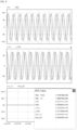
- FIG. 3 simulation-based values for the self-inductance, mutual inductance, and coupling coefficient between the power supply coil 110 and the pickup coil 210 shown in FIG. 2 are presented. Also, the values for each parameter are presented when the power supply coil 110 and the pickup coil 210 are in an aligned state, as well as when deviations occur in the x-direction and/or y-direction.
- the coupling coefficient between the first power supply coil, which is a DD coil, and the first pickup coil, which is also a DD coil, is 0.089
- the coupling coefficient between the second power supply coil and the second pickup coil, which are circular coils, respectively is 0.110.
- the output of each inverter of the power supply 100, the output of each coil of the pickup, and the duty ratio of each inverter of the power supply 100 are shown, in order from top to bottom, when the power supply 100 and the pickup 200 are aligned.
- the outputs of the inverters and the outputs of the pickup coils, except for the duty ratios are slightly different even when the power supply and the pickup are aligned.
- the duty ratio is shown to be the same by chance, but in practice, differences in duty ratio may occur. This is taken into account when controlling the power supply according to the present invention, i.e., even if there is a difference in these values, it is determined that there is no deviation between the power supply and the pickup within a certain range.
- the coupling coefficient between the first supply coil, which is a DD coil, and the second pickup coil, which is a circular coil, and the coupling coefficient between the second supply coil, which is a circular coil, and the first pickup coil, which is a DD coil is substantially zero (0).
- FIG. 3 shows, as an example, the change in inductance and coupling coefficient between each coil when the pickup is deviated 75 mm in the x-direction and 100 mm in the y-direction relative to the power supply. Due to these changes, the state of the power circuit connected to each power supply coil and the power circuit connected to each pickup coil changes. In particular, the misalignment of the power supply and the pickup will, in most cases, result in uneven output of each pickup coil.
- the present invention controls the power supply to ensure that the output of each pickup coil is uniform.
- FIG. 5 a flowchart of a method for controlling a multiphase power supply for wireless power transmission according to one embodiment of the present invention is schematically illustrated.
- the power supply 100 receives information about a required amount of power, for example, a target current required by the vehicle's battery, from the pickup 200 via a communication unit (not shown) S110.
- the power supply 100 determines an alignment status with the pickup 200 (S120).
- the alignment status is determined in three ways 1) comparing the magnitude of the difference between the outputs of the inverter connected to each power supply coil and the preset value, 2) comparing the magnitude of the difference between the outputs of the rectifier connected to each pickup coil and the preset value, and 3) comparing the magnitude of the difference between the duty ratio of the inverter connected to each power supply coil and the preset value.
- phase control according to the present invention is performed (S130). The specific method of phase control will be described later.
- the phase of the output of the inverter is determined based on the phase value determined by the phase control (S140) . Thereby, the output of each pickup coil is uniformized (see FIG. 7 ). The output of the pickup is then checked to ensure that it has reached the previously required level (S140). If the output of the pickup is lower than the required level, the duty ratio of the power supply inverter is calculated (S150) to bring the output to the required level. Since the devices comprising the inverter have a tolerable operating range, the duty ratio cannot be increased indefinitely. Therefore, a predetermined upper limit is set for the duty ratio of the inverter.
- the duty ratio of the inverter is adjusted to the calculated value because it is allowed as the operating range of the inverter. If the calculated duty ratio is larger than the upper limit value, after setting the duty ratio to the upper limit value, the magnitude of the DC input voltage of the inverter is increased so that the output of the pickup can reach the required level (S160).
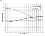
- FIG. 6 illustrates one embodiment of phase control according to the present invention.
- the output of each coil of the pickup is uniformized by adjusting the phase difference of the outputs of the inverter associated with each power supply coil.
- FIG. 6 illustrates the state in which the mutual inductance of each pickup coil changes when the phase difference of the outputs of each inverter is increased by 10 degrees in the simulation shown in FIG. 3 , when the x-directional deviation is 75 mm and the y-directional deviation is 100 mm.
- the mutual inductance (M_DD) of the first pickup coil (DD coil) is 5.25
- the mutual inductance (M_Circular) of the second pickup coil (circular coil) is 13.36.
- the output of the first and second pickup coils is very uneven. If the phase difference between the inverters of the power supply unit is increased by 10 degree intervals through phase control, the mutual inductance of the first pickup coil increases and the mutual inductance of the second pickup coil decreases. When the phase difference of the inverter is about 130 degrees, the mutual inductance of the two pickup coils has almost the same value. In this case, the output of the two pickup coils becomes almost uniform.
- FIG. 7 the output of the two pickup coils as the phase is varied is shown.
- the center graph shows the output of the two pickup coils when the phase difference is optimal
- the upper graph shows the output when the phase difference is 10 degrees less than optimal
- the lower graph shows the output when the phase difference is 10 degrees greater than optimal.
- FIGS. 6 and 7 illustrate simply varying the phase difference in 10 degree intervals
- a variety of known optimization algorithms can be used for more rapid control.
- a variety of optimization algorithms can be applied, including gradient descent, for example, PID control, search algorithms, and techniques using artificial intelligence.
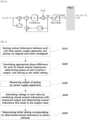
- FIG. 8 an example method of performing phase control using a gradient descent method is illustrated.
- current and previous measurements of the output current of each inverter of the power supply are provided as inputs.
- the difference between these measurements is normalized and multiplied by a predetermined ratio ( ⁇ , learning rate) to determine the phase difference value to be changed.
- the determined phase difference value is summed with the initial setting value to determine the phase of each inverter.
- the initial value may be zero (0), or it may be an estimated value as described later.
- an upper limit can be set in advance (Phase Limiter). Operate each inverter (Plant in FIG. 8 ) of the power supply with the determined phase value. Adjusting the phase difference between the outputs of the inverters can be done by fixing the phase of the output of one inverter and adjusting the phase of the output of another inverter, or by adjusting the outputs of multiple inverters simultaneously.
- FIG. 9 a method for estimating an initial set point in phase control and determining it to be a non-zero value is schematically illustrated.
- an appropriate phase difference for that location is determined as the initial setpoint.
- the mutual inductance between each coil in the case where the power supply and the pickup are aligned and in the case where they are misaligned is determined by simulation or experiment, and these values are stored (S210).
- the appropriate phase difference is calculated for each of the mutual inductances stored by simulation or experiment, and the phase of the output of each inverter is determined and stored as an initial setting (S220) .
- phase control the output of the pickup (or power supply) is measured (S230), and the voltage of each state is estimated by combining the previously stored mutual inductance and the measured output, and the mutual inductance that induces the largest value is determined (S240). The mutual inductance thus determined and the corresponding initial setting value are determined as an estimate of the phase (S250).
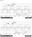
- FIG. 10 shows the experimental results of applying phase control to a multiphase power supply implemented in practice according to the present invention.
- the upper graph shows the duty and output of the two inverters of the power supply before phase control is applied, and the lower graph shows the duty and output of the inverters after phase control is applied.
- the phase difference between the two inverters was 85 degrees, which was changed to 120 degrees after phase control was applied.
- the duty ratios of the two inverters were different before the phase control was applied and became almost identical after the phase control was applied. It can be seen that the magnitudes of the outputs of the inverters are almost the same.
- the two coils of the power supply and the pickup are described as a DD coil and a circular coil, respectively, but the multiphase power supply of the present invention can be configured in various ways, provided that the coupling coefficient is less than a predetermined value (e.g., 0.3) .
- a predetermined value e.g. 0.25
- FIG. 11A a DD coil/DD coil combination is possible.
- FIG. 11B Also shown in FIG. 11B is a DD coil/DD coil combination, wherein a part of one DD coil is disposed on top of the other DD coil and the remaining part is disposed on the bottom of the other DD coil.
- space utilization is improved because the height at which the coils are stacked is reduced, and a uniform magnetic field is created because the average distance between each coil and the core is approximately the same.
- power density is improved and heat generation is reduced.
- the above description refers to a two-phase power supply, i.e., a power supply and a pickup each having two coils, but the control method of a multi-phase power supply according to the present invention can also be applied to a power supply having three or more phases.
- the power supply coil that induces a voltage close to the rated voltage is selected as the master, and the remaining two power supply coils are set as two slaves. Compare the output of the two slave power supply coils with the output of the master power supply coil, and perform output control including phase control on the slave power supply coil with the larger difference. In addition to phase control, the output control includes adjustment of the duty ratio as described above and adjustment of the inverter DC input voltage, and these adjustments are common to all power supply coils. Phase control is then performed on the other slave power supply coils. If the output of the pickup does not reach the required level at the first attempt, the process is repeated until the required level is reached.
- FIGS. 12A and 12B illustrate examples of three coil configurations for three-phase cases.
- the examples shown in both figures are circular/DD/DD configurations, but in the example shown in FIG. 12A , the circular coil houses two DD coils inside, while in the example shown in FIG. 12B , the circular coil and two DD coils are stacked in three layers.
- the former has the advantage of reducing the height of the combination of coils compared to the latter.
Landscapes
- Engineering & Computer Science (AREA)
- Power Engineering (AREA)
- Computer Networks & Wireless Communication (AREA)
- Transportation (AREA)
- Mechanical Engineering (AREA)
- Physics & Mathematics (AREA)
- Electromagnetism (AREA)
- Inverter Devices (AREA)
- Charge And Discharge Circuits For Batteries Or The Like (AREA)
- Current-Collector Devices For Electrically Propelled Vehicles (AREA)
Abstract
Description
- The present invention relates to a multiphase power supply apparatus for wireless power transmission and a control method thereof, and more particularly, to a multiphase power supply apparatus including a plurality of power supply coils, each coil capable of being supplied with a current having a different phase and a method for controlling the multiphase power supply apparatus when it is determined that a misalignment with corresponding pickup has occurred.
- Wireless charging is revolutionizing the experience and safety of charging devices when compared to traditional conductive charging. As wireless charging technology continues to evolve, the use of wireless charging in the electric transport sector is becoming increasingly common, with a shift towards designs that prioritize high power, power density, versatility and scalability.
- In the document titled 'A 50-kW three-phase wireless power transfer system using bipolar windings and series resonant networks for rotating magnetic fields' by PRIES, Jason, et al., published in IEEE Transactions on Power Electronics in 2019, a three-phase inductive wireless power transmission system utilizing bipolar phase windings is disclosed. The system utilized a rotating magnetic field to achieve temporally smoother power transfer characteristics than a single-phase system. The system also transmitted 50 kW with 95% efficiency across a 150 mm air gap when the power supply and pickup were aligned.
- However, in the power supply coil structure of the document, the coupling coefficient between the power supply coils is greater than 0.3, which can complicate the control of the multiphase power supply and cause losses in power transmission. Furthermore, if there is a deviation in the alignment between the power supply and the pickup, the output of each coil of the pickup may become uneven.
- The present invention aims to solve the above problems by providing a multiphase power supply apparatus for wireless power transmission having a plurality of power supply coils, wherein the coupling coefficients between different power supply coils are low, and wherein the apparatus can be controlled to ensure uniform output over the pickup coils even when there are deviations in the alignment between the pickup and the power supply coils. It also aims to provide a control method for such a multiphase power supply apparatus for wireless power transmission.
- To solve the above problems, according to one aspect of the present invention, there is provided a power supply apparatus for wireless power transmission, a first power supply coil; a first inverter electrically connected with the first power supply coil; a second power supply coil having a coupling coefficient with the first power supply coil below a predetermined value; a second inverter electrically connected to the second power supply coil and controllable independently of the first inverter; and a control unit for regulating a phase difference between an output of the first inverter and an output of the second inverter when it is determined that a deviation in alignment with a corresponding pickup has occurred.
- Preferably, the first power supply coil and the second power supply coil are a combination of a circular coil and a DD coil or a combination of a DD coil and a DD coil.
- The first power supply coil and the second power supply coil may be arranged to at least partially overlap each other.
- Preferably, the power supply apparatus further comprises a power supply core and the power supply core includes protruded portions that fill empty spaces remaining after the first power supply coil or the second power supply coil is not superimposed on each other.
- Preferably, the coupling coefficient between the first power supply coil and the second power supply coil is 0.3 or less.
- Preferably, the control unit determines that a deviation in alignment with the corresponding pickup has occurred when a difference between the output of the first inverter and the output of the second inverter is greater than a predetermined value, and adjusts the phase difference between the output of the first inverter and the output of the second inverter so that the difference is less than or equal to the predetermined value.
- Alternatively, the control unit determines that a deviation in alignment with the corresponding pickup has occurred when a difference between a duty ratio of the first inverter and a duty ratio of the second inverter is greater than a predetermined value, and adjusts the phase difference between the output of the first inverter and the output of the second inverter so that the difference is less than or equal to the predetermined value.
- Alternatively, the control unit determines that a deviation in alignment with the corresponding power supply has occurred when a difference between outputs of the rectifiers connected to pickup coils of the corresponding pickup is greater than a predetermined value, and adjusts the phase difference between the output of the first inverter and the output of the second inverter so that the difference between the outputs is less than or equal to the predetermined value.
- Preferably, if an output of the corresponding pickup is less than a required level, the control unit calculates a duty ratio of the first inverter and the second inverter for the output to reach the required level and, if the calculated duty ratio is less than a predetermined upper limit value, the control unit applies the calculated duty ratio or, if the calculated duty ratio is greater than the predetermined upper limit value, the control unit increases DC input voltages of the first inverter and the second inverter.
- The power supply apparatus may further comprises: a third power supply coil having a coupling coefficient with the first power supply coil and the second power supply coil below a predetermined value; a third inverter electrically connected to the third power supply coil and independently controllable with respect to the first inverter and the second inverter, and the control unit is capable of controlling a phase of the output of the third inverter.
- According to other aspect of the present invention, there is provided a method for controlling the power supply apparatus for wireless power transmission, comprising the steps of: (a) determining whether a deviation in alignment with the corresponding pickup has occurred; and (b) adjusting a phase difference between an output of the first inverter and an output of the second inverter.
- Preferably, in the step (a), determining that a deviation in alignment with the corresponding pickup has occurred if a difference between the output of the first inverter and the output of the second inverter is greater than a predetermined value and, in the step (b), adjusting the phase difference between the output of the first inverter and the output of the second inverter until the difference between the output of the first inverter and the output of the second inverter is less than or equal to the predetermined value.
- Preferably, in the step (a), determining that a deviation in alignment with the corresponding pickup has occurred if a difference between a duty ratio of the first inverter and a duty ratio of the second inverter is greater than a predetermined value and, in the step (b), adjusting the phase difference between the output of the first inverter and the output of the second inverter until the difference between the duty ratio of the first inverter and the duty ratio of the second inverter is less than or equal to the predetermined value.
- Preferably, in the step (a), determining that a deviation in alignment with the corresponding power supply unit has occurred if a difference between outputs of the respective rectifiers connected with pickup coils of the corresponding pickup is greater than a predetermined value and, in the step (b), adjusting the phase difference between the output of the first inverter and the output of the second inverter until the difference between the outputs of the respective rectifiers of the corresponding pickup is less than or equal to the predetermined value.
- Preferably, in the step (b), adjusting the phase difference between the output of the first inverter and the output of the second inverter based on an estimated initial phase. Preferably, in the step (b), the adjustment of the phase difference between the output of the first inverter and the output of the second inverter is made using an optimization algorithm.
- The optimization algorithm may be a gradient descent method and the gradient descent method may be based on predetermined angular intervals.
- The method may further comprise the steps of: (c) determining that an output of the corresponding pickup is at or above a required level; (d) calculating, if the output of the corresponding pickup in the step (c) is less than the required level, duty ratios of the first inverter and of the second inverter to reach the output to the required level; and (e) applying, if the duty ratios calculated in the step (d) are less than a predetermined upper limit value, the duty ratio, or, if greater than the upper limit value, increasing DC input voltages of the first inverter and the second inverter.
- The present invention provides a multiphase power supply for wireless power transmission in which the coupling coefficient between different power supply coils is low and the output of the power supply coils can be controlled to be uniform even when a deviation occurs in the alignment of the power supply coils with the pickup.
- Further, a method is provided, in a multiphase power supply for wireless power transmission comprising a plurality of power supply coils, for controlling the output of the power supply coils to be uniform even when a deviation occurs in the alignment of the power supply coils with the pickup.
-
-
FIG. 1 is a schematic drawing of a wireless power transmission system including a multiphase power supply according to the present invention. -
FIG. 2 is a drawing illustrating a configuration of a multiphase power supply and a corresponding pickup according to one embodiment of the present invention. -
FIG. 3 is a drawing illustrating a simulation calculation of the inductance and coupling coefficient between each coil of the multiphase power supply and the corresponding pickup shown inFIG. 2 . -
FIG. 4 is a drawing showing, in order from top to bottom, the output of the inverter of the multiphase power supply having the configuration shown inFIG. 3 , the output of the rectifier of the corresponding pickup, and the duty of the inverter. -
FIG. 5 is a flow diagram illustrating a method of controlling a multiphase power supply according to one embodiment of the present invention shown inFIG. 1 . -
FIG. 6 is a graph indicating a change in mutual inductance between a power supply coil and a pickup coil when changing phases according to phase control in a multiphase power supply having the configuration shown inFIG. 3 . -
FIG. 7 is a diagram illustrating a change in the output of a pickup corresponding to a phase change of 10 degrees in phase control according to the present invention. -
FIG. 8 is a drawing illustrating a case of applying a gradient descent method as an example of performing phase control according to the present invention by an optimization algorithm. -
FIG. 9 is a flow diagram illustrating a method of estimating and determining an initial phase setting in phase control according to the present invention. -
FIG. 10 is a diagram illustrating the results of measuring the duty and output of an inverter before performing phase control and the duty and output of an inverter after performing phase control in a multiphase power supply in which the control method according to the present invention is implemented. -
FIG. 11A is a drawing illustrating other embodiment of a multiphase power supply according to the present invention, wherein the combination of power supply coils is different. -
FIG. 11B is a drawing illustrating another embodiment of a multiphase power supply according to the present invention, wherein the combination of power supply coils is different. -
FIG. 12A is a drawing illustrating still another embodiment of a multiphase power supply according to the present invention, wherein there are three feeding coils. -
FIG. 12B is a drawing illustrating still another embodiment of a multiphase power supply according to the present invention, wherein there are three feeding coils. - Hereinafter, embodiments according to the present invention will be described in detail with reference to the accompanying drawings. The same or similar components are given the same or similar drawing designations, and redundant descriptions thereof are omitted. In describing the embodiments disclosed herein, detailed description of related known art is omitted if it is determined that such detailed description would obscure the essence of the embodiments disclosed herein. The accompanying drawings are intended to facilitate understanding of the embodiments disclosed herein, but the technical ideas disclosed herein are not limited by the accompanying drawings and should be understood to include all modifications, equivalents, or substitutions that are within the scope of the ideas and technology of the present invention.
- Terms containing ordinal numbers, such as first, second, and the like, may be used to describe various components, but such terms are used only to distinguish one component from another, and such components are not limited by such terms. Expressions in the singular include the plural, unless the context clearly indicates otherwise.
- The terms "including," "comprising," "having" or "having" as used herein are to be understood as limiting the presence of the features, steps, components or combinations thereof described and are not intended to exclude the possibility that one or more other features, steps, components or combinations thereof may be present or added.
-
FIG. 1 schematically illustrates a multiphase power supply system for wireless power transmission according to one embodiment of the present invention. The illustrated power supply system includes apower supply 100 comprising twopower supply coils 110 and apickup 200 comprising twocorresponding pickup coils 210. - The
power supply coil 110 comprises a firstpower supply coil 111 and a secondpower supply coil 112. A coupling coefficient between the firstpower supply coil 111 and the secondpower supply coil 112 has a value substantially close to zero (0) when thepower supply 100 and thepickup 200 are aligned. Thepickup coil 210 comprises the same number of pickup coils as thepower supply coil 110, namely twopickup coils first pickup coil 211 and thesecond pickup coil 212 has a value substantially close to zero (0) with thepower supply 100 and thepickup 200 aligned. Furthermore, the coupling coefficients of the firstpower supply coil 111 and thesecond pickup coil 212 and the coupling coefficients of the secondpower supply coil 112 and thefirst pickup coil 211 also have values substantially close to zero (0). However, this is for ease of description and is not necessarily limiting, and the coupling coefficient between each of the coils described above may have a value greater than zero (0). For example, it may have a value of about 0.3, as in the above mentioned document. - The power supply coils 111, 112 are each associated with a
controllable inverter impedance matching network inverters inverters inverters power supply 100 and thepickup 200, the total output of thepickup 200 satisfies the required output, and the outputs of each of the pickup coils 211, 212 are uniform with each other. Specific control methods will be described later. - Further, the
power supply 100 and thepickup 200 include a communication unit (not shown) for exchanging information. Through the communication unit, thepower supply 100 can receive information required for controlling thepower supply 100 according to the present invention, such as the amount of power required by thepickup 200, the output of each pickup coil, and the like. -
FIG. 2 illustrates an example of apower supply coil 110 and apickup coil 210 satisfying the conditions described above. - The illustrated
power supply coil 110 comprises a DD coil as a firstpower supply coil 111, a circular coil as a secondpower supply coil 112, and further comprises apower supply core 113 and a shieldingmember 114. Thepickup coil 210 likewise comprises a DD coil as afirst pickup coil 211 and a circular coil as asecond pickup coil 212, and further comprises apickup core 213 and a shieldingmember 214. - The coupling coefficient between the DD coil and the circular coil has a value substantially close to zero (0) . Therefore, the coupling coefficient between the first
power supply coil 111, which is a DD coil, and the secondpower supply coil 112, which is a circular coil, is substantially zero (0). Furthermore, the coupling coefficient between the firstpower supply coil 111, which is a DD coil, and thesecond pickup coil 212, which is a circular coil, is also substantially zero (0). - In
FIG. 3 , simulation-based values for the self-inductance, mutual inductance, and coupling coefficient between thepower supply coil 110 and thepickup coil 210 shown inFIG. 2 are presented. Also, the values for each parameter are presented when thepower supply coil 110 and thepickup coil 210 are in an aligned state, as well as when deviations occur in the x-direction and/or y-direction. - In the state where the
power supply 100 and thepickup 200 are aligned (X: 0 mm, Y: 0 mm), the coupling coefficient between the first power supply coil, which is a DD coil, and the first pickup coil, which is also a DD coil, is 0.089, and the coupling coefficient between the second power supply coil and the second pickup coil, which are circular coils, respectively, is 0.110. Even if the values of the two coupling coefficients are designed to match, it is difficult to match them precisely in an actual implemented power supply and pickup. In the simulation, the values of the two coupling coefficients are set differently to reflect this. As a result, even when thepower supply 100 and thepickup 200 are aligned, the output of eachpickup coil 210 has a slightly different value. InFIG. 4 , the output of each inverter of thepower supply 100, the output of each coil of the pickup, and the duty ratio of each inverter of thepower supply 100 are shown, in order from top to bottom, when thepower supply 100 and thepickup 200 are aligned. As can be seen, the outputs of the inverters and the outputs of the pickup coils, except for the duty ratios, are slightly different even when the power supply and the pickup are aligned. In the illustrated case, the duty ratio is shown to be the same by chance, but in practice, differences in duty ratio may occur. This is taken into account when controlling the power supply according to the present invention, i.e., even if there is a difference in these values, it is determined that there is no deviation between the power supply and the pickup within a certain range. More specific details will be provided in the following description of the control method. On the other hand, in the aligned state (X: 0 mm, Y: 0 mm), the coupling coefficient between the first supply coil, which is a DD coil, and the second pickup coil, which is a circular coil, and the coupling coefficient between the second supply coil, which is a circular coil, and the first pickup coil, which is a DD coil, is substantially zero (0). - The coupling coefficient between the power supply coils and the pickup coils varies when the power supply and pickup are out of alignment.
FIG. 3 shows, as an example, the change in inductance and coupling coefficient between each coil when the pickup is deviated 75 mm in the x-direction and 100 mm in the y-direction relative to the power supply. Due to these changes, the state of the power circuit connected to each power supply coil and the power circuit connected to each pickup coil changes. In particular, the misalignment of the power supply and the pickup will, in most cases, result in uneven output of each pickup coil. - Since it is desirable that the output of each pickup coil is uniform, the present invention controls the power supply to ensure that the output of each pickup coil is uniform.
- In
FIG. 5 , a flowchart of a method for controlling a multiphase power supply for wireless power transmission according to one embodiment of the present invention is schematically illustrated. - The
power supply 100 receives information about a required amount of power, for example, a target current required by the vehicle's battery, from thepickup 200 via a communication unit (not shown) S110. Thepower supply 100 then determines an alignment status with the pickup 200 (S120). In the illustrated embodiment, the alignment status is determined in three ways 1) comparing the magnitude of the difference between the outputs of the inverter connected to each power supply coil and the preset value, 2) comparing the magnitude of the difference between the outputs of the rectifier connected to each pickup coil and the preset value, and 3) comparing the magnitude of the difference between the duty ratio of the inverter connected to each power supply coil and the preset value. If any of the three is greater than the preset value, it is judged that the power supply and pickup are misaligned. As described above with reference toFIG. 3 , by design, the three values should not differ in the aligned state, but since there are tolerances in the actual implemented power supply and pickup, a predetermined difference exists even in the aligned state. Therefore, if there is a difference within an allowed range, the power supply and the pickup are considered to be aligned. If it is determined that the power supply and the pickup are misaligned, that is, if any of the above three values is greater than the preset value, phase control according to the present invention is performed (S130). The specific method of phase control will be described later. - When all of the above three values become smaller than the preset value due to the phase control, the phase of the output of the inverter is determined based on the phase value determined by the phase control (S140) . Thereby, the output of each pickup coil is uniformized (see
FIG. 7 ). The output of the pickup is then checked to ensure that it has reached the previously required level (S140). If the output of the pickup is lower than the required level, the duty ratio of the power supply inverter is calculated (S150) to bring the output to the required level. Since the devices comprising the inverter have a tolerable operating range, the duty ratio cannot be increased indefinitely. Therefore, a predetermined upper limit is set for the duty ratio of the inverter. If the calculated duty ratio is less than the upper limit, the duty ratio of the inverter is adjusted to the calculated value because it is allowed as the operating range of the inverter. If the calculated duty ratio is larger than the upper limit value, after setting the duty ratio to the upper limit value, the magnitude of the DC input voltage of the inverter is increased so that the output of the pickup can reach the required level (S160). -
FIG. 6 illustrates one embodiment of phase control according to the present invention. In the phase control according to the present invention, the output of each coil of the pickup is uniformized by adjusting the phase difference of the outputs of the inverter associated with each power supply coil.FIG. 6 illustrates the state in which the mutual inductance of each pickup coil changes when the phase difference of the outputs of each inverter is increased by 10 degrees in the simulation shown inFIG. 3 , when the x-directional deviation is 75 mm and the y-directional deviation is 100 mm. Initially, the mutual inductance (M_DD) of the first pickup coil (DD coil) is 5.25, and the mutual inductance (M_Circular) of the second pickup coil (circular coil) is 13.36. In this case, the output of the first and second pickup coils is very uneven. If the phase difference between the inverters of the power supply unit is increased by 10 degree intervals through phase control, the mutual inductance of the first pickup coil increases and the mutual inductance of the second pickup coil decreases. When the phase difference of the inverter is about 130 degrees, the mutual inductance of the two pickup coils has almost the same value. In this case, the output of the two pickup coils becomes almost uniform. InFIG. 7 , the output of the two pickup coils as the phase is varied is shown. The center graph shows the output of the two pickup coils when the phase difference is optimal, the upper graph shows the output when the phase difference is 10 degrees less than optimal, and the lower graph shows the output when the phase difference is 10 degrees greater than optimal. - While
FIGS. 6 and7 illustrate simply varying the phase difference in 10 degree intervals, a variety of known optimization algorithms can be used for more rapid control. A variety of optimization algorithms can be applied, including gradient descent, for example, PID control, search algorithms, and techniques using artificial intelligence. InFIG. 8 , an example method of performing phase control using a gradient descent method is illustrated. In the example shown, current and previous measurements of the output current of each inverter of the power supply are provided as inputs. The difference between these measurements is normalized and multiplied by a predetermined ratio (α, learning rate) to determine the phase difference value to be changed. The determined phase difference value is summed with the initial setting value to determine the phase of each inverter. The initial value may be zero (0), or it may be an estimated value as described later. To prevent the phase value determined at the output from exceeding a predetermined range, an upper limit can be set in advance (Phase Limiter). Operate each inverter (Plant inFIG. 8 ) of the power supply with the determined phase value. Adjusting the phase difference between the outputs of the inverters can be done by fixing the phase of the output of one inverter and adjusting the phase of the output of another inverter, or by adjusting the outputs of multiple inverters simultaneously. - In
FIG. 9 , a method for estimating an initial set point in phase control and determining it to be a non-zero value is schematically illustrated. In the example shown, after estimating in which direction the power supply and pickup are out of phase, an appropriate phase difference for that location is determined as the initial setpoint. First, the mutual inductance between each coil in the case where the power supply and the pickup are aligned and in the case where they are misaligned is determined by simulation or experiment, and these values are stored (S210). Then, the appropriate phase difference is calculated for each of the mutual inductances stored by simulation or experiment, and the phase of the output of each inverter is determined and stored as an initial setting (S220) . In phase control, the output of the pickup (or power supply) is measured (S230), and the voltage of each state is estimated by combining the previously stored mutual inductance and the measured output, and the mutual inductance that induces the largest value is determined (S240). The mutual inductance thus determined and the corresponding initial setting value are determined as an estimate of the phase (S250). - As described in
FIGS. 6 and7 , in the case of simply varying the phase difference, in addition to the problem that the time to reach the optimum value is prolonged, it may exceed the range allowed by the devices of the inverter. Therefore, by using the initial setting as described above, the time to reach the optimum value is reduced and the devices of the inverter are prevented from being damaged by overload. -
FIG. 10 shows the experimental results of applying phase control to a multiphase power supply implemented in practice according to the present invention. The upper graph shows the duty and output of the two inverters of the power supply before phase control is applied, and the lower graph shows the duty and output of the inverters after phase control is applied. As shown, before phase control was applied, the phase difference between the two inverters was 85 degrees, which was changed to 120 degrees after phase control was applied. Also, the duty ratios of the two inverters were different before the phase control was applied and became almost identical after the phase control was applied. It can be seen that the magnitudes of the outputs of the inverters are almost the same. - In the above embodiments, the two coils of the power supply and the pickup are described as a DD coil and a circular coil, respectively, but the multiphase power supply of the present invention can be configured in various ways, provided that the coupling coefficient is less than a predetermined value (e.g., 0.3) . For example, as shown in
FIG. 11A , a DD coil/DD coil combination is possible. - Also shown in
FIG. 11B is a DD coil/DD coil combination, wherein a part of one DD coil is disposed on top of the other DD coil and the remaining part is disposed on the bottom of the other DD coil. In the configuration shown, space utilization is improved because the height at which the coils are stacked is reduced, and a uniform magnetic field is created because the average distance between each coil and the core is approximately the same. In addition, power density is improved and heat generation is reduced. - The above description refers to a two-phase power supply, i.e., a power supply and a pickup each having two coils, but the control method of a multi-phase power supply according to the present invention can also be applied to a power supply having three or more phases.
- In the case of three power supply coils, the power supply coil that induces a voltage close to the rated voltage is selected as the master, and the remaining two power supply coils are set as two slaves. Compare the output of the two slave power supply coils with the output of the master power supply coil, and perform output control including phase control on the slave power supply coil with the larger difference. In addition to phase control, the output control includes adjustment of the duty ratio as described above and adjustment of the inverter DC input voltage, and these adjustments are common to all power supply coils. Phase control is then performed on the other slave power supply coils. If the output of the pickup does not reach the required level at the first attempt, the process is repeated until the required level is reached.
-
FIGS. 12A and 12B illustrate examples of three coil configurations for three-phase cases. The examples shown in both figures are circular/DD/DD configurations, but in the example shown inFIG. 12A , the circular coil houses two DD coils inside, while in the example shown inFIG. 12B , the circular coil and two DD coils are stacked in three layers. The former has the advantage of reducing the height of the combination of coils compared to the latter. - The foregoing detailed description is not to be construed as limiting in any respect and should be considered exemplary. The scope of the invention is to be determined by a reasonable interpretation of the appended claims, and all modifications within the equivalent scope of the invention are included in the scope of the invention.
Claims (19)
- A power supply apparatus for wireless power transmission, comprising:a first power supply coil;a first inverter electrically connected with the first power supply coil;a second power supply coil having a coupling coefficient with the first power supply coil below a predetermined value;a second inverter electrically connected to the second power supply coil and controllable independently of the first inverter; anda control unit for regulating a phase difference between an output of the first inverter and an output of the second inverter when it is determined that a deviation in alignment with a corresponding pickup has occurred.
- The power supply apparatus of claim 1, wherein the first power supply coil and the second power supply coil are a combination of a circular coil and a DD coil or a combination of a DD coil and a DD coil.
- The power supply apparatus of claim 2, wherein the first power supply coil and the second power supply coil are arranged to at least partially overlap each other.
- The power supply apparatus of claim 3, further comprising a power supply core, and wherein the power supply core includes protruded portions that fill empty spaces remaining after the first power supply coil or the second power supply coil is not superimposed on each other.
- The power supply apparatus of claim 1, wherein the coupling coefficient between the first power supply coil and the second power supply coil is 0.3 or less.
- The power supply apparatus of claim 1, wherein the control unit determines that a deviation in alignment with the corresponding pickup has occurred when a difference between the output of the first inverter and the output of the second inverter is greater than a predetermined value, and adjusts the phase difference between the output of the first inverter and the output of the second inverter so that the difference is less than or equal to the predetermined value.
- The power supply apparatus of claim 1, wherein the control unit determines that a deviation in alignment with the corresponding pickup has occurred when a difference between a duty ratio of the first inverter and a duty ratio of the second inverter is greater than a predetermined value, and adjusts the phase difference between the output of the first inverter and the output of the second inverter so that the difference is less than or equal to the predetermined value.
- The power supply apparatus of claim 1, wherein the control unit determines that a deviation in alignment with the corresponding power supply has occurred when a difference between outputs of the rectifiers connected to pickup coils of the corresponding pickup is greater than a predetermined value, and adjusts the phase difference between the output of the first inverter and the output of the second inverter so that the difference between the outputs is less than or equal to the predetermined value.
- The power supply apparatus of claim 1, wherein, if an output of the corresponding pickup is less than a required level, the control unit calculates a duty ratio of the first inverter and the second inverter for the output to reach the required level, and
wherein, if the calculated duty ratio is less than a predetermined upper limit value, the control unit applies the calculated duty ratio or, if the calculated duty ratio is greater than the predetermined upper limit value, the control unit increases DC input voltages of the first inverter and the second inverter. - The power supply apparatus of claim 1, further comprising:a third power supply coil having a coupling coefficient with the first power supply coil and the second power supply coil below a predetermined value;a third inverter electrically connected to the third power supply coil and independently controllable with respect to the first inverter and the second inverter, andwherein the control unit is capable of controlling a phase of the output of the third inverter.
- A method for controlling the power supply apparatus for wireless power transmission as recited in claim 1, comprising the steps of:(a) determining whether a deviation in alignment with the corresponding pickup has occurred; and(b) adjusting a phase difference between an output of the first inverter and an output of the second inverter.
- The method of claim 11,wherein, in the step (a), determining that a deviation in alignment with the corresponding pickup has occurred if a difference between the output of the first inverter and the output of the second inverter is greater than a predetermined value, andwherein, in the step (b), adjusting the phase difference between the output of the first inverter and the output of the second inverter until the difference between the output of the first inverter and the output of the second inverter is less than or equal to the predetermined value.
- The method of claim 11,wherein, in the step (a), determining that a deviation in alignment with the corresponding pickup has occurred if a difference between a duty ratio of the first inverter and a duty ratio of the second inverter is greater than a predetermined value, andwherein, in the step (b), adjusting the phase difference between the output of the first inverter and the output of the second inverter until the difference between the duty ratio of the first inverter and the duty ratio of the second inverter is less than or equal to the predetermined value.
- The method of claim 11,wherein, in the step (a), determining that a deviation in alignment with the corresponding power supply unit has occurred if a difference between outputs of the respective rectifiers connected with pickup coils of the corresponding pickup is greater than a predetermined value,wherein, in the step (b), adjusting the phase difference between the output of the first inverter and the output of the second inverter until the difference between the outputs of the respective rectifiers of the corresponding pickup is less than or equal to the predetermined value.
- The method of claim 11,
wherein, in the step (b), adjusting the phase difference between the output of the first inverter and the output of the second inverter based on an estimated initial phase. - The method of claim 11,
wherein, in the step (b), the adjustment of the phase difference between the output of the first inverter and the output of the second inverter is made using an optimization algorithm. - The method of claim 16,
wherein the optimization algorithm is a gradient descent method. - The method of claim 17,
wherein the gradient descent method is based on predetermined angular intervals. - The method of claim 11, further comprising the steps of:(c) determining that an output of the corresponding pickup is at or above a required level;(d) calculating, if the output of the corresponding pickup in the step (c) is less than the required level, duty ratios of the first inverter and of the second inverter to reach the output to the required level; and(e) applying, if the duty ratios calculated in the step (d) are less than a predetermined upper limit value, the duty ratio, or, if greater than the upper limit value, increasing DC input voltages of the first inverter and the second inverter.
Applications Claiming Priority (4)
| Application Number | Priority Date | Filing Date | Title |
|---|---|---|---|
| KR20220015130 | 2022-02-04 | ||
| KR20220053656 | 2022-04-29 | ||
| KR20220059961 | 2022-05-17 | ||
| PCT/KR2023/001678 WO2023149773A1 (en) | 2022-02-04 | 2023-02-06 | Multi-phase feeding device for wireless power transmission and method of controlling same |
Publications (2)
| Publication Number | Publication Date |
|---|---|
| EP4475388A1 true EP4475388A1 (en) | 2024-12-11 |
| EP4475388A4 EP4475388A4 (en) | 2025-12-24 |
Family
ID=87552672
Family Applications (1)
| Application Number | Title | Priority Date | Filing Date |
|---|---|---|---|
| EP23750006.1A Pending EP4475388A4 (en) | 2022-02-04 | 2023-02-06 | Multi-phase power supply device for wireless power transmission and method for controlling it |
Country Status (5)
| Country | Link |
|---|---|
| US (1) | US12562596B2 (en) |
| EP (1) | EP4475388A4 (en) |
| KR (1) | KR102798710B1 (en) |
| IL (1) | IL313091A (en) |
| WO (1) | WO2023149773A1 (en) |
Families Citing this family (6)
| Publication number | Priority date | Publication date | Assignee | Title |
|---|---|---|---|---|
| KR20240141647A (en) | 2023-03-20 | 2024-09-27 | 주식회사 와이파워원 | Apparatus for wirelessly transmitting power to vehicle while stopped or driving |
| KR102690188B1 (en) * | 2023-12-14 | 2024-08-05 | (주)그린파워 | Multi-phase pad, wireless charging system for electric vehicle having the same and control method thereof |
| WO2025226010A1 (en) | 2024-04-22 | 2025-10-30 | 주식회사 와이파워원 | Wireless power transmission device having reduced mutual inductance variation |
| KR102923281B1 (en) * | 2024-05-22 | 2026-02-05 | 전남대학교산학협력단 | Wireless power transmitting and receiving device and controlling method thereof |
| WO2026024140A1 (en) * | 2024-07-26 | 2026-01-29 | 주식회사 와이파워원 | Wireless power transmission device for heat reduction and miniaturization, and control method thereof |
| KR102905401B1 (en) * | 2025-08-13 | 2025-12-30 | (주)그린파워 | Three-phase wireless power transmission system based on phase difference driving |
Family Cites Families (16)
| Publication number | Priority date | Publication date | Assignee | Title |
|---|---|---|---|---|
| US8995731B2 (en) * | 2008-11-26 | 2015-03-31 | Medtronic, Inc. | Image-based characterization of implanted medical leads |
| WO2011077488A1 (en) * | 2009-12-24 | 2011-06-30 | 株式会社 東芝 | Wireless power transmission apparatus |
| CN104380567A (en) * | 2012-02-16 | 2015-02-25 | 奥克兰联合服务有限公司 | Multi-Coil Flux Liners |
| US9275791B2 (en) * | 2012-08-31 | 2016-03-01 | Qualcomm Incorporated | Systems and methods for decoupling multiple wireless charging transmitters |
| JP5947176B2 (en) * | 2012-09-21 | 2016-07-06 | 九州旅客鉄道株式会社 | Electric vehicle power supply system and power supply control method |
| JP2014168359A (en) * | 2013-02-28 | 2014-09-11 | Nitto Denko Corp | Wireless power transmission device, power supply control method of wireless power transmission device, and method of manufacturing wireless power transmission device |
| KR20150097011A (en) * | 2014-02-17 | 2015-08-26 | 한국과학기술원 | Wireless Electric Power Supply Apparatus |
| KR101730157B1 (en) * | 2014-10-02 | 2017-04-26 | 한국과학기술원 | Method and Apparatus for Wide Area Wireless Power Transmission Using Multi Synchronization of Magnetic Field |
| KR102481948B1 (en) * | 2015-09-25 | 2022-12-29 | 삼성전자주식회사 | Wireless power transmitter |
| KR102622053B1 (en) * | 2016-07-18 | 2024-01-08 | 삼성전자주식회사 | Electronic Apparatus, Display Apparatus, and Driving Method Thereof |
| WO2018106762A1 (en) * | 2016-12-11 | 2018-06-14 | Apple Inc. | Multi-transmitter wireless power systems |
| KR101974507B1 (en) * | 2017-05-29 | 2019-05-03 | 디아이케이(주) | Multi phase wireless charging system for electric car |
| CN109698630B (en) * | 2017-10-24 | 2020-06-26 | 华为技术有限公司 | Current sharing method, device, inverter system and wireless charging system of inverter |
| KR102620662B1 (en) * | 2018-10-18 | 2024-01-04 | 삼성전자주식회사 | Cooking apparatus and method for controlling thereof |
| KR102702930B1 (en) * | 2018-10-22 | 2024-09-05 | 엘지이노텍 주식회사 | Method and Apparatus for Controlling Wireless Power |
| KR102134863B1 (en) * | 2018-12-31 | 2020-07-17 | 한밭대학교 산학협력단 | Wireless power transmission system including a plurality of transmission coils and control method thereof |
-
2023
- 2023-02-06 EP EP23750006.1A patent/EP4475388A4/en active Pending
- 2023-02-06 WO PCT/KR2023/001678 patent/WO2023149773A1/en not_active Ceased
- 2023-02-06 KR KR1020230015783A patent/KR102798710B1/en active Active
- 2023-02-06 IL IL313091A patent/IL313091A/en unknown
-
2024
- 2024-05-30 US US18/678,200 patent/US12562596B2/en active Active
Also Published As
| Publication number | Publication date |
|---|---|
| US12562596B2 (en) | 2026-02-24 |
| US20240348096A1 (en) | 2024-10-17 |
| KR102798710B1 (en) | 2025-04-28 |
| WO2023149773A1 (en) | 2023-08-10 |
| IL313091A (en) | 2024-07-01 |
| KR20230118763A (en) | 2023-08-14 |
| EP4475388A4 (en) | 2025-12-24 |
Similar Documents
| Publication | Publication Date | Title |
|---|---|---|
| EP4475388A1 (en) | Multi-phase feeding device for wireless power transmission and method of controlling same | |
| US20210384770A1 (en) | Hybrid inductive power transfer system | |
| Zhang et al. | DC-link and switched capacitor control for varying coupling conditions in inductive power transfer system for unmanned aerial vehicles | |
| CN107112812B (en) | Apparatus and method for wireless transfer of power between DC voltage sources | |
| Zhang et al. | Variable inductor control for misalignment tolerance and constant current/voltage charging in inductive power transfer system | |
| JP2015527049A (en) | Non-self-tuning wireless power transfer system with improved efficiency | |
| WO2019108071A1 (en) | A misalignment tolerant hybrid wireless power transfer system | |
| TW201935826A (en) | Thermal feedback for power transfer optimization | |
| EP2306611A2 (en) | High-frequency inductive coupling power transfer system and associated method | |
| Farghly et al. | A Comprehensive Review of Wireless Power Transfer Techniques for Electric Vehicle Charging | |
| CN113678339A (en) | Power transmission device and wireless power transmission system | |
| CN118339740A (en) | Multi-phase power supply device for wireless power transmission and control method thereof | |
| KR102690188B1 (en) | Multi-phase pad, wireless charging system for electric vehicle having the same and control method thereof | |
| WO2021044348A1 (en) | Inductive power transfer system control | |
| CN113992016B (en) | Low-voltage large-current output circuit and low-voltage large-current charging system | |
| Matsumoto et al. | Reactance decompensation using PWM-controlled switched capacitors for maintaining constant power and efficiency in S/S WPT systems | |
| Ramesh et al. | Maximum efficiency and power point tracking system for hybrid compensated wireless charging of electric vehicle | |
| Moradi et al. | Minimum weight wireless power transfer coil design | |
| Ayaz et al. | Generalized Model of Modular Two Element Compensated IPT Systems with Common DC-Bus | |
| Cheng et al. | Adaptive Fractional-Order Impedance for Current Balancing Control | |
| US20250246993A1 (en) | Converter and a method for controlling a converter | |
| WO2023089588A1 (en) | A wireless power transfer apparatus | |
| Pervaiz et al. | Design and Thermal Analysis of WPT System with LCC-LCC Compensation Network Based on Real-World 50kW Charging Profiles | |
| Vulfovich et al. | Minimizing Transmitter VA Rating of Series-Series Compensated Inductive Wireless Power Transfer Systems Operating within Extended Load-Independent Voltage Gain Range | |
| Jiang et al. | Research on Active Disturbance Rejection Control Strategy for Four-Quadrant Fusion Power Supply Based on Radial Basis Function Neural Network |
Legal Events
| Date | Code | Title | Description |
|---|---|---|---|
| STAA | Information on the status of an ep patent application or granted ep patent |
Free format text: STATUS: THE INTERNATIONAL PUBLICATION HAS BEEN MADE |
|
| PUAI | Public reference made under article 153(3) epc to a published international application that has entered the european phase |
Free format text: ORIGINAL CODE: 0009012 |
|
| STAA | Information on the status of an ep patent application or granted ep patent |
Free format text: STATUS: REQUEST FOR EXAMINATION WAS MADE |
|
| 17P | Request for examination filed |
Effective date: 20240531 |
|
| AK | Designated contracting states |
Kind code of ref document: A1 Designated state(s): AL AT BE BG CH CY CZ DE DK EE ES FI FR GB GR HR HU IE IS IT LI LT LU LV MC ME MK MT NL NO PL PT RO RS SE SI SK SM TR |
|
| DAV | Request for validation of the european patent (deleted) | ||
| DAX | Request for extension of the european patent (deleted) | ||
| REG | Reference to a national code |
Ref country code: DE Ref legal event code: R079 Free format text: PREVIOUS MAIN CLASS: H02J0050000000 Ipc: H02J0050100000 |
|
| A4 | Supplementary search report drawn up and despatched |
Effective date: 20251126 |
|
| RIC1 | Information provided on ipc code assigned before grant |
Ipc: H01F 27/36 20060101ALI20251120BHEP Ipc: H02J 50/10 20160101AFI20251120BHEP Ipc: H02J 50/40 20160101ALI20251120BHEP Ipc: H02J 50/90 20160101ALI20251120BHEP Ipc: H01F 38/14 20060101ALI20251120BHEP Ipc: H01F 27/28 20060101ALI20251120BHEP Ipc: B60L 53/12 20190101ALI20251120BHEP |