EP4475352A1 - Sealed connector assembly with combination connector seal - Google Patents
Sealed connector assembly with combination connector seal Download PDFInfo
- Publication number
- EP4475352A1 EP4475352A1 EP24180630.6A EP24180630A EP4475352A1 EP 4475352 A1 EP4475352 A1 EP 4475352A1 EP 24180630 A EP24180630 A EP 24180630A EP 4475352 A1 EP4475352 A1 EP 4475352A1
- Authority
- EP
- European Patent Office
- Prior art keywords
- seal
- wall
- perimeter
- connector housing
- connector
- Prior art date
- Legal status (The legal status is an assumption and is not a legal conclusion. Google has not performed a legal analysis and makes no representation as to the accuracy of the status listed.)
- Pending
Links
Images



Classifications
-
- H—ELECTRICITY
- H01—ELECTRIC ELEMENTS
- H01R—ELECTRICALLY-CONDUCTIVE CONNECTIONS; STRUCTURAL ASSOCIATIONS OF A PLURALITY OF MUTUALLY-INSULATED ELECTRICAL CONNECTING ELEMENTS; COUPLING DEVICES; CURRENT COLLECTORS
- H01R13/00—Details of coupling devices of the kinds covered by groups H01R12/70 or H01R24/00 - H01R33/00
- H01R13/46—Bases; Cases
- H01R13/52—Dustproof, splashproof, drip-proof, waterproof, or flameproof cases
- H01R13/5202—Sealing means between parts of housing or between housing part and a wall, e.g. sealing rings
-
- H—ELECTRICITY
- H01—ELECTRIC ELEMENTS
- H01R—ELECTRICALLY-CONDUCTIVE CONNECTIONS; STRUCTURAL ASSOCIATIONS OF A PLURALITY OF MUTUALLY-INSULATED ELECTRICAL CONNECTING ELEMENTS; COUPLING DEVICES; CURRENT COLLECTORS
- H01R13/00—Details of coupling devices of the kinds covered by groups H01R12/70 or H01R24/00 - H01R33/00
- H01R13/46—Bases; Cases
- H01R13/502—Bases; Cases composed of different pieces
- H01R13/512—Bases; Cases composed of different pieces assembled by screw or screws
Definitions
- This disclosure is directed to a sealed connector assembly, particularly to a sealed connector assembly with a combination connector seal suited for use with automotive electrical connectors.
- connector housings have been designed with integrated sealing features to improve the overall sealing performance of the assembly.
- These integrated seals have been implemented to create a more robust barrier against environmental factors and to enhance the reliability of the connector interface.
- these integrated seals have typically been limited in their design and functionality, often lacking the flexibility and adaptability needed to accommodate variations in connector configurations and environmental conditions.
- a sealed connector assembly including: a compliant perimeter seal having a seal side wall, a seal end wall extending from a first end of the seal side wall in a first direction, and a seal lip extending from a second end of the seal side wall in a second direction opposite the first direction; and a connector housing, further including: an outer portion having a perimeter wall which defines a side segment and an end segment, the seal side wall abutting the side segment and the seal end wall abutting the end segment and the seal lip overlaying at least a portion of an end of the side segment of the perimeter wall, and an inner portion disposed inside the perimeter wall, the inner portion having a connector lip that overlies at least a portion of the seal lip and at least a portion of an end of the side segment of the perimeter wall.
- the techniques described herein relate to a method of manufacturing a sealed connector assembly, including: inserting a compliant perimeter seal within an outer portion of a first connector housing, the perimeter seal having a seal side wall, a seal end wall extending from a first end of the seal side wall in a first direction, and a curved seal lip extending from a second end of the seal side wall in a second direction opposite the first direction, the outer portion having a perimeter wall defining a side segment and an end segment; abutting the seal side wall against the side segment; abutting the seal end wall against the end segment; overlaying the seal lip over an end of the side segment of the perimeter wall; and inserting an inner portion of the first connector housing within a perimeter wall of the outer portion, the inner portion having a connector lip that overlies the seal lip and an end of the side segment of the perimeter wall; capturing the seal lip between the connector lip and the end of the side segment of the perimeter wall to retain the perimeter seal to the first connector housing.
- FIG. 1 shows a non-limiting example of a sealed connector assembly 100. While the example presented herein is directed to a sealed electrical connector assembly, alternative embodiments of the connector may be envisioned that are configured to interconnect fiber optic cables, pneumatic tubes, hydraulic tubes, or a hybrid sealed connector having a combination of any of these types of conductors.
- the sealed connector assembly 100 includes a first connector housing 102 which is configured to be mated with a second connector housing 104.
- the first connector housing is made of a polymeric material, such as polyamide (NYLON) or polybutylene terephthalate (PBT), the polymeric material may or may not be glass-filled.
- the second connector housing 104 is made of a metallic material, such as aluminum and may integrally formed with another component, such as a battery pack of an electric vehicle.
- a metallic material such as aluminum
- another component such as a battery pack of an electric vehicle.
- Other embodiments of the sealed connector assembly 100 may be envisioned in which the first and second connector housings 102, 104 are formed of other suitable materials.
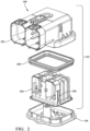
- FIG. 2 shows an exploded view of the sealed connector assembly 100.
- the first connector housing 102 includes an outer portion 202 and an inner portion 204 that may be disposed within the outer portion 202.
- the inner portion 204 defines one or more flexible arms 206 that releasably secure the inner portion 204 within the outer portion 202.
- the first connector housing 102 also includes a connector housing seal in the form of a compliant perimeter seal 208 that is disposed between the outer portion 202 and the inner portion 204 of the first connector housing 102.
- the perimeter seal 208 is formed of a compliant elastomeric material, such as an oil-bleeding silicone rubber, e.g., Dow SILASTIC ® 9201-50-LSR.
- the perimeter seal 208 has a seal side wall 302, a seal end wall 304 extending from a first end of the seal side wall 302 in a first direction, and a seal lip 306 extending from a second end of the seal side wall 302 in a second direction opposite the first direction.
- the seal side wall 302 also defines a sealing rib 308 around the circumference of the perimeter seal 208.
- the perimeter seal 208 in the illustrated example includes a pair of the sealing rib 308.
- the seal end wall 304 defines a groove 310.
- an end segment 506 of a perimeter wall 502 of the outer portion 202 defines a support rib 510 that is received within the groove 310.
- FIG. 4 shows an end cross section view of the sealed connector assembly 100 with the second connector housing 104 in a fully mated condition with the first connector housing 102.
- the seal lip 306 of the perimeter seal 208 is secured between the inner portion 204 and the outer portion 202 of the first connector housing 102.
- the second connector housing 104 is inserted into the first connector housing 102 such that a header wall 402 of the second connector housing 104 is disposed between the perimeter seal 208 and an outer wall 404 of the outer portion 202 of the first connector housing 102.
- the flexible arms 206 of the inner portion 204 of the first connector housing 102 engage a ridge 406 of the outer portion 202 to releasably secure the inner portion 204 within the outer portion 202.
- FIG. 5 shows a close-up view of the cross section view of FIG. 4 highlighting the interface between the perimeter seal 208 and the first and second connector housings 102, 104.
- the outer portion 202 has an L-shaped perimeter wall 502 which defines a side segment 504 and an end segment 506.
- the seal side wall 302 abuts the side segment 504 and the seal end wall 304 abuts the end segment 506.
- the seal lip 306 overlays an end of the side segment 504 of the perimeter wall 502.
- the inner portion 204 is disposed inside the perimeter wall 502 and has a connector lip 508 that overlies the seal lip 306 and the end of the side segment 504,
- the connector lip 508 compresses the seal lip 306 between the connector lip 508 and the end of the side segment 504, thereby retaining the perimeter seal 208 to the outer portion 202 of the first connector housing 102 and inhibiting movement and bunching of the perimeter seal 208 as the second connector housing 104 is mated with the first connector housing 102.
- the sealing ribs 308 are also resiliently compressed by the contact with the header wall 402. This compression of the sealing ribs 308 is configured to inhibit environmental contaminants, such as water, dust, or other foreign materials, from entering the interior of the first and second connector housings 102, 104.
- the seal lip 306 is curved and an apex of the seal lip 306 is thicker than the ends of the seal lip 306.
- the support rib 510 of the perimeter wall 502 is received within the groove 310 of the perimeter seal 208.
- the groove 310 and the support rib 510 may extend around the perimeter of the seal end wall 304 and the end segment 506 of the perimeter wall 502.
- the groove 310 and the support rib 510 cooperate to further inhibit movement and bunching of the perimeter seal 208 as the second connector housing 104 is mated with the first connector housing 102.
- FIG. 5 also shows that, when fully mated, a header wall 402 of the second connector housing 104 is in compressive contact with the sealing rib 308.
- the compressive contact of the header wall 402 with the sealing rib 308 and the seal end wall 304 is configured to further inhibit environmental contaminants from entering the interior of the first and second connector housings 102, 104.
- the header wall 402 may also be in compressive contact with the seal end wall 304 of the perimeter seal 208 to provide enhanced protection from intrusion of environmental contaminants into the interior of the first and second connector housings 102, 104.
- Other embodiments may be envisioned in which the header wall 402 of the second connector housing 104 is in compressive contact with the sealing rib 308 but not the seal end wall 304.
- the perimeter seal 208 is configured so that it does not "bunch up" as the second connector housing 104 is inserted within the first connector housing 102 when the perimeter seal 208 and the first and second connector housings 102, 104 are in nominal dimensional conditions.
- the sealed connector assembly 100 presented herein has been found to resist bunching of the perimeter seal 208 between the first and second connector housings 102, 104 even in maximum material conditions. This provides lower engagement forces when mating the first and second connector housings 102, 104 that enhances ergonomic performance of the sealed connector assembly 100.
- the sealed connector assembly 100 has also been found to be less susceptible to bunching of the perimeter seal 208 due to variation in the material forming the perimeter seal 208, e.g., variations in oil bleed sealing materials.
- FIG. 6 shows a flow chart of a method of manufacturing a sealed connector assembly including the following steps:
- a compliant perimeter seal is inserted within an outer portion of a connector housing.
- this step includes inserting a compliant perimeter seal 208 within an outer portion 202 of a connector housing 102.
- the perimeter seal 208 has a seal side wall 302, a seal end wall 304 extending from a first end of the seal side wall 302 in a first direction, and a curved seal lip 306 extending from a second end of the seal side wall 302 in a second direction opposite the first direction.
- the outer portion 202 has a perimeter wall 502 defining a side segment 504 and an end segment 506.
- the seal side wall is abutted against the side segment. In some embodiments, this step includes abutting the seal side wall 302 against the side segment 504.
- the seal end wall is abutted against the end segment. In some embodiments, this step includes abutting the seal end wall 304 against the end segment 506.
- the seal lip is laid over an end of the side segment of the perimeter wall.
- this step includes overlaying the seal lip 306 over an end of the side segment 504 of the perimeter wall 502.
- an inner portion of the first connector housing is inserted within a perimeter wall of the outer portion.
- this step includes inserting an inner portion 204 of the connector housing 102 within a perimeter wall 502 of the outer portion 202.
- the inner portion 204 has a connector lip 508 that overlies the seal lip 306 and an end of the side segment 504 of the perimeter wall 502.
- the seal lip is captured between the connector lip and the end of the side segment of the perimeter wall.
- this step includes capturing the seal lip 306 between the connector lip 508 and the end of the side segment 504 of the perimeter wall 502 to retain the perimeter seal 208 to the connector housing 102.
- the inner portion is attached to the outer portion.
- this step includes removably attaching the inner portion 204 of the connector housing 102 to the outer portion 202 of the connector housing 102 using an attachment feature.
- the attachment feature is a flexible arm 206 defined by the inner portion 204 of the connector housing 102 that engages a ridge 406 on the outer portion 202.
- a support rib is inserted within a groove.
- the seal end wall 304 defines a groove 310, and the end segment 506 of the perimeter wall 502 defines a support rib 510.
- this step includes inserting the support rib 510 within the groove 310.
- a second connector housing 104 is inserted within the connector housing 102.
- the connector housing 102 is a first connector housing 102
- the seal side wall 302 defines a sealing rib 308.
- this step includes inserting a second connector housing 104 within the first connector housing 102.
- a portion of the second connector housing is placed in compressive contact with the sealing rib of the perimeter seal.
- the seal side wall 302 defines a sealing rib 308.
- this step includes placing a portion of the second connector housing 104 in compressive contact with the sealing rib 308 of the perimeter seal 208.
- the header wall 402 is in compressive contact with the sealing rib 308.
- the second connector housing is further inserted within the first connector housing.
- this step includes inserting the second connector housing 104 further within the first connector housing 102.
- a portion of the second connector housing is placed in compressive contact with the seal end wall.
- this step includes placing a portion of the second connector housing 104 in compressive contact with the seal end wall 304 of the perimeter seal 208.
- the header wall 402 is in compressive contact with the seal end wall 304.
- a sealed connector assembly including: a compliant perimeter seal having a seal side wall, a seal end wall extending from a first end of the seal side wall in a first direction, and a seal lip extending from a second end of the seal side wall in a second direction opposite the first direction; and a connector housing, further including: an outer portion having a perimeter wall which defines a side segment and an end segment, the seal side wall abutting the side segment and the seal end wall abutting the end segment and the seal lip overlaying at least a portion of an end of the side segment of the perimeter wall, and an inner portion disposed inside the perimeter wall, the inner portion having a connector lip that overlies at least a portion of the seal lip and at least a portion of an end of the side segment of the perimeter wall.
- the sealed connector system of the preceding paragraph can optionally include, additionally and/or alternatively any, one or more of the following features, configurations and/or additional components.
- the techniques described herein relate to a sealed connector assembly, wherein the seal end wall defines a groove, and the end segment of the perimeter wall defines a support rib received within the groove.
- the techniques described herein relate to a sealed connector assembly, wherein the connector lip and the end of the side segment of the perimeter wall are in compressive contact with the seal lip.
- the techniques described herein relate to a sealed connector assembly, wherein the perimeter wall is L-shaped.
- the techniques described herein relate to a sealed connector assembly, wherein the inner portion of the connector housing is removably attached to the outer portion by an attachment feature.
- the techniques described herein relate to a sealed connector assembly, wherein the attachment feature is a flexible arm defined by the inner portion of the connector housing that engages a ridge on the outer portion.
- the techniques described herein relate to a sealed connector assembly, wherein the seal side wall defines a sealing rib.
- the techniques described herein relate to a sealed connector assembly, wherein the connector housing is a first connector housing, wherein the sealed connector assembly further includes a second connector housing configured to be received in the first connector housing, and wherein the second connector housing is in compressive contact with the sealing rib of the perimeter seal.
- the techniques described herein relate to a sealed connector assembly, wherein the second connector housing is in compressive contact with the seal end wall.
- the techniques described herein relate to a sealed connector assembly, wherein the perimeter seal is formed of a silicone-based rubber material, the first connector housing is formed of a polymeric material, and the second connector housing is formed of a metallic material.
- the techniques described herein relate to a sealed connector assembly, wherein the first connector housing is configured to contain a plurality of electrical terminals, and the second connector housing is configured to contain a plurality of mating electrical terminals.
- the techniques described herein relate to a sealed connector assembly, wherein the seal end wall is generally flat on one side and extends substantially perpendicularly from the seal side wall.
- the techniques described herein relate to a sealed connector assembly, wherein the seal lip curved.
- the techniques described herein relate to a sealed connector assembly, wherein an apex of the seal lip is thicker than ends of the seal lip and wherein the seal end wall is thicker than the seal lip.
- the techniques described herein relate to a method of manufacturing a sealed connector assembly, including: inserting a compliant perimeter seal within an outer portion of a first connector housing, the perimeter seal having a seal side wall, a seal end wall extending from a first end of the seal side wall in a first direction, and a curved seal lip extending from a second end of the seal side wall in a second direction opposite the first direction, the outer portion having a perimeter wall defining a side segment and an end segment; abutting the seal side wall against the side segment; abutting the seal end wall against the end segment; overlaying the seal lip over an end of the side segment of the perimeter wall; and inserting an inner portion of the first connector housing within a perimeter wall of the outer portion, the inner portion having a connector lip that overlies the seal lip and an end of the side segment of the perimeter wall; capturing the seal lip between the connector lip and the end of the side segment of the perimeter wall to retain the perimeter seal to the first connector housing.
- the method of the preceding paragraph can optionally include, additionally and/or alternatively any, one or more of the following features, configurations and/or additional components.
- the techniques described herein relate to a method, further including: removably attaching the inner portion of the connector housing to the outer portion using an attachment feature.
- the techniques described herein relate to a method, wherein the attachment feature is a flexible arm defined by the inner portion of the connector housing that engages a ridge on the outer portion.
- the techniques described herein relate to a method, wherein the seal end wall defines a groove, and the end segment of the perimeter wall defines a support rib, wherein the method additionally includes inserting the support rib within the groove.
- the techniques described herein relate to a method, wherein the connector housing is a first connector housing, wherein the seal side wall defines a sealing rib, and wherein the method additionally includes: inserting a second connector housing within the first connector housing and placing a portion of the second connector housing in compressive contact with the sealing rib of the perimeter seal.
- the techniques described herein relate to a method, wherein the method additionally includes further inserting the second connector housing within the first connector housing and placing a portion of the second connector housing in compressive contact with the seal end wall.
- 'one or more' includes a function being performed by one element, a function being performed by more than one element, e.g., in a distributed fashion, several functions being performed by one element, several functions being performed by several elements, or any combination of the above.
- first, second, etc. are, in some instances, used herein to describe various elements, these elements should not be limited by these terms. These terms are only used to distinguish one element from another.
- a first contact could be termed a second contact, and, similarly, a second contact could be termed a first contact, without departing from the scope of the various described embodiments.
- the first contact and the second contact are both contacts, but they are not the same contact.
- the term “if' is, optionally, construed to mean “when” or “upon” or “in response to determining” or “in response to detecting,” depending on the context.
- the phrase “if it is determined” or “if [a stated condition or event] is detected” is, optionally, construed to mean “upon determining” or “in response to determining” or “upon detecting [the stated condition or event]” or “in response to detecting [the stated condition or event],” depending on the context.
Landscapes
- Connector Housings Or Holding Contact Members (AREA)
Abstract
A sealed connector assembly may include a compliant perimeter seal having a seal side wall, a seal end wall extending from a first end of the seal side wall in a first direction, and a seal lip extending from a second end of the seal side wall in a second direction opposite the first direction. The seal side wall defines a sealing rib. The sealed connector assembly may include a connector housing, further including an outer portion having a perimeter wall with a side segment and an end segment. The seal side wall abuts the side segment, and the seal end wall abuts the end segment. The seal lip overlays an end of the side segment of the perimeter wall. An inner portion disposed inside the perimeter wall has a connector lip that overlies the seal lip and an end of the side segment of the perimeter wall.
Description
- This application claims the benefit of and priority to
U.S. Provisional Application 63/471,835, titled "Sealed Connector Assembly with Combination Connector Seal", filed June 8, 2023 - This disclosure is directed to a sealed connector assembly, particularly to a sealed connector assembly with a combination connector seal suited for use with automotive electrical connectors.
- Existing sealed connector assemblies are prone to causing variations in engagement force of the connector system due to small variations in the connector seal gap and/or the seal's material characteristics, especially oil bleed materials. Current seals used in sealed connector assemblies are also susceptible to bunching, pinching, and/or rolling when the separate connector housings of the connector assembly are mated together.
- Previous approaches to sealed connector assemblies have typically involved utilizing various types of seals and housings to prevent the ingress of contaminants and moisture into the connector interface. These approaches have included the use of O-rings, gaskets, and other sealing elements to create a barrier between the connector components and the external environment.
- While these traditional sealing methods have been effective to some extent, they often require complex assembly processes and may not provide a completely secure seal over time due to wear and degradation of the sealing materials.
- In some instances, connector housings have been designed with integrated sealing features to improve the overall sealing performance of the assembly. These integrated seals have been implemented to create a more robust barrier against environmental factors and to enhance the reliability of the connector interface. However, these integrated seals have typically been limited in their design and functionality, often lacking the flexibility and adaptability needed to accommodate variations in connector configurations and environmental conditions.
- Additionally, efforts have been made to develop connector assemblies with improved sealing capabilities by optimizing the interaction between the seal and the housing components. These efforts have focused on enhancing the sealing effectiveness of the connector assembly by ensuring proper alignment and engagement of the seal with the housing elements. Despite these advancements, challenges remain in achieving a sealed connector assembly that offers both reliable sealing performance and ease of assembly. However, none of these approaches have provided a comprehensive solution that combines the features described in this disclosure.
- In some aspects, the techniques described herein relate to a sealed connector assembly, including: a compliant perimeter seal having a seal side wall, a seal end wall extending from a first end of the seal side wall in a first direction, and a seal lip extending from a second end of the seal side wall in a second direction opposite the first direction; and a connector housing, further including: an outer portion having a perimeter wall which defines a side segment and an end segment, the seal side wall abutting the side segment and the seal end wall abutting the end segment and the seal lip overlaying at least a portion of an end of the side segment of the perimeter wall, and an inner portion disposed inside the perimeter wall, the inner portion having a connector lip that overlies at least a portion of the seal lip and at least a portion of an end of the side segment of the perimeter wall.
- In some aspects, the techniques described herein relate to a method of manufacturing a sealed connector assembly, including: inserting a compliant perimeter seal within an outer portion of a first connector housing, the perimeter seal having a seal side wall, a seal end wall extending from a first end of the seal side wall in a first direction, and a curved seal lip extending from a second end of the seal side wall in a second direction opposite the first direction, the outer portion having a perimeter wall defining a side segment and an end segment; abutting the seal side wall against the side segment; abutting the seal end wall against the end segment; overlaying the seal lip over an end of the side segment of the perimeter wall; and inserting an inner portion of the first connector housing within a perimeter wall of the outer portion, the inner portion having a connector lip that overlies the seal lip and an end of the side segment of the perimeter wall; capturing the seal lip between the connector lip and the end of the side segment of the perimeter wall to retain the perimeter seal to the first connector housing.
- Embodiments of the present invention will now be described by way of example with reference to the accompanying drawings, in which:
-
FIG. 1 is an isometric view of a sealed connector assembly according to some embodiments. -
FIG. 2 is an exploded view of the sealed connector assembly ofFIG. 1 according to some embodiments. -
FIG. 3A is an isolated isometric view of a connector housing seal of the sealed connector assembly ofFIG. 1 according to some embodiments. -
FIG. 3B is a cross-section view of the connector housing seal ofFIG. 3A according to some embodiments. -
FIG. 3C is a close-up view ofFIG. 3B according to some embodiments. -
FIG. 4 is a cross section end view of the sealed connector assembly ofFIG. 1 according to some embodiments. -
FIG. 5 is a close up view of the cross section end view ofFIG. 4 according to some embodiments. -
FIG. 6 is a flow chart of a method of manufacturing a sealed connector assembly according to some embodiments. -
FIG. 1 shows a non-limiting example of a sealedconnector assembly 100. While the example presented herein is directed to a sealed electrical connector assembly, alternative embodiments of the connector may be envisioned that are configured to interconnect fiber optic cables, pneumatic tubes, hydraulic tubes, or a hybrid sealed connector having a combination of any of these types of conductors. As shown inFIG. 1 , the sealedconnector assembly 100 includes afirst connector housing 102 which is configured to be mated with asecond connector housing 104. In the illustrated example, the first connector housing is made of a polymeric material, such as polyamide (NYLON) or polybutylene terephthalate (PBT), the polymeric material may or may not be glass-filled. In the illustrated example, thesecond connector housing 104 is made of a metallic material, such as aluminum and may integrally formed with another component, such as a battery pack of an electric vehicle. Other embodiments of the sealedconnector assembly 100 may be envisioned in which the first andsecond connector housings -
FIG. 2 shows an exploded view of the sealedconnector assembly 100. Thefirst connector housing 102 includes anouter portion 202 and aninner portion 204 that may be disposed within theouter portion 202. Theinner portion 204 defines one or moreflexible arms 206 that releasably secure theinner portion 204 within theouter portion 202. Thefirst connector housing 102 also includes a connector housing seal in the form of acompliant perimeter seal 208 that is disposed between theouter portion 202 and theinner portion 204 of thefirst connector housing 102. Theperimeter seal 208 is formed of a compliant elastomeric material, such as an oil-bleeding silicone rubber, e.g., Dow SILASTIC® 9201-50-LSR. - As shown in
FIGs. 3A and 3B , theperimeter seal 208 has aseal side wall 302, aseal end wall 304 extending from a first end of theseal side wall 302 in a first direction, and aseal lip 306 extending from a second end of theseal side wall 302 in a second direction opposite the first direction. Theseal side wall 302 also defines a sealingrib 308 around the circumference of theperimeter seal 208. Theperimeter seal 208 in the illustrated example includes a pair of the sealingrib 308. As best shown inFIG. 3C , theseal end wall 304 defines agroove 310. As shown inFIG. 5 , anend segment 506 of aperimeter wall 502 of theouter portion 202 defines asupport rib 510 that is received within thegroove 310. -
FIG. 4 shows an end cross section view of the sealedconnector assembly 100 with thesecond connector housing 104 in a fully mated condition with thefirst connector housing 102. As can be seen inFIG. 4 , theseal lip 306 of theperimeter seal 208 is secured between theinner portion 204 and theouter portion 202 of thefirst connector housing 102. Thesecond connector housing 104 is inserted into thefirst connector housing 102 such that aheader wall 402 of thesecond connector housing 104 is disposed between theperimeter seal 208 and anouter wall 404 of theouter portion 202 of thefirst connector housing 102. As can further be seen inFIG. 4 , theflexible arms 206 of theinner portion 204 of thefirst connector housing 102 engage aridge 406 of theouter portion 202 to releasably secure theinner portion 204 within theouter portion 202. -
FIG. 5 shows a close-up view of the cross section view ofFIG. 4 highlighting the interface between theperimeter seal 208 and the first andsecond connector housings FIG. 5 , theouter portion 202 has an L-shaped perimeter wall 502 which defines aside segment 504 and anend segment 506. Theseal side wall 302 abuts theside segment 504 and theseal end wall 304 abuts theend segment 506. Theseal lip 306 overlays an end of theside segment 504 of theperimeter wall 502. Theinner portion 204 is disposed inside theperimeter wall 502 and has aconnector lip 508 that overlies theseal lip 306 and the end of theside segment 504, Theconnector lip 508 compresses theseal lip 306 between theconnector lip 508 and the end of theside segment 504, thereby retaining theperimeter seal 208 to theouter portion 202 of thefirst connector housing 102 and inhibiting movement and bunching of theperimeter seal 208 as thesecond connector housing 104 is mated with thefirst connector housing 102. The sealingribs 308 are also resiliently compressed by the contact with theheader wall 402. This compression of thesealing ribs 308 is configured to inhibit environmental contaminants, such as water, dust, or other foreign materials, from entering the interior of the first andsecond connector housings - As shown in
FIG. 5 , theseal lip 306 is curved and an apex of theseal lip 306 is thicker than the ends of theseal lip 306. - As further shown in
FIG. 5 , thesupport rib 510 of theperimeter wall 502 is received within thegroove 310 of theperimeter seal 208. Thegroove 310 and thesupport rib 510 may extend around the perimeter of theseal end wall 304 and theend segment 506 of theperimeter wall 502. Thegroove 310 and thesupport rib 510 cooperate to further inhibit movement and bunching of theperimeter seal 208 as thesecond connector housing 104 is mated with thefirst connector housing 102. -
FIG. 5 also shows that, when fully mated, aheader wall 402 of thesecond connector housing 104 is in compressive contact with the sealingrib 308. The compressive contact of theheader wall 402 with the sealingrib 308 and theseal end wall 304 is configured to further inhibit environmental contaminants from entering the interior of the first andsecond connector housings header wall 402 may also be in compressive contact with theseal end wall 304 of theperimeter seal 208 to provide enhanced protection from intrusion of environmental contaminants into the interior of the first andsecond connector housings header wall 402 of thesecond connector housing 104 is in compressive contact with the sealingrib 308 but not theseal end wall 304. - The
perimeter seal 208 is configured so that it does not "bunch up" as thesecond connector housing 104 is inserted within thefirst connector housing 102 when theperimeter seal 208 and the first andsecond connector housings - The sealed
connector assembly 100 presented herein has been found to resist bunching of theperimeter seal 208 between the first andsecond connector housings second connector housings connector assembly 100. The sealedconnector assembly 100 has also been found to be less susceptible to bunching of theperimeter seal 208 due to variation in the material forming theperimeter seal 208, e.g., variations in oil bleed sealing materials. -
FIG. 6 shows a flow chart of a method of manufacturing a sealed connector assembly including the following steps: - At
STEP 602, a compliant perimeter seal is inserted within an outer portion of a connector housing. In some embodiments, this step includes inserting acompliant perimeter seal 208 within anouter portion 202 of aconnector housing 102. Theperimeter seal 208 has aseal side wall 302, aseal end wall 304 extending from a first end of theseal side wall 302 in a first direction, and acurved seal lip 306 extending from a second end of theseal side wall 302 in a second direction opposite the first direction. Theouter portion 202 has aperimeter wall 502 defining aside segment 504 and anend segment 506. - At
STEP 604, the seal side wall is abutted against the side segment. In some embodiments, this step includes abutting theseal side wall 302 against theside segment 504. - At
STEP 606, the seal end wall is abutted against the end segment. In some embodiments, this step includes abutting theseal end wall 304 against theend segment 506. - At
STEP 608, the seal lip is laid over an end of the side segment of the perimeter wall. In some embodiments, this step includes overlaying theseal lip 306 over an end of theside segment 504 of theperimeter wall 502. - At
STEP 610, an inner portion of the first connector housing is inserted within a perimeter wall of the outer portion. In some embodiments, this step includes inserting aninner portion 204 of theconnector housing 102 within aperimeter wall 502 of theouter portion 202. Theinner portion 204 has aconnector lip 508 that overlies theseal lip 306 and an end of theside segment 504 of theperimeter wall 502. - At
STEP 612, the seal lip is captured between the connector lip and the end of the side segment of the perimeter wall. In some embodiments, this step includes capturing theseal lip 306 between theconnector lip 508 and the end of theside segment 504 of theperimeter wall 502 to retain theperimeter seal 208 to theconnector housing 102. - At
STEP 614, the inner portion is attached to the outer portion. In some embodiments, this step includes removably attaching theinner portion 204 of theconnector housing 102 to theouter portion 202 of theconnector housing 102 using an attachment feature. In some embodiments, the attachment feature is aflexible arm 206 defined by theinner portion 204 of theconnector housing 102 that engages aridge 406 on theouter portion 202. - At
STEP 616, a support rib is inserted within a groove. In some embodiments, theseal end wall 304 defines agroove 310, and theend segment 506 of theperimeter wall 502 defines asupport rib 510. In some embodiments, this step includes inserting thesupport rib 510 within thegroove 310. - At
STEP 618, asecond connector housing 104 is inserted within theconnector housing 102. In some embodiments, theconnector housing 102 is afirst connector housing 102, and theseal side wall 302 defines a sealingrib 308. In some embodiments, this step includes inserting asecond connector housing 104 within thefirst connector housing 102. - At
STEP 620, a portion of the second connector housing is placed in compressive contact with the sealing rib of the perimeter seal. In some embodiments, theseal side wall 302 defines a sealingrib 308. In some embodiments, this step includes placing a portion of thesecond connector housing 104 in compressive contact with the sealingrib 308 of theperimeter seal 208. In some embodiments, theheader wall 402 is in compressive contact with the sealingrib 308. - At
STEP 622, the second connector housing is further inserted within the first connector housing. In some embodiments, this step includes inserting thesecond connector housing 104 further within thefirst connector housing 102. - At
STEP 624, a portion of the second connector housing is placed in compressive contact with the seal end wall. In some embodiments, this step includes placing a portion of thesecond connector housing 104 in compressive contact with theseal end wall 304 of theperimeter seal 208. In some embodiments, theheader wall 402 is in compressive contact with theseal end wall 304. - The following are non-exclusive descriptions of possible embodiments of the present invention.
- In some aspects, the techniques described herein relate to a sealed connector assembly, including: a compliant perimeter seal having a seal side wall, a seal end wall extending from a first end of the seal side wall in a first direction, and a seal lip extending from a second end of the seal side wall in a second direction opposite the first direction; and a connector housing, further including: an outer portion having a perimeter wall which defines a side segment and an end segment, the seal side wall abutting the side segment and the seal end wall abutting the end segment and the seal lip overlaying at least a portion of an end of the side segment of the perimeter wall, and an inner portion disposed inside the perimeter wall, the inner portion having a connector lip that overlies at least a portion of the seal lip and at least a portion of an end of the side segment of the perimeter wall.
- The sealed connector system of the preceding paragraph can optionally include, additionally and/or alternatively any, one or more of the following features, configurations and/or additional components.
- In some aspects, the techniques described herein relate to a sealed connector assembly, wherein the seal end wall defines a groove, and the end segment of the perimeter wall defines a support rib received within the groove.
- In some aspects, the techniques described herein relate to a sealed connector assembly, wherein the connector lip and the end of the side segment of the perimeter wall are in compressive contact with the seal lip.
- In some aspects, the techniques described herein relate to a sealed connector assembly, wherein the perimeter wall is L-shaped.
- In some aspects, the techniques described herein relate to a sealed connector assembly, wherein the inner portion of the connector housing is removably attached to the outer portion by an attachment feature.
- In some aspects, the techniques described herein relate to a sealed connector assembly, wherein the attachment feature is a flexible arm defined by the inner portion of the connector housing that engages a ridge on the outer portion.
- In some aspects, the techniques described herein relate to a sealed connector assembly, wherein the seal side wall defines a sealing rib.
- In some aspects, the techniques described herein relate to a sealed connector assembly, wherein the connector housing is a first connector housing, wherein the sealed connector assembly further includes a second connector housing configured to be received in the first connector housing, and wherein the second connector housing is in compressive contact with the sealing rib of the perimeter seal.
- In some aspects, the techniques described herein relate to a sealed connector assembly, wherein the second connector housing is in compressive contact with the seal end wall.
- In some aspects, the techniques described herein relate to a sealed connector assembly, wherein the perimeter seal is formed of a silicone-based rubber material, the first connector housing is formed of a polymeric material, and the second connector housing is formed of a metallic material.
- In some aspects, the techniques described herein relate to a sealed connector assembly, wherein the first connector housing is configured to contain a plurality of electrical terminals, and the second connector housing is configured to contain a plurality of mating electrical terminals.
- In some aspects, the techniques described herein relate to a sealed connector assembly, wherein the seal end wall is generally flat on one side and extends substantially perpendicularly from the seal side wall.
- In some aspects, the techniques described herein relate to a sealed connector assembly, wherein the seal lip curved.
- In some aspects, the techniques described herein relate to a sealed connector assembly, wherein an apex of the seal lip is thicker than ends of the seal lip and wherein the seal end wall is thicker than the seal lip.
- In some aspects, the techniques described herein relate to a method of manufacturing a sealed connector assembly, including: inserting a compliant perimeter seal within an outer portion of a first connector housing, the perimeter seal having a seal side wall, a seal end wall extending from a first end of the seal side wall in a first direction, and a curved seal lip extending from a second end of the seal side wall in a second direction opposite the first direction, the outer portion having a perimeter wall defining a side segment and an end segment; abutting the seal side wall against the side segment; abutting the seal end wall against the end segment; overlaying the seal lip over an end of the side segment of the perimeter wall; and inserting an inner portion of the first connector housing within a perimeter wall of the outer portion, the inner portion having a connector lip that overlies the seal lip and an end of the side segment of the perimeter wall; capturing the seal lip between the connector lip and the end of the side segment of the perimeter wall to retain the perimeter seal to the first connector housing.
- The method of the preceding paragraph can optionally include, additionally and/or alternatively any, one or more of the following features, configurations and/or additional components.
- In some aspects, the techniques described herein relate to a method, further including: removably attaching the inner portion of the connector housing to the outer portion using an attachment feature.
- In some aspects, the techniques described herein relate to a method, wherein the attachment feature is a flexible arm defined by the inner portion of the connector housing that engages a ridge on the outer portion.
- In some aspects, the techniques described herein relate to a method, wherein the seal end wall defines a groove, and the end segment of the perimeter wall defines a support rib, wherein the method additionally includes inserting the support rib within the groove.
- In some aspects, the techniques described herein relate to a method, wherein the connector housing is a first connector housing, wherein the seal side wall defines a sealing rib, and wherein the method additionally includes: inserting a second connector housing within the first connector housing and placing a portion of the second connector housing in compressive contact with the sealing rib of the perimeter seal.
- In some aspects, the techniques described herein relate to a method, wherein the method additionally includes further inserting the second connector housing within the first connector housing and placing a portion of the second connector housing in compressive contact with the seal end wall.
- While the invention has been described with reference to an exemplary embodiment(s), it will be understood by those skilled in the art that various changes may be made, and equivalents may be substituted for elements thereof without departing from the scope of the invention. In addition, many modifications may be made to adapt a particular situation or material to the teachings of the invention without departing from the essential scope thereof. Therefore, it is intended that the invention is not limited to the disclosed embodiment(s), but that the invention will include all embodiments falling within the scope of the appended claims.
- As used herein, 'one or more' includes a function being performed by one element, a function being performed by more than one element, e.g., in a distributed fashion, several functions being performed by one element, several functions being performed by several elements, or any combination of the above.
- It will also be understood that, although the terms first, second, etc. are, in some instances, used herein to describe various elements, these elements should not be limited by these terms. These terms are only used to distinguish one element from another. For example, a first contact could be termed a second contact, and, similarly, a second contact could be termed a first contact, without departing from the scope of the various described embodiments. The first contact and the second contact are both contacts, but they are not the same contact.
- The terminology used in the description of the various described embodiments herein is for the purpose of describing particular embodiments only and is not intended to be limiting. As used in the description of the various described embodiments and the appended claims, the singular forms "a", "an", and "the" are intended to include the plural forms as well, unless the context clearly indicates otherwise. It will also be understood that the term "and/or" as used herein refers to and encompasses any and all possible combinations of one or more of the associated listed items. It will be further understood that the terms "includes," "including," "comprises," and/or "comprising," when used in this specification, specify the presence of stated features, integers, steps, operations, elements, and/or components, but do not preclude the presence or addition of one or more other features, integers, steps, operations, elements, components, and/or groups thereof.
- As used herein, the term "if' is, optionally, construed to mean "when" or "upon" or "in response to determining" or "in response to detecting," depending on the context. Similarly, the phrase "if it is determined" or "if [a stated condition or event] is detected" is, optionally, construed to mean "upon determining" or "in response to determining" or "upon detecting [the stated condition or event]" or "in response to detecting [the stated condition or event]," depending on the context.
- Additionally, while terms of ordinance or orientation may be used herein these elements should not be limited by these terms. All terms of ordinance or orientation, unless stated otherwise, are used for purposes distinguishing one element from another, and do not denote any particular order, order of operations, direction or orientation unless stated otherwise.
Claims (15)
- A sealed connector assembly (100), comprising:a compliant perimeter seal (208) having a seal side wall (302), a seal end wall (304) extending from a first end of the seal side wall (302) in a first direction, and a seal lip (306) extending from a second end of the seal side wall (302) in a second direction opposite the first direction; anda connector housing (102), further comprising:an outer portion (202) having a perimeter wall (502) which defines a side segment (504) and an end segment (506), the seal side wall (302) abutting the side segment (504) and the seal end wall (304) abutting the end segment (506) and the seal lip (306) overlaying at least a portion of an end of the side segment (504) of the perimeter wall (502), andan inner portion (204) disposed inside the perimeter wall (502), the inner portion (204) having a connector lip (508) that overlies at least a portion of the seal lip (306) and at least a portion of an end of the side segment (504) of the perimeter wall (502).
- The sealed connector assembly (100) according to claim 1, wherein the seal end wall (304) defines a groove (310), and the end segment (506) of the perimeter wall (502) defines a support rib (510) received within the groove (310).
- The sealed connector assembly (100) according to claim 1 or 2, wherein the connector lip (508) and the end of the side segment (504) of the perimeter wall (502) are in compressive contact with the seal lip (306).
- The sealed connector assembly (100) according to any one of the preceding claims, wherein the perimeter wall (502) is L-shaped.
- The sealed connector assembly (100) according to any one of the preceding claims, wherein the inner portion (204) of the connector housing (102) is removably attached to the outer portion (202) by an attachment feature.
- The sealed connector assembly (100) according to claim 5, wherein the attachment feature is a flexible arm defined by the inner portion (204) of the connector housing (102) that engages a ridge (406) on the outer portion (202).
- The sealed connector assembly (100) according to any one of the preceding claims, wherein the seal side wall (302) defines a sealing rib (308).
- The sealed connector assembly (100) according to claim 7, wherein the connector housing (102) is a first connector housing (102), wherein the sealed connector assembly (100) further comprises a second connector housing (104) configured to be received in the first connector housing (102), and wherein the second connector housing (104) is in compressive contact with the sealing rib (308) of the perimeter seal (208).
- The sealed connector assembly (100) according to claim 8, wherein the second connector housing (104) is in compressive contact with the seal end wall (304).
- The sealed connector assembly (100) according to any one of the preceding claims, wherein the seal end wall (304) is generally flat on one side and extends substantially perpendicularly from the seal side wall (302) and wherein the seal lip (306) curved.
- The sealed connector assembly (100) according to claim 10, wherein an apex of the seal lip (306) is thicker than ends of the seal lip (306) and wherein the seal end wall (304) is thicker than the seal lip (306).
- A method of manufacturing a sealed connector assembly (100), comprising:inserting a compliant perimeter seal (208) within an outer portion (202) of a first connector housing (102), the perimeter seal (208) having a seal side wall (302), a seal end wall (304) extending from a first end of the seal side wall (302) in a first direction, and a curved seal lip (306) extending from a second end of the seal side wall (302) in a second direction opposite the first direction, the outer portion (202) having a perimeter wall (502) defining a side segment (504) and an end segment (506);abutting the seal side wall (302) against the side segment (504);abutting the seal end wall (304) against the end segment (506);overlaying the seal lip (306) over an end of the side segment (504) of the perimeter wall (502);inserting an inner portion (204) of the first connector housing (102) within a perimeter wall (502) of the outer portion (202), the inner portion (204) having a connector lip (508) that overlies the seal lip (306) and an end of the side segment (504) of the perimeter wall (502); andcapturing the seal lip (306) between the connector lip (508) and the end of the side segment (504) of the perimeter wall (502) to retain the perimeter seal (208) to the first connector housing (102).
- The method according to claim 12, wherein the seal end wall (304) defines a groove (310), and the end segment (506) of the perimeter wall (502) defines a support rib (510) and wherein the method further comprises:removably attaching the inner portion (204) of the first connector housing (102) to the outer portion (202) using an attachment feature; andinserting the support rib (510) within the groove (310).
- The method according to claim 12 or 13, wherein the seal side wall (302) defines a sealing rib (308) and wherein the method additionally comprises:inserting a second connector housing (104) within the first connector housing (102); andplacing a portion of the second connector housing (104) in compressive contact with the sealing rib (308) of the perimeter seal (208).
- The method of claim 14, wherein the method additionally comprises:further inserting the second connector housing (104) within the first connector housing (102); andplacing a portion of the second connector housing (104) in compressive contact with the seal end wall (304).
Applications Claiming Priority (2)
| Application Number | Priority Date | Filing Date | Title |
|---|---|---|---|
| US202363471835P | 2023-06-08 | 2023-06-08 | |
| US18/734,265 US20240413568A1 (en) | 2023-06-08 | 2024-06-05 | Sealed connector assembly with combination connector seal |
Publications (1)
| Publication Number | Publication Date |
|---|---|
| EP4475352A1 true EP4475352A1 (en) | 2024-12-11 |
Family
ID=91435084
Family Applications (1)
| Application Number | Title | Priority Date | Filing Date |
|---|---|---|---|
| EP24180630.6A Pending EP4475352A1 (en) | 2023-06-08 | 2024-06-06 | Sealed connector assembly with combination connector seal |
Country Status (2)
| Country | Link |
|---|---|
| US (1) | US20240413568A1 (en) |
| EP (1) | EP4475352A1 (en) |
Citations (3)
| Publication number | Priority date | Publication date | Assignee | Title |
|---|---|---|---|---|
| JP2008192459A (en) * | 2007-02-05 | 2008-08-21 | Fci Connectors Singapore Pte Ltd | Electric connector |
| US20150372413A1 (en) * | 2014-06-24 | 2015-12-24 | Japan Aviation Electronics Industry, Limited | Waterproof connector |
| CN110998980A (en) * | 2017-08-01 | 2020-04-10 | 德尔福技术有限公司 | Connector assembly and seal |
-
2024
- 2024-06-05 US US18/734,265 patent/US20240413568A1/en active Pending
- 2024-06-06 EP EP24180630.6A patent/EP4475352A1/en active Pending
Patent Citations (3)
| Publication number | Priority date | Publication date | Assignee | Title |
|---|---|---|---|---|
| JP2008192459A (en) * | 2007-02-05 | 2008-08-21 | Fci Connectors Singapore Pte Ltd | Electric connector |
| US20150372413A1 (en) * | 2014-06-24 | 2015-12-24 | Japan Aviation Electronics Industry, Limited | Waterproof connector |
| CN110998980A (en) * | 2017-08-01 | 2020-04-10 | 德尔福技术有限公司 | Connector assembly and seal |
Also Published As
| Publication number | Publication date |
|---|---|
| US20240413568A1 (en) | 2024-12-12 |
Similar Documents
| Publication | Publication Date | Title |
|---|---|---|
| US9847597B2 (en) | Electrical connector with sealing structure | |
| US11848514B2 (en) | Elastomer seal spring | |
| US7229303B2 (en) | Environmentally sealed connector with blind mating capability | |
| CN102237597B (en) | Connector and waterproof connector | |
| EP2930795A1 (en) | Sealed connector with an extended seal sleeve and an anti-water pooling retainer | |
| EP0646991B1 (en) | Wire holder for a water-proof connector | |
| EP3413404A1 (en) | Sealed electrical connector assembly and wire seal | |
| US10777934B2 (en) | Electrical connector which accepts different seal configurations | |
| WO2017015285A1 (en) | Terminal fitting | |
| US20030032321A1 (en) | Sealed connector | |
| CN102099973A (en) | Waterproof connector | |
| US6783396B1 (en) | Airtight plug connector and terminal insert | |
| CN111384634B (en) | Connector with a locking member | |
| US20240413568A1 (en) | Sealed connector assembly with combination connector seal | |
| US11469539B2 (en) | Seals for a flat flexible conductor in an electrical connector assembly | |
| EP3419130B1 (en) | Wire harness assembly and seal retainer therefore | |
| US12244091B2 (en) | Electrical connector having a seal with a secondary terminal locking mechanism | |
| CN103765693A (en) | Connector and coating member used for the same | |
| US12500370B2 (en) | Connection device using connector | |
| US11450985B2 (en) | Connector with integrated seal retainer and secondary terminal lock | |
| CN108963560B (en) | Connector with a locking member | |
| EP4398426A1 (en) | Connector assembly with flexible lock and event driven wedge | |
| EP4343980A1 (en) | Electrical connector having a wire seal with a secondary terminal locking mechanism | |
| US12542396B2 (en) | Electrical connector wire seal assembly that is substantially rigid along a first axis | |
| US20220166160A1 (en) | Electrical connector and connector assembly |
Legal Events
| Date | Code | Title | Description |
|---|---|---|---|
| PUAI | Public reference made under article 153(3) epc to a published international application that has entered the european phase |
Free format text: ORIGINAL CODE: 0009012 |
|
| STAA | Information on the status of an ep patent application or granted ep patent |
Free format text: STATUS: THE APPLICATION HAS BEEN PUBLISHED |
|
| AK | Designated contracting states |
Kind code of ref document: A1 Designated state(s): AL AT BE BG CH CY CZ DE DK EE ES FI FR GB GR HR HU IE IS IT LI LT LU LV MC ME MK MT NL NO PL PT RO RS SE SI SK SM TR |
|
| STAA | Information on the status of an ep patent application or granted ep patent |
Free format text: STATUS: REQUEST FOR EXAMINATION WAS MADE |
|
| 17P | Request for examination filed |
Effective date: 20250117 |