EP4475313A1 - Electricity storage pack - Google Patents
Electricity storage pack Download PDFInfo
- Publication number
- EP4475313A1 EP4475313A1 EP23747039.8A EP23747039A EP4475313A1 EP 4475313 A1 EP4475313 A1 EP 4475313A1 EP 23747039 A EP23747039 A EP 23747039A EP 4475313 A1 EP4475313 A1 EP 4475313A1
- Authority
- EP
- European Patent Office
- Prior art keywords
- battery
- power storage
- hollow member
- pack
- case
- Prior art date
- Legal status (The legal status is an assumption and is not a legal conclusion. Google has not performed a legal analysis and makes no representation as to the accuracy of the status listed.)
- Pending
Links
- 230000005611 electricity Effects 0.000 title 1
- 229920005989 resin Polymers 0.000 claims abstract description 22
- 239000011347 resin Substances 0.000 claims abstract description 22
- 239000000945 filler Substances 0.000 claims abstract description 10
- 239000000463 material Substances 0.000 claims description 52
- 238000004382 potting Methods 0.000 description 49
- 239000007789 gas Substances 0.000 description 34
- 238000007789 sealing Methods 0.000 description 18
- 230000005856 abnormality Effects 0.000 description 13
- 230000002159 abnormal effect Effects 0.000 description 9
- 230000001681 protective effect Effects 0.000 description 7
- 230000002093 peripheral effect Effects 0.000 description 6
- HBBGRARXTFLTSG-UHFFFAOYSA-N Lithium ion Chemical compound [Li+] HBBGRARXTFLTSG-UHFFFAOYSA-N 0.000 description 4
- 239000000853 adhesive Substances 0.000 description 4
- 230000001070 adhesive effect Effects 0.000 description 4
- 238000006243 chemical reaction Methods 0.000 description 4
- 230000000052 comparative effect Effects 0.000 description 4
- 229910001416 lithium ion Inorganic materials 0.000 description 4
- -1 polyethylene Polymers 0.000 description 4
- 238000010586 diagram Methods 0.000 description 3
- 229910052751 metal Inorganic materials 0.000 description 3
- 239000002184 metal Substances 0.000 description 3
- 239000011255 nonaqueous electrolyte Substances 0.000 description 3
- PXHVJJICTQNCMI-UHFFFAOYSA-N Nickel Chemical compound [Ni] PXHVJJICTQNCMI-UHFFFAOYSA-N 0.000 description 2
- 239000004698 Polyethylene Substances 0.000 description 2
- 239000004743 Polypropylene Substances 0.000 description 2
- 239000003990 capacitor Substances 0.000 description 2
- 239000008151 electrolyte solution Substances 0.000 description 2
- 239000003822 epoxy resin Substances 0.000 description 2
- 238000005192 partition Methods 0.000 description 2
- 229920000647 polyepoxide Polymers 0.000 description 2
- 229920000573 polyethylene Polymers 0.000 description 2
- 229920001155 polypropylene Polymers 0.000 description 2
- 239000004800 polyvinyl chloride Substances 0.000 description 2
- 229920000915 polyvinyl chloride Polymers 0.000 description 2
- XLYOFNOQVPJJNP-UHFFFAOYSA-N water Substances O XLYOFNOQVPJJNP-UHFFFAOYSA-N 0.000 description 2
- UFHFLCQGNIYNRP-UHFFFAOYSA-N Hydrogen Chemical compound [H][H] UFHFLCQGNIYNRP-UHFFFAOYSA-N 0.000 description 1
- 239000004640 Melamine resin Substances 0.000 description 1
- 229920000877 Melamine resin Polymers 0.000 description 1
- 239000004793 Polystyrene Substances 0.000 description 1
- 239000011358 absorbing material Substances 0.000 description 1
- 238000010521 absorption reaction Methods 0.000 description 1
- 230000002411 adverse Effects 0.000 description 1
- WNROFYMDJYEPJX-UHFFFAOYSA-K aluminium hydroxide Chemical compound [OH-].[OH-].[OH-].[Al+3] WNROFYMDJYEPJX-UHFFFAOYSA-K 0.000 description 1
- 230000015572 biosynthetic process Effects 0.000 description 1
- 239000001257 hydrogen Substances 0.000 description 1
- 229910052739 hydrogen Inorganic materials 0.000 description 1
- 238000002844 melting Methods 0.000 description 1
- 230000008018 melting Effects 0.000 description 1
- 238000000034 method Methods 0.000 description 1
- 238000000465 moulding Methods 0.000 description 1
- 229910052759 nickel Inorganic materials 0.000 description 1
- 239000005011 phenolic resin Substances 0.000 description 1
- 239000004417 polycarbonate Substances 0.000 description 1
- 229920000515 polycarbonate Polymers 0.000 description 1
- 229920002223 polystyrene Polymers 0.000 description 1
- 229920002050 silicone resin Polymers 0.000 description 1
- 229920002803 thermoplastic polyurethane Polymers 0.000 description 1
- 229920005992 thermoplastic resin Polymers 0.000 description 1
- 229920001187 thermosetting polymer Polymers 0.000 description 1
- 229920006305 unsaturated polyester Polymers 0.000 description 1
Images




Classifications
-
- H—ELECTRICITY
- H01—ELECTRIC ELEMENTS
- H01G—CAPACITORS; CAPACITORS, RECTIFIERS, DETECTORS, SWITCHING DEVICES, LIGHT-SENSITIVE OR TEMPERATURE-SENSITIVE DEVICES OF THE ELECTROLYTIC TYPE
- H01G11/00—Hybrid capacitors, i.e. capacitors having different positive and negative electrodes; Electric double-layer [EDL] capacitors; Processes for the manufacture thereof or of parts thereof
- H01G11/10—Multiple hybrid or EDL capacitors, e.g. arrays or modules
-
- H—ELECTRICITY
- H01—ELECTRIC ELEMENTS
- H01G—CAPACITORS; CAPACITORS, RECTIFIERS, DETECTORS, SWITCHING DEVICES, LIGHT-SENSITIVE OR TEMPERATURE-SENSITIVE DEVICES OF THE ELECTROLYTIC TYPE
- H01G11/00—Hybrid capacitors, i.e. capacitors having different positive and negative electrodes; Electric double-layer [EDL] capacitors; Processes for the manufacture thereof or of parts thereof
- H01G11/14—Arrangements or processes for adjusting or protecting hybrid or EDL capacitors
- H01G11/18—Arrangements or processes for adjusting or protecting hybrid or EDL capacitors against thermal overloads, e.g. heating, cooling or ventilating
-
- H—ELECTRICITY
- H01—ELECTRIC ELEMENTS
- H01G—CAPACITORS; CAPACITORS, RECTIFIERS, DETECTORS, SWITCHING DEVICES, LIGHT-SENSITIVE OR TEMPERATURE-SENSITIVE DEVICES OF THE ELECTROLYTIC TYPE
- H01G11/00—Hybrid capacitors, i.e. capacitors having different positive and negative electrodes; Electric double-layer [EDL] capacitors; Processes for the manufacture thereof or of parts thereof
- H01G11/78—Cases; Housings; Encapsulations; Mountings
- H01G11/82—Fixing or assembling a capacitive element in a housing, e.g. mounting electrodes, current collectors or terminals in containers or encapsulations
-
- H—ELECTRICITY
- H01—ELECTRIC ELEMENTS
- H01M—PROCESSES OR MEANS, e.g. BATTERIES, FOR THE DIRECT CONVERSION OF CHEMICAL ENERGY INTO ELECTRICAL ENERGY
- H01M50/00—Constructional details or processes of manufacture of the non-active parts of electrochemical cells other than fuel cells, e.g. hybrid cells
- H01M50/20—Mountings; Secondary casings or frames; Racks, modules or packs; Suspension devices; Shock absorbers; Transport or carrying devices; Holders
- H01M50/202—Casings or frames around the primary casing of a single cell or a single battery
-
- H—ELECTRICITY
- H01—ELECTRIC ELEMENTS
- H01M—PROCESSES OR MEANS, e.g. BATTERIES, FOR THE DIRECT CONVERSION OF CHEMICAL ENERGY INTO ELECTRICAL ENERGY
- H01M50/00—Constructional details or processes of manufacture of the non-active parts of electrochemical cells other than fuel cells, e.g. hybrid cells
- H01M50/20—Mountings; Secondary casings or frames; Racks, modules or packs; Suspension devices; Shock absorbers; Transport or carrying devices; Holders
- H01M50/204—Racks, modules or packs for multiple batteries or multiple cells
-
- H—ELECTRICITY
- H01—ELECTRIC ELEMENTS
- H01M—PROCESSES OR MEANS, e.g. BATTERIES, FOR THE DIRECT CONVERSION OF CHEMICAL ENERGY INTO ELECTRICAL ENERGY
- H01M50/00—Constructional details or processes of manufacture of the non-active parts of electrochemical cells other than fuel cells, e.g. hybrid cells
- H01M50/20—Mountings; Secondary casings or frames; Racks, modules or packs; Suspension devices; Shock absorbers; Transport or carrying devices; Holders
- H01M50/204—Racks, modules or packs for multiple batteries or multiple cells
- H01M50/207—Racks, modules or packs for multiple batteries or multiple cells characterised by their shape
- H01M50/209—Racks, modules or packs for multiple batteries or multiple cells characterised by their shape adapted for prismatic or rectangular cells
-
- H—ELECTRICITY
- H01—ELECTRIC ELEMENTS
- H01M—PROCESSES OR MEANS, e.g. BATTERIES, FOR THE DIRECT CONVERSION OF CHEMICAL ENERGY INTO ELECTRICAL ENERGY
- H01M50/00—Constructional details or processes of manufacture of the non-active parts of electrochemical cells other than fuel cells, e.g. hybrid cells
- H01M50/20—Mountings; Secondary casings or frames; Racks, modules or packs; Suspension devices; Shock absorbers; Transport or carrying devices; Holders
- H01M50/204—Racks, modules or packs for multiple batteries or multiple cells
- H01M50/207—Racks, modules or packs for multiple batteries or multiple cells characterised by their shape
- H01M50/213—Racks, modules or packs for multiple batteries or multiple cells characterised by their shape adapted for cells having curved cross-section, e.g. round or elliptic
-
- H—ELECTRICITY
- H01—ELECTRIC ELEMENTS
- H01M—PROCESSES OR MEANS, e.g. BATTERIES, FOR THE DIRECT CONVERSION OF CHEMICAL ENERGY INTO ELECTRICAL ENERGY
- H01M50/00—Constructional details or processes of manufacture of the non-active parts of electrochemical cells other than fuel cells, e.g. hybrid cells
- H01M50/20—Mountings; Secondary casings or frames; Racks, modules or packs; Suspension devices; Shock absorbers; Transport or carrying devices; Holders
- H01M50/218—Mountings; Secondary casings or frames; Racks, modules or packs; Suspension devices; Shock absorbers; Transport or carrying devices; Holders characterised by the material
- H01M50/22—Mountings; Secondary casings or frames; Racks, modules or packs; Suspension devices; Shock absorbers; Transport or carrying devices; Holders characterised by the material of the casings or racks
- H01M50/227—Organic material
-
- H—ELECTRICITY
- H01—ELECTRIC ELEMENTS
- H01M—PROCESSES OR MEANS, e.g. BATTERIES, FOR THE DIRECT CONVERSION OF CHEMICAL ENERGY INTO ELECTRICAL ENERGY
- H01M50/00—Constructional details or processes of manufacture of the non-active parts of electrochemical cells other than fuel cells, e.g. hybrid cells
- H01M50/20—Mountings; Secondary casings or frames; Racks, modules or packs; Suspension devices; Shock absorbers; Transport or carrying devices; Holders
- H01M50/244—Secondary casings; Racks; Suspension devices; Carrying devices; Holders characterised by their mounting method
-
- H—ELECTRICITY
- H01—ELECTRIC ELEMENTS
- H01M—PROCESSES OR MEANS, e.g. BATTERIES, FOR THE DIRECT CONVERSION OF CHEMICAL ENERGY INTO ELECTRICAL ENERGY
- H01M50/00—Constructional details or processes of manufacture of the non-active parts of electrochemical cells other than fuel cells, e.g. hybrid cells
- H01M50/20—Mountings; Secondary casings or frames; Racks, modules or packs; Suspension devices; Shock absorbers; Transport or carrying devices; Holders
- H01M50/289—Mountings; Secondary casings or frames; Racks, modules or packs; Suspension devices; Shock absorbers; Transport or carrying devices; Holders characterised by spacing elements or positioning means within frames, racks or packs
-
- H—ELECTRICITY
- H01—ELECTRIC ELEMENTS
- H01M—PROCESSES OR MEANS, e.g. BATTERIES, FOR THE DIRECT CONVERSION OF CHEMICAL ENERGY INTO ELECTRICAL ENERGY
- H01M50/00—Constructional details or processes of manufacture of the non-active parts of electrochemical cells other than fuel cells, e.g. hybrid cells
- H01M50/20—Mountings; Secondary casings or frames; Racks, modules or packs; Suspension devices; Shock absorbers; Transport or carrying devices; Holders
- H01M50/289—Mountings; Secondary casings or frames; Racks, modules or packs; Suspension devices; Shock absorbers; Transport or carrying devices; Holders characterised by spacing elements or positioning means within frames, racks or packs
- H01M50/291—Mountings; Secondary casings or frames; Racks, modules or packs; Suspension devices; Shock absorbers; Transport or carrying devices; Holders characterised by spacing elements or positioning means within frames, racks or packs characterised by their shape
-
- H—ELECTRICITY
- H01—ELECTRIC ELEMENTS
- H01M—PROCESSES OR MEANS, e.g. BATTERIES, FOR THE DIRECT CONVERSION OF CHEMICAL ENERGY INTO ELECTRICAL ENERGY
- H01M50/00—Constructional details or processes of manufacture of the non-active parts of electrochemical cells other than fuel cells, e.g. hybrid cells
- H01M50/20—Mountings; Secondary casings or frames; Racks, modules or packs; Suspension devices; Shock absorbers; Transport or carrying devices; Holders
- H01M50/289—Mountings; Secondary casings or frames; Racks, modules or packs; Suspension devices; Shock absorbers; Transport or carrying devices; Holders characterised by spacing elements or positioning means within frames, racks or packs
- H01M50/293—Mountings; Secondary casings or frames; Racks, modules or packs; Suspension devices; Shock absorbers; Transport or carrying devices; Holders characterised by spacing elements or positioning means within frames, racks or packs characterised by the material
-
- H—ELECTRICITY
- H01—ELECTRIC ELEMENTS
- H01M—PROCESSES OR MEANS, e.g. BATTERIES, FOR THE DIRECT CONVERSION OF CHEMICAL ENERGY INTO ELECTRICAL ENERGY
- H01M50/00—Constructional details or processes of manufacture of the non-active parts of electrochemical cells other than fuel cells, e.g. hybrid cells
- H01M50/30—Arrangements for facilitating escape of gases
-
- H—ELECTRICITY
- H01—ELECTRIC ELEMENTS
- H01M—PROCESSES OR MEANS, e.g. BATTERIES, FOR THE DIRECT CONVERSION OF CHEMICAL ENERGY INTO ELECTRICAL ENERGY
- H01M50/00—Constructional details or processes of manufacture of the non-active parts of electrochemical cells other than fuel cells, e.g. hybrid cells
- H01M50/30—Arrangements for facilitating escape of gases
- H01M50/342—Non-re-sealable arrangements
-
- H—ELECTRICITY
- H01—ELECTRIC ELEMENTS
- H01M—PROCESSES OR MEANS, e.g. BATTERIES, FOR THE DIRECT CONVERSION OF CHEMICAL ENERGY INTO ELECTRICAL ENERGY
- H01M50/00—Constructional details or processes of manufacture of the non-active parts of electrochemical cells other than fuel cells, e.g. hybrid cells
- H01M50/30—Arrangements for facilitating escape of gases
- H01M50/342—Non-re-sealable arrangements
- H01M50/3425—Non-re-sealable arrangements in the form of rupturable membranes or weakened parts, e.g. pierced with the aid of a sharp member
-
- H—ELECTRICITY
- H01—ELECTRIC ELEMENTS
- H01M—PROCESSES OR MEANS, e.g. BATTERIES, FOR THE DIRECT CONVERSION OF CHEMICAL ENERGY INTO ELECTRICAL ENERGY
- H01M50/00—Constructional details or processes of manufacture of the non-active parts of electrochemical cells other than fuel cells, e.g. hybrid cells
- H01M50/30—Arrangements for facilitating escape of gases
- H01M50/35—Gas exhaust passages comprising elongated, tortuous or labyrinth-shaped exhaust passages
-
- H—ELECTRICITY
- H01—ELECTRIC ELEMENTS
- H01M—PROCESSES OR MEANS, e.g. BATTERIES, FOR THE DIRECT CONVERSION OF CHEMICAL ENERGY INTO ELECTRICAL ENERGY
- H01M50/00—Constructional details or processes of manufacture of the non-active parts of electrochemical cells other than fuel cells, e.g. hybrid cells
- H01M50/30—Arrangements for facilitating escape of gases
- H01M50/35—Gas exhaust passages comprising elongated, tortuous or labyrinth-shaped exhaust passages
- H01M50/367—Internal gas exhaust passages forming part of the battery cover or case; Double cover vent systems
-
- H—ELECTRICITY
- H01—ELECTRIC ELEMENTS
- H01G—CAPACITORS; CAPACITORS, RECTIFIERS, DETECTORS, SWITCHING DEVICES, LIGHT-SENSITIVE OR TEMPERATURE-SENSITIVE DEVICES OF THE ELECTROLYTIC TYPE
- H01G11/00—Hybrid capacitors, i.e. capacitors having different positive and negative electrodes; Electric double-layer [EDL] capacitors; Processes for the manufacture thereof or of parts thereof
- H01G11/14—Arrangements or processes for adjusting or protecting hybrid or EDL capacitors
- H01G11/20—Reformation or processes for removal of impurities, e.g. scavenging
-
- H—ELECTRICITY
- H01—ELECTRIC ELEMENTS
- H01G—CAPACITORS; CAPACITORS, RECTIFIERS, DETECTORS, SWITCHING DEVICES, LIGHT-SENSITIVE OR TEMPERATURE-SENSITIVE DEVICES OF THE ELECTROLYTIC TYPE
- H01G11/00—Hybrid capacitors, i.e. capacitors having different positive and negative electrodes; Electric double-layer [EDL] capacitors; Processes for the manufacture thereof or of parts thereof
- H01G11/78—Cases; Housings; Encapsulations; Mountings
-
- Y—GENERAL TAGGING OF NEW TECHNOLOGICAL DEVELOPMENTS; GENERAL TAGGING OF CROSS-SECTIONAL TECHNOLOGIES SPANNING OVER SEVERAL SECTIONS OF THE IPC; TECHNICAL SUBJECTS COVERED BY FORMER USPC CROSS-REFERENCE ART COLLECTIONS [XRACs] AND DIGESTS
- Y02—TECHNOLOGIES OR APPLICATIONS FOR MITIGATION OR ADAPTATION AGAINST CLIMATE CHANGE
- Y02E—REDUCTION OF GREENHOUSE GAS [GHG] EMISSIONS, RELATED TO ENERGY GENERATION, TRANSMISSION OR DISTRIBUTION
- Y02E60/00—Enabling technologies; Technologies with a potential or indirect contribution to GHG emissions mitigation
- Y02E60/10—Energy storage using batteries
Definitions
- the present disclosure relates to a power storage pack.
- a power storage device such as a cylindrical lithium-ion battery is used in the form of a power storage pack in which a plurality of power storage devices is electrically connected to each other and housed in a case.
- the power storage device when a power storage device in the power storage pack has an abnormality, the power storage device generates high temperature gas. This high temperature gas remaining in the power storage pack may adversely affect a power storage device in a normal state.
- the power storage pack is provided inside with an exhaust path to exhaust the high temperature gas to the outside of the case through the exhaust path.
- PTL 1 discloses a power storage device (power storage pack) as an example of a power storage pack, in which a plurality of batteries each including an exterior container in the shape of a rectangular box is housed in a storage container body (pack case). Each battery has a side wall provided with a safety valve (exhaust valve) that is broken when internal pressure increases.
- the storage container body is provided inside with a collection space partitioned by a partition wall from a battery placement space, and the safety valve of the battery faces a collection port formed in the partition wall. This configuration intends to collect electrolytic solution ejected from the battery and flame of the electrolytic solution into the collection space through the collection port due to breakage of the safety valve of the battery.
- the configuration disclosed in PTL 1 includes the collection space that corresponds to an exhaust path of gas ejected from the battery.
- a potting material resin filler
- the potting material before curing may enter the gas exhaust path through the collection port during assembly of the power storage pack to fill the gas exhaust path with the potting material, and thus high temperature gas may fail to be satisfactorily exhausted from the battery when the battery is in an abnormal state.
- a power storage pack of the present disclosure includes: at least one power storage block including at least one power storage device including an exhaust valve; a pack case accommodating the at least one power storage block and including an exhaust port; a hollow member interposed between the pack case and the at least one power storage block, a part of the hollow member facing the exhaust valve of the at least one power storage device; and a resin filler interposed between the at least one power storage device and the hollow member, the hollow member including an opening and an outer surface any of which is connected to the exhaust port of the pack case.
- the power storage pack of the present disclosure enables the configuration, in which the resin filler is disposed around the power storage device, to be simplified in structure and improved in reliability.
- the power storage pack will be exemplified using a battery pack using a lithium-ion secondary battery as a power storage device.
- the power storage device may be another secondary battery such as a nickel hydrogen battery or a capacitor such as an electric double layer capacitor.
- Fig. 1A shows a schematic configuration of battery pack 10.
- Battery pack 10 is used as a power source for a device driven by an electric motor, such as for an electric car, an electric assist bicycle, or an electric motorcycle.
- Battery pack 10 is not limited to application above, and can be used as a power source for various electric devices.
- Battery pack 10 includes battery block 12 corresponding to a plurality of power storage blocks housing a plurality of batteries, and pack case 80 housing a plurality of battery blocks 12.
- a non-aqueous electrolyte secondary battery such as a lithium-ion battery is used, for example.
- the battery is not particularly limited in shape, size, and the like, and preferably has a cylindrical shape.
- the battery being a cylindrical battery will be mainly described.
- Battery block 12 includes a plurality of batteries 20 and holder 40, and the plurality of batteries 20 each include opposite ends in a predetermined direction, specifically in a length direction, the opposite ends are each accommodated in corresponding one of first holder 41 and second holder 51 constituting holder 40.
- Fig 1A illustrates battery 20 with a slanted lattice. When the battery is a rectangular battery, opposite ends of the battery in a height direction as a predetermined direction may be accommodated in a battery holder.
- Pack case 80 has the shape of a substantially rectangular parallelepiped box made of resin or metal. Pack case 80 is provided inside with a plurality of battery blocks 12 disposed separately in the length direction (the left-right direction in Fig. 1A ). Pack case 80 is provided inside with an upper end part in which an upper part of hollow member 60 described later is disposed. Hollow member 60 includes opening 61 that communicates with the outside through exhaust port 81 provided in pack case 80. Exhaust port 81 is a small hole having a diameter of about several mm, for example. Hollow member 60 exhausts gas exhausted from at least a part of the plurality of batteries 20 to the outside through exhaust port 81.
- battery 20 is referred to as battery 20.
- Battery 20 will be described with reference to Fig. 1B .
- Battery 20 is a lithium-ion secondary battery or the like, and includes electrode group 22, a non-aqueous electrolyte (not illustrated), and battery case 30 that accommodates electrode group 22 and the non-aqueous electrolyte.
- Battery case 30 is made of metal, and includes case body 31 having a substantially cylindrical shape with a bottom, and sealing body 32 that closes an upper end opening of case body 31 in an insulated state.
- Electrode group 22 is a winding-type electrode group in which positive electrode 23 in the shape of a strip and negative electrode 24 in the shape of a strip are wound with separator 25 in the shape of a strip interposed therebetween. Electrode group 22 includes upper and lower ends on each of which insulating plate 26 is disposed. Positive electrode 23 is connected to positive electrode tab 27 that extends upward to be connected to a bottom surface of sealing body 32. Negative electrode 24 includes an outermost peripheral surface that comes into contact with an inner peripheral surface of battery case 30 to electrically connect negative electrode 24 to case body 31. Negative electrode 24 includes a negative electrode tab that extends downward, and the negative electrode tab may be connected to a bottom plate part of case body 31.
- Case body 31 is provided in an outer peripheral surface of its upper end part with groove part 31a in an annular shape formed by press molding or the like from the outside, and is provided on the upper end part with overhang part 31b overhanging inward in a radial direction along with formation of groove part 31a.
- Overhang part 31b supports sealing body 32 with gasket 35 interposed therebetween on its upper surface.
- Case body 31 includes upper end opening edge part G that is caulked to be bent inward of battery case 30 with gasket 35 disposed on an inner peripheral side, and an opening of case body 31 is sealed by sealing body 32 being vertically sandwiched between upper end opening edge part G and overhang part 31b with gasket 35 interposed therebetween.
- Sealing body 32 is made of metal and has a substantially disk shape. Sealing body 32 is provided with exhaust valve 34 in a substantially circular shape with an outer peripheral edge defined by thin wall part 33 in an annular shape. Exhaust valve 34 bursts outward when the inside of battery case 30 reaches a predetermined pressure or more to break or melt thin wall part 33, and thus exhausting gas inside. That is, each of the plurality of batteries 20 is provided at one axial end with exhaust valve 34 that opens due to an increase in internal pressure. At this time, an outer surface (lower surface in Fig. 1B ) of hollow member 60 faces the outside of one axial end (upper end in Fig. 1B ) serving as an exhaust valve side end of battery 20 with potting material 70 injected into pack case 80. Figs. 1A and 1B each illustrate potting material 70 with a sandy part.
- Hollow member 60 is provided with only a hole serving as opening 61 connected to exhaust port 81 described later of pack case 80.
- This configuration enables potting material 70 to be prevented from entering the inside of hollow member 60 during assembly of battery pack 10 as described later, so that high temperature gas can be satisfactorily exhausted from battery 20 to the outside of pack case 80 when battery 20 is in an abnormal state. Then, potting material 70 is provided around battery 20, so that a chain reaction of thermal runaway of battery 20 can be prevented by absorbing or alleviating heat generated by battery 20 using potting material 70.
- the power storage pack of the present disclosure does not necessarily require heat absorption using the potting material.
- First holder 41 and second holder 51 of holder 40 are each made of a curable resin, for example.
- the curable resin constituting each of holders 41, 51 is a resin having a cross-linked structure that does not melt even when exposed to a high temperature of 600°C or higher, and is carbonized without melting even when exposed to a high temperature of 800°C to 1000°C, for example, to maintain the shape of each of holders 41, 51.
- Specific examples of the resin include thermosetting resins such as unsaturated polyester, an epoxy resin, a melamine resin, and a phenol resin.
- Each of holders 41, 51 is not limited to the curable resin, and may be made of a thermoplastic resin such as polycarbonate, polyethylene, polypropylene, polyvinyl chloride, or polystyrene.
- First holder 41 includes a plurality of first containers 43 each of which is provided with holder opening 44 axially facing exhaust valve 34 of corresponding one of batteries 20.
- Holder opening 44 is in a circular shape, for example.
- First holder 41 is also provided on its side surface with positive electrode terminal plate 65 is provided, and a plurality of positive electrode lead parts 66 extending from positive electrode terminal plate 65 is electrically connected to sealing body 32 serving as a positive electrode terminal at one end part of battery 20 through holder opening 44.
- Each of a plurality of batteries 20 as described above includes opposite end parts in a longitudinal direction that are accommodated and held by first holder 41 and second holder 51, thereby forming battery block 12.
- Each of holders 41, 51 restricts a distance between batteries 20.
- Each of holders 41, 51 includes containers 43 and holder openings 44 provided at respective bottoms of containers 43 according to the number and placement positions of batteries 20 constituting battery block 12.
- the plurality of batteries 20 is provided side by side in a width direction (front-back direction of the sheet of Fig. 1A ) orthogonal to the longitudinal direction of pack case 80, or provided in a staggered placement, in each battery block 12, and holder openings 44 are formed according to corresponding positions of the plurality of batteries 20.
- Each of holders 41, 51 exposes a part of each of the plurality of batteries 20 through corresponding one of holder openings 44.
- Fig. 1A illustrates two battery blocks 12 disposed separately in the longitudinal direction of pack case 80.
- Two battery blocks 12 include respective exhaust valve side ends disposed on the same side (right side in Fig. 1A ) in the longitudinal direction of pack case 80.
- the number of battery blocks 12 disposed inside pack case 80 is not limited to two, and may be only one, or three or more.
- battery blocks 12 may be connected to each other by extending a part of the current collector, or by passing over hollow member 60 using another conductive member.
- Pack case 80 is further provided inside with hollow member 60.
- hollow member 60 is in the shape of a flexible bag formed of a sheet material made of a resin such as polyvinyl chloride, polyethylene, or polypropylene and having a small thickness (e.g., less than or equal to 0.1 mm, preferably less than or equal to 0.02 mm).
- Hollow member 60 may be transparent or translucent.
- opening 61 connected to exhaust port 81 of pack case 80 is formed at an upper part of one end part (right end part in Fig. 2 ) in a longitudinal direction of hollow member 60.
- Hollow member 60 is preferably configured such that no hole is normally formed other than opening 61 connected to exhaust port 81 or no hole is formed on a surface facing the battery block.
- the shape of the hollow member of the present disclosure is not limited to the shape of a bag.
- the hollow member may have the shape of a hollow box.
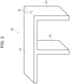
- FIG. 2 illustrates hollow member 60 expanded by air injected inside.
- hollow member 60 includes first part 62 in a long and flat rectangular parallelepiped shape disposed at an upper end of pack case 80, and a plurality of second parts 63, 64 each of which is in a rectangular parallelepiped shape extending in a downward direction orthogonal to corresponding one of a plurality of positions in the longitudinal direction of first part 62 while being inflated by air injecting inside.
- Each of the plurality of second parts 63, 64 is disposed between the plurality of corresponding battery blocks 12 or between the exhaust valve side end of one battery block 12 and side plate part 82 at an end of pack case 80 in the longitudinal direction, the end being close to exhaust port 81.
- potting material 70 is injected into the inside of pack case 80 and the outside of hollow member 60, and is more specifically filled and cured.
- potting material 70 include a resin material such as a urethane resin, a silicone resin, or an epoxy resin. Potting material 70 is injected into pack case 80 and then cured in a thermostatic bath or the like. At this time, the potting material comes into contact with a surface of the exhaust valve side end of battery 20 exposed from first holder 41. Potting material 70 may contain a heat absorbing material such as aluminum hydroxide.
- hollow member 60 is disposed inside pack case 80 while having an outer surface facing the exhaust valve side end of battery 20 with potting material 70 filled therebetween.
- the outer surface of hollow member 60 includes a part facing at least exhaust valve side ends of the plurality of batteries 20, the part adhering to potting material 70.
- Fig. 1B illustrates hollow member 60 with a thickness exaggerated to facilitate understanding of a position of hollow member 60.
- Hollow member 60 adheres to potting material 70, and thus facilitating tearing of hollow member 60 together with potting 70 at the time of valve opening. Even after a part of hollow member 60 is torn, a duct space in an untorn part of hollow member 60 can be easily maintained.
- opening 61 of hollow member 60 is connected to exhaust port 81 of pack case 80.
- This configuration allows first part 62 and the plurality of second parts 63, 64 of hollow member 60 to form the duct space for exhausting high temperature gas exhausted from battery 20 when battery 20 is in an abnormal state.
- pack case 80 is formed including body case 83 ( Fig. 3 ) and a lid part detachably attached to one longitudinal end of body case 83.
- body case 83 Fig. 3
- lid part detachably attached to one longitudinal end of body case 83.
- the plurality of battery blocks 12 and hollow member 60 with its inside expanded are disposed inside pack case 80 with body case 83 disposed with a longitudinal direction aligned with a vertical direction and with the one longitudinal end facing upward.
- hollow member 60 is provided with no opening and is in a sealed state.
- the lid part is attached to body case 83 to close an opening of body case 83.
- opening 61 is formed in hollow member 60 with potting material 70 cured using a needle-shaped tool or the like through exhaust port 81 formed in the lid part, thereby forming battery pack 10. Opening 61 may be formed in hollow member 60 before the lid part is attached to body case 83. Even when opening 61 is formed in hollow member 60 to fail to maintain a shape of a sealed state, a space allowing gas to flow can be formed inside hollow member 60 if potting curing is completed. Hollow member 60 may be inflated after being inserted into body case 83, or may be inflated before being inserted.
- Hollow member 60 is expanded into a shape that is not limited to the shape illustrated in Fig. 2 , and can be changed in shape according to the number and placement positions of battery blocks 12 disposed in pack case 80, for example.
- Two battery blocks 12 facing each other may be disposed with respective exhaust valve side ends facing each other.
- the plurality of second parts of the hollow member includes a second part that is disposed between side plate part 82 of pack case 80 and an end of battery block 12 on a side opposite to the exhaust valve, and that may be eliminated.
- Fig. 4 is a schematic sectional view illustrating a state in which an abnormality has occurred in some batteries 20 constituting battery pack 10 and high temperature gas is exhausted to the outside from battery 20 in which the abnormality has occurred.
- exhaust valve 34 Fig. 1B
- hollow member 60 faces the exhaust valve end of battery 20 with potting material 70 filled therebetween, so that high temperature gas of the abnormal battery breaks through potting material 70 and hollow member 60 to enter the inside of hollow member 60.
- Fig. 4 illustrates a diagram in which an openable lid of hollow member 60 is opened to allow high temperature gas to enter the inside, the gas actually enters the inside while breaking through hollow member 60.
- the outer surface of hollow member 60 may face the outside of one axial end serving as the exhaust valve side end of battery 20 without the potting material filled.
- Battery pack 10 includes hollow member 60 provided with a hole that is not provided on a surface facing battery block 12, or with only opening 61 connected to exhaust port 81 of pack case 80, and thus enables potting material 70 to be prevented from entering the inside of hollow member 60 through the hole during assembly of battery pack 10.
- This configuration enables preventing an internal space of hollow member 60 as a gas discharge path inside battery pack 10 from being filled with potting material 70, and thus enables satisfactorily exhausting high temperature gas from battery 20 to the outside of pack case 80 when battery 20 is in an abnormal state.
- battery pack 10 can be improved in reliability.
- potting material 70 is provided around battery 20, so that the chain reaction of thermal runaway of battery 20 can be prevented by holding battery 20 and absorbing or alleviating heat generated by battery 20 using potting material 70. This configuration also allows battery pack 10 to be improved in reliability.
- the configuration of the present example also enables reducing a sealing part with an adhesive for preventing potting material 70 from leaking out to a part other than a periphery of battery 20 inside pack case 80 even though potting material 70 is provided around battery 20.
- a sealing part with an adhesive for preventing leakage of potting material 70 from between first holder 41 and second holder 42 or between each of holders 41, 42 and battery 20 can be eliminated.
- the potting material is not necessarily cured and molded by battery block 12 alone in holder 40, so that structure of holder 40 and structure of battery pack 10 can be simplified.
- Potting material 70 also has a waterproof function, so that a waterproof bag for preventing water from entering battery 20 is not required to be provided inside pack case 80.
- This configuration also enables battery pack 10 to be simplified in structure. Potting material 70 is also filled between the exhaust valve side end of each battery 20 and hollow member 60, so that the exhaust valve side end of battery 20 is not necessarily covered with a protective plate for preventing the chain reaction of thermal runaway of battery 20. This configuration enables reducing the number of parts of battery pack 10, and thus enables structure to be simplified while ensuring reliability.
- Hollow member 60 is in the shape of a flexible bag formed of a sheet material made of a resin, and includes at least a part of the outer surface, the part facing the exhaust valve side end parts of the plurality of batteries 20 and adhering to potting material 70.
- This configuration enables high temperature gas from an abnormal battery to easily break through hollow member 60, and thus enables the high temperature gas to flow into hollow member 60.
- Fig. 5 is a diagram corresponding to an enlarged view of part B of Fig. 4 showing a state in which high temperature gas is exhausted trough openings of hollow member 60 in another example of a battery pack.
- a plurality of small holes 84 each having a diameter of less than or equal to 1 mm, for example, may be formed as exhaust ports in pack case 80a. Then, one or more openings 61a are formed in hollow member 60 to be connected to the plurality of corresponding small holes 84.
- openings 61a may be formed in hollow member 60 using a tool or the like after the inside of hollow member 60 is inflated with air and sealed, and hollow member 60 is disposed inside pack case 80 and potting material 70 injected to the outside of hollow member 60 is cured.
- gas exhausted from an abnormal battery is exhausted to the outside through opening 61a and the plurality of small holes 84 as indicated by arrows ⁇ in Fig. 5 .
- Fig. 6 is a schematic sectional view illustrating a state in which an abnormality has occurred in some batteries 20 in battery pack 10a of a comparative example and high temperature gas is exhausted to the outside from battery 20 in which the abnormality has occurred.
- Battery pack 10a of the comparative example includes pack case 80 that is provided inside with no hollow member 60.
- Each battery block 12 includes potting material 70 provided around battery 20, first holder 41 and second holder 51 including respective outer peripheral side end parts approaching each other to form a gap, and sealing part 85 made of an adhesive for preventing leakage of potting material 70, sealing part 85 being provided in the gap.
- the sealing part made of the adhesive is also provided between each of holders 41, 51 and battery 20.
- Each battery block 12 further includes protective plate 87 for preventing a chain reaction of thermal runaway of batteries 20, protective plate 87 being provided in a part covering holder opening 44 of first holder 41 at an exhaust valve side end of each battery 20.
- protective plate 87 is broken by high pressure gas exhausted from any battery 20, and the gas is exhausted to the outside through exhaust path 91 between battery blocks 12 and exhaust port 81 as illustrated in Fig. 6 .
- pack case 80 is provided inside with waterproof pack 90 that is sealed while accommodating the plurality of battery blocks 12. Waterproof pack 90 prevents water from entering each battery 20 from the outside.
- hollow member 60 in a sealed state may be connected on its outer surface to exhaust port 81 of pack case 80 directly or with potting material 70 filled therebetween.
- exhaust port 81 of pack case 80 is enlarged to some extent in this case, a part of hollow member 60, the part facing exhaust port 81, may be cleaved by force of gas exhausted from some batteries 20 to exhaust the gas to the outside. Sealing hollow member 60 in this case enables preventing potting material 70 from entering the inside of hollow member 60 through a hole during assembly of battery pack 10.
- battery pack 10 is described in the exemplary embodiment described above in which battery holder 40 is provided to hold battery 20, battery holder 40 may be eliminated.
- a holding part for holding battery 20 may be directly formed on an inner surface of a pack case.
- Structure of the exhaust valve of battery 20 is not limited to the configuration illustrated in Fig. 1B .
- the sealing body attached to the case body of battery 20 may be provided inside with a valve body structure that is broken when internal pressure increases, and provided with an outer end that does not break.
- hollow member 60 disposed inside pack case 80 is described in the exemplary embodiment described above in which hollow member 60 is in the shape of a bag, hollow member 60 is not limited thereto.
- the hollow member may be made of resin and have rigidity.
- the hollow member in this case includes a part facing the exhaust valve side end of the battery with the potting material filled therebetween, and the part may be provided with an annular or C-shaped thin wall part to be easily broken by pressure of applied gas.
Landscapes
- Chemical & Material Sciences (AREA)
- Chemical Kinetics & Catalysis (AREA)
- Electrochemistry (AREA)
- General Chemical & Material Sciences (AREA)
- Engineering & Computer Science (AREA)
- Power Engineering (AREA)
- Microelectronics & Electronic Packaging (AREA)
- Battery Mounting, Suspending (AREA)
- Gas Exhaust Devices For Batteries (AREA)
Abstract
Description
- The present disclosure relates to a power storage pack.
- In general, a power storage device such as a cylindrical lithium-ion battery is used in the form of a power storage pack in which a plurality of power storage devices is electrically connected to each other and housed in a case. At this time, when a power storage device in the power storage pack has an abnormality, the power storage device generates high temperature gas. This high temperature gas remaining in the power storage pack may adversely affect a power storage device in a normal state. Thus, the power storage pack is provided inside with an exhaust path to exhaust the high temperature gas to the outside of the case through the exhaust path.
- PTL 1 discloses a power storage device (power storage pack) as an example of a power storage pack, in which a plurality of batteries each including an exterior container in the shape of a rectangular box is housed in a storage container body (pack case). Each battery has a side wall provided with a safety valve (exhaust valve) that is broken when internal pressure increases. The storage container body is provided inside with a collection space partitioned by a partition wall from a battery placement space, and the safety valve of the battery faces a collection port formed in the partition wall. This configuration intends to collect electrolytic solution ejected from the battery and flame of the electrolytic solution into the collection space through the collection port due to breakage of the safety valve of the battery.
- PTL 1: Unexamined
Japanese Patent Publication No. 2014-160573 - The configuration disclosed in PTL 1 includes the collection space that corresponds to an exhaust path of gas ejected from the battery. Alternatively, to improve safety at the time of thermal runaway of a battery, it is conceivable to dispose and cure a potting material (resin filler) around the battery to absorb or alleviate heat of the battery with an abnormality having occurred with the potting material. Unfortunately, when the configuration in which the potting material is injected around the battery is used in the configuration disclosed in PTL 1, the potting material before curing may enter the gas exhaust path through the collection port during assembly of the power storage pack to fill the gas exhaust path with the potting material, and thus high temperature gas may fail to be satisfactorily exhausted from the battery when the battery is in an abnormal state. Even structure in which the high temperature gas of the battery is exhausted to the outside of the power storage pack through the gas exhaust path of the pack case of the power storage pack may cause an inconvenience in PTL 1 as in when the potting material is used. Thus, this structure has room for improvement in terms of improvement in reliability of the power storage pack. This structure further has room for improvement in terms of simplification of structure.
- It is an object of the present disclosure to provide a power storage pack simplified in structure and improved in reliability in a configuration in which a resin filler is disposed around a power storage device.
- A power storage pack of the present disclosure includes: at least one power storage block including at least one power storage device including an exhaust valve; a pack case accommodating the at least one power storage block and including an exhaust port; a hollow member interposed between the pack case and the at least one power storage block, a part of the hollow member facing the exhaust valve of the at least one power storage device; and a resin filler interposed between the at least one power storage device and the hollow member, the hollow member including an opening and an outer surface any of which is connected to the exhaust port of the pack case.
- The power storage pack of the present disclosure enables the configuration, in which the resin filler is disposed around the power storage device, to be simplified in structure and improved in reliability.
-
-
Fig. 1A is a schematic sectional view of a battery pack according to an exemplary embodiment. -
Fig. 1B is an enlarged view corresponding to part A of the battery pack ofFig. 1 . -
Fig. 2 is a perspective view illustrating a hollow member taken out from the battery pack ofFig. 1 . -
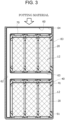
Fig. 3 is a schematic sectional view illustrating an example of a method for injecting a potting material into a battery pack. -
Fig. 4 is a schematic sectional view illustrating a state in which an abnormality has occurred in some batteries constituting the battery pack ofFig. 1 and high temperature gas is exhausted to the outside from the battery in which the abnormality has occurred. -
Fig. 5 is a diagram corresponding to an enlarged view of part B ofFig. 4 showing a state in which high temperature gas is exhausted trough openings of a hollow member in another example of a battery pack. -
Fig. 6 is a schematic sectional view illustrating a state in which an abnormality has occurred in some batteries in a battery pack of a comparative example and high temperature gas is exhausted to the outside from a battery in which the abnormality has occurred. - Hereinafter, an exemplary embodiment of the present disclosure will be described with reference to the drawings. Shapes, materials, directions, and numbers to be described below are examples, and can be appropriately changed according to specifications of a power storage pack. Hereinafter, the power storage pack will be exemplified using a battery pack using a lithium-ion secondary battery as a power storage device. However, the power storage pack of the present disclosure is not limited thereto.
The power storage device may be another secondary battery such as a nickel hydrogen battery or a capacitor such as an electric double layer capacitor. -
Fig. 1A shows a schematic configuration ofbattery pack 10.Battery pack 10 is used as a power source for a device driven by an electric motor, such as for an electric car, an electric assist bicycle, or an electric motorcycle.Battery pack 10 is not limited to application above, and can be used as a power source for various electric devices. -
Battery pack 10 includesbattery block 12 corresponding to a plurality of power storage blocks housing a plurality of batteries, andpack case 80 housing a plurality ofbattery blocks 12. As each battery, a non-aqueous electrolyte secondary battery such as a lithium-ion battery is used, for example. The battery is not particularly limited in shape, size, and the like, and preferably has a cylindrical shape. Hereinafter, the battery being a cylindrical battery will be mainly described.Battery block 12 includes a plurality ofbatteries 20 andholder 40, and the plurality ofbatteries 20 each include opposite ends in a predetermined direction, specifically in a length direction, the opposite ends are each accommodated in corresponding one offirst holder 41 andsecond holder 51constituting holder 40.Fig 1A illustratesbattery 20 with a slanted lattice. When the battery is a rectangular battery, opposite ends of the battery in a height direction as a predetermined direction may be accommodated in a battery holder. -
Pack case 80 has the shape of a substantially rectangular parallelepiped box made of resin or metal.Pack case 80 is provided inside with a plurality ofbattery blocks 12 disposed separately in the length direction (the left-right direction inFig. 1A ).Pack case 80 is provided inside with an upper end part in which an upper part ofhollow member 60 described later is disposed.Hollow member 60 includes opening 61 that communicates with the outside throughexhaust port 81 provided inpack case 80.Exhaust port 81 is a small hole having a diameter of about several mm, for example.Hollow member 60 exhausts gas exhausted from at least a part of the plurality ofbatteries 20 to the outside throughexhaust port 81. Hereinafter,battery 20 is referred to asbattery 20. -
Battery 20 will be described with reference toFig. 1B .Battery 20 is a lithium-ion secondary battery or the like, and includeselectrode group 22, a non-aqueous electrolyte (not illustrated), andbattery case 30 that accommodateselectrode group 22 and the non-aqueous electrolyte.Battery case 30 is made of metal, and includescase body 31 having a substantially cylindrical shape with a bottom, and sealingbody 32 that closes an upper end opening ofcase body 31 in an insulated state. -
Electrode group 22 is a winding-type electrode group in whichpositive electrode 23 in the shape of a strip and negative electrode 24 in the shape of a strip are wound with separator 25 in the shape of a strip interposed therebetween.Electrode group 22 includes upper and lower ends on each of whichinsulating plate 26 is disposed.Positive electrode 23 is connected topositive electrode tab 27 that extends upward to be connected to a bottom surface of sealingbody 32. Negative electrode 24 includes an outermost peripheral surface that comes into contact with an inner peripheral surface ofbattery case 30 to electrically connect negative electrode 24 tocase body 31. Negative electrode 24 includes a negative electrode tab that extends downward, and the negative electrode tab may be connected to a bottom plate part ofcase body 31. -
Case body 31 is provided in an outer peripheral surface of its upper end part withgroove part 31a in an annular shape formed by press molding or the like from the outside, and is provided on the upper end part withoverhang part 31b overhanging inward in a radial direction along with formation ofgroove part 31a.Overhang part 31b supports sealingbody 32 withgasket 35 interposed therebetween on its upper surface.Case body 31 includes upper end opening edge part G that is caulked to be bent inward ofbattery case 30 withgasket 35 disposed on an inner peripheral side, and an opening ofcase body 31 is sealed by sealingbody 32 being vertically sandwiched between upper end opening edge part G andoverhang part 31b withgasket 35 interposed therebetween. - Sealing
body 32 is made of metal and has a substantially disk shape. Sealingbody 32 is provided withexhaust valve 34 in a substantially circular shape with an outer peripheral edge defined bythin wall part 33 in an annular shape.Exhaust valve 34 bursts outward when the inside ofbattery case 30 reaches a predetermined pressure or more to break or meltthin wall part 33, and thus exhausting gas inside. That is, each of the plurality ofbatteries 20 is provided at one axial end withexhaust valve 34 that opens due to an increase in internal pressure. At this time, an outer surface (lower surface inFig. 1B ) ofhollow member 60 faces the outside of one axial end (upper end inFig. 1B ) serving as an exhaust valve side end ofbattery 20 withpotting material 70 injected intopack case 80.Figs. 1A and1B each illustrate pottingmaterial 70 with a sandy part. -
Hollow member 60 is provided with only a hole serving as opening 61 connected to exhaustport 81 described later ofpack case 80. This configuration enables pottingmaterial 70 to be prevented from entering the inside ofhollow member 60 during assembly ofbattery pack 10 as described later, so that high temperature gas can be satisfactorily exhausted frombattery 20 to the outside ofpack case 80 whenbattery 20 is in an abnormal state. Then, pottingmaterial 70 is provided aroundbattery 20, so that a chain reaction of thermal runaway ofbattery 20 can be prevented by absorbing or alleviating heat generated bybattery 20 usingpotting material 70. The power storage pack of the present disclosure does not necessarily require heat absorption using the potting material. -
First holder 41 andsecond holder 51 ofholder 40 are each made of a curable resin, for example. The curable resin constituting each ofholders holders holders -
First holder 41 includes a plurality offirst containers 43 each of which is provided withholder opening 44 axially facingexhaust valve 34 of corresponding one ofbatteries 20. Holder opening 44 is in a circular shape, for example. -
First holder 41 is also provided on its side surface with positiveelectrode terminal plate 65 is provided, and a plurality of positiveelectrode lead parts 66 extending from positiveelectrode terminal plate 65 is electrically connected to sealingbody 32 serving as a positive electrode terminal at one end part ofbattery 20 throughholder opening 44. - Each of a plurality of
batteries 20 as described above includes opposite end parts in a longitudinal direction that are accommodated and held byfirst holder 41 andsecond holder 51, thereby formingbattery block 12. Each ofholders batteries 20. Each ofholders containers 43 andholder openings 44 provided at respective bottoms ofcontainers 43 according to the number and placement positions ofbatteries 20 constitutingbattery block 12. For example, the plurality ofbatteries 20 is provided side by side in a width direction (front-back direction of the sheet ofFig. 1A ) orthogonal to the longitudinal direction ofpack case 80, or provided in a staggered placement, in eachbattery block 12, andholder openings 44 are formed according to corresponding positions of the plurality ofbatteries 20. Each ofholders batteries 20 through corresponding one ofholder openings 44. -
Fig. 1A illustrates twobattery blocks 12 disposed separately in the longitudinal direction ofpack case 80. Two battery blocks 12 include respective exhaust valve side ends disposed on the same side (right side inFig. 1A ) in the longitudinal direction ofpack case 80. The number of battery blocks 12 disposed insidepack case 80 is not limited to two, and may be only one, or three or more. When a current collector electrically connecting the plurality ofbatteries 20 is used in eachbattery block 12, battery blocks 12 may be connected to each other by extending a part of the current collector, or by passing overhollow member 60 using another conductive member. -
Pack case 80 is further provided inside withhollow member 60. As illustrated inFig. 2 ,hollow member 60 is in the shape of a flexible bag formed of a sheet material made of a resin such as polyvinyl chloride, polyethylene, or polypropylene and having a small thickness (e.g., less than or equal to 0.1 mm, preferably less than or equal to 0.02 mm).Hollow member 60 may be transparent or translucent. As described later, afterhollow member 60 is disposed insidepack case 80 andpotting material 70 injected outsidehollow member 60 is cured, opening 61 connected to exhaustport 81 ofpack case 80 is formed at an upper part of one end part (right end part inFig. 2 ) in a longitudinal direction ofhollow member 60.Hollow member 60 is preferably configured such that no hole is normally formed other than opening 61 connected to exhaustport 81 or no hole is formed on a surface facing the battery block. The shape of the hollow member of the present disclosure is not limited to the shape of a bag. The hollow member may have the shape of a hollow box. -
Fig. 2 illustrateshollow member 60 expanded by air injected inside. As illustrated inFig. 2 ,hollow member 60 includesfirst part 62 in a long and flat rectangular parallelepiped shape disposed at an upper end ofpack case 80, and a plurality ofsecond parts first part 62 while being inflated by air injecting inside. Each of the plurality ofsecond parts battery block 12 andside plate part 82 at an end ofpack case 80 in the longitudinal direction, the end being close toexhaust port 81. - Then, potting
material 70 is injected into the inside ofpack case 80 and the outside ofhollow member 60, and is more specifically filled and cured. Examples of pottingmaterial 70 include a resin material such as a urethane resin, a silicone resin, or an epoxy resin.Potting material 70 is injected intopack case 80 and then cured in a thermostatic bath or the like. At this time, the potting material comes into contact with a surface of the exhaust valve side end ofbattery 20 exposed fromfirst holder 41.Potting material 70 may contain a heat absorbing material such as aluminum hydroxide. - As illustrated in
Fig. 1B ,hollow member 60 is disposed insidepack case 80 while having an outer surface facing the exhaust valve side end ofbattery 20 withpotting material 70 filled therebetween. At this time, the outer surface ofhollow member 60 includes a part facing at least exhaust valve side ends of the plurality ofbatteries 20, the part adhering to pottingmaterial 70.Fig. 1B illustrateshollow member 60 with a thickness exaggerated to facilitate understanding of a position ofhollow member 60.Hollow member 60 adheres to pottingmaterial 70, and thus facilitating tearing ofhollow member 60 together with potting 70 at the time of valve opening. Even after a part ofhollow member 60 is torn, a duct space in an untorn part ofhollow member 60 can be easily maintained. - As illustrated in
Fig. 1A , opening 61 ofhollow member 60 is connected to exhaustport 81 ofpack case 80. This configuration allowsfirst part 62 and the plurality ofsecond parts hollow member 60 to form the duct space for exhausting high temperature gas exhausted frombattery 20 whenbattery 20 is in an abnormal state. - Work of injecting
potting material 70 intopack case 80 is performed as follows, for example. First,pack case 80 is formed including body case 83 (Fig. 3 ) and a lid part detachably attached to one longitudinal end ofbody case 83. As illustrated inFig. 3 , the plurality of battery blocks 12 andhollow member 60 with its inside expanded are disposed insidepack case 80 withbody case 83 disposed with a longitudinal direction aligned with a vertical direction and with the one longitudinal end facing upward. At this time,hollow member 60 is provided with no opening and is in a sealed state. Then, after pottingmaterial 70 is injected from abovebody case 83, the lid part is attached tobody case 83 to close an opening ofbody case 83. After that, opening 61 is formed inhollow member 60 withpotting material 70 cured using a needle-shaped tool or the like throughexhaust port 81 formed in the lid part, thereby formingbattery pack 10.Opening 61 may be formed inhollow member 60 before the lid part is attached tobody case 83. Even when opening 61 is formed inhollow member 60 to fail to maintain a shape of a sealed state, a space allowing gas to flow can be formed insidehollow member 60 if potting curing is completed.Hollow member 60 may be inflated after being inserted intobody case 83, or may be inflated before being inserted. -
Hollow member 60 is expanded into a shape that is not limited to the shape illustrated inFig. 2 , and can be changed in shape according to the number and placement positions of battery blocks 12 disposed inpack case 80, for example. Two battery blocks 12 facing each other may be disposed with respective exhaust valve side ends facing each other. At this time, the plurality of second parts of the hollow member includes a second part that is disposed betweenside plate part 82 ofpack case 80 and an end ofbattery block 12 on a side opposite to the exhaust valve, and that may be eliminated. -
Fig. 4 is a schematic sectional view illustrating a state in which an abnormality has occurred in somebatteries 20 constitutingbattery pack 10 and high temperature gas is exhausted to the outside frombattery 20 in which the abnormality has occurred. When an abnormality occurs in somebatteries 20 to increase battery internal pressure abnormally, exhaust valve 34 (Fig. 1B ) of the abnormal battery is broken and burst out outward. At this time,hollow member 60 faces the exhaust valve end ofbattery 20 withpotting material 70 filled therebetween, so that high temperature gas of the abnormal battery breaks throughpotting material 70 andhollow member 60 to enter the inside ofhollow member 60. Then, the gas ejected from the abnormal battery passes through the inside ofhollow member 60 and is exhausted to the outside through opening 61 ofhollow member 60 andexhaust port 81 ofpack case 80 as indicated by arrow α inFig. 4 . AlthoughFig. 4 illustrates a diagram in which an openable lid ofhollow member 60 is opened to allow high temperature gas to enter the inside, the gas actually enters the inside while breaking throughhollow member 60. Unlike the above configuration, the outer surface ofhollow member 60 may face the outside of one axial end serving as the exhaust valve side end ofbattery 20 without the potting material filled. -
Battery pack 10 includeshollow member 60 provided with a hole that is not provided on a surface facingbattery block 12, or with only opening 61 connected to exhaustport 81 ofpack case 80, and thus enables pottingmaterial 70 to be prevented from entering the inside ofhollow member 60 through the hole during assembly ofbattery pack 10. This configuration enables preventing an internal space ofhollow member 60 as a gas discharge path insidebattery pack 10 from being filled withpotting material 70, and thus enables satisfactorily exhausting high temperature gas frombattery 20 to the outside ofpack case 80 whenbattery 20 is in an abnormal state. As a result,battery pack 10 can be improved in reliability. Then, pottingmaterial 70 is provided aroundbattery 20, so that the chain reaction of thermal runaway ofbattery 20 can be prevented by holdingbattery 20 and absorbing or alleviating heat generated bybattery 20 usingpotting material 70. This configuration also allowsbattery pack 10 to be improved in reliability. - The configuration of the present example also enables reducing a sealing part with an adhesive for preventing
potting material 70 from leaking out to a part other than a periphery ofbattery 20 insidepack case 80 even though pottingmaterial 70 is provided aroundbattery 20. For example, a sealing part with an adhesive for preventing leakage of pottingmaterial 70 from betweenfirst holder 41 and second holder 42 or between each ofholders 41, 42 andbattery 20 can be eliminated. As described above, the potting material is not necessarily cured and molded bybattery block 12 alone inholder 40, so that structure ofholder 40 and structure ofbattery pack 10 can be simplified.Potting material 70 also has a waterproof function, so that a waterproof bag for preventing water from enteringbattery 20 is not required to be provided insidepack case 80. This configuration also enablesbattery pack 10 to be simplified in structure.Potting material 70 is also filled between the exhaust valve side end of eachbattery 20 andhollow member 60, so that the exhaust valve side end ofbattery 20 is not necessarily covered with a protective plate for preventing the chain reaction of thermal runaway ofbattery 20. This configuration enables reducing the number of parts ofbattery pack 10, and thus enables structure to be simplified while ensuring reliability. -
Hollow member 60 according to the exemplary embodiment is in the shape of a flexible bag formed of a sheet material made of a resin, and includes at least a part of the outer surface, the part facing the exhaust valve side end parts of the plurality ofbatteries 20 and adhering to pottingmaterial 70. This configuration enables high temperature gas from an abnormal battery to easily break throughhollow member 60, and thus enables the high temperature gas to flow intohollow member 60. -
Fig. 5 is a diagram corresponding to an enlarged view of part B ofFig. 4 showing a state in which high temperature gas is exhausted trough openings ofhollow member 60 in another example of a battery pack. As in another example illustrated inFig. 5 , a plurality ofsmall holes 84 each having a diameter of less than or equal to 1 mm, for example, may be formed as exhaust ports inpack case 80a. Then, one ormore openings 61a are formed inhollow member 60 to be connected to the plurality of correspondingsmall holes 84. For example,openings 61a may be formed inhollow member 60 using a tool or the like after the inside ofhollow member 60 is inflated with air and sealed, andhollow member 60 is disposed insidepack case 80 andpotting material 70 injected to the outside ofhollow member 60 is cured. When an abnormality occurs in somebatteries 20, gas exhausted from an abnormal battery is exhausted to the outside throughopening 61a and the plurality ofsmall holes 84 as indicated by arrows β inFig. 5 . -
Fig. 6 is a schematic sectional view illustrating a state in which an abnormality has occurred in somebatteries 20 inbattery pack 10a of a comparative example and high temperature gas is exhausted to the outside frombattery 20 in which the abnormality has occurred.Battery pack 10a of the comparative example includespack case 80 that is provided inside with nohollow member 60. Eachbattery block 12 includespotting material 70 provided aroundbattery 20,first holder 41 andsecond holder 51 including respective outer peripheral side end parts approaching each other to form a gap, and sealingpart 85 made of an adhesive for preventing leakage of pottingmaterial 70, sealingpart 85 being provided in the gap. The sealing part made of the adhesive is also provided between each ofholders battery 20. - Each
battery block 12 further includesprotective plate 87 for preventing a chain reaction of thermal runaway ofbatteries 20,protective plate 87 being provided in a partcovering holder opening 44 offirst holder 41 at an exhaust valve side end of eachbattery 20. When an abnormality occurs in somebatteries 20,protective plate 87 is broken by high pressure gas exhausted from anybattery 20, and the gas is exhausted to the outside throughexhaust path 91 between battery blocks 12 andexhaust port 81 as illustrated inFig. 6 . Additionally,pack case 80 is provided inside withwaterproof pack 90 that is sealed while accommodating the plurality of battery blocks 12.Waterproof pack 90 prevents water from entering eachbattery 20 from the outside. - Although such a comparative example requires sealing
part 85,protective plate 87, andwaterproof pack 90 to be provided for preventing leakage of pottingmaterial 70 to result in complicated structure, the exemplary embodiment described above enables reduction in each of sealingpart 85,protective plate 87, andwaterproof pack 90. - As another example of the exemplary embodiment of
battery pack 10,hollow member 60 in a sealed state may be connected on its outer surface to exhaustport 81 ofpack case 80 directly or withpotting material 70 filled therebetween. Whenexhaust port 81 ofpack case 80 is enlarged to some extent in this case, a part ofhollow member 60, the part facingexhaust port 81, may be cleaved by force of gas exhausted from somebatteries 20 to exhaust the gas to the outside. Sealinghollow member 60 in this case enables preventingpotting material 70 from entering the inside ofhollow member 60 through a hole during assembly ofbattery pack 10. - Although
battery pack 10 is described in the exemplary embodiment described above in whichbattery holder 40 is provided to holdbattery 20,battery holder 40 may be eliminated. For example, a holding part for holdingbattery 20 may be directly formed on an inner surface of a pack case. - Structure of the exhaust valve of
battery 20 is not limited to the configuration illustrated inFig. 1B . For example, the sealing body attached to the case body ofbattery 20 may be provided inside with a valve body structure that is broken when internal pressure increases, and provided with an outer end that does not break. - Although
hollow member 60 disposed insidepack case 80 is described in the exemplary embodiment described above in which hollowmember 60 is in the shape of a bag,hollow member 60 is not limited thereto. For example, the hollow member may be made of resin and have rigidity. The hollow member in this case includes a part facing the exhaust valve side end of the battery with the potting material filled therebetween, and the part may be provided with an annular or C-shaped thin wall part to be easily broken by pressure of applied gas. -
- 10, 10a: battery pack (power storage pack)
- 12: battery block (power storage block)
- 20: battery (power storage device)
- 22: electrode group
- 23: positive electrode
- 24: negative electrode
- 25: separator
- 26: insulating plate
- 27: positive electrode tab
- 30: battery case
- 31: case body
- 32: sealing body
- 33: thin wall part
- 34: battery exhaust valve
- 35: gasket
- 40: battery holder
- 41: first holder
- 43: first container
- 44: holder opening
- 51: second holder
- 60: hollow member
- 61, 61a: opening
- 62: first part
- 63, 64: second part
- 65: positive electrode terminal plate
- 66: positive electrode lead part
- 70: potting material (resin filler)
- 80: pack case
- 81: exhaust port
- 82: side plate part
- 83: body case
- 84: small hole
- 85: sealing part
- 87: protective plate
- 90: waterproof pack
- 91: exhaust path
Claims (4)
- A power storage pack comprising:at least one power storage block including at least one power storage device including an exhaust valve;a pack case accommodating the at least one power storage block and including an exhaust port;a hollow member interposed between the pack case and the at least one power storage block, a part of the hollow member facing the exhaust valve of the at least one power storage device; anda resin filler interposed between the at least one power storage device and the hollow member,the hollow member including an opening and an outer surface any of which is connected to the exhaust port of the pack case.
- The power storage pack according to Claim 1, wherein the resin filler is interposed between the exhaust valve of the at least one power storage device and the hollow member.
- The power storage pack according to Claim 1, wherein the hollow member is in a shape of a flexible bag formed of a sheet material made of a resin, and the outer surface of the hollow member includes a part facing an end, closer to the exhaust valve, of the at least one power storage device, the part adhering to the resin filler.
- The power storage pack according to any one of Claims 1 to 3, whereinthe at least one power storage device comprises a plurality of power storage devices,the plurality of power storage devices includes a holder that restricts a distance between the power storage devices,the holder exposes a part of the plurality of power storage devices, and
the resin filler is in contact with a surface of the part of the power storage devices, the surface being exposed from the holder.
Applications Claiming Priority (2)
| Application Number | Priority Date | Filing Date | Title |
|---|---|---|---|
| JP2022013540 | 2022-01-31 | ||
| PCT/JP2023/002463 WO2023145829A1 (en) | 2022-01-31 | 2023-01-26 | Electricity storage pack |
Publications (2)
| Publication Number | Publication Date |
|---|---|
| EP4475313A1 true EP4475313A1 (en) | 2024-12-11 |
| EP4475313A4 EP4475313A4 (en) | 2025-04-30 |
Family
ID=87471521
Family Applications (1)
| Application Number | Title | Priority Date | Filing Date |
|---|---|---|---|
| EP23747039.8A Pending EP4475313A4 (en) | 2022-01-31 | 2023-01-26 | POWER STORAGE PACK |
Country Status (5)
| Country | Link |
|---|---|
| US (1) | US20250132451A1 (en) |
| EP (1) | EP4475313A4 (en) |
| JP (1) | JPWO2023145829A1 (en) |
| CN (1) | CN118613956A (en) |
| WO (1) | WO2023145829A1 (en) |
Families Citing this family (3)
| Publication number | Priority date | Publication date | Assignee | Title |
|---|---|---|---|---|
| CN120184497A (en) * | 2023-12-20 | 2025-06-20 | 蔚来电池科技(安徽)有限公司 | Battery pack and electricity utilization device |
| WO2025008003A1 (en) * | 2024-02-05 | 2025-01-09 | 惠州亿纬锂能股份有限公司 | Battery pack |
| CN121238121A (en) * | 2024-06-28 | 2025-12-30 | 小米汽车科技有限公司 | Battery packs and their potting methods, and vehicles |
Family Cites Families (8)
| Publication number | Priority date | Publication date | Assignee | Title |
|---|---|---|---|---|
| JP2007027011A (en) * | 2005-07-20 | 2007-02-01 | Sanyo Electric Co Ltd | Power supply |
| US9231237B2 (en) * | 2010-08-06 | 2016-01-05 | Panasonic Intellectual Property Management Co., Ltd. | Cell module |
| JP6279834B2 (en) | 2013-02-20 | 2018-02-14 | ホーチキ株式会社 | Power storage device and moving body or facility using the same |
| JP2015018706A (en) * | 2013-07-11 | 2015-01-29 | 株式会社豊田自動織機 | Power storage device module |
| KR102258286B1 (en) * | 2014-10-21 | 2021-05-31 | 에스케이이노베이션 주식회사 | Battery cell, and battery module |
| US10644286B2 (en) * | 2016-04-22 | 2020-05-05 | Farasis Energy (Ganzhou) Co., Ltd. | Secondary battery with venting mechanism |
| DE102018122080A1 (en) * | 2018-09-11 | 2020-03-12 | Webasto SE | Battery module and method for manufacturing a battery module |
| CN210182427U (en) * | 2019-04-16 | 2020-03-24 | 上海申传电气股份有限公司 | Cast-in explosion-proof structure of lithium battery power supply |
-
2023
- 2023-01-26 EP EP23747039.8A patent/EP4475313A4/en active Pending
- 2023-01-26 WO PCT/JP2023/002463 patent/WO2023145829A1/en not_active Ceased
- 2023-01-26 CN CN202380018920.3A patent/CN118613956A/en active Pending
- 2023-01-26 US US18/730,696 patent/US20250132451A1/en active Pending
- 2023-01-26 JP JP2023576983A patent/JPWO2023145829A1/ja active Pending
Also Published As
| Publication number | Publication date |
|---|---|
| WO2023145829A1 (en) | 2023-08-03 |
| CN118613956A (en) | 2024-09-06 |
| EP4475313A4 (en) | 2025-04-30 |
| JPWO2023145829A1 (en) | 2023-08-03 |
| US20250132451A1 (en) | 2025-04-24 |
Similar Documents
| Publication | Publication Date | Title |
|---|---|---|
| EP4475313A1 (en) | Electricity storage pack | |
| EP4057434B1 (en) | Battery module, battery pack comprising same, and automobile | |
| CN213782158U (en) | Batteries, devices including batteries and apparatus for making batteries | |
| JP5583538B2 (en) | Battery pack | |
| US9159983B2 (en) | Battery, vehicle mounting the battery, and device mounting the battery | |
| CN114175377A (en) | Battery and related device, preparation method and preparation equipment thereof | |
| CN100502125C (en) | Rechargeable battery with gas release safety vent | |
| KR101310015B1 (en) | Sealed battery | |
| JP6661759B2 (en) | Rechargeable battery pack | |
| JP4811539B2 (en) | Batteries, vehicles, and equipment using batteries | |
| KR20190042215A (en) | Secondary Battery Pouch-Type Case Having Gas Discharge Port | |
| WO2021012912A1 (en) | Top cover assembly, secondary battery, and apparatus using battery | |
| CN114175376A (en) | Battery and related device, preparation method and preparation equipment thereof | |
| CN116134670B (en) | End cap assembly, battery cell, battery and electrical device | |
| KR102761907B1 (en) | Secondary Battery | |
| KR102692525B1 (en) | Pouch cell | |
| EP2846378B1 (en) | Rechargeable battery having a fuse | |
| US12456779B2 (en) | Battery module, battery pack, and vehicle | |
| CN120239924A (en) | Battery Pack | |
| KR20120069261A (en) | Secondary battery | |
| US20220367967A1 (en) | Power storage module | |
| CN116345030B (en) | Cylindrical battery and manufacturing method thereof | |
| EP4411957B1 (en) | Battery pack | |
| KR100467701B1 (en) | Pouched-type lithium secondary battery installing safety device | |
| TW202522773A (en) | Power supply |
Legal Events
| Date | Code | Title | Description |
|---|---|---|---|
| STAA | Information on the status of an ep patent application or granted ep patent |
Free format text: STATUS: THE INTERNATIONAL PUBLICATION HAS BEEN MADE |
|
| PUAI | Public reference made under article 153(3) epc to a published international application that has entered the european phase |
Free format text: ORIGINAL CODE: 0009012 |
|
| STAA | Information on the status of an ep patent application or granted ep patent |
Free format text: STATUS: REQUEST FOR EXAMINATION WAS MADE |
|
| 17P | Request for examination filed |
Effective date: 20240815 |
|
| AK | Designated contracting states |
Kind code of ref document: A1 Designated state(s): AL AT BE BG CH CY CZ DE DK EE ES FI FR GB GR HR HU IE IS IT LI LT LU LV MC ME MK MT NL NO PL PT RO RS SE SI SK SM TR |
|
| A4 | Supplementary search report drawn up and despatched |
Effective date: 20250331 |
|
| RIC1 | Information provided on ipc code assigned before grant |
Ipc: H01M 50/342 20210101ALI20250325BHEP Ipc: H01M 50/291 20210101ALI20250325BHEP Ipc: H01M 50/289 20210101ALI20250325BHEP Ipc: H01M 50/213 20210101ALI20250325BHEP Ipc: H01M 50/204 20210101ALI20250325BHEP Ipc: H01M 50/202 20210101ALI20250325BHEP Ipc: H01G 11/78 20130101ALI20250325BHEP Ipc: H01G 11/10 20130101ALI20250325BHEP Ipc: H01M 50/35 20210101AFI20250325BHEP |
|
| DAV | Request for validation of the european patent (deleted) | ||
| DAX | Request for extension of the european patent (deleted) |