EP4475306A1 - Battery container and energy storage system comprising same - Google Patents
Battery container and energy storage system comprising same Download PDFInfo
- Publication number
- EP4475306A1 EP4475306A1 EP23799728.3A EP23799728A EP4475306A1 EP 4475306 A1 EP4475306 A1 EP 4475306A1 EP 23799728 A EP23799728 A EP 23799728A EP 4475306 A1 EP4475306 A1 EP 4475306A1
- Authority
- EP
- European Patent Office
- Prior art keywords
- container body
- bracket
- container
- support
- coupling
- Prior art date
- Legal status (The legal status is an assumption and is not a legal conclusion. Google has not performed a legal analysis and makes no representation as to the accuracy of the status listed.)
- Pending
Links
Images








Classifications
-
- H—ELECTRICITY
- H01—ELECTRIC ELEMENTS
- H01M—PROCESSES OR MEANS, e.g. BATTERIES, FOR THE DIRECT CONVERSION OF CHEMICAL ENERGY INTO ELECTRICAL ENERGY
- H01M50/00—Constructional details or processes of manufacture of the non-active parts of electrochemical cells other than fuel cells, e.g. hybrid cells
- H01M50/20—Mountings; Secondary casings or frames; Racks, modules or packs; Suspension devices; Shock absorbers; Transport or carrying devices; Holders
- H01M50/204—Racks, modules or packs for multiple batteries or multiple cells
- H01M50/207—Racks, modules or packs for multiple batteries or multiple cells characterised by their shape
- H01M50/209—Racks, modules or packs for multiple batteries or multiple cells characterised by their shape adapted for prismatic or rectangular cells
-
- H—ELECTRICITY
- H01—ELECTRIC ELEMENTS
- H01M—PROCESSES OR MEANS, e.g. BATTERIES, FOR THE DIRECT CONVERSION OF CHEMICAL ENERGY INTO ELECTRICAL ENERGY
- H01M50/00—Constructional details or processes of manufacture of the non-active parts of electrochemical cells other than fuel cells, e.g. hybrid cells
- H01M50/20—Mountings; Secondary casings or frames; Racks, modules or packs; Suspension devices; Shock absorbers; Transport or carrying devices; Holders
- H01M50/233—Mountings; Secondary casings or frames; Racks, modules or packs; Suspension devices; Shock absorbers; Transport or carrying devices; Holders characterised by physical properties of casings or racks, e.g. dimensions
-
- H—ELECTRICITY
- H01—ELECTRIC ELEMENTS
- H01M—PROCESSES OR MEANS, e.g. BATTERIES, FOR THE DIRECT CONVERSION OF CHEMICAL ENERGY INTO ELECTRICAL ENERGY
- H01M50/00—Constructional details or processes of manufacture of the non-active parts of electrochemical cells other than fuel cells, e.g. hybrid cells
- H01M50/20—Mountings; Secondary casings or frames; Racks, modules or packs; Suspension devices; Shock absorbers; Transport or carrying devices; Holders
- H01M50/251—Mountings; Secondary casings or frames; Racks, modules or packs; Suspension devices; Shock absorbers; Transport or carrying devices; Holders specially adapted for stationary devices, e.g. power plant buffering or backup power supplies
-
- H—ELECTRICITY
- H01—ELECTRIC ELEMENTS
- H01M—PROCESSES OR MEANS, e.g. BATTERIES, FOR THE DIRECT CONVERSION OF CHEMICAL ENERGY INTO ELECTRICAL ENERGY
- H01M50/00—Constructional details or processes of manufacture of the non-active parts of electrochemical cells other than fuel cells, e.g. hybrid cells
- H01M50/20—Mountings; Secondary casings or frames; Racks, modules or packs; Suspension devices; Shock absorbers; Transport or carrying devices; Holders
- H01M50/258—Modular batteries; Casings provided with means for assembling
-
- H—ELECTRICITY
- H01—ELECTRIC ELEMENTS
- H01M—PROCESSES OR MEANS, e.g. BATTERIES, FOR THE DIRECT CONVERSION OF CHEMICAL ENERGY INTO ELECTRICAL ENERGY
- H01M50/00—Constructional details or processes of manufacture of the non-active parts of electrochemical cells other than fuel cells, e.g. hybrid cells
- H01M50/20—Mountings; Secondary casings or frames; Racks, modules or packs; Suspension devices; Shock absorbers; Transport or carrying devices; Holders
- H01M50/262—Mountings; Secondary casings or frames; Racks, modules or packs; Suspension devices; Shock absorbers; Transport or carrying devices; Holders with fastening means, e.g. locks
-
- H—ELECTRICITY
- H01—ELECTRIC ELEMENTS
- H01M—PROCESSES OR MEANS, e.g. BATTERIES, FOR THE DIRECT CONVERSION OF CHEMICAL ENERGY INTO ELECTRICAL ENERGY
- H01M2220/00—Batteries for particular applications
- H01M2220/10—Batteries in stationary systems, e.g. emergency power source in plant
-
- Y—GENERAL TAGGING OF NEW TECHNOLOGICAL DEVELOPMENTS; GENERAL TAGGING OF CROSS-SECTIONAL TECHNOLOGIES SPANNING OVER SEVERAL SECTIONS OF THE IPC; TECHNICAL SUBJECTS COVERED BY FORMER USPC CROSS-REFERENCE ART COLLECTIONS [XRACs] AND DIGESTS
- Y02—TECHNOLOGIES OR APPLICATIONS FOR MITIGATION OR ADAPTATION AGAINST CLIMATE CHANGE
- Y02E—REDUCTION OF GREENHOUSE GAS [GHG] EMISSIONS, RELATED TO ENERGY GENERATION, TRANSMISSION OR DISTRIBUTION
- Y02E60/00—Enabling technologies; Technologies with a potential or indirect contribution to GHG emissions mitigation
- Y02E60/10—Energy storage using batteries
Definitions
- the present disclosure relates to a battery container and an energy storage system including the same, and more specifically, to a battery container with improved energy density and an energy storage system including the same.
- the present application claims priority to Korean Patent Application No. 10-2022-0055923 filed on May 6, 2022 in the Republic of Korea, the disclosures of which are incorporated herein by reference.
- lithium secondary batteries are in the spotlight since they can be freely charged and discharged due to little memory effect compared to nickel-based secondary batteries and have very low discharge rate and high energy density.
- the lithium secondary battery mainly uses lithium-based oxide and carbon material as a positive electrode active material and a negative electrode active material, respectively.
- the lithium secondary battery includes an electrode assembly in which a positive electrode plate and a negative electrode plate coated with a positive electrode active material and a negative electrode active material are disposed with a separator interposed therebetween, and an exterior, namely a battery case, that seals and accommodates the electrode assembly along with an electrolyte solution.
- lithium secondary batteries may be classified into can-type secondary batteries in which the electrode assembly is included in a metal can and pouch-type secondary batteries in which the electrode assembly is included in a pouch of an aluminum laminate sheet, depending on the shape of the exterior.
- the secondary battery may be used alone, but in many cases, the secondary battery is generally configured to include a plurality of secondary batteries electrically connected to each other in series and/or parallel.
- a plurality of secondary batteries may be electrically connected to each other and accommodated inside one module case to form one battery module.
- the battery module may be used alone, or two or more battery modules may be electrically connected to each other in series and/or parallel to form a higher-level device such as a battery rack or a battery pack.
- an energy storage system for storing generated power is receiving more attention.
- the smart grid system is being proposed as one of ways to control power supply and demand.
- the amount of electricity used by consumers is not always constant and may fluctuate from time to time.
- a representative example is that the amount of power usage increases rapidly during the summer afternoon due to the use of air conditioning devices, and then rapidly decreases at night.
- the power consumption is not constant and may fluctuate frequently, but in view of power suppliers, even if the power generation is controlled to some extent, it is realistically difficult to match such power consumption.
- the smart grid system may flexibly store and control power to solve such problems.
- the smart grid system may be regarded as a concept that stores power at time points or areas in which surplus power is generated and supplies the stored power at time points or areas in which power shortage occurs.
- One of key components to construct such a smart grid system may be an energy storage system for storing power.
- power storage devices may be utilized in facilities for charging electric vehicles, such as charging stations.
- the energy storage system may be typically configured to include a large number of battery containers to secure a huge charging and discharging capacity.
- each battery container may include a plurality of battery racks, and each battery rack may include a plurality of battery modules.
- the battery container may require a variety of performances.
- ESS energy storage system
- a plurality of battery containers may be installed to be connected to each other.
- there is no connection and load support structure for stacking a plurality of battery containers so it is difficult to configure more battery containers when the ground for placing battery containers is limited.
- the present disclosure is designed to solve the problems of the related art, and therefore the present disclosure is directed to providing a battery container with improved energy density for a limited ground, and an energy storage system including the same.
- a battery container comprising: a container body; a coupling unit configured to couple different container bodies; and a load support unit configured to support a vertical load of the container body.
- the coupling unit may be provided to at least one of a top end and a bottom end of the container body and provided at a corner of the container body.
- the coupling unit may be formed to extend further in a vertical direction than the top end or the bottom end of the container body.
- the load support unit may include a first support bracket provided at the bottom end of the container body; and a second support bracket provided at the top end of the container body and configured to be coupled with the first support bracket in a vertical direction.
- the first support bracket may include a first side bracket coupled to a side surface of the bottom end of the container body; a first coupling bracket coupled to a lower portion of the first side bracket and configured to be coupled with the second support bracket in the vertical direction; and a first base bracket connected to the first coupling bracket and configured to support a lower surface of the container body.
- the second support bracket may include a second side bracket coupled to a side surface of the top end of the container body; a second coupling bracket coupled to an upper portion of the second side bracket and configured to be coupled with the first coupling bracket in the vertical direction; and a second base bracket connected to the second coupling bracket and configured to support an upper surface of the container body.
- the load support unit may be located between two different coupling units on at least one of an upper surface and a lower surface of the container body.
- the load support unit may be formed in plurality between the two different coupling units.
- the load support unit may be located between the two different coupling units at an edge of the container body.
- the load support unit may be located symmetrically at both sides of an edge of the container body based on a center line of the edge of the container body.
- the load support unit may be configured to support the container body disposed on the ground.
- the battery container may further comprise a support plate configured to support the container body disposed on the ground.
- the battery container may further comprise a fixing member configured to connect the support plate and the coupling unit, and the fixing member may be configured to fix the container body to the ground.
- the coupling unit may further include a side hole in a side surface of the coupling unit formed along the vertical direction
- the battery container may further comprise a reinforcing member configured to connect the side holes of the two different coupling units in the vertical direction.
- an energy storage system comprising at least one battery container as described above.
- the vertical load of the container body may be stably supported.
- container bodies may be stably stacked on the same ground, the energy density of the battery containers may be improved for a limited ground.
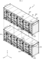
- FIG. 1 is a diagram showing an energy storage system 1 according to an embodiment of the present disclosure
- FIG. 2 is a perspective view showing the overall shape of a battery container 10 provided in the energy storage system 1 of FIG. 1
- FIG. 3 is a front view showing the battery container 10 of FIG. 2
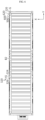
- FIG. 4 is a side view showing the battery container 10 of FIG. 2
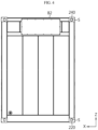
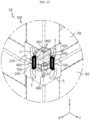
- FIG. 5 is a top view showing the battery container 10 of FIG. 2
- FIG. 6 is a bottom view showing the battery container 10 of FIG. 2 .
- FIGS. 3 to 6 exemplarily show only a second battery container B2, explained later.
- X-axis direction shown in the drawing may refer to a width direction
- Y-axis direction may refer to a length direction perpendicular to the X-axis direction on the horizontal plane (X-Y plane)
- Z-axis direction may refer to a vertical direction perpendicular to both the X-axis direction and the Y-axis direction.
- the energy storage system 1 includes a battery container 10.
- the energy storage system 1 may form a link group by combining a certain number of battery containers 10 and a control container (E-Link, EL). This will be explained in detail below.
- the battery container 10 described above may include a container body 100, a coupling unit 200, and a load support unit 300.
- the container body 100 may include a plurality of battery racks therein. To this end, the container body 100 may have an accommodation space to accommodate the battery racks described above. As an example, the container body 100 may be made of a metal material such as steel.
- the battery rack may be configured to include a plurality of battery modules stacked.
- each battery module may be configured to include a plurality of battery cells (secondary batteries) accommodated in a module case.
- the battery modules may be accommodated in a rack case and stacked in at least one direction.
- the battery modules may be configured to be stacked vertically through the rack case.
- the container body 100 may accommodate a plurality of battery modules therein by constructing a separate structure therein for fixing the plurality of battery modules, without including the battery rack described above.
- the coupling unit 200 may be configured to couple different container bodies 100.
- different container bodies 100 may be arranged to be stacked in a vertical direction. At least two container bodies 100 may be arranged to be stacked in a vertical direction. At this time, the container bodies 100 may be stacked in the vertical direction on the same ground.
- the container body 100 may, by way of example, include a first container body B1 and a second container body B2. At this time, the second container body B2 may be located lower than the first container body B 1. In particular, the second container body B2 may be located on the ground.
- the load support unit 300 may be configured to support the vertical load of the container body 100.
- the load support unit 300 may be provided in the form of a bracket, but is not limited thereto.
- the load support unit 300 may be integrally provided with the container body 100 or may be configured as a separate member.
- the load support unit 300 may be provided in a portion of the container body 100 that is different from the portion where the coupling unit 200 for coupling different container bodies 100 is located. Accordingly, the structural rigidity of the remaining portion of the container body 100, excluding the portion where the coupling unit 200 is located, may be reinforced.
- the vertical load of the container body 100 may be stably supported.
- the container bodies 100 may be stably stacked on the same ground, the energy density of the battery containers 10 may be improved in a limited ground.
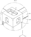
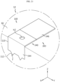
- FIG. 7 is an enlarged view showing the portion A of FIG. 2
- FIG. 8 is an enlarged view showing the portion B of FIG. 2
- FIG. 7 is a diagram showing a first coupling unit 220 provided at the bottom end of the first container body B1 in detail
- FIG. 8 is a diagram showing a second coupling unit 240 provided at the top end of the second container body B2 in detail.
- the coupling unit 200 may be provided to at least one of a top end and a bottom end of the container body 100.
- the coupling unit 200 may be provided only at one of the top end and the bottom end of the container body 100.
- the coupling unit 200 may be provided only at the bottom end of the first container body B1, and may be provided only at the top end of the second container body B2.
- the coupling unit 200 may be provided at both the top end and the bottom end of the container body 100.
- the coupling unit 200 may be provided at both the top end and the bottom end of the first container body B1, and may be provided at both the top end and the bottom end of the second container body B2.
- the coupling unit 200 provided at the bottom end of the second container body B2 may be located on the ground.
- the coupling unit 200 may include a first coupling unit 220 provided at the bottom end of the container body 100 and a second coupling unit 240 provided at the top end of the container body 100.
- the first coupling unit 220 and the second coupling unit 240 may be provided to both the first container body B1 and the second container body B2 described above.
- the first coupling unit 220 described above may also be provided at the bottom end of the second container body B2 located on the ground.
- the coupling unit 200 may be provided at a corner of the container body 100. More specifically, the first coupling unit 220 may be provided at the corner of the bottom end of the first container body B1 described above, and the second coupling unit 240 may be provided at the corner of the top end of the second container body B2 described above. At this time, the first coupling unit 220 and the second coupling unit 240 may be coupled to each other in the vertical direction.
- the coupling unit 200 may be provided at the corner of the container body 100, which is the part where stress is most concentrated, to stably couple different container bodies 100.
- the coupling unit 200 may be formed to extend further in the vertical direction than the top end or the bottom end of the container body 100. More specifically, the first coupling unit 220 may be formed to extend further downward than the bottom end of the first container body B1 described above, and the second coupling unit 240 may be formed to extend further upward than the top end of the second container body B2 described above.
- the coupling unit 200 is formed to extend further in the vertical direction than the top end or the bottom end of the container body 100, when different container bodies 100 are coupled, it is possible to prevent regions of different container bodies 100, except for the corners of the container bodies 100, from directly touching each other. Accordingly, it is possible to minimize the direct transfer of load to the battery modules arranged in the accommodation space of the container body 100.
- the load support unit 300 may be provided to at least one of the top end and the bottom end of the container body 100.
- the load support unit 300 may be provided only to one of the top end and the bottom end of the container body 100. As an example, the load support unit 300 may be provided only at the bottom end of the first container body B 1 described above, and may be provided only at the top end of the second container body B2 described above.
- the load support unit 300 may be provided at both the top end and the bottom end of the container body 100.
- the load support unit 300 may be provided at both the top end and the bottom end of the first container body B1, and may be provided at both the top end and the bottom end of the second container body B2.
- the load support unit 300 coupled to the bottom end of the second container body B2 may be located on the ground.
- the load support unit 300 may be configured to support the vertical load of two different container bodies 100.
- the load support unit 300 may additionally support the vertical load of the first container body B 1 and the second container body B2.
- the vertical load of the container bodies 100 may be stably supported.
- the load support unit 300 may be located between two different coupling units 200 on at least one of the upper surface and the lower surface of the container body 100.
- the load support unit 300 may be located between two different first coupling units 220 on the lower surface of the container body 100. At this time, the load support unit 300 may be located between two different first coupling units 220 in the length direction of the container body 100. In addition, although not shown, the load support unit 300 may be located between two different first coupling units 220 in the width direction of the container body 100, and may be located between two different first coupling units 220 located in the diagonal direction.
- the load support unit 300 may be located between two different second coupling units 240 on the upper surface of the container body 100. At this time, the load support unit 300 may be located between two different second coupling units 240 in the length direction of the container body 100. In addition, although not shown, the load support unit 300 may be located between two different second coupling units 240 in the width direction of the container body 100, and may be located between two different second coupling units 240 located in the diagonal direction.
- the load support unit 300 since the length in the length direction of the container body 100 is formed to be longer than the length in the width direction, if the load support unit 300 is located between two different coupling units 200 in the length direction of the container body 100, a higher load support effect may be achieved. In addition, since the load support unit 300 is located between two different coupling units 200 in all of the length direction, the width direction, and the diagonal direction of the container body 100, the vertical load of the container bodies 100 may be supported more stably.
- the load support unit 300 is located between the coupling units 200 that couple different container bodies 100 on at least one of the upper surface and the lower surface of the container body 100, the vertical load of the container bodies 100 may be supported more stably.
- the load support unit 300 may be formed in plurality between two different coupling units 200.
- a plurality of load support units 300 may be formed between two different coupling units 200 in the length direction of the container body 100.
- a plurality of load support units 300 may be formed between two different coupling units 200 in the width direction of the container body 100, and a plurality of load support units 300 may be formed between two different coupling units 200 located in the diagonal direction.
- the length in the length direction of the container body 100 is formed to be longer than the length in the width direction, if the plurality of load support units 300 are located between two different coupling units 200 in the length direction of the container body 100, a higher load support effect may be achieved.
- the plurality of load support units 300 are located between two different coupling units 200 in all of the length direction, the width direction, and the diagonal direction of the container body 100, the vertical load of the container body 100 may be supported more stably.
- the vertical load of the container bodies 100 may be distributed to the plurality of load support units 300. Accordingly, the vertical load of the container bodies 100 may be supported more stably.
- the load support unit 300 may be located between two different coupling units 200 at the edge of the container body 100.
- the load support unit 300 may be located between two different coupling units 200 at the edge in the length direction of the container body 100.
- the load support unit 300 may be located between two different coupling units 200 at the edge in the width direction of the container body 100.
- the load support unit 300 is located between two different coupling units 200 at the edge of the container body 100, which is vulnerable to the vertical load, the vertical load of the container body 100 may be supported more stably.
- the load support unit 300 may be located symmetrically at both sides of the edge of the container body 100 based on a center line of the edge of the container body 100.
- the load support unit 300 may be positioned symmetrically at both sides in the length direction based on the center line in the width direction at the edge of the container body 100 in the length direction.
- the load support unit 300 may be positioned symmetrically at both sides in the width direction based on the center line in the length direction, at the edge of the container body 100 in the width direction.
- the vertical load of the container body 100 may be uniformly distributed to the load support unit 300. Accordingly, the vertical load of the container body 100 may be supported more stably.
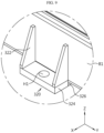
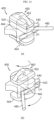
- FIG. 9 is an enlarged view showing the portion C of FIG. 2
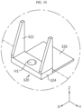
- FIG. 10 is a diagram showing a first support bracket 320 in FIG. 9 in detail
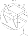
- FIG. 11 is an enlarged view showing the portion D of FIG. 2
- FIG. 12 is a diagram showing a second support bracket 340 in FIG. 11 in detail.
- the load support unit 300 may include a first support bracket 320 and a second support bracket 340.
- the first support bracket 320 may be provided at the bottom end of the container body 100. As an example, the first support bracket 320 may be provided at the bottom end of the first container body B1.
- the second support bracket 340 may be provided at the top end of the container body 100.
- the second support bracket 340 may be provided at the top end of the second container body B2.
- the second support bracket 340 may be configured to be coupled with the first support bracket 320 in the vertical direction.
- the first support bracket 320 and the second support bracket 340 may be configured to support the vertical load of the first container body B1 and the second container body B2.
- first support bracket 320 and the second support bracket 340 may be provided to both the first container body B 1 and the second container body B2 described above. Meanwhile, the first support bracket 320 described above may be provided at the bottom end of the second container body B2 located on the ground.
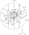
- FIG. 13 is an enlarged view showing the portion L of FIG. 1
- FIG. 14 is a diagram showing a connection member 400 in FIG. 13 in detail
- FIG. 15 is a diagram for illustrating a state in which a load support unit 300 supports the load of two different container bodies 100.
- the battery container 10 may further include a connection member 400 configured to connect two different coupling units 200 in the vertical direction.
- the connection member 400 is a type of twist lock and may be made of a high-strength metal material.
- connection member 400 may include a connection body 420 and a side portion 440.
- connection body 420 may be disposed vertically inside two different coupling units 200. That is, the connection body 420 may be disposed vertically inside the first coupling unit 220 provided to the first container body B1 and the second coupling unit 240 provided to the second container body B2.
- the side portion 440 may be formed at both sides of the connection body 420 and disposed between the two different coupling units 200 in the vertical direction. That is, the side portion 440 may be disposed between the first coupling unit 220 and the second coupling unit 240 in the vertical direction.
- connection member 400 A more detailed configuration of the connection member 400 described above will be described later in more detail.
- connection member 400 may prevent the two different coupling units 200 coupled to the corner of the container body 100, which is the part where stress is most concentrated in the container body 100, from directly touching each other. Accordingly, different container bodies 100 may be connected stably.
- first support bracket 320 and the second support bracket 340 of the present disclosure may be coupled to each other in the vertical direction and configured to support the vertical load of the first container body B1 and the second container body B2.
- the first support bracket 320 may include a first side bracket 322, a first coupling bracket 324, and a first base bracket 326.
- the first side bracket 322 may be coupled to a side surface of the bottom end of the container body 100. In this way, the first support bracket 320 may be more stably coupled to the container body 100 by providing the first side bracket 322 that is coupled to the side surface of the container body 100. Accordingly, the first support bracket 320 may support the vertical load of the container body 100 more stably.
- the first coupling bracket 324 may be coupled to the lower portion of the first side bracket 322 and configured to be coupled with the second support bracket 340 in the vertical direction. In this way, the first support bracket 320 may be more stably coupled to the second support bracket 340 in the vertical direction by providing the first coupling bracket 324 coupled to the lower portion of the first side bracket 322.
- the first base bracket 326 may be connected to the first coupling bracket 324 and configured to support the lower surface of the container body 100. In this way, the first support bracket 320 may support the vertical load of the container body 100 more stably by providing the first base bracket 326 configured to support the lower surface of the container body 100.
- the second support bracket 340 may include a second side bracket 342, a second coupling bracket 344, and a second base bracket 346.
- the second side bracket 342 may be coupled to a side surface of the top end of the container body 100.
- the second support bracket 340 may be more stably coupled to the container body 100 by providing the second side bracket 342 configured to be coupled to the side surface of the container body 100. Accordingly, the second support bracket 340 may support the vertical load of the container body 100 more stably.
- the second coupling bracket 344 may be coupled to the upper portion of the second side bracket 342 and configured to be coupled with the first coupling bracket 324 in the vertical direction.
- the first coupling bracket 324 and the second coupling bracket 344 may be coupled as a separate coupling member (not shown) couples a first hole H1 formed in the first coupling bracket 324 and a second hole H2 formed in the second coupling bracket 344 with each other.
- the second support bracket 340 may be more stably coupled to the first support bracket 320 in the vertical direction by providing the second coupling bracket 344 coupled to the upper portion of the second side bracket 342.
- the first support bracket 320 and the second support bracket 340 have the first coupling bracket 324 and the second coupling bracket 344 configured to be easily coupled to each other in the vertical direction, different container bodies 100 may be easily coupled.
- the second base bracket 346 may be connected to the second coupling bracket 344 and configured to support the upper surface of the container body 100. In this way, the second support bracket 340 may support the vertical load of the container body 100 more stably by providing the second base bracket 346 configured to support the upper surface of the container body 100.
- the gap between the bottom end of the first container body B 1 and the top end of the second container body B2 may be equal to the sum of the heights of the first base bracket 326 and the second base bracket 346. Accordingly, the deformation of the container body 100 may be minimized, and the vertical load of the container body 100 may be stably supported.
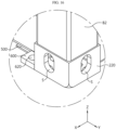
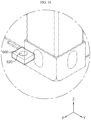
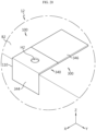
- FIG. 16 is an enlarged view of part E of FIG. 2
- FIG. 17 is a diagram showing a support plate 500 of FIG. 16 in detail
- FIG. 18 is a diagram showing a fixing member 600 of FIG. 16 in detail
- FIG. 19 is a diagram for illustrating the relationship between the support plate 500 and the load support unit 30 of FIG. 16 .
- the load support unit 300 may be configured to support the container body 100 disposed on the ground.
- the second container body B2 described above may be located on the ground.
- the first coupling unit 220 may be provided at the bottom end of the second container body B2 located on the ground.
- the first support bracket 320 of the load support unit 300 may be provided at the bottom end of the second container body B2 located on the ground.
- the bottom end of the first coupling bracket 324 and the first base bracket 326 of the first support bracket 320 may be located on the same horizontal plane as the bottom end of the first coupling unit 220.
- the first support bracket 320 may be fixed to the ground by inserting a separate coupling member (not shown) into the ground through the first hole H1 of the first coupling bracket 324. Accordingly, the second container body B2 located on the ground may be fixed to the ground.
- the load support unit 300 may stably support the container body 100 disposed on the ground, thereby enabling stable stacking of the container bodies 100.
- the battery container 10 may further include a support plate 500.
- the support plate 500 may be configured to support the container body 100 disposed on the ground.
- the support plate 500 may support the bottom end of the container body 100 disposed on the ground. More specifically, the support plate 500 may support the bottom end of the second container body B2 located on the ground.
- the support plate 500 may be directly connected to the first coupling unit 220 or may be disposed adjacent to the first coupling unit 220. By this configuration of the support plate 500, it is possible to additionally secure the support force in the vertical direction near the corner of the container body 100.
- the bottom end of the support plate 500 may be located on the same horizontal plane as the bottom end of the first coupling unit 220, and may be located on the same horizontal plane as the bottom end of the first coupling bracket 324 and the first base bracket 326 of the first support bracket 320.
- the battery container 10 may further include a fixing member 600.
- the fixing member 600 may be configured to connect the support plate 500 and the coupling unit 200. Since the support plate 500 and the coupling unit 200 are connected to each other by the fixing member 600 in this way, the support force in the vertical direction near the corner of the container body 100 may be more stably achieved.
- the fixing member 600 may be configured to fix the container body 100 to the ground. More specifically, the fixing member 600 may fix the second container body B2 located on the ground to the ground. As an example, a separate coupling member (not shown) may be inserted into the ground through a fixing hole 620 formed in the fixing member 600. Accordingly, the fixing member 600 may fix the second container body B2 located on the ground to the ground.
- the bottom end of the fixing member 600 may be located on the same horizontal plane as the bottom end of the first coupling unit 220, and may be located on the same horizontal plane as the bottom end of the support plate 500.
- the bottom end of the fixing member 600 may be located on the same horizontal plane as the bottom end of the first coupling bracket 324 and the first base bracket 326 of the first support bracket 320.
- the fixing member 600 by using the fixing member 600, not only more stable stacking of the container bodies 100 may be guided, but also an additional force for fixing the container bodies 100 to the ground may be secured.
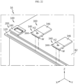
- FIGS. 20 to 23 are diagrams showing a battery container according to another embodiment of the present disclosure. Hereinafter, FIGS. 20 to 23 will show only some components of the battery container described above.
- the battery container 12 according to the second embodiment of the present disclosure is shown. Since the battery container 12 according to this embodiment is similar to the battery container 10 of the former embodiment, features substantially identical or similar to those of the former embodiment will not be described in detail, and features different from those of the former embodiment will be described in detail.
- the battery container 12 may include a container body 100 and a load support unit 300.
- At least one seating groove 110 may be formed at the top end of the second container body B2 described above along the length direction of the second container body B2.
- the seating groove 110 may be formed to be indented inward in the width direction of the second container body B2.
- the second coupling bracket 344 of the second support bracket 340 may be disposed in the seating groove 110.
- the second base bracket 346 of the second support bracket 340 may be connected to the second coupling bracket 344 and configured to support the upper surface of the second container body B2.
- the container body 100 may not include a second side bracket 342, unlike the former embodiment.
- the load support unit 300 may be configured more simply, and the load support unit 300 may support the vertical load of the container body 100 more stably.
- the battery container 14 according to the third embodiment of the present disclosure is shown. Since the battery container 14 according to this embodiment is similar to the battery container 10 of the former embodiment, features substantially identical or similar to those of the former embodiment will not be described in detail, and features different from those of the former embodiment will be described in detail.
- the battery container 14 may include a container body 100 and a load support unit 300.
- the second coupling bracket 344 of the second support bracket 340 may be disposed in the seating groove 110.
- a protrusion T having a shape corresponding to the guide groove 112 may be formed at one side of the second coupling bracket 344. The protrusion T may be inserted into the guide groove 112.
- the load support unit 300 may be positioned more stably in the seating groove 110, the load support unit 300 may support the vertical load of the container body 100 more stably.
- the battery container 16 according to the fourth embodiment of the present disclosure is shown. Since the battery container 16 according to this embodiment is similar to the battery container 10 of the former embodiment, features substantially identical or similar to those of the former embodiment will not be described in detail, and features different from those of the former embodiment will be described in detail.
- the battery container 16 may include a container body 100 and a load support unit 300.
- the container body 100 may further include a slide guide 120, unlike the former embodiment.
- the slide guide 120 may be formed on at least one of the top end and the bottom end of the container body 100.
- the slide guide 120 may be formed in the form of a guide rail.
- a plurality of load support units 300 may be arranged on the slide guide 120 and configured to move on the container body 100, and each load support unit 300 may be fixed at a specific position of the slide guide 120 by a separate stopper (not shown).
- the slide guide 120 may be formed at the top end of the second container body B2 described above along the length direction of the second container body B2.
- the second coupling bracket 344 may be configured to move on the second container body B2 along the slide guide 120, and each second coupling bracket 344 may be fixed at a specific position of the slide guide 120 by the stopper.
- the container body 100 may not include the second side bracket 342.
- the load support unit 300 may freely move on the container body 100 through the slide guide 120, the plurality of load support units 300 may be disposed at any positions of the container body 100. Accordingly, the vertical load of the container body 100 may be supported more stably.
- the battery container 18 according to the fifth embodiment of the present disclosure is shown. Since the battery container 18 according to this embodiment is similar to the battery container 10 of the former embodiment, features substantially identical or similar to those of the former embodiment will not be described in detail, and features different from those of the former embodiment will be described in detail.
- the battery container 18 may include a container body 100 and a coupling unit 200.
- the coupling unit 200 may further have a side hole S.
- the side hole S may be formed in the side surface of the coupling unit 200 along the vertical direction.
- the battery container 18 according to this embodiment may further include a reinforcing member 700, unlike the former embodiment.
- the reinforcing member 700 may connect the side holes S of two different coupling units 200 in the vertical direction.
- the reinforcing member 700 may connect the side hole S formed in the side surface of the first coupling unit 220 coupled to the first container body B1 and the side hole S formed in the side surface of the second coupling unit 240 coupled to the second container body B2 in the vertical direction.
- the reinforcing member 700 may be made of an elastic material and may be formed in a clip shape to facilitate attachment and detachment to/from the side hole S.
- the support force in the vertical direction may be additionally secured at the corner of the container body 100, and also more stable stacking of the container bodies 100 may be guided.
- the vertical load of the container bodies 100 may be stably supported.
- connection member 400 may further include a locking unit 460 and a handle portion 480.
- the locking unit 460 may be configured to fix the connection body 420 of the connection member 400 to the interior of the coupling units 200.
- the handle portion 480 may be connected to the locking unit 460 and may have a long bar shape.
- the handle portion 480 may be configured to rotate the locking unit 460 with respect to the connection body 420 according to movement on a horizontal plane within an elongated hole LH formed at one side of the connection body 420.
- the handle portion 480 may act to fix the connection body 420 to the interior of the coupling units 200 through the locking unit 460 by rotating the locking unit 460 with respect to the connection body 420.
- the locking unit 460 may include a first locking member 462, a second locking member 464, and a rotary shaft 466.
- the first locking member 462 may be disposed at the upper portion of the connection body 420.
- the second locking member 464 may be disposed at the lower portion of the connection body 420.
- the rotary shaft 466 may be formed inside the connection body 420 and connect the first locking member 462 and the second locking member 464.
- the coupling unit 200 described above may further include a perforated hole G.
- the perforated hole G is formed at one side of the coupling unit 200 in the vertical direction, and the first locking member 462 or the second locking member 464 may pass through the perforated hole G.
- the first locking member 462 and the second locking member 464 may be converted from the state of FIG. 14(a) to FIG. 14(b) , so as to be arranged in a direction perpendicular to the perforated hole G inside the coupling units 200. In this state, the first locking member 462 and the second locking member 464 may be prevented from passing through the perforated hole G. Accordingly, the connection body 420 may be fixed inside the coupling units 200.
- At least one battery containers 10, 12, 14, 16, 18 described above may be provided to form an energy storage system 1.
- the energy storage system 1 may form a link group by combining a certain number of battery containers 10 and a control container EL.
- two container bodies 100 and one control container EL are provided.
- two container bodies 100 and one control container EL may constitute one link group.
- the present disclosure is not limited thereto, and when three or more container bodies 100 are stacked, it is also possible that three or more container bodies 100 and one control container EL form one link group.
- each link group the container body 100 located on the ground may be connected to one control container EL.
- the control container EL may perform overall control or diagnosis for the container bodies 100 that are stacked.
- control container EL may include a DC part, an AC part, and a BSC part to control the battery container. Meanwhile, each control container EL may be connected to the PCS.
Landscapes
- Chemical & Material Sciences (AREA)
- Chemical Kinetics & Catalysis (AREA)
- Electrochemistry (AREA)
- General Chemical & Material Sciences (AREA)
- Battery Mounting, Suspending (AREA)
Abstract
Description
- The present disclosure relates to a battery container and an energy storage system including the same, and more specifically, to a battery container with improved energy density and an energy storage system including the same. The present application claims priority to
Korean Patent Application No. 10-2022-0055923 filed on May 6, 2022 - Currently commercialized secondary batteries include nickel cadmium batteries, nickel hydrogen batteries, nickel zinc batteries, and lithium secondary batteries. Among them, lithium secondary batteries are in the spotlight since they can be freely charged and discharged due to little memory effect compared to nickel-based secondary batteries and have very low discharge rate and high energy density.
- The lithium secondary battery mainly uses lithium-based oxide and carbon material as a positive electrode active material and a negative electrode active material, respectively. The lithium secondary battery includes an electrode assembly in which a positive electrode plate and a negative electrode plate coated with a positive electrode active material and a negative electrode active material are disposed with a separator interposed therebetween, and an exterior, namely a battery case, that seals and accommodates the electrode assembly along with an electrolyte solution.
- Generally, lithium secondary batteries may be classified into can-type secondary batteries in which the electrode assembly is included in a metal can and pouch-type secondary batteries in which the electrode assembly is included in a pouch of an aluminum laminate sheet, depending on the shape of the exterior.
- The secondary battery may be used alone, but in many cases, the secondary battery is generally configured to include a plurality of secondary batteries electrically connected to each other in series and/or parallel. In particular, a plurality of secondary batteries may be electrically connected to each other and accommodated inside one module case to form one battery module. In addition, the battery module may be used alone, or two or more battery modules may be electrically connected to each other in series and/or parallel to form a higher-level device such as a battery rack or a battery pack.
- Recently, as issues such as power shortage and eco-friendly energy have emerged, an energy storage system (ESS) for storing generated power is receiving more attention. For example, the smart grid system is being proposed as one of ways to control power supply and demand. The amount of electricity used by consumers is not always constant and may fluctuate from time to time. A representative example is that the amount of power usage increases rapidly during the summer afternoon due to the use of air conditioning devices, and then rapidly decreases at night. In this way, in view of power consumers, the power consumption is not constant and may fluctuate frequently, but in view of power suppliers, even if the power generation is controlled to some extent, it is realistically difficult to match such power consumption. Therefore, due to the imbalance between power supply and consumption, surplus power supply or power supply shortage may occur, and the smart grid system may flexibly store and control power to solve such problems. The smart grid system may be regarded as a concept that stores power at time points or areas in which surplus power is generated and supplies the stored power at time points or areas in which power shortage occurs. One of key components to construct such a smart grid system may be an energy storage system for storing power. In addition, as the commercialization of electric vehicles progresses in earnest in recent years, power storage devices may be utilized in facilities for charging electric vehicles, such as charging stations.
- The energy storage system may be typically configured to include a large number of battery containers to secure a huge charging and discharging capacity. In addition, each battery container may include a plurality of battery racks, and each battery rack may include a plurality of battery modules.
- The battery container may require a variety of performances. In particular, in the energy storage system (ESS), a plurality of battery containers may be installed to be connected to each other. However, in the conventional energy storage system, there is no connection and load support structure for stacking a plurality of battery containers, so it is difficult to configure more battery containers when the ground for placing battery containers is limited.
- The present disclosure is designed to solve the problems of the related art, and therefore the present disclosure is directed to providing a battery container with improved energy density for a limited ground, and an energy storage system including the same.
- However, the technical problem to be solved by the present disclosure is not limited to the above, and other problems not mentioned herein will be clearly understood by those skilled in the art from the following disclosure.
- In one aspect of the present disclosure, there is provided a battery container, comprising: a container body; a coupling unit configured to couple different container bodies; and a load support unit configured to support a vertical load of the container body.
- Preferably, the coupling unit may be provided to at least one of a top end and a bottom end of the container body and provided at a corner of the container body.
- Preferably, the coupling unit may be formed to extend further in a vertical direction than the top end or the bottom end of the container body.
- Preferably, the load support unit may be provided to at least one of a top end and a bottom end of the container body and configured to support the vertical load of two different container bodies.
- Preferably, the load support unit may include a first support bracket provided at the bottom end of the container body; and a second support bracket provided at the top end of the container body and configured to be coupled with the first support bracket in a vertical direction.
- Preferably, the first support bracket may include a first side bracket coupled to a side surface of the bottom end of the container body; a first coupling bracket coupled to a lower portion of the first side bracket and configured to be coupled with the second support bracket in the vertical direction; and a first base bracket connected to the first coupling bracket and configured to support a lower surface of the container body.
- Preferably, the second support bracket may include a second side bracket coupled to a side surface of the top end of the container body; a second coupling bracket coupled to an upper portion of the second side bracket and configured to be coupled with the first coupling bracket in the vertical direction; and a second base bracket connected to the second coupling bracket and configured to support an upper surface of the container body.
- Preferably, the load support unit may be located between two different coupling units on at least one of an upper surface and a lower surface of the container body.
- Preferably, the load support unit may be formed in plurality between the two different coupling units.
- Preferably, the load support unit may be located between the two different coupling units at an edge of the container body.
- Preferably, the load support unit may be located symmetrically at both sides of an edge of the container body based on a center line of the edge of the container body.
- Preferably, the load support unit may be configured to support the container body disposed on the ground.
- Preferably, the battery container may further comprise a support plate configured to support the container body disposed on the ground.
- Preferably, the battery container may further comprise a fixing member configured to connect the support plate and the coupling unit, and the fixing member may be configured to fix the container body to the ground.
- Preferably, the coupling unit may further include a side hole in a side surface of the coupling unit formed along the vertical direction, and the battery container may further comprise a reinforcing member configured to connect the side holes of the two different coupling units in the vertical direction.
- In another aspect of the present disclosure, there is also provided an energy storage system, comprising at least one battery container as described above.
- According to an embodiment of the present disclosure, when different container bodies are coupled in the vertical direction, the vertical load of the container body may be stably supported.
- In addition, according to an embodiment of the present disclosure, since container bodies may be stably stacked on the same ground, the energy density of the battery containers may be improved for a limited ground.
- In addition, several other additional effects may be achieved by various embodiments of the present disclosure. Various effects of the present disclosure will be described in detail in each embodiment, or the effects that can be easily understood by those skilled in the art will be not be described in detail.
- The accompanying drawings illustrate a preferred embodiment of the present disclosure and together with the foregoing disclosure, serve to provide further understanding of the technical features of the present disclosure, and thus, the present disclosure is not construed as being limited to the drawing.
-
FIG. 1 is a diagram showing an energy storage system according to an embodiment of the present disclosure. -
FIG. 2 is a perspective view showing the overall shape of a battery container provided in the energy storage system ofFIG. 1 . -
FIG. 3 is a front view showing the battery container ofFIG. 2 . -
FIG. 4 is a side view showing the battery container ofFIG. 2 . -
FIG. 5 is a top view showing the battery container ofFIG. 2 . -
FIG. 6 is a bottom view showing the battery container ofFIG. 2 . -
FIG. 7 is an enlarged view showing the portion A ofFIG. 2 . -
FIG. 8 is an enlarged view showing the portion B ofFIG. 2 . -
FIG. 9 is an enlarged view showing the portion C ofFIG. 2 . -
FIG. 10 is a diagram showing a first support bracket inFIG. 9 in detail. -
FIG. 11 is an enlarged view showing the portion D ofFIG. 2 . -
FIG. 12 is a diagram showing a second support bracket inFIG. 11 in detail. -
FIG. 13 is an enlarged view showing the portion L ofFIG. 1 . -
FIG. 14 is a diagram showing a connection member inFIG. 13 in detail. -
FIG. 15 is a diagram for illustrating a state in which a load support unit supports the load of two different container bodies. -
FIG. 16 is an enlarged view of part E ofFIG. 2 . -
FIG. 17 is a diagram showing a support plate ofFIG. 16 in detail. -
FIG. 18 is a diagram showing a fixing member ofFIG. 16 in detail. -
FIG. 19 is a diagram for illustrating the relationship between the support plate and the load support unit ofFIG. 16 . -
FIGS. 20 to 23 are diagrams showing a battery container according to another embodiment of the present disclosure. - Hereinafter, preferred embodiments of the present disclosure will be described in detail with reference to the accompanying drawings. Prior to the description, it should be understood that the terms used in the specification and the appended claims should not be construed as limited to general and dictionary meanings, but interpreted based on the meanings and concepts corresponding to technical aspects of the present disclosure on the basis of the principle that the inventor is allowed to define terms appropriately for the best explanation.
- Therefore, the description proposed herein is just a preferable example for the purpose of illustrations only, not intended to limit the scope of the disclosure, so it should be understood that other equivalents and modifications could be made thereto without departing from the scope of the disclosure.
-
FIG. 1 is a diagram showing anenergy storage system 1 according to an embodiment of the present disclosure,FIG. 2 is a perspective view showing the overall shape of abattery container 10 provided in theenergy storage system 1 ofFIG. 1 ,FIG. 3 is a front view showing thebattery container 10 ofFIG. 2 ,FIG. 4 is a side view showing thebattery container 10 ofFIG. 2 ,FIG. 5 is a top view showing thebattery container 10 ofFIG. 2 , andFIG. 6 is a bottom view showing thebattery container 10 ofFIG. 2 . At this time,FIGS. 3 to 6 exemplarily show only a second battery container B2, explained later. - In the embodiment of the present disclosure, X-axis direction shown in the drawing may refer to a width direction, Y-axis direction may refer to a length direction perpendicular to the X-axis direction on the horizontal plane (X-Y plane), and Z-axis direction may refer to a vertical direction perpendicular to both the X-axis direction and the Y-axis direction.
- Referring to
FIGS. 1 to 6 , theenergy storage system 1 according to an embodiment of the present disclosure includes abattery container 10. - The
energy storage system 1 may form a link group by combining a certain number ofbattery containers 10 and a control container (E-Link, EL). This will be explained in detail below. - The
battery container 10 described above may include acontainer body 100, acoupling unit 200, and aload support unit 300. - The
container body 100 may include a plurality of battery racks therein. To this end, thecontainer body 100 may have an accommodation space to accommodate the battery racks described above. As an example, thecontainer body 100 may be made of a metal material such as steel. - The battery rack may be configured to include a plurality of battery modules stacked. Here, each battery module may be configured to include a plurality of battery cells (secondary batteries) accommodated in a module case. In addition, the battery modules may be accommodated in a rack case and stacked in at least one direction. For example, the battery modules may be configured to be stacked vertically through the rack case.
- Alternatively, the
container body 100 may accommodate a plurality of battery modules therein by constructing a separate structure therein for fixing the plurality of battery modules, without including the battery rack described above. - The
coupling unit 200 may be configured to coupledifferent container bodies 100. - In one embodiment,
different container bodies 100 may be arranged to be stacked in a vertical direction. At least twocontainer bodies 100 may be arranged to be stacked in a vertical direction. At this time, thecontainer bodies 100 may be stacked in the vertical direction on the same ground. - The
container body 100 may, by way of example, include a first container body B1 and a second container body B2. At this time, the second container body B2 may be located lower than the firstcontainer body B 1. In particular, the second container body B2 may be located on the ground. - The
load support unit 300 may be configured to support the vertical load of thecontainer body 100. As an example, theload support unit 300 may be provided in the form of a bracket, but is not limited thereto. In addition, theload support unit 300 may be integrally provided with thecontainer body 100 or may be configured as a separate member. - The
load support unit 300 may be provided in a portion of thecontainer body 100 that is different from the portion where thecoupling unit 200 for couplingdifferent container bodies 100 is located. Accordingly, the structural rigidity of the remaining portion of thecontainer body 100, excluding the portion where thecoupling unit 200 is located, may be reinforced. - According to this embodiment of the present disclosure, when
different container bodies 100 are coupled in the vertical direction, the vertical load of thecontainer body 100 may be stably supported. - In addition, since the
container bodies 100 may be stably stacked on the same ground, the energy density of thebattery containers 10 may be improved in a limited ground. - Hereinafter, the
coupling unit 200 and theload support unit 300 will be described in more detail. -
FIG. 7 is an enlarged view showing the portion A ofFIG. 2 , andFIG. 8 is an enlarged view showing the portion B ofFIG. 2 . Here,FIG. 7 is a diagram showing afirst coupling unit 220 provided at the bottom end of the first container body B1 in detail, andFIG. 8 is a diagram showing asecond coupling unit 240 provided at the top end of the second container body B2 in detail. - Referring to
FIGS. 1 to 8 , thecoupling unit 200 may be provided to at least one of a top end and a bottom end of thecontainer body 100. - The
coupling unit 200 may be provided only at one of the top end and the bottom end of thecontainer body 100. For example, thecoupling unit 200 may be provided only at the bottom end of the first container body B1, and may be provided only at the top end of the second container body B2. - Alternatively, the
coupling unit 200 may be provided at both the top end and the bottom end of thecontainer body 100. As an example, thecoupling unit 200 may be provided at both the top end and the bottom end of the first container body B1, and may be provided at both the top end and the bottom end of the second container body B2. At this time, thecoupling unit 200 provided at the bottom end of the second container body B2 may be located on the ground. - The
coupling unit 200 may include afirst coupling unit 220 provided at the bottom end of thecontainer body 100 and asecond coupling unit 240 provided at the top end of thecontainer body 100. At this time, thefirst coupling unit 220 and thesecond coupling unit 240 may be provided to both the first container body B1 and the second container body B2 described above. Meanwhile, thefirst coupling unit 220 described above may also be provided at the bottom end of the second container body B2 located on the ground. - In addition, the
coupling unit 200 may be provided at a corner of thecontainer body 100. More specifically, thefirst coupling unit 220 may be provided at the corner of the bottom end of the first container body B1 described above, and thesecond coupling unit 240 may be provided at the corner of the top end of the second container body B2 described above. At this time, thefirst coupling unit 220 and thesecond coupling unit 240 may be coupled to each other in the vertical direction. - In this way, the
coupling unit 200 may be provided at the corner of thecontainer body 100, which is the part where stress is most concentrated, to stably coupledifferent container bodies 100. - In addition, the
coupling unit 200 may be formed to extend further in the vertical direction than the top end or the bottom end of thecontainer body 100. More specifically, thefirst coupling unit 220 may be formed to extend further downward than the bottom end of the first container body B1 described above, and thesecond coupling unit 240 may be formed to extend further upward than the top end of the second container body B2 described above. - In this way, since the
coupling unit 200 is formed to extend further in the vertical direction than the top end or the bottom end of thecontainer body 100, whendifferent container bodies 100 are coupled, it is possible to prevent regions ofdifferent container bodies 100, except for the corners of thecontainer bodies 100, from directly touching each other. Accordingly, it is possible to minimize the direct transfer of load to the battery modules arranged in the accommodation space of thecontainer body 100. - Referring to
FIGS. 1 to 6 again, theload support unit 300 may be provided to at least one of the top end and the bottom end of thecontainer body 100. - The
load support unit 300 may be provided only to one of the top end and the bottom end of thecontainer body 100. As an example, theload support unit 300 may be provided only at the bottom end of the firstcontainer body B 1 described above, and may be provided only at the top end of the second container body B2 described above. - Alternatively, the
load support unit 300 may be provided at both the top end and the bottom end of thecontainer body 100. As an example, theload support unit 300 may be provided at both the top end and the bottom end of the first container body B1, and may be provided at both the top end and the bottom end of the second container body B2. At this time, theload support unit 300 coupled to the bottom end of the second container body B2 may be located on the ground. - The
load support unit 300 may be configured to support the vertical load of twodifferent container bodies 100. - More specifically, when the first container body B1 and the container body B2 described above are coupled to each other by the
first coupling unit 220 and thesecond coupling unit 240, theload support unit 300 may additionally support the vertical load of the firstcontainer body B 1 and the second container body B2. - According to this embodiment of the present disclosure, when two
different container bodies 100 are coupled in the vertical direction, the vertical load of thecontainer bodies 100 may be stably supported. - In addition, the
load support unit 300 may be located between twodifferent coupling units 200 on at least one of the upper surface and the lower surface of thecontainer body 100. - More specifically, the
load support unit 300 may be located between two differentfirst coupling units 220 on the lower surface of thecontainer body 100. At this time, theload support unit 300 may be located between two differentfirst coupling units 220 in the length direction of thecontainer body 100. In addition, although not shown, theload support unit 300 may be located between two differentfirst coupling units 220 in the width direction of thecontainer body 100, and may be located between two differentfirst coupling units 220 located in the diagonal direction. - In addition, the
load support unit 300 may be located between two differentsecond coupling units 240 on the upper surface of thecontainer body 100. At this time, theload support unit 300 may be located between two differentsecond coupling units 240 in the length direction of thecontainer body 100. In addition, although not shown, theload support unit 300 may be located between two differentsecond coupling units 240 in the width direction of thecontainer body 100, and may be located between two differentsecond coupling units 240 located in the diagonal direction. - For example, as shown in
FIGS. 1 to 6 , since the length in the length direction of thecontainer body 100 is formed to be longer than the length in the width direction, if theload support unit 300 is located between twodifferent coupling units 200 in the length direction of thecontainer body 100, a higher load support effect may be achieved. In addition, since theload support unit 300 is located between twodifferent coupling units 200 in all of the length direction, the width direction, and the diagonal direction of thecontainer body 100, the vertical load of thecontainer bodies 100 may be supported more stably. - According to this embodiment of the present disclosure, since the
load support unit 300 is located between thecoupling units 200 that coupledifferent container bodies 100 on at least one of the upper surface and the lower surface of thecontainer body 100, the vertical load of thecontainer bodies 100 may be supported more stably. - In particular, the
load support unit 300 may be formed in plurality between twodifferent coupling units 200. For example, a plurality ofload support units 300 may be formed between twodifferent coupling units 200 in the length direction of thecontainer body 100. In addition, although not shown, a plurality ofload support units 300 may be formed between twodifferent coupling units 200 in the width direction of thecontainer body 100, and a plurality ofload support units 300 may be formed between twodifferent coupling units 200 located in the diagonal direction. - Also, as shown in
FIGS. 1 to 6 , since the length in the length direction of thecontainer body 100 is formed to be longer than the length in the width direction, if the plurality ofload support units 300 are located between twodifferent coupling units 200 in the length direction of thecontainer body 100, a higher load support effect may be achieved. In addition, since the plurality ofload support units 300 are located between twodifferent coupling units 200 in all of the length direction, the width direction, and the diagonal direction of thecontainer body 100, the vertical load of thecontainer body 100 may be supported more stably. - According to this embodiment of the present disclosure, since a plurality of
load support units 300 are formed between thecoupling units 200 that coupledifferent container bodies 100, the vertical load of thecontainer bodies 100 may be distributed to the plurality ofload support units 300. Accordingly, the vertical load of thecontainer bodies 100 may be supported more stably. - In addition, the
load support unit 300 may be located between twodifferent coupling units 200 at the edge of thecontainer body 100. - More specifically, the
load support unit 300 may be located between twodifferent coupling units 200 at the edge in the length direction of thecontainer body 100. In addition, although not shown, theload support unit 300 may be located between twodifferent coupling units 200 at the edge in the width direction of thecontainer body 100. - According to this embodiment of the present disclosure, since the
load support unit 300 is located between twodifferent coupling units 200 at the edge of thecontainer body 100, which is vulnerable to the vertical load, the vertical load of thecontainer body 100 may be supported more stably. - In addition, the
load support unit 300 may be located symmetrically at both sides of the edge of thecontainer body 100 based on a center line of the edge of thecontainer body 100. - More specifically, the
load support unit 300 may be positioned symmetrically at both sides in the length direction based on the center line in the width direction at the edge of thecontainer body 100 in the length direction. In addition, although not shown, theload support unit 300 may be positioned symmetrically at both sides in the width direction based on the center line in the length direction, at the edge of thecontainer body 100 in the width direction. - According to this embodiment of the present disclosure, the vertical load of the
container body 100 may be uniformly distributed to theload support unit 300. Accordingly, the vertical load of thecontainer body 100 may be supported more stably. -
FIG. 9 is an enlarged view showing the portion C ofFIG. 2 ,FIG. 10 is a diagram showing afirst support bracket 320 inFIG. 9 in detail,FIG. 11 is an enlarged view showing the portion D ofFIG. 2 , andFIG. 12 is a diagram showing asecond support bracket 340 inFIG. 11 in detail. - Referring to
FIGS. 1 to 6 and9 to 12 , theload support unit 300 may include afirst support bracket 320 and asecond support bracket 340. - The
first support bracket 320 may be provided at the bottom end of thecontainer body 100. As an example, thefirst support bracket 320 may be provided at the bottom end of the first container body B1. - The
second support bracket 340 may be provided at the top end of thecontainer body 100. As an example, thesecond support bracket 340 may be provided at the top end of the second container body B2. Also, thesecond support bracket 340 may be configured to be coupled with thefirst support bracket 320 in the vertical direction. - The
first support bracket 320 and thesecond support bracket 340 may be configured to support the vertical load of the first container body B1 and the second container body B2. - At this time, the
first support bracket 320 and thesecond support bracket 340 may be provided to both the firstcontainer body B 1 and the second container body B2 described above. Meanwhile, thefirst support bracket 320 described above may be provided at the bottom end of the second container body B2 located on the ground. -
FIG. 13 is an enlarged view showing the portion L ofFIG. 1 ,FIG. 14 is a diagram showing aconnection member 400 inFIG. 13 in detail, andFIG. 15 is a diagram for illustrating a state in which aload support unit 300 supports the load of twodifferent container bodies 100. - Referring to
FIGS. 13 to 15 , thebattery container 10 may further include aconnection member 400 configured to connect twodifferent coupling units 200 in the vertical direction. As an example, theconnection member 400 is a type of twist lock and may be made of a high-strength metal material. - The
connection member 400 may include aconnection body 420 and aside portion 440. - The
connection body 420 may be disposed vertically inside twodifferent coupling units 200. That is, theconnection body 420 may be disposed vertically inside thefirst coupling unit 220 provided to the first container body B1 and thesecond coupling unit 240 provided to the second container body B2. - The
side portion 440 may be formed at both sides of theconnection body 420 and disposed between the twodifferent coupling units 200 in the vertical direction. That is, theside portion 440 may be disposed between thefirst coupling unit 220 and thesecond coupling unit 240 in the vertical direction. - A more detailed configuration of the
connection member 400 described above will be described later in more detail. - By the
side portion 440, theconnection member 400 may prevent the twodifferent coupling units 200 coupled to the corner of thecontainer body 100, which is the part where stress is most concentrated in thecontainer body 100, from directly touching each other. Accordingly,different container bodies 100 may be connected stably. - Meanwhile, in a state where the
side portion 440 is disposed between the twodifferent coupling units 200, downward sagging may occur in the region of the first container body B1 excluding the area between the twodifferent coupling units 200. At this time, thefirst support bracket 320 and thesecond support bracket 340 of the present disclosure may be coupled to each other in the vertical direction and configured to support the vertical load of the first container body B1 and the second container body B2. - According to this embodiment of the present disclosure, when two
different container bodies 100 are coupled in the vertical direction, deformation of thecontainer body 100 may be minimized and the vertical load of thecontainer body 100 may be stably supported. - Referring to
FIGS. 9 to 15 again, thefirst support bracket 320 may include afirst side bracket 322, afirst coupling bracket 324, and afirst base bracket 326. - The
first side bracket 322 may be coupled to a side surface of the bottom end of thecontainer body 100. In this way, thefirst support bracket 320 may be more stably coupled to thecontainer body 100 by providing thefirst side bracket 322 that is coupled to the side surface of thecontainer body 100. Accordingly, thefirst support bracket 320 may support the vertical load of thecontainer body 100 more stably. - The
first coupling bracket 324 may be coupled to the lower portion of thefirst side bracket 322 and configured to be coupled with thesecond support bracket 340 in the vertical direction. In this way, thefirst support bracket 320 may be more stably coupled to thesecond support bracket 340 in the vertical direction by providing thefirst coupling bracket 324 coupled to the lower portion of thefirst side bracket 322. - The
first base bracket 326 may be connected to thefirst coupling bracket 324 and configured to support the lower surface of thecontainer body 100. In this way, thefirst support bracket 320 may support the vertical load of thecontainer body 100 more stably by providing thefirst base bracket 326 configured to support the lower surface of thecontainer body 100. - In addition, the
second support bracket 340 may include asecond side bracket 342, asecond coupling bracket 344, and asecond base bracket 346. - The
second side bracket 342 may be coupled to a side surface of the top end of thecontainer body 100. In this way, thesecond support bracket 340 may be more stably coupled to thecontainer body 100 by providing thesecond side bracket 342 configured to be coupled to the side surface of thecontainer body 100. Accordingly, thesecond support bracket 340 may support the vertical load of thecontainer body 100 more stably. - The
second coupling bracket 344 may be coupled to the upper portion of thesecond side bracket 342 and configured to be coupled with thefirst coupling bracket 324 in the vertical direction. As an example, thefirst coupling bracket 324 and thesecond coupling bracket 344 may be coupled as a separate coupling member (not shown) couples a first hole H1 formed in thefirst coupling bracket 324 and a second hole H2 formed in thesecond coupling bracket 344 with each other. - In this way, the
second support bracket 340 may be more stably coupled to thefirst support bracket 320 in the vertical direction by providing thesecond coupling bracket 344 coupled to the upper portion of thesecond side bracket 342. In addition, since thefirst support bracket 320 and thesecond support bracket 340 have thefirst coupling bracket 324 and thesecond coupling bracket 344 configured to be easily coupled to each other in the vertical direction,different container bodies 100 may be easily coupled. - The
second base bracket 346 may be connected to thesecond coupling bracket 344 and configured to support the upper surface of thecontainer body 100. In this way, thesecond support bracket 340 may support the vertical load of thecontainer body 100 more stably by providing thesecond base bracket 346 configured to support the upper surface of thecontainer body 100. - Meanwhile, in a state where the
side portion 440 is disposed between the twodifferent coupling units 200, the gap between the bottom end of the firstcontainer body B 1 and the top end of the second container body B2 may be equal to the sum of the heights of thefirst base bracket 326 and thesecond base bracket 346. Accordingly, the deformation of thecontainer body 100 may be minimized, and the vertical load of thecontainer body 100 may be stably supported. -
FIG. 16 is an enlarged view of part E ofFIG. 2 ,FIG. 17 is a diagram showing asupport plate 500 ofFIG. 16 in detail,FIG. 18 is a diagram showing a fixingmember 600 ofFIG. 16 in detail, andFIG. 19 is a diagram for illustrating the relationship between thesupport plate 500 and the load support unit 30 ofFIG. 16 . - Referring to
FIGS. 9 to 12 and16 to 19 , theload support unit 300 may be configured to support thecontainer body 100 disposed on the ground. - More specifically, the second container body B2 described above may be located on the ground. At this time, among the
coupling units 200, thefirst coupling unit 220 may be provided at the bottom end of the second container body B2 located on the ground. In addition, thefirst support bracket 320 of theload support unit 300 may be provided at the bottom end of the second container body B2 located on the ground. - In particular, the bottom end of the
first coupling bracket 324 and thefirst base bracket 326 of thefirst support bracket 320 may be located on the same horizontal plane as the bottom end of thefirst coupling unit 220. Also, thefirst support bracket 320 may be fixed to the ground by inserting a separate coupling member (not shown) into the ground through the first hole H1 of thefirst coupling bracket 324. Accordingly, the second container body B2 located on the ground may be fixed to the ground. - According to this embodiment of the present disclosure, the
load support unit 300 may stably support thecontainer body 100 disposed on the ground, thereby enabling stable stacking of thecontainer bodies 100. - Meanwhile, the
battery container 10 may further include asupport plate 500. Thesupport plate 500 may be configured to support thecontainer body 100 disposed on the ground. - At this time, the
support plate 500 may support the bottom end of thecontainer body 100 disposed on the ground. More specifically, thesupport plate 500 may support the bottom end of the second container body B2 located on the ground. - In particular, the
support plate 500 may be directly connected to thefirst coupling unit 220 or may be disposed adjacent to thefirst coupling unit 220. By this configuration of thesupport plate 500, it is possible to additionally secure the support force in the vertical direction near the corner of thecontainer body 100. - In addition, the bottom end of the
support plate 500 may be located on the same horizontal plane as the bottom end of thefirst coupling unit 220, and may be located on the same horizontal plane as the bottom end of thefirst coupling bracket 324 and thefirst base bracket 326 of thefirst support bracket 320. - According to this embodiment of the present disclosure, since the
support plate 500 is configured to additionally support thecontainer body 100 disposed on the ground in addition to theload support unit 300, it is possible to guide more stable stacking of thecontainer bodies 100. - Referring to
FIGS. 16 to 19 again, thebattery container 10 may further include a fixingmember 600. - The fixing
member 600 may be configured to connect thesupport plate 500 and thecoupling unit 200. Since thesupport plate 500 and thecoupling unit 200 are connected to each other by the fixingmember 600 in this way, the support force in the vertical direction near the corner of thecontainer body 100 may be more stably achieved. - In addition, the fixing
member 600 may be configured to fix thecontainer body 100 to the ground. More specifically, the fixingmember 600 may fix the second container body B2 located on the ground to the ground. As an example, a separate coupling member (not shown) may be inserted into the ground through a fixinghole 620 formed in the fixingmember 600. Accordingly, the fixingmember 600 may fix the second container body B2 located on the ground to the ground. - At this time, the bottom end of the fixing
member 600 may be located on the same horizontal plane as the bottom end of thefirst coupling unit 220, and may be located on the same horizontal plane as the bottom end of thesupport plate 500. In addition, the bottom end of the fixingmember 600 may be located on the same horizontal plane as the bottom end of thefirst coupling bracket 324 and thefirst base bracket 326 of thefirst support bracket 320. - According to this embodiment of the present disclosure, by using the fixing
member 600, not only more stable stacking of thecontainer bodies 100 may be guided, but also an additional force for fixing thecontainer bodies 100 to the ground may be secured. -
FIGS. 20 to 23 are diagrams showing a battery container according to another embodiment of the present disclosure. Hereinafter,FIGS. 20 to 23 will show only some components of the battery container described above. - Referring to
FIG. 20 , thebattery container 12 according to the second embodiment of the present disclosure is shown. Since thebattery container 12 according to this embodiment is similar to thebattery container 10 of the former embodiment, features substantially identical or similar to those of the former embodiment will not be described in detail, and features different from those of the former embodiment will be described in detail. - Referring to
FIG. 20 , thebattery container 12 may include acontainer body 100 and aload support unit 300. - In the
battery container 12 according to this embodiment, thecontainer body 100 may further include aseating groove 110, unlike the former embodiment. Theseating groove 110 may be formed on at least one of the top end and the bottom end of thecontainer body 100. In addition, theload support unit 300 may be located in theseating groove 110. - As an example, at least one
seating groove 110 may be formed at the top end of the second container body B2 described above along the length direction of the second container body B2. Theseating groove 110 may be formed to be indented inward in the width direction of the second container body B2. - In addition, the
second coupling bracket 344 of thesecond support bracket 340 may be disposed in theseating groove 110. Also, thesecond base bracket 346 of thesecond support bracket 340 may be connected to thesecond coupling bracket 344 and configured to support the upper surface of the second container body B2. Meanwhile, in thebattery container 12 according to this embodiment, thecontainer body 100 may not include asecond side bracket 342, unlike the former embodiment. - According to the
battery container 12 of this embodiment, theload support unit 300 may be configured more simply, and theload support unit 300 may support the vertical load of thecontainer body 100 more stably. - Referring to
FIG. 21 , thebattery container 14 according to the third embodiment of the present disclosure is shown. Since thebattery container 14 according to this embodiment is similar to thebattery container 10 of the former embodiment, features substantially identical or similar to those of the former embodiment will not be described in detail, and features different from those of the former embodiment will be described in detail. - Referring to
FIG. 21 , thebattery container 14 may include acontainer body 100 and aload support unit 300. - In the
battery container 14 according to this embodiment, theseating groove 110 may further include aguide groove 112. Theguide groove 112 may be formed to be indented to a certain depth in theseating groove 110 in the vertical direction. A part of theload support unit 300 may be inserted into theguide groove 112. - As an example, the
second coupling bracket 344 of thesecond support bracket 340 may be disposed in theseating groove 110. In addition, a protrusion T having a shape corresponding to theguide groove 112 may be formed at one side of thesecond coupling bracket 344. The protrusion T may be inserted into theguide groove 112. - According to the
battery container 14 of this embodiment, since theload support unit 300 may be positioned more stably in theseating groove 110, theload support unit 300 may support the vertical load of thecontainer body 100 more stably. - Referring to
FIG. 22 , thebattery container 16 according to the fourth embodiment of the present disclosure is shown. Since thebattery container 16 according to this embodiment is similar to thebattery container 10 of the former embodiment, features substantially identical or similar to those of the former embodiment will not be described in detail, and features different from those of the former embodiment will be described in detail. - Referring to
FIG. 22 , thebattery container 16 may include acontainer body 100 and aload support unit 300. - In the
battery container 16 according to this embodiment, thecontainer body 100 may further include aslide guide 120, unlike the former embodiment. Theslide guide 120 may be formed on at least one of the top end and the bottom end of thecontainer body 100. Theslide guide 120 may be formed in the form of a guide rail. - In addition, a plurality of
load support units 300 may be arranged on theslide guide 120 and configured to move on thecontainer body 100, and eachload support unit 300 may be fixed at a specific position of theslide guide 120 by a separate stopper (not shown). - As an example, the
slide guide 120 may be formed at the top end of the second container body B2 described above along the length direction of the second container body B2. - In addition, the
second coupling bracket 344 of thesecond support bracket 340 may be coupled to theslide guide 120. At this time, a groove W having a shape corresponding to theslide guide 120 may be formed at one side of thesecond coupling bracket 344. Thesecond coupling bracket 344 may be coupled to theslide guide 120 through the groove W. - In addition, the
second coupling bracket 344 may be configured to move on the second container body B2 along theslide guide 120, and eachsecond coupling bracket 344 may be fixed at a specific position of theslide guide 120 by the stopper. - Meanwhile, in the
battery container 16 according to this embodiment, thecontainer body 100 may not include thesecond side bracket 342. - According to the
battery container 16 of this embodiment, since theload support unit 300 may freely move on thecontainer body 100 through theslide guide 120, the plurality ofload support units 300 may be disposed at any positions of thecontainer body 100. Accordingly, the vertical load of thecontainer body 100 may be supported more stably. - Referring to
FIG. 23 , thebattery container 18 according to the fifth embodiment of the present disclosure is shown. Since thebattery container 18 according to this embodiment is similar to thebattery container 10 of the former embodiment, features substantially identical or similar to those of the former embodiment will not be described in detail, and features different from those of the former embodiment will be described in detail. - Referring to
FIGS. 7 ,8 , and23 , thebattery container 18 may include acontainer body 100 and acoupling unit 200. - Here, the
coupling unit 200 may further have a side hole S. The side hole S may be formed in the side surface of thecoupling unit 200 along the vertical direction. - In addition, the
battery container 18 according to this embodiment may further include a reinforcingmember 700, unlike the former embodiment. - The reinforcing
member 700 may connect the side holes S of twodifferent coupling units 200 in the vertical direction. - As an example, the reinforcing
member 700 may connect the side hole S formed in the side surface of thefirst coupling unit 220 coupled to the first container body B1 and the side hole S formed in the side surface of thesecond coupling unit 240 coupled to the second container body B2 in the vertical direction. As an example, the reinforcingmember 700 may be made of an elastic material and may be formed in a clip shape to facilitate attachment and detachment to/from the side hole S. - According to the
battery container 18 of this embodiment, the support force in the vertical direction may be additionally secured at the corner of thecontainer body 100, and also more stable stacking of thecontainer bodies 100 may be guided. - As discussed above, according to the embodiment of the present disclosure, when
different container bodies 100 are coupled in the vertical direction, the vertical load of thecontainer bodies 100 may be stably supported. - In addition, according to the embodiment of the present disclosure, since the
container bodies 100 may be stably stacked on the same ground, the energy density of thebattery container - Referring to
FIGS. 13 and14 again, theconnection member 400 may further include alocking unit 460 and ahandle portion 480. - The
locking unit 460 may be configured to fix theconnection body 420 of theconnection member 400 to the interior of thecoupling units 200. - The
handle portion 480 may be connected to thelocking unit 460 and may have a long bar shape. Thehandle portion 480 may be configured to rotate thelocking unit 460 with respect to theconnection body 420 according to movement on a horizontal plane within an elongated hole LH formed at one side of theconnection body 420. - That is, the
handle portion 480 may act to fix theconnection body 420 to the interior of thecoupling units 200 through thelocking unit 460 by rotating thelocking unit 460 with respect to theconnection body 420. - More specifically, the
locking unit 460 may include afirst locking member 462, asecond locking member 464, and arotary shaft 466. - The
first locking member 462 may be disposed at the upper portion of theconnection body 420. - The
second locking member 464 may be disposed at the lower portion of theconnection body 420. - The
rotary shaft 466 may be formed inside theconnection body 420 and connect thefirst locking member 462 and thesecond locking member 464. - The
coupling unit 200 described above may further include a perforated hole G. The perforated hole G is formed at one side of thecoupling unit 200 in the vertical direction, and thefirst locking member 462 or thesecond locking member 464 may pass through the perforated hole G. - In addition, the
rotary shaft 466 may be connected to thehandle portion 480 and configured to rotate with respect to theconnection body 420 according to the driving of thehandle portion 480. At this time, thefirst locking member 462 and thesecond locking member 464 may be rotated on the horizontal plane according to the rotation of therotary shaft 466. - According to the rotation of the
rotary shaft 466, thefirst locking member 462 and thesecond locking member 464 may be converted from the state ofFIG. 14(a) to FIG. 14(b) , so as to be arranged in a direction perpendicular to the perforated hole G inside thecoupling units 200. In this state, thefirst locking member 462 and thesecond locking member 464 may be prevented from passing through the perforated hole G. Accordingly, theconnection body 420 may be fixed inside thecoupling units 200. - Meanwhile, at least one
battery containers energy storage system 1. As described above, theenergy storage system 1 may form a link group by combining a certain number ofbattery containers 10 and a control container EL. - Referring to
FIG. 1 again, as an example, fourcontainer bodies 100 and two control containers EL are provided. In one embodiment, twocontainer bodies 100 and one control container EL may constitute one link group. However, the present disclosure is not limited thereto, and when three ormore container bodies 100 are stacked, it is also possible that three ormore container bodies 100 and one control container EL form one link group. - Meanwhile, in each link group, the
container body 100 located on the ground may be connected to one control container EL. The control container EL may perform overall control or diagnosis for thecontainer bodies 100 that are stacked. - In addition, the control container EL may include a DC part, an AC part, and a BSC part to control the battery container. Meanwhile, each control container EL may be connected to the PCS.
- The present disclosure has been described in detail. However, it should be understood that the detailed description and specific examples, while indicating preferred embodiments of the disclosure, are given by way of illustration only, since various changes and modifications within the scope of the disclosure will become apparent to those skilled in the art from this detailed description.
- Meanwhile, in this specification, terms indicating directions such as "up", "down", "left", "right", "front" and "rear" used, but these terms are merely for convenience of description and may vary depending on the location of an object or the location of an observer, as apparent to those skilled in the art.
-
- 1: energy storage system
- 10, 12, 14, 16, 18: battery container
- 100: container body
- 200: coupling unit
- 300: load support unit
- 320: first support bracket
- 322: first side bracket
- 324: first coupling bracket
- 326: first base bracket
- 340: second support bracket
- 342: second side bracket
- 344: second coupling bracket
- 346: second base bracket
- 400: connection member
- 500: support plate
- 600: fixing member
Claims (15)
- A battery container, comprising:a container body;a coupling unit configured to couple different container bodies; anda load support unit configured to support a vertical load of the container body.
- The battery container according to claim 1,
wherein the coupling unit is provided to at least one of a top end and a bottom end of the container body and provided at a corner of the container body. - The battery container according to claim 2,
wherein the coupling unit is formed to extend further in a vertical direction than the top end or the bottom end of the container body. - The battery container according to claim 1,
wherein the load support unit is provided to at least one of a top end and a bottom end of the container body and configured to support the vertical load of two different container bodies. - The battery container according to claim 4,
wherein the load support unit includes:a first support bracket provided at the bottom end of the container body; anda second support bracket provided at the top end of the container body and configured to be coupled with the first support bracket in a vertical direction. - The battery container according to claim 5,
wherein the first support bracket includes:a first side bracket coupled to a side surface of the bottom end of the container body;a first coupling bracket coupled to a lower portion of the first side bracket and configured to be coupled with the second support bracket in the vertical direction; anda first base bracket connected to the first coupling bracket and configured to support a lower surface of the container body. - The battery container according to claim 6,
wherein the second support bracket includes:a second side bracket coupled to a side surface of the top end of the container body;a second coupling bracket coupled to an upper portion of the second side bracket and configured to be coupled with the first coupling bracket in the vertical direction; anda second base bracket connected to the second coupling bracket and configured to support an upper surface of the container body. - The battery container according to claim 1,
wherein the load support unit is located between two different coupling units on at least one of an upper surface and a lower surface of the container body. - The battery container according to claim 8,
wherein the load support unit is formed in plurality between the two different coupling units. - The battery container according to claim 1,
wherein the load support unit is located between the two different coupling units at an edge of the container body. - The battery container according to claim 1,
wherein the load support unit is located symmetrically at both sides of an edge of the container body based on a center line of the edge of the container body. - The battery container according to claim 1,
wherein the load support unit is configured to support the container body disposed on the ground. - The battery container according to claim 1, further comprising:
a support plate configured to support the container body disposed on the ground. - The battery container according to claim 13, further comprising:a fixing member configured to connect the support plate and the coupling unit,wherein the fixing member is configured to fix the container body to the ground.
- An energy storage system, comprising at least one battery container according to any one of claims 1 to 14.
Applications Claiming Priority (2)
| Application Number | Priority Date | Filing Date | Title |
|---|---|---|---|
| KR1020220055923A KR102732024B1 (en) | 2022-05-06 | 2022-05-06 | Battery container and energy storage system including the same |
| PCT/KR2023/006168 WO2023214847A1 (en) | 2022-05-06 | 2023-05-04 | Battery container and energy storage system comprising same |
Publications (2)
| Publication Number | Publication Date |
|---|---|
| EP4475306A1 true EP4475306A1 (en) | 2024-12-11 |
| EP4475306A4 EP4475306A4 (en) | 2025-05-21 |
Family
ID=88646740
Family Applications (1)
| Application Number | Title | Priority Date | Filing Date |
|---|---|---|---|
| EP23799728.3A Pending EP4475306A4 (en) | 2022-05-06 | 2023-05-04 | BATTERY CONTAINER AND ENERGY STORAGE SYSTEM |
Country Status (7)
| Country | Link |
|---|---|
| US (1) | US20250062474A1 (en) |
| EP (1) | EP4475306A4 (en) |
| JP (1) | JP2025511528A (en) |
| KR (1) | KR102732024B1 (en) |
| CN (1) | CN118872134A (en) |
| AU (1) | AU2023263905A1 (en) |
| WO (1) | WO2023214847A1 (en) |
Families Citing this family (2)
| Publication number | Priority date | Publication date | Assignee | Title |
|---|---|---|---|---|
| CN121368838A (en) * | 2023-12-01 | 2026-01-20 | 株式会社Lg新能源 | Battery box and energy storage system comprising same |
| USD1118488S1 (en) * | 2024-08-02 | 2026-03-17 | Microvast Power Systems Co., Ltd. | Energy storage system |
Family Cites Families (11)
| Publication number | Priority date | Publication date | Assignee | Title |
|---|---|---|---|---|
| US6364584B1 (en) * | 2000-09-01 | 2002-04-02 | Patrick Asher Taylor | Access bar for a shipping container |
| US9083029B2 (en) * | 2009-12-23 | 2015-07-14 | Samsung Sdi Co., Ltd. | Battery pack |
| KR101278979B1 (en) * | 2011-04-25 | 2013-07-02 | 주식회사 엘지화학 | Battery storage device and sub-storage device for the same and battery pack using the same |
| KR20150145564A (en) * | 2014-06-20 | 2015-12-30 | 김진우 | Noise protection equipment container between layers or side |
| JP6058746B1 (en) * | 2015-06-17 | 2017-01-11 | 株式会社東芝 | Container assembly for hydrogen system |
| KR102159975B1 (en) * | 2016-01-07 | 2020-09-28 | 주식회사 엘지화학 | Container |
| SE540489C2 (en) * | 2016-10-27 | 2018-09-25 | Lox Container Tech Ab | A container corner lock for locking a shipping container into position |
| KR102380443B1 (en) * | 2019-01-04 | 2022-03-29 | 주식회사 엘지에너지솔루션 | An energy storage system having a structure capable of distributing heat to adjacent battery modules |
| KR102771052B1 (en) * | 2019-10-30 | 2025-02-19 | 주식회사 엘지에너지솔루션 | Battery module, battery rack and energy storage system comprising the battery module |
| KR102878343B1 (en) * | 2020-09-28 | 2025-10-29 | 주식회사 엘지에너지솔루션 | Battery Rack, Energy Storage System, and Power Generation System |
| KR20220055923A (en) | 2020-10-27 | 2022-05-04 | 주식회사 케이티 | Method for detecting ddos attack based on hybrid learning combined with supervised learning and unsupervised learning |
-
2022
- 2022-05-06 KR KR1020220055923A patent/KR102732024B1/en active Active
-
2023
- 2023-05-04 JP JP2024554698A patent/JP2025511528A/en active Pending
- 2023-05-04 CN CN202380030572.1A patent/CN118872134A/en active Pending
- 2023-05-04 WO PCT/KR2023/006168 patent/WO2023214847A1/en not_active Ceased
- 2023-05-04 EP EP23799728.3A patent/EP4475306A4/en active Pending
- 2023-05-04 AU AU2023263905A patent/AU2023263905A1/en active Pending
-
2024
- 2024-11-04 US US18/936,353 patent/US20250062474A1/en active Pending
Also Published As
| Publication number | Publication date |
|---|---|
| JP2025511528A (en) | 2025-04-16 |
| AU2023263905A1 (en) | 2024-12-05 |
| CN118872134A (en) | 2024-10-29 |
| KR102732024B1 (en) | 2024-11-18 |
| KR20230156488A (en) | 2023-11-14 |
| US20250062474A1 (en) | 2025-02-20 |
| WO2023214847A1 (en) | 2023-11-09 |
| EP4475306A4 (en) | 2025-05-21 |
Similar Documents
| Publication | Publication Date | Title |
|---|---|---|
| US20250062474A1 (en) | Battery container and energy storage system including the same | |
| US11342623B2 (en) | Battery pack and vehicle including same | |
| CN103493241B (en) | Battery container, sub-battery container used in battery container, and battery pack using them | |
| EP4142030B1 (en) | Battery rack, energy storage system, and power generation system | |
| EP4145601B1 (en) | Battery rack, energy storage system, and power generation system | |
| US12609397B2 (en) | Battery rack, power storage device, and container | |
| KR102961871B1 (en) | Battery rack, battery container and energy storage system including the same | |
| CN222801947U (en) | Battery rack, battery container comprising battery rack and energy storage system | |
| KR20230149600A (en) | Battery pack and vehicle including the same | |
| KR20240030840A (en) | Battery rack, battery container and energy storage system including the same | |
| EP4571977A1 (en) | Energy storage system | |
| CN223443504U (en) | Power exchange station | |
| EP4712229A1 (en) | Battery pack | |
| EP4738580A1 (en) | Battery assembly | |
| KR102959031B1 (en) | Energy storage system | |
| CN218514107U (en) | Energy storage power supply | |
| CN223598873U (en) | Battery devices and electrical appliances | |
| EP4654354A1 (en) | Battery pack | |
| EP4546510A1 (en) | Battery array | |
| KR20250036642A (en) | Container module | |
| KR20250036653A (en) | Container module | |
| KR20250040390A (en) | Battery pack and vehicle including the same | |
| CN109149019A (en) | Combined type battery group |
Legal Events
| Date | Code | Title | Description |
|---|---|---|---|
| STAA | Information on the status of an ep patent application or granted ep patent |
Free format text: STATUS: THE INTERNATIONAL PUBLICATION HAS BEEN MADE |
|
| PUAI | Public reference made under article 153(3) epc to a published international application that has entered the european phase |
Free format text: ORIGINAL CODE: 0009012 |
|
| STAA | Information on the status of an ep patent application or granted ep patent |
Free format text: STATUS: REQUEST FOR EXAMINATION WAS MADE |
|
| 17P | Request for examination filed |
Effective date: 20240902 |
|
| AK | Designated contracting states |
Kind code of ref document: A1 Designated state(s): AL AT BE BG CH CY CZ DE DK EE ES FI FR GB GR HR HU IE IS IT LI LT LU LV MC ME MK MT NL NO PL PT RO RS SE SI SK SM TR |
|
| A4 | Supplementary search report drawn up and despatched |
Effective date: 20250425 |
|
| RIC1 | Information provided on ipc code assigned before grant |
Ipc: H01M 50/258 20210101ALI20250417BHEP Ipc: H01M 50/209 20210101ALI20250417BHEP Ipc: H01M 50/262 20210101ALI20250417BHEP Ipc: H01M 50/251 20210101AFI20250417BHEP |
|
| DAV | Request for validation of the european patent (deleted) | ||
| DAX | Request for extension of the european patent (deleted) | ||
| GRAP | Despatch of communication of intention to grant a patent |
Free format text: ORIGINAL CODE: EPIDOSNIGR1 |
|
| STAA | Information on the status of an ep patent application or granted ep patent |
Free format text: STATUS: GRANT OF PATENT IS INTENDED |
|
| INTG | Intention to grant announced |
Effective date: 20260226 |
|
| P01 | Opt-out of the competence of the unified patent court (upc) registered |
Free format text: CASE NUMBER: UPC_APP_0009410_4475306/2026 Effective date: 20260311 |